NR6,12功率因数控制器用户手册 2006
- 格式:pdf
- 大小:11.78 MB
- 文档页数:35

USER MANUALIMPORT ANT SAFETY INSTRUCTIONSWARNING: When using electric products, basic cautions should always be followed, including the following.1. Read all safety and operating instructions before using this product2. The product should be powered by a three pin `grounded (or earthed) plug connected to a power socket with a grounded earth outlet.3. All safety and operating instructions should be retained for future reference4. Obey all cautions in the Operating instructions and on the back of the unit5. All operating instructions should be followed6. This product should not be used near water, i.e. a bathtub, sink, swimming pool, wet basement, etc.7. This product should be located so that its position does not interfere with its proper ventilation. It should not be placed flat against a wall or placed in a built up enclosure that will impede the flow of cooling air.8. This product should not be placed near a source of heat such as stove, radiator, or another heat producing amplifier.9. Connect only to a power supply of the type marker on the unit adjacent to the power supply cord.10.Never break off the ground pin on a power supply cord.11.Power supply cords should always be handled carefully. Never walk or place equipment on power supply cords. Periodically check cords for cuts or signs of stress, especially at the plug and the point where the chord exits the unit.12.The power supply cord should be unplugged when the unit is to be unused for long periods of time.13.If this product is to be mounted in an equipment rack, rear support should be provided.14.The user should allow easy access to any mains plug, mains coupler and mains switch used in conjunction with this unit thus making it readily operable.15.Metal parts can be cleaned with a damp cloth. The vinyl covering used on some units can be cleaned with a damp cloth or ammonia based household cleaner if necessary. Disconnect the unit from the power supply before cleaning.16.Care should be taken so that objects do not fall and liquids are not spilled into the unit through any ventilation holes or openings. On no account place drinks on the unit.17. A qualified service technician should check the unit if:18.The user should not attempt to service the equipment. All service work is done by a qualified service technician.19. Exposure to extremely high noise levels may cause a permanent hearing gloss. Individuals vary considerably in susceptibility to noise induced hearing loss, but nearly everyone will lose some hearing if exposed to sufficiently intense noise for a sufficient time. The U.S. Government's Occupational Safety and Health Administration (OSHA) has specified the following permissible noise level exposure. Duration Per Day In Hours Sound Level dBA, slow response8 9069249539721001 ½1021105½110¼ or less 115According to OSHA, any exposure in excess of the above permissible limits could result in some hearing loss. Ear plugs or protectors in the ear canals or over the ears must beworn when operating this amplification system in order to prevent a permanent hearing loss if exposure exceeds the limits set forth above. T o ensure against potentially dangerous exposure to high sound pressure levels it is recommended that all persons exposed to equipment capable of producing high sound pressure levels such as this amplification system be protected by hearing protectors while this unit is in operation.!The power cord has been damaged!Anything has fallen or spilled into the unit !The unit does not appear to operate correctly!The unit has been dropped or the enclosure damaged.BEFORE SWITCHING ONAfter unpacking your amplifier check that it is factory fitted with a three pin 'grounded' (or earthed) plug. Before plugging into the power supply ensure you are connecting to a grounded earth outlet.If you should wish to change the factory fitted plug yourself, ensure that the wiring convention applicable to the country where the amplifier is to be used is strictly conformed to. A s an example in the United Kingdom the cable colour code for connections are as follows.NOTEThis manual has been written for easy access of information. The front and rear panels are graphically illustrated, with each control and feature numbered. For a description of the function of each control feature, simply check the number with the explanations adjacent to each panel.Y our Laney amplifier has undergone a thorough two stage, pre-delivery inspection, involving actual play testing.When you first receive your Laney Bass amp, follow these simple procedures:(i) Ensure that the amplifier is the correct voltage for the country it is to be used in.ii) Connect your instrument with a high quality shielded instrument cable. Y ou have probably spent con siderable money on your amplifier and guitar - don’t use poor quality cable it won’t do your gear justice.Please retain your original carton and packaging so in the unlikely event that some time in the future your amplifier should require servicing you will be able to return it to your dealer securely packed.Care of your Laney amplifier will prolong it's life.....and yours!EARTH OR GROUND - GREEN/YELLOW NEUTRAL - BLUELIVE - BROWNINTRODUCTIONThe RB6 is a 165W kickback style bass combo with a 15 inch loudspeaker and a high frequency horn in a sturdy wooden cabinet. Its features include; two ¼” jack inputs for Normal / Hi level signals, a gain control and a switchable compressor, a flexible EQ system with Bass, two swept Mids, T reble, and a rotary Enhance control, a power amplifier limiter which can be switched in/out as needed, and a balanced XLR Direct out is present should you need to connect to a PA or recording device. The built in horn may be switched on/off as required. On the rear is an FX loop for connection of external FX, a dedicated output for a tuner and an external speaker socket for connecting additional cabinets. An explanation of these features follows on pages 6-8.Dear Player,Thank you very much for purchasing your new Laney product and becoming part of the worldwide Laney family. Each and every Laney unit is designed and built with the utmost attention to care and detail, so I trust yours will give you many years of ney products have a heritage which stretches back to 1967 when I first began building valve amplifiers in my parent’s garage. Since then we have moved on from strength to strength developing an extensive range of guitar, bass, public address and keyboard amplification products along with a list of Laney endorsees that includes some of the world’s most famous and respected musicians. At the same time we believe we have not lost sight of the reason Laney was founded in the first place - a dedication to building great sounding amplification for working musicians. Warm Regards,Lyndon Laney CEONormal and High inputs are provided for connection of bass guitars. High output basses, either Active or Passive should beconnected via the High socket. Low output basses should be connected using the normal input. High output basses may also be placed in the Normal input if pre-amp overloading is desired.This control is used to set the level of gain present in the pre-amp. producing distortion. The Gain control should be used in conjunction with the signal characteristics.Engages and disengages the on-board compressor, this compresses the input-signal giving a punchier sound. In association with the compressor are two LEDs, one indicating that the compressor is engaged and one indicating the compressor is active. The amount of compression is controlled by the Gain control. The higher the setting the more compression. With most guitars compression will begin at about 5-6 on the control. It is possible to have the compressor engaged but it only be active during certain periods of playing - typically the most dynamic sections.The Enhance control provides an increased definition at the low-end of the frequency spectrum giving you a tighter, punchier sound. The Enhance control does this by providing a dip in the frequency-response of the amplifier at approximately 150Hz. This dip reduces some of the harmonics of the important low-frequencies around 40-80 Hz producing better definition to your sound. T urning the control through to its maximum has the effect of boosting both the low and high-frequency content.FRONT P ANEL CONTROLSControls the boost and cut of the low-frequency response of the pre-amplifier.To access low Lo mid-frequencies turn the frequency control anticlockwise, to access higher Lo mid frequencies turn the frequency control clockwise.frequency-cut, turn the control anti-clockwise.T oaccess low Hi mid-frequencies turn the frequency control anticlockwise, to access higher Hi mid-frequencies turn the frequency control clockwise.frequency-cut, turn the control anti-clockwise.Controls the boost and cut of the high-frequency response of the pre-amplifier.Allows the on-board limiter to be defeated if desired. With the switch in the out position the limiter is engaged.The limiteris automatically triggered at high-output levels and is designed to prevent power-amp distortion at high-output levels.When the limiter is automatically triggered the LED lights up to indicate the limiter is active. It is possible to have the limiterengaged but not have the LED active. The limiter monitors both power-amp clipping and speaker load so it automaticallyregisters the cabinet-impedance and sets itself accordingly.Sets the overall listening level of the amplifier.Activates the on-board high frequency horn.XLR socket for direct-injection of the amplifier signal to a mixing-desk or additional power-amplifier. The XLR socketprovides a balanced low-impedance output-signal from the pre-amplifier taken before any tone correction.Indicates power is connected and the amplifier is switched on.(Always switch off and disconnect power cord when not in use)Main power on/off switchPower inlet socket. Connect to your power source. Make sure the specified voltage is correct for your country! This drawer contains the main safety fuse for the unit.USE ONLY THE CORRECT SIZE AND RATING OF FUSE AS SPECIFIED ON THE PANEL. The mains fuse ratings are detailed in the specs section at the rear of this manual.Serial Number and model of your unit.This socket(s) should be used to connect an extension-cabinet. The impedance of the extension-cabinet must not be less than 8 Ohms. Connecting cabinets that have a lower impedance than 8 Ohms will result in the amplifier overheating. Continual use in this manner may cause permanent damage. Connecting a cabinet with an impedance of greater than 8 Ohms will cause no damage to the amplifier but will result in a reduced output level. (When using an extension cabinet the internal speaker remains connected)Socket for connecting external tuner. This output taken before any EQ so the Volume control may be turned down for silent tuning.Send and return sockets are provided for connecting external effects-units. Y ou can also use the Send socket as a line out if youREAR P ANEL CONTROLSo u d s p e a k e r C a b l eTuner InputThis loop is a series type so allSPECIFICA TIONSSupply Voltage ~100V , ~120V , ~220V , ~230V , ~240V 50/60Hz Factory Option Mains Fuse ~220V>~240V = T2A L. ~100>@120V = T5A L (Time delay)Power Consumption 300WOutput Power Rating 165WLoudspeaker 15” Custom Designed Driver + high frequency horn Features Normal + Hi InputsSwitchable Compressor with status lightsSwitchable Limiter with status lightSwitchable high frequency HornKickback style cabinetEnhanceEQ Bass (Shelving)T reble (Shelving)Lo Paramid (1KHz Peaking)Hi Paramid D.I.Y es, Balanced XLRT uner Out Y esExtension Loudspeaker Socket Y es (8 Ohms minimum)FX Loop Y es (0dBu Nominal) (Series-Insert)Input Impedance 1M Ohm/100pFFX Loop Level (Nominal)700mV/0dBuRecommended Min Extension Speaker Power 150WRecommended Richter Extension Cab RB410 / RB115Size 565*502*490(H*W*D)Unit Weight 26.5Kg (Kg)Packing Weight 29Kg (Kg)±12dB at 40Hz,±15dB at 3.5KHz, ±12dB at 100Hz > (±12dB at 400Hz >4KHz Peaking)This product conforms to: European EMC directive(2004/108/EC), Low Voltage Directive (72/23/EEC) and CE mark Directive (93/68/EEC)Page 11 /12Laney OPERATING INSTRUCTIONSIn the interest of continued product development, Laney reserves the right to amend product specification without prior notification.POWER TO THE MUSIC Laney@。
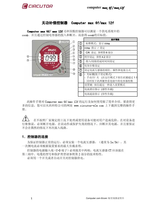
无功补偿控制器 Computer max 6f/max 12fComputer max 6f/ max 12f 功率因数控制器可以测量一个供电系统中的cos ϕ,并且通过控制电容器的投入和断开,而获得cos ϕ的目标值。
此操作手册对Computer max 6f/max 12f 的运行及如何使用做了简单介绍。
要获得更多的信息,您可以从西科特公司的网址 上下载到完整的操作手册。
在不按照厂家规定的工况下处理或使用设备可能对用户造成危险。
在对设备进行维修前,必须断开电源。
在误动作或保护失效的情况下,应断开其电源,并且要保证不会在偶然的情况下再次接入线路。
1.控制器的连接为保证控制器正常的运行,必须安装一个电流互感器,(通常为In/5A),其一次侧电流必须根据装置要求的最大负载求得。
控制器的电源输入端(C-D 端子)必须接其中两相,电流互感器CT 应该接在第三相中。
电缆的型号和保护类型请参照第2部分的技术特性。
必须用一个开关或者自动开关对控制器供电。
显示/键盘c 标准模式:显示cos ϕd cos ϕ 指示 / 设定e C/K 设定. 参照第6部分f 程序设定. 参照4.2部分g 投入/切除的延时时间设定h 电容步数设定i 设定电流互感器的相位、极性和连接方式 j- 光标键(处于设定模式)- 手动开/ 关 (在运行模式下按住此键超过1秒- 同时按下此两键查看连接中的电容器组数 设置键: 按住超过一秒进入设置模式 电流滞后指示 (感性负载) 电流超前指示 (容性负载)电流互感器CT接法必须正确,以保证能测量到整个负载电流和电容器电流之和。
2.技术特性电源和电压测量输入端(C-D)480V,400V,230和110V(ac)(+15% -10%);45-65 Hz , 最好接入到 L2-L3上电缆的型号和保护横截面积为1,5mm2;0,5 to 2A 熔断器采用 gl 类型电流测量线路电流互感器 (CT) , In /5 , 最好接入的L1相上,电缆的横截面积最小为2,5mm2电流测量范围0,1 to 5 A (最大过载 +20%)测量的精确度电压和电流:1%; cosϕ:2% ± 1 位cosϕ的默认值 1功率消耗 4.3 VA (110V) ; 3.7 VA (230V); 2.4 VA (400V);4.3VA(480V) 显示1行 x 3 位 x 7段显示 + 20个图标输出方式静态MOS管输出,最大60V,0.2A报警输出如果不使用,最后输出自动设置成报警输出符合标准EN 61010, EN 61000-3-2, EN 61000-3-3, EN 50081-2, EN 50082-1, EN 50082-2, EN 61000-4-2, EN 61000-4-4, EN 61000-4-8, EN 61000-4-5, EN 61000-4-11 , UL 94安全等级 / 绝缘等级等级 III,等级 II,参考标准:EN 61010-1,运行环境温度范围: -20ºC ~ +60ºC; 相对湿度 95% (无凝露). 最大海拔: 2000m保护等级IP51 (面板安装)IP30 (控制器外壳) , 符合EN-60529标准控制系统FCP (使最少的开关动作)Total(按照所需步骤连接和断开)3.四象限运行Computer max 6f/max 12f 控制器在4象限下运行(输入或输出有功功率)。


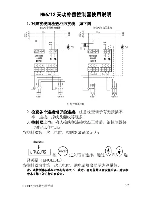
NR6/12无功补偿控制器使用说明1.对照接线图检查柜内接线:如下图2.检查各个连接端子的连接:注意检查端子有无接插不牢,虚接,掉线及漏线等现象!3.控制器上电:确认接线和连接状态正常后,给控制器接上额定工作电压;当控制器第一次上电时,控制器液晶显示为:按进入语言选择,通过和选择英语(ENGLISH).当控制器为非第一次上电时,通电后屏幕显示为测量值。
注:当控制器屏幕显示字母与本文不一致时,有可能是语言设置错误,建议参考本文第7条进行语言设定。
4.进入主菜单当控制器第一次上电并设置完语言选项后,直接进入主菜单此时屏幕显示为:当控制器为非第一次上电时,通电后屏幕显示为测量值,此时按下或 2秒后进入主菜单,此时屏幕显示为:5.手动设置A进入:通过和,当屏幕显示为,按进入,屏幕显示为,同时按下和 2秒,屏幕显示为:;B CT 变比设置:按下进入变比设置,通过和,设置CT变比,设置完毕后按;C 额定电压设置:设置完CT变比后,屏幕显示为:,按下进入额定电压设置,通过和,设置额定电压,设置完毕后按;D 接线方式设置:设置完额定电压后,屏幕显示为:,按下进入接线方式设置,先进行电压接线设置,显示选项分别为:U.L2-L3、U.L3-L1、U.L1-L2、U.L1-N、U.L2-N、U.L3-N, 通过和选择与实际电压接线一致的选项,按下;此时进入电流接线设置,显示选项为:I.1 DIR、I.1 REV、I.1 AUTO、I.2 DIR、I.2 REV、I.2 AUTO、I.3 DIR、I.3 REV、I.3AUTO, 通过和选择与实际电流接线一致的选项,按下;注:电流极性选择:DIR=直接连接,REV=反向连接,AUTO=自动极性选择(控制器定义);电流设置一般设置为AUTO。
E 目标功率因数设置:设置完接线方式后,屏幕显示为:,按下进入目标功率因数设置通过和,设定功率因数,设置完毕后按;F 手动响应值(C/K)设定:设置完目标功率因数后,屏幕显示为:,按下进入响应值(C/K)设置通过和设定响应值(C/K),按下;注:响应值(C/K)表:CK 值表-AC400V系统当响应值在表中查不到时请按响应值计算公式进行计算:G 投切延时设定:设定完响应值(C/K)数后,屏幕显示为:,按下进入投切延时设置通过和设定延时时间,按下;注:建议投切延时时间为60秒以上H 投切程序设定:设定完投切延时后,屏幕显示为:,按下进入投切程序选择,通过和设定选择响应的投切程序,按下;注:进入投切程序设定有以下投切程序供选择:NORMAL: 适用于电容器容量比为:1,2,4,4…前两步为调整步;CIRC.A:适用于电容器容量比为:1,1,1,1…投切逻辑为“先进先出”;CIRC.B:适用于电容器容量比为:1,2,2,2…第一步为调整步;STACK:适用于电容器容量比为:1,1,1,1…投切逻辑为“后进先出”;OPTIM:适用于以下多种电容量比:通过在最短时间内投入最少电容组步数来达到目标功率因数。

Power Factor ControllerMANUAL操作手冊手冊目錄章節1產品資訊 (10)1.1警告標示 (10)1.2 注意事項 (10)1.3 收貨與清點注意事項 (11)1.4 RAPIDUS 功率因數控制器 (11)1.5 RAPIDUS 前面板資訊 (13)章節2產品安裝 (15)2.1 安裝前準備 (15)2.2 盤面安裝 (15)2.3 產品接線圖 (18)2.4產品尺寸 (18)章節 3 選單目錄 (20)3.1 “第一次開機” 設定 (20)3.1.1 Dil / Lang. / 語言設定 (20)3.1.2日期 (21)3.1.3時間 (22)3.1.4 CT比值 (CTR) (22)3.1.5 PT比值 (VTR) (24)3.1.6 段數設定 (24)3.1.7重新啟動 (25)3.2 啟始畫面 (25)3.2.1設定目錄(Settings) (26)3.2.1.1 快速設定目錄(Quick setup Menu) (27)3.2.1.1.1 語言設定目錄(Language Setting) (27)3.2.1.1.2 日期目錄(Date Menu) (27)3.2.1.1.3 時間目錄(Time Menu) (27)3.2.1.1.4CT比值(CTR) (27)3.2.1.1.5PT比值(VTR) (27)3.2.1.1.6 電容器段數(Step number) (27)3.2.1.2 設定目錄(Setup Menu) (28)3.2.1.2.1 電力網路目錄(Network Menu) (29)3.2.1.2.1.1 CT比設定(CTR Setting) (29)3.2.1.2.1.2 PT比設定(VTR Setting) (30)3.2.1.2.1.3 需量時間設定(Demand period setting) (30)3.2.1.2.2 段數目錄(Step Menu) (31)3.2.1.2.2.1 輸入功率目錄(Ent. Power Menu) (31)3.2.1.2.2.2 輸入型式目錄(Ent. Type Menu) (31)3.2.1.2.2.3 預定目錄(Predefined Menu) (32)3.2.1.2.2.3.1 架構目錄(Structure Menu) (33)3.2.1.2.2.3.2 功率目錄(Power Menu) (33)3.2.1.2.2.3.3 數量目錄(Number Menu) (33)3.2.1.2.2.4 其他目錄(Other Menu) (34)3.2.1.2.3 補償目錄(Compensation Menu) (34)3.2.1.2.3.1 段數目錄(Steps Menu) (34)3.2.1.2.3.2 程式目錄(Program Menu) (35)3.2.1.2.3.2.1 Rapidus Program (36)3.2.1.2.3.2.2 Ascending Sequential program (36)3.2.1.2.3.2.3 Descending Sequential 模式 (38)3.2.1.2.3.2.4 Linear 模式 (40)3.2.1.2.3.2.5 Circular 模式 (42)3.2.1.2.3.2.6 手動模式(Manual program) (44)3.2.1.2.3.3 Target 1 Inductive 目錄 (44)3.2.1.2.3.4 Target 1 Capacitive 目錄 (44)3.2.1.2.3.5 Target 2 Inductive 目錄 (44)3.2.1.2.3.6 Target 2 Capacitive 目錄 (45)3.2.1.2.3.7 投入時間目錄(Activation Time Menu) (45)3.2.1.2.3.8 切離時間目錄(Deactivation Time Menu) (45)3.2.1.2.3.9 角度偏移目錄(Shift Angle Menu) (45)3.2.1.2.3.10 平均時間(Averaging Time) (46)3.2.1.2.3.11 固定段數目錄(Fixed Steps Menu) (46)3.2.1.2.4 學習目錄(Learn Menu) (46)3.2.1.2.4.1 系統接線學習目錄(Learn Conn. Menu) (46)3.2.1.2.4.1.1 啟動時學習(Learn at start) (47)3.2.1.2.4.1.2 段數(Step number) (48)3.2.1.2.4.1.3 重試計時器(Retry Timer) (48)3.2.1.2.4.1.4 重試次數(Retry Number) (49)3.2.1.2.4.2 輔助輸入目錄(Aux. Input Menu) (49)3.2.1.2.4.3 關閉模式(Off mode) (50)3.2.1.2.4.4 夜晚/白天模式(Night/Day Mode) (50)3.2.1.2.4.5 發電機模式(Generator Mode) (50)3.2.1.2.5 設備目錄(Device Menu) (50)3.2.1.2.5.1 語言設定(Language Setting) (51)3.2.1.2.5.2 銀幕對比設定(Contrast Setting) (51)3.2.1.2.5.3 密碼保護(Pass. Protection) (51)3.2.1.2.5.4 新密碼設定(New Password Setting) (52)3.2.1.2.5.5 背光啟動設定(Display On Setting) (52)3.2.1.2.5.6 背光顯示時間設定(Display On Time Setting) (52)3.2.1.2.6 用電量目錄(Energy Menu) (53)3.2.1.2.6.1 每日啟始時間設定(Start of day setting) (53)3.2.1.2.6.2 每月啟始日設定(Start of month setting) (53)3.2.1.2.6.3 kWh Setting (53)3.2.1.2.6.4 kWh E. Setting (53)3.2.1.2.6.5 kVArh I. Setting (54)3.2.1.2.6.6 kVArh C. Setting (54)3.2.1.2.7 通訊目錄(Communication Menu) (54)3.2.1.2.7.1 包率目錄(Baud Rate Menu) (54)3.2.1.2.7.2 設備ID目錄(Slave Id Menu) (54)3.2.1.2.8 警報目錄(Alarm Menu) (55)3.2.1.2.8.1 用電量警報目錄(Energy Alarm Menu) (55)3.2.1.2.8.2 相電壓警報目錄(V(L-N) Alarm Menu ) (56)3.2.1.2.8.3 線電壓警報目錄(V(L-L) Alarm Menu) (58)3.2.1.2.8.4 電流警報目錄(Current Alarm Menu) (58)3.2.1.2.8.5 實功率警報目錄(P Alarm Menu) (58)3.2.1.2.8.6 虛功率警報目錄(Q Alarm Menu) (58)3.2.1.2.8.7 視在功率警報目錄(S Alarm Menu ) (58)3.2.1.2.8.8 CosØ 警報目錄 (58)3.2.1.2.8.9 功因警報目錄(PF Alarm Menu) (58)3.2.1.2.8.10 段數警報目錄(Step Alarm Menu) (58)3.2.1.2.8.11 IN 警報目錄 (59)3.2.1.2.8.12 頻率警報目錄(F Alarm Menu) (59)3.2.1.2.8.13 電壓諧波警報目錄 (59)3.2.1.2.8.14 電流諧波警報目錄 (60)3.2.1.2.8.15 溫度警報目錄 (60)3.2.1.2.9 清除目錄(Clear Menu) (61)3.2.1.3 日期/時間目錄(Date/Time Menu) (63)3.2.1.4 系統資訊目錄(System Info Menu) (63)3.2.1.5 密碼目錄(Password Menu) (64)3.2.1.6 重新啟動目錄(Restart Menu) (64)3.2.1.7 出廠設定(Default Settings) (65)3.2.2 量測目錄(Measure Menu) (65)3.2.2.1 即時目錄(Instantaneous Menu) (66)3.2.2.2 電量目錄(Energy Menu) (66)3.2.2.2.1 Imp. Active Menu (輸入實功率目錄) (67)3.2.2.2.2 Exp. Active Menu (輸出實功率目錄) (69)3.2.2.2.3 Ind. Reactive Menu (電感性虛功率目錄) (69)3.2.2.2.4 Cap. Reactive Menu (電容性虛功率目錄) (69)3.2.2.3 需量目錄(Demand Menu) (69)3.2.2.3.1 電流目錄(Current Menu) (70)3.2.2.3.1.1 實功率目錄(Act. Power Menu) (71)3.2.2.3.1.2 虛功率目錄(Rea. Power Menu) (71)3.2.2.3.1.3 視在功率目錄(App. Power Menu) (71)3.2.2.4 相位圖目錄(Phasor diagram Menu) (71)3.2.2.5 諧波目錄(Harmonics Menu) (72)3.2.2.5.1 表格目錄(Table Menu) (72)3.2.2.5.2 圖形目錄(Graphic Menu) (73)3.2.3 補償目錄Comp. (Compensation) Menu (73)3.2.3.1 開關次數目錄(Switch Count Menu) (74)3.2.3.2 使用時間目錄(Conn. Time Menu) (74)3.2.3.3 DCM (動態電容器監測) (74)3.2.3.4 學習接線目錄(Learn Conn. Menu) (75)3.2.3.5 以學習接線目錄(Learned Conn. Menu ) (75)3.2.3.6 學習數目錄(Learn Steps Menu) (76)3.2.4 警報目錄(Alarms Menu) (76)3.2.4.1 相位1目錄(Phase1 Menu) (77)3.2.4.2 相位2目錄(Phase2 Menu) (78)3.2.4.3 相位3目錄(Phase3 Menu) (78)3.2.4.4 段數目錄(Step Menu) (78)3.2.4.5 其他目錄(Other Menu) (78)3.2.5 分析目錄(Analysis Menu) (79)3.2.5.1 最小值目錄(Minimum Menu) (80)3.2.5.1.1 每小時目錄(Hourly Menu) (80)3.2.5.1.1.1 相位1目錄(Phase1 Menu) (80)3.2.5.1.1.2 相位2目錄(Phase2 Menu ) (80)3.2.5.1.1.3 相位3目錄(Phase3 Menu) (80)3.2.5.1.1.4 其他(Ot her) (81)3.2.5.1.2 每日目錄(Daily Menu) (81)3.2.5.1.3 每月目錄(Monthly Menu) (81)3.2.5.2 最大值目錄(Maximum Menu ) (81)3.2.5.3 平均值目錄(Average Menu) (81)3.2.5.4 電量目錄(Energy Menu) (81)3.2.5.4.1 每小時目錄(Hourly Menu) (82)3.2.5.4.2 每日目錄(Daily Menu ) (82)3.2.5.4.3 每月目錄(Monthly Menu) (82)章節 4 出廠預設值 (84)章節 5 技術規格 (90)FIGURESFig. 1-1 RAPIDUS Display (13)Fig. 2-1 Placing RAPIDUS on the Panel (15)Fig. 2-2 Securing RAPIDUS (16)Fig. 2-3 Loosening of the Terminal Screws (16)Fig. 2-4 Inserting Cable into the Terminal Block (17)Fig. 2-5 Fixing the Cable to the Terminal Block (17)Fig. 2-6 RAPIDUS Connection Diagram (18)Fig. 2-7 Dimensions (18)Fig. 3-1 First Operation Settings (20)Fig. 3-2 Dil / Lang./ Язык Setting (20)Fig. 3-3 Date Setting (21)Fig. 3-4 Date Setting Example (21)Fig. 3-5 Current Transformer Ratio (22)Fig. 3-6 Entering a Value in Virtual Keyboard (23)Fig. 3-7 Voltage Transformer Ratio (24)Fig. 3-8 Step Structure (24)Fig. 3-9 Restart (25)Fig. 3-10 Startup Screen when the Connections Are Being Learned (25)Fig. 3-11 Startup Screen after the Connections Are Learned (26)Fig. 3-12 Settings Menu (26)Fig. 3-13 Quick Setup Menu (27)Fig. 3-14 RAPIDUS Prompt for saving (28)Fig. 3-15 Network Menu (29)Fig. 3-16 Current Transformer Ratio Setting (29)Fig. 3-17 Voltage Transformer Ratio Setting (30)Fig. 3-18 Demand Period Setting (30)Fig. 3-19 Step Menu (31)Fig. 3-20 Ent. Power Menu (31)Fig. 3-21 Ent. Type Menu (32)Fig. 3-22 Predefined Menu (32)Fig. 3-23 Other Menu (34)Fig. 3-24 Compensation Menu (34)Fig. 3-25 Compensation Menu (35)Fig. 3-26 RAPIDUS Mode Compensation Steps (36)Fig. 3-27 RAPIDUS Asc. Sequential Mode (37)Fig. 3-28 RAPIDUS Des. Sequential Mode (39)Fig. 3-29 RAPIDUS Linear Mode (41)Fig. 3-30 RAPIDUS Circular Mode (43)Fig. 3-31 Manual Mode Menu (44)Fig. 3-32 Averaging Time Menu (46)Fig. 3-33 Fixed Steps Menu (46)Fig. 3-34 Connection Setup (47)Fig. 3-35 Learning Connections at the Startup (48)Fig. 3-36 Waiting Time After Unsuccessful Connection Learning (48)Fig. 3-37 Retry Timer (49)Fig. 3-38 Retry Number (49)Fig. 3-39 Aux. Input (49)Fig. 3-40 Device Menu (50)Fig. 3-41 Contrast Setting (51)Fig. 3-42 Pass. Protection (51)Fig. 3-43 New Password Entry (52)Fig. 3-44 Display On Time Setting (52)Fig. 3-45 Energy Menu (53)Fig. 3-46 Baud Rate Setting (54)Fig. 3-47 Slave Id Setting (54)Fig. 3-48 Alarm Menu (55)Fig. 3-49 Energy Menu (55)Fig. 3-50 V(L-N) Alarm Menu (56)Fig. 3-51 Alarm Relay Setting (56)Fig. 3-52 Alarm Time Setting (57)Fig. 3-53 Hysteresis Setting (57)Fig. 3-54 Alarm Example (57)Fig. 3-55 V Harmonics Alarm Menu (59)Fig. 3-56 THDV High Limit Setting (59)Fig. 3-57 V3-V21 Harmonics High Limit Setting (60)Fig. 3-58 No Alarm Time Condition (60)Fig. 3-59 Invalid Limit (61)Fig. 3-60 Clear Menu (61)Fig. 3-61 Before Clearing (62)Fig. 3-62 After Clearing (62)Fig. 3-63 Initial Value Entered After Clearing (62)Fig. 3-64 Date/Time Menu (63)Fig. 3-65 System Info (63)Fig. 3-66 Password (64)Fig. 3-67 RAPIDUS Restart (64)Fig. 3-68 Default Settings (65)Fig. 3-69 Measure Menu (65)Fig. 3-70 Instantaneous Menu (66)Fig. 3-71 Imp. Active Energy Page (67)Fig. 3-72 Hour Start Example (67)Fig. 3-73 Day Start Example (68)Fig. 3-74 Month Start Example (68)Fig. 3-75 Demand Menu (69)Fig. 3-76 Demand Example (70)Fig. 3-77 Current Menu (70)Fig. 3-78 Phasor Diagram Menu (72)Fig. 3-79 Harmonics Table Menu (72)Fig. 3-80 Graphic Menu (73)Fig. 3-81 Comp. Menu (73)Fig. 3-82 Switch Count (74)Fig. 3-83 Conn. Time (74)Fig. 3-84 Learn Conn. (75)Fig. 3-85 Learned Conn (75)Fig. 3-86 Learn Steps (76)Fig. 3-87 Alarms Menu (77)Fig. 3-88 Phase1 Menu (77)Fig. 3-89 Step Menu (78)Fig. 3-90 Other Menu (78)Fig. 3-91 Analysis Menu (79)Fig. 3-92 Minimum Menu (80)Fig. 3-93 Hourly Menu (80)Fig. 3-94 Energy Menu (81)Power FactorController章節 1產品資訊章節 1 產品資訊1.1 警告標示注意:當您看到此符號,表示這是重要的資訊,必須在操作前將這些資訊納入考量。
Instructional ManuelRev c1.1 12-23-2011forJLD-612/ TET-612 PID Temperature Controller1. Product HighlightThermocouple supported: T, R, J, B, S, K, E, Wre3-Wre25.Thermo Resistor supported: Pt100, Cu50.Five ways outputs:•Two Relay alarms output•Two Relay output(J1), one PID relay output (J2, N.O.)•Two Relay alarm output, and one PID SSR signal output (for an external SSR).•Two Relay alarm output, and one PID SSR feedback output (for s SSR).•Once Relay alarm output (J1), one Relay control (J2).Time proportional PID controlled output to either a Relay output or the SSR control output. Temperature can be set to display in either Fahrenheit or Celsius.Manual control is capable2. SpecificationsOperating supply voltage: AC85-265V or DC85-360V.Power consumption: =< 2 Watt.Sampling speed: 4/sec.SSR activated voltage: open circuit: 6V; short circuit: 40mA.Accuracy: 0.2% of full scale.LED Display: 0.28 inch; Red color.Out of range indication: “EEEE”.Ambient temperature requirement: 0~+50 Deg C.Humidity requirement: =< 85% RH.Relay Contact : AC220V / 3A.Controller dimension: 48x48x82(mm).Opening for installation: 45x45(mm).3. Panel Illustrations and DescriptionsFigure11 -- AL1, relay J1 indicator.2 -- AL2, relay J2 indicator.3 -- AT, blanking during auto tuning process.4 -- Out, output indicator.5 -- Setting / Confirm.6 -- Digit select / Auto tuning.7 -- Select next parameter / value increment.8 -- Selection previous parameter / value decrement.9 -- Target value.10-- Current value.4. Parameter Settingi Press (SET) to enter setting mode, enter ”0089”, then press (SET) again.ii Press (v) and/or (^) and then (SET) to select parameters.iii Press (SET) to confirm entry or to selectiv Press (^) to until “End” appear in red display to exit parameter setting loop.a) Initialization parameter setting loop.Table 1. Initialization Parameters:Symbol Description Range Default Comment Inty Temp. sensor See table 2 Pt10.0Outy Method of controlled output 0,1,2,3,4 2 Note1Hy Step-Type Feedback 0-9999 0.3PSb Temp sensor errorcorrection coefficient -1000~1000deg CRd Heating=0;Cooling= 1 0,1 0 CorF Celsius=0;Fahrenheit= 1 0,1 0 End ExitTable 2. Temperature Sensor Type: Symbol Description RangeCommentTT Thermocouple -200 ~ 4000 Internal Resistant 100k RR Thermocouple -50 ~ 1600 Internal Resistant 100k JJ Thermocouple -200 ~ 1200 Internal Resistant 100k WRe WRe Thermocouple0 ~ 2300 Internal Resistant 100k BB Thermocouple 350 ~ 1800 Internal Resistant 100k SS Thermocouple -50 ~ 1600 Internal Resistant 100k KK Thermocouple -200 ~ 1300 C -328 ~ 2372 FInternal Resistant 100k EE Thermocouple -200 ~ 900 Internal Resistant 100k P10.0P10.0 Thermo Resistor -200.0 ~ 600.0 Constant Output 0.2mA P100 Pt100 Thermo Resistor -200 ~ 600 Constant Output 0.2mA Cu50Cu50 Thermo Resistor-50.0 ~ 150.0 Constant Output 0.2mANote: if a wrong probe is using, it may cause “EEE.E” error. Default is “K”Probe Connection:For J, K or any two wires probe, connection terminals are #9, #10For Pt-100 probe (3 wires), the red wire is connected to #8, and the two blues are connected to #9, #10Output setting ‘OutY’Fig. 20: Relay J1 and J2 as Alarm outputs; SSR and SV Disabled, it is normally used for upper/lower limits alarm trigger control. See Fig 21: Relay J1 alarm output; Relay J2 PID output controlled by SV. AH2, AL2 values are not used; SSR control output disabled. See Fig 22: Relay J1 and J2 as alarm outputs; SSR PID output 8V SSR signal. Target: SV 3. J1, J2 alarm output; differential control by SSR. See Fig 34. J1 alarm, differential control on J2, SSR disabled, AH2, AL2 disabled. See Fig 3<-Pt100Fig. 3(cooling)= 1(heating) Rd=0RdTo initial:HY) PV≥(SV + HY)–PV ≤(SVRelay latched or SSR On Relay latched or SSR OnTo stop:PV ≥ SV PV ≤ SVRelay unlatched or SSR off Relay unlatched or SSR off Note: HY = AH - AL4.Figureb) To enter PID parameter setting mode press (SET), then enter code “0036”, press (SET) again. Table 3. PID and Relevant Parameters:Symbol Description Range Default Comment P Proportional Band 0.1 ~ 99.9 (%) 5.0 Note 4I Integration Time 2 ~ 1999 (Sec) 100 Note 5D Differentiation Time 0 ~ 399 (Sec) 20 Note 6SouF Overshoot Suppression0.0 ~ 1.0 0.2 Note 7CoefficientOt Control Period 2 ~ 199 (Sec) 2 Note 8Filt Digital Filtering Strength 0 ~ 3 0 Note 9End ExitP,I and d parameters control the accuracy and respond time of the temperature controller. Auto-tuning is recommended for user who does not familiar PID control theory. P, I and d values should only be adjusted by professionals.Note 4Proportional Band (P): When P increases, fluctuation of object being controlled decreases. When P decreases, fluctuation of object being controlled increases. When P value is too small, system may become non-converge.Note 5Integration time (I): its purpose is to reduce static error. When I decrease, respond speed is faster but system is less stable. When I increase, respond speed is slower, but system is more stable.Note 6Differentiation time (d): its purpose is to control in advance and compensate delay. Setting d-value too small or too large would decrease system stability, oscillation or even non-converge.Note 7Overshoot suppression coefficient. When overshoot exists, increase SouF. When undershoot exists, decrease SouF.Note 8Control Period (ot): When ot gets smaller, heating/cooling cycle is drived faster, system respond speed is faster. But when using contact control (Relays), contacts wear out faster.When contact control (Relay) is used, normally set ot=5~15.When non-contact control (SSR) is used, normally set ot=2.Note 9Digital Filtering (Filt): Filt =0, filter disabled; Filt =1, weak filtering effect; Filt =3, strongest filtering effect; Stronger the filtering, more stable the readout, but has more readout display delay.C) To enter temperature and alarm parameter setting mode press (SET), then enter code “0001”, press (SET) again.Table 4. Temperature Setting and Alarm Related Parameters: Symbol Description Range Default CommentSVTarget Temperature (SV) With testing range 80.0 AH1Relay Closed With testing range80.0 AL1Relay Opened With testing range90.0 AH2Relay Closed With testing range80.0 AL2Relay Opened With testing range90.0 EndExit5. Auto-TuningBy simply press a single button the built-in artificial intelligent is activated to automatically calculate and set parameters (P, I, D, SouF, ot ) that fit the condition to be controlled.O N O FF O N O FFM easur i ng Cur veSVFigure 6.a) How to Start and stop auto-tuning process:i. To activate auto-tuning, press and hold (>) until “AT” indicator blinks, which indicates auto-tuning is in progress. When auto-tuning finish, “AT” indicator is off. Now newly calculated PID parameters are remembered and start to be used.a) ii. To EXIT during auto-tuning process, press and hold (>) until “AT” indicator turns off. Then previous PID parameters values are resumed. . Note, in order to have auto-tuning to work properly, a closed-loop system must be established; that is a SSR, heater, thermocouple are all connected. It may take an hour or up to 24hrs to complete the Auto-tuning. The amount of time it take is totally depends on how complicated the environment that the controller being installed.6. Connection Terminals (back view).Polarity of power at terminal 1 and 2 do not matter. The “R” is not an external resistor; it is only available from the Pt-100 thermistor.Relay J1: #3, #4 = normally closed, #4, #5 = normally open Relay J2: #13, #14 = normally openFig 7SSR ControlCaution: a heat-sink is required for the SSRRelay J1 ControlNote: terminal #11 is an opened slot and there is a diode installed for ambient temperature referencing. It’s not a missing screw or defective. For DC type controller, the power is 12V ~ 32V. The ‘R’ is not a resistor but it is a feedback resistance from the PT-100 probe. Do not reverse + / - when installing a thermocouple. If so, the increment and decrement reading will be opposite. For PT100 probe, red wire goes to #8 while two blues wires go to #9,#10Pt100 - Red lead terminal 8 Blue leads to terminals 9 and 10RelayNote: Vref can be AC or DC. It depends on the type of the relay it power7. Device Application Examplea) User wants to control temperature (T) of a furnace, and 0 ~ 1000 deg Celsius sensor range is required. Furnace is wanted to be maintained at 800 deg C. Alarm1 will go off if T>850 deg C, and Alarm2 will go off if T<750 deg C. System power supply is AC110V. Installation opening is 45x45(mm). SSR will be used to control the heating element.b) Choose JLD612 with a K-type thermocouple.c) See figure for connection diagram.d) Parameter setting:(Inty)=K; (SV)=800 deg C;(outy)=2; (AH1)=850 deg C;(Hy)=0.3; (AL1)=848 deg C;(psd)=0; (AH2)=750 deg C;=0; (AL2)=752 deg C;(rd)(CorF)=0;(auto-tuning is used to set PID parameters)e) Power up the controller. Keep pressing (>) to activate auto-tuning. When “AT” stop blinking, new PID parameters are generated and recorded for the system. The controller back to normal operation mode and the furnace temperature will stay at 800 deg ‘C.Presents by . All Rights Reserved.。