氮气保护 Nitrogen Inerting Design validation and testing Good Practice
- 格式:doc
- 大小:93.00 KB
- 文档页数:8

离心机氮气保护压力英文回答:Centrifuges are widely used in various industries for separating substances based on their density. In many cases, it is necessary to create a controlled environment inside the centrifuge to ensure the integrity and quality of the sample being processed. One common method to achieve thisis by using nitrogen gas as a protective atmosphere.The nitrogen gas is introduced into the centrifuge chamber to create a positive pressure, which helps prevent the entry of contaminants or oxygen that could potentially react with the sample. This is especially important when dealing with sensitive materials that are prone tooxidation or degradation.Maintaining the proper nitrogen pressure inside the centrifuge is crucial for the success of the process. The pressure requirements may vary depending on the specificapplication and the type of centrifuge being used. Generally, the nitrogen pressure should be set at a level that provides adequate protection while minimizing any potential damage to the sample.For example, in a laboratory setting where biological samples are being processed, a nitrogen pressure of around 2-5 psi (pounds per square inch) may be sufficient. This ensures a positive pressure environment without exerting excessive force on the samples.In an industrial setting, such as a pharmaceutical manufacturing facility, the pressure requirements may be higher. This is because the centrifuge is often used for large-scale production, and the samples being processed may be more sensitive to oxygen exposure. In such cases, nitrogen pressures of 10-20 psi may be necessary to maintain a suitable protective atmosphere.It is important to note that the nitrogen pressure should be carefully controlled and monitored throughout the centrifuge operation. This can be achieved using pressureregulators and gauges, which allow for precise adjustment and measurement of the nitrogen pressure.In addition to maintaining the proper nitrogen pressure, it is also essential to regularly check for any leaks or breaches in the centrifuge system. Even a small leak can compromise the integrity of the protective atmosphere and lead to contamination or sample damage.Overall, the nitrogen gas pressure in a centrifugeplays a vital role in ensuring the quality and integrity of the processed samples. By creating a protective atmosphere, it helps prevent oxidation, degradation, and contamination. Proper control and monitoring of the nitrogen pressure are necessary to optimize the centrifuge operation and achieve reliable results.中文回答:离心机在各个行业广泛应用于根据物质密度进行分离。

工业化工充氮保护用制氮机引言:保护气体在现代产业生产中应用广泛,其中充氮保护可以有效保护产品的质量,提高工业生产的稳定性和效率。
而制氮机作为充氮保护的设备,可以提供高纯度、高品质、稳定可靠的氮气,已经成为现代工业生产的不可或缺的设备之一。
一、充氮保护的概念及作用充氮保护是制造业生产过程中常用的一种保护方法,是在加工过程中充氮或以氮气覆盖物料表面,以防止氧气侵蚀和氧化反应。
充氮保护有助于抑制金属表面的氧化和脆化,并保持原有材料的性能。
在工业领域中应用很广,如船舶、石油、化工、医药、半导体、食品、化妆品等各个领域都需要使用充氮保护的方法。
二、制氮机的概念和工作原理制氮机(Nitrogen Generator)在工业生产中的作用非常重要。
它可以通过压缩空气生成纯化后的氮气,是一种高纯度、高品质、稳定可靠的氮气供应方式,可以满足各种工业应用领域的需求。
制氮机的工作原理是将压缩空气通过特殊的膜、吸附剂或分子筛等介质材料,分离出氧气和氮气。
由于两种气体分子大小不同,亲和力也不同,因此可以通过不同的过滤方式将其分离出来。
三、工业化工充氮保护用制氮机的优势1.高效性与传统的氮气瓶相比,制氮机可以持续、稳定地供应纯净、高质量的氮气,而且配套运行成本低。
2.方便性制氮机可以直接安装在工厂内部,不需要进行频繁的气体转运和维护,也不需要专业的工作人员进行维护和操作。
3.选择性强根据不同的工业需求,可以选择不同质量等级的氮气,比如高纯度氮气、超高纯度氮气等。
4.应用广泛不仅在充氮保护领域有广泛的应用,还可以在气体分析、实验室、设备处理等领域中使用。
四、结语总之,制氮机在工业化工充氮保护中的应用越来越广泛,可以满足各种工业应用领域的需求。
尤其在一些特殊行业,如印刷、塑料等,对纯度和稳定性的需求更高,制氮机的应用则更加必要。
所以,制氮机作为一种高效、方便、选择性强、应用广泛的氮气供应方式,将会在工业生产中持续发挥极其重要的作用。
氮气保护安全技术标准一、【背景介绍】1、易燃易爆物料与空气形成爆炸性气体,为了降低爆炸风险,在生产过程中通入惰性气体,控制氧气含量在爆炸极限以下,使混合气体(气相)惰性化,达到防爆目的。
2、易燃易爆物料包括:易燃液体(有机溶剂)形成的蒸发、可燃气体、可燃粉尘。
3、惰性气体:一般情况下使用氮气作为惰性气体。
二、【技术要求】1、易燃易爆物料只要氧气含量在某个值以下(极限氧含量LOC),就不会发生爆炸,不同的物质有不同的极限氧含量LOC值。
常用易燃易爆物料极限氧含量LOC值序号品名不发生爆炸时的极限氧含量(%)LOC氢气 4.5甲醇8.0乙醇8.5丙酮11.0苯9.0甲烷9.52、氢气的极限氧含量(%)4.5为所有物料中最低的,考虑安全系数,设定氮气置换后极限氧含量LOC 3%是安全可靠的。
2、公司所有溶剂储罐、反应釜、接受罐、离心机等使用易燃易爆有机溶剂、易燃易爆可燃气体、易燃易爆粉尘的设备(评估),都需要氮气保护。
4、氮气的纯度(N2)≥99%(工艺特殊要求除外),氮气总管压力≥0.3Mpa。
三、【实施指南】1、氮气保护控制方式a)手动进氮气方式:利用氮气压力表和阀门进行手动控制。
b)自动进氮气方式:利用氮封阀装置(压力差)进行自动控制。
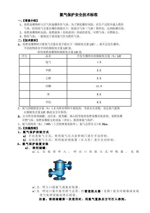
2、氮气保护装置安装a).溶剂储罐:a).1.安装带呼入、呼出口的阻火式呼吸器。
见图a).2.呼入口接氮气或氮封装置。
a).3.呼出口集中接至排气总管,经管道阻火器(见图)接至冷凝器或末端尾气处理设施处理后排放。
注意:溶剂储罐第一次使用时,用氮气置换后方可打入溶剂。
a).4.溶剂贮罐安装示意图b).溶剂接受罐:b).1.安装氮气管道、阀门及压力表,负压接受罐破真空时吸入氮气,至压力表为零或微正压。
b).2.常压接受罐安装氮气管道、阀门及压力表,进行手动氮气置换。
b).3.排气口集中接至排气总管,经管道阻火器接至冷凝器或末端尾气处理设施经处理后排放。
c).常压带溶剂反应罐(浸泡罐等):c).1.安装氮气管道时,注意将氮气管道深入离罐底200mm左右为宜,上部开小孔(俗称泪眼,防止料液被倒压出来)。
我是新手,这次的实验有可能要氮气保护,我以前没做过这个,心里没底,听说这个挺危险,想求有经验的大人给我些建议,谢谢!相关回复:作者: amshengtang 发布日期: 2006-03-08氮气是惰性气体,很安全的!作者: 水妖发布日期: 2006-03-08我不是说它本身危险,而是那个钢瓶,常听说弄不好就爆炸了,有点发憷!!作者: hoppy 发布日期: 2006-03-08氮气瓶一般接有高压阀和减压阀,高压阀显示瓶内气体的压力。
使用时先把减压阀关闭打开高压阀,再慢慢开启减压阀。
一般情况下这两个人阀门的旋转方向相反。
作者: 向前走发布日期: 2006-03-08不危险,很好操作的,我们经常用到,几乎就不用减压阀了作者: hysyjd 发布日期: 2006-03-08没啥子问题的,不过减压筏还是要用的。
一定要检查减压筏是否关闭,然后才开总筏,然后通过减压筏调节钢瓶本身是要进行年检的,所以一般不会发生爆炸,但是千万不要对钢瓶进行加热或者碰撞一类的。
作者: nktong 发布日期: 2006-03-08钢瓶爆炸的机会太小了,以至于可以忽略。
问题关键在于你是否会先对系统进行减压,然后再往里通氮气,如果那样的话,要小心。
减压时肯定是封闭系统,通氮气如果太快而你没来的急在合适的时候打开系统的话,系统里氮气压力太大,会爆的。
尤其是玻璃瓶子。
作者: 水妖发布日期: 2006-03-09困惑中……我的反应产物中有烯醇结构,所以想用氮气保护,但烯醇在进入下步反应前还要萃取,蒸馏,那时还要保护吗(杂保护?),烯醇常温下在空气中稳定吗(自言自语)作者: 水妖发布日期: 2006-03-09嘿嘿,悄悄问个小白问题,氮气保护不是要在密闭系统中吗?但反应中的回流,蒸馏装置都必须保证是敞开系统啊!杂办?(脸红……我很笨!)作者: weixiaobao-000 发布日期: 2006-03-09hehe:)作者: liuwenzhi1982 发布日期: 2006-03-09回流不一定是敞开系统的,可以用液封,就是在回流冷凝管的上方用液封。

氮气管实现波峰焊的节能氮气微孔弥散保护DECN2-PIPE在波峰焊过程中使用氮气,以形成一个惰性保护层来尽量减少焊料氧化是一项广为人知的技术,该技术不仅节省焊料,降低维护要求,而且提高焊料的润湿性,并可确保焊点的质量。
这种氮气保护技术可应用于现有的波峰焊机,只需要在锡锅中安装一个内部装有氮气管的保护罩即可。
因为氮气层可以覆盖整个锡锅,从而降低焊料氧化比例。
众所周知,在波峰焊中使用氮气保护可以显著降低锡渣的产生量并提高焊锡的润湿性能。
对于无铅波峰焊来说,氮气焊接保护具有更大的好处。
但是,以前缺少一种成熟的波峰焊氮气保护技术,本文介绍了一种适用于波峰焊的新型氮气保护系统,它使这项技术更具有成本效益,使用更加简便。
表明,这种技术具有以下优势:a、低氮气消耗量;b、低改造成本;c、降低焊接缺陷率。
d、低氮气管堵塞概率;e、极少锡渣形成;f;节省助焊剂使用量;g、减少机器的清洁次数;具体来说,要取得技术突破,就需要解决以下几个问题:a、改造工作必须尽可能简单,以降低成本。
b、锡波表面上的氧气浓度必须低于可接受的水平,以达到低锡渣产生率和低焊接缺陷率目标;c、必须尽量减少氮气消耗量,以提高该技术的性价比;d、尽量防止焊料飞溅以及助焊剂蒸汽堵塞氮气管,以确保氮气管的导通和持久工作要求;在电子行业,随着无铅焊接逐步取代有铅焊接,氮气保护在波峰焊中的价值进一步提升,因此,在无铅波峰焊工艺中,由于锡渣而产生的成本浪费造成的经济损失要大得多。
此外,与传统有铅焊接相比,无铅焊接的焊料润湿性先天不足,而且无铅焊点在形成过程中更易氧化,本文介绍了新一代波峰焊氮气保护系统的最新研发成果,该系统解决了上述难题,实验室和生产试验数据表明,这项已取得实践应用的新技术具有出色的性能和诸多优势。
关键点:氮气管的获取用先进的氮气气体弥散曝气技术,通过专业的特殊纳米孔径氮气管作为用气末端,仅需较低氮气流量就可以使得氮气均匀扩散在波峰焊或者回流焊表面、电子元器件焊接位置,达到惰性保护的目的,大大优于仅仅采用不锈钢管钻孔吹气或常规出风口吹气的技术缺陷,例如:气体耗量大,惰性保护效果不太明显。

氮气安全技术说明书第1部分化学品及企业标识化学品中文名称:氮气化学品英文名称:Nitrogen产品代码:产品推荐用途:化肥、氨、硝酸等化合物的制造,惰性保护介质,速冻食品、低温粉碎等的制冷剂、冷却剂,电子工业、化学气向淀积,还用作标准气、平衡气。
产品限制用途:非说明书规定用途的其他任何用途第2部分危险性概述物理化学危险:无色无臭气体,比空气轻,不燃烧。
有窒息性,在密闭空间内可将人窒息死亡。
若遇高温,容器内压增大,有开裂和爆炸的危险。
健康危害:空气中氮气含量过高,使吸入气氧分压下降,引起缺氧窒息。
吸入氮气浓度不太高时,患者最初感胸闷、气短、疲软无力;继而有烦躁不安、极度兴奋、乱跑、叫喊、神情恍惚、步太不稳,称之为“氮酩酊”,可进入昏睡或昏迷状态。
吸入高浓度,患者可迅速出现昏迷、呼吸心跳停止而致死亡。
潜水员深潜时,可发生氮的麻醉作用;若从高压环境下过快转入常压环境,体内会形成氮气气泡,压迫神经、血管或造成微血管阻塞,发生“减压病”。
环境危害:该物质对环境无危害,但氮大量排放时会使密闭空间的氧含量降低,有缺氧窒息的危险。
GHS危险性类别:标签要素:象形图:警示词:危险信息:含压力下气体,如受热可爆炸; 防范说明:预防措施:1、远离热源和火源。
2、操作人员必须经过专门培训,严格遵守操作规程。
事故响应: 1、如发生泄露,建议应急处理人员戴自给式呼吸器。
切断气源,然后抽排或强力通风。
漏气容器不能再用,且要经过空气臵换以清除可能剩下的气体。
2、皮肤接触:脱去污染的衣着,用清水彻底冲洗皮肤。
3、眼睛接触:提起眼睑,用流动清水或生理盐水冲洗,就医。
安全储存:不燃性压缩气体,保持容器密闭。
远离火种热源。
储存区应备有应急处理设备。
废弃处臵:遵守国家和当地法律法规,自然通风处理。
第3部分成分/组成信息第4部分急救措施皮肤接触:皮肤接触液氮,易导致冻伤,如果发生冻伤:将患部浸泡于保持在38~扎。
如有不适感,就医。
眼睛接触:立即翻开上下眼睑,用流动清水或生理盐水冲洗,就医。
氮气保护管理制度一、前言氮气是一种无色、无味、无毒的气体,用途广泛,可以用于化学工业、医药工业、食品工业等领域。
然而,氮气对人体的危害性也不容忽视,因此在使用氮气的过程中,需要严格管理和保护。
本文将就氮气的保护管理制度进行详细探讨。
二、氮气的危害性氮气本身对人体无毒,但在空气中的浓度达到一定水平时会导致窒息。
当氮氮气的浓度达到21%时,会取代空气中的氧气,造成呼吸困难,导致窒息。
此外,由于氮气是无味无色的,难以察觉,如果在一个密封或半密封的环境中,氮气的浓度不断增加,人们可能会不知不觉地处于高浓度的氮气环境中,造成窒息。
另外,液态氮对人体组织有极强的冷冻作用,接触液态氮会导致组织的冻伤。
因此在使用氮气的过程中,需要严格遵守相关的安全管理规定,防止发生事故。
三、氮气保护管理制度的制定1. 安全生产责任企业的主要负责人应当对氮气保护管理工作负有全面的安全生产责任。
要求主要负责人对氮气保护管理工作负责,确保氮气使用的安全。
2. 责任部门为了保障氮气使用的安全,企业应当设立专门的氮气安全管理部门,负责氮气的储存、使用、运输等工作。
3. 安全管理规定企业应当建立健全的氮气使用规定,包括氮气的储存、使用、运输等方面的细则,明确责任人和相关工作流程。
4. 安全教育培训企业应当对相关人员进行氮气的安全使用和操作培训,确保相关人员具备安全操作技能和安全意识,提高员工对氮气安全的重视程度。
5. 危险源的辨识与评估企业应当对氮气使用中可能出现的危险源进行全面的辨识与评估,采取相应的防控措施,保障员工的安全和健康。
6. 设备设施的安全管理企业应当对涉及氮气使用的设备设施进行定期的维护和检查,确保设备设施的安全性。
7. 应急救援措施企业应当建立健全的氮气泄漏和事故应急救援措施,保障一旦发生氮气事故能够及时、有效地进行救援处理。
8. 事故记录和分析企业应当建立完善的氮气事故记录和分析机制,对氮气事故进行详细的记录和分析,并及时调整相应的安全管理措施。
氮气管实现波峰焊的节能氮气微孔弥散保护DECN2-PIPE在波峰焊过程中使用氮气,以形成一个惰性保护层来尽量减少焊料氧化是一项广为人知的技术,该技术不仅节省焊料,降低维护要求,而且提高焊料的润湿性,并可确保焊点的质量。
这种氮气保护技术可应用于现有的波峰焊机,只需要在锡锅中安装一个内部装有氮气管的保护罩即可。
因为氮气层可以覆盖整个锡锅,从而降低焊料氧化比例。
众所周知,在波峰焊中使用氮气保护可以显著降低锡渣的产生量并提高焊锡的润湿性能。
对于无铅波峰焊来说,氮气焊接保护具有更大的好处。
但是,以前缺少一种成熟的波峰焊氮气保护技术,本文介绍了一种适用于波峰焊的新型氮气保护系统,它使这项技术更具有成本效益,使用更加简便。
表明,这种技术具有以下优势:a、低氮气消耗量;b、低改造成本;c、降低焊接缺陷率。
d、低氮气管堵塞概率;e、极少锡渣形成;f;节省助焊剂使用量;g、减少机器的清洁次数;具体来说,要取得技术突破,就需要解决以下几个问题:a、改造工作必须尽可能简单,以降低成本。
b、锡波表面上的氧气浓度必须低于可接受的水平,以达到低锡渣产生率和低焊接缺陷率目标;c、必须尽量减少氮气消耗量,以提高该技术的性价比;d、尽量防止焊料飞溅以及助焊剂蒸汽堵塞氮气管,以确保氮气管的导通和持久工作要求;在电子行业,随着无铅焊接逐步取代有铅焊接,氮气保护在波峰焊中的价值进一步提升,因此,在无铅波峰焊工艺中,由于锡渣而产生的成本浪费造成的经济损失要大得多。
此外,与传统有铅焊接相比,无铅焊接的焊料润湿性先天不足,而且无铅焊点在形成过程中更易氧化,本文介绍了新一代波峰焊氮气保护系统的最新研发成果,该系统解决了上述难题,实验室和生产试验数据表明,这项已取得实践应用的新技术具有出色的性能和诸多优势。
关键点:氮气管的获取用先进的氮气气体弥散曝气技术,通过专业的特殊纳米孔径氮气管作为用气末端,仅需较低氮气流量就可以使得氮气均匀扩散在波峰焊或者回流焊表面、电子元器件焊接位置,达到惰性保护的目的,大大优于仅仅采用不锈钢管钻孔吹气或常规出风口吹气的技术缺陷,例如:气体耗量大,惰性保护效果不太明显。
医气紫铜管系统的充氮保护焊接流程英文回答:The process of nitrogen purging in the medical gas copper piping system involves several steps to ensure asafe and effective welding procedure. Here is a detailed description of the process:1. Preparation: Before starting the welding process, it is important to ensure that all necessary safetyprecautions are in place. This includes wearing appropriate personal protective equipment (PPE) such as gloves, goggles, and a welding helmet. The work area should also be well-ventilated to prevent the accumulation of harmful fumes.2. Leak testing: Before introducing nitrogen gas into the system, it is crucial to conduct a leak test toidentify any potential leaks. This can be done by pressurizing the system with an inert gas, such as nitrogen, and using a leak detection solution to check for anybubbles or signs of leakage. If any leaks are detected, they should be repaired before proceeding.3. Purging: Once the system has been deemed leak-free, the next step is to purge the system with nitrogen gas. This is done to remove any oxygen or other contaminantsthat may be present in the piping system. The nitrogen gas is introduced at one end of the system while the other end is left open to allow the oxygen and contaminants to be pushed out. This process continues until the gas coming out of the open end is free from oxygen.4. Welding: After the purging process is complete, the welding can begin. It is important to use a welding technique suitable for copper pipes, such as TIG (Tungsten Inert Gas) welding. This technique provides precise control over the heat input and ensures a clean and strong weld.5. Post-weld purging: Once the welding is finished, it is necessary to perform a post-weld purge to remove any oxides or impurities that may have formed during the welding process. This is done by continuing the flow ofnitrogen gas through the system for a certain period of time, typically around 30 minutes. This helps to preventthe formation of corrosion and ensures the integrity of the welded joints.中文回答:医气紫铜管系统的充氮保护焊接流程包括以下几个步骤,以确保焊接过程的安全和有效性:1. 准备工作,在开始焊接过程之前,需要确保所有必要的安全措施已经采取。
优势突出的氮保护系统时间:2013-12-24来源:印刷英才网作者:李丁次相比而言,氮保护系统在我国尚处于起步阶段,但是,氮保护系统的高效、低能耗、低排放、环保等技术优势顺应时代的发展趋势,符合印刷工艺发展的世界潮流,已经引起国内的热切关注。
目前,传统UV固化系统已普遍应用于胶印、柔印、网印等印刷工艺,与此同时,其使用局限性也逐渐为用户所了解。
近些年来,随着新技术、新材料和新工艺的日新月异,针对印刷工艺的新型固化系统向传统UV固化系统发起了挑战。
其中,氮气保护UV固化系统(UV Inert System)是较为成熟的一种技术,亦简称为“氮保护系统”。
具体来讲,氮保护系统是指在UV固化系统中建立相对密闭的空间,将惰性气体(主要为氮气,故命名为“氮保护”)填充其中,从而可以极大地降低空气中氧气和水蒸气对UV固化反应的影响,因为氧气和水蒸气会参与UV固化反应,会损耗UV能量,产生臭氧和影响光敏剂的化学反应等。
相对传统UV固化系统,氮保护系统的技术优势明显,主要体现了以下9个方面:(1)传统UV固化系统的固化效果受各种条件限制较大,而氮气保护系统控制简单,且固化充分、高效。
(2)同条件下,传统UV固化系统的电能消耗较大(一般需要3~4根灯管),而氮气保护系统节能可达60%以上(一般仅需1~2根灯管)。
(3)采用传统UV固化系统的印刷品有明显的UV气味,甚至会长时间残留,而采用氮气保护系统的印刷品气味极低,并会很快消失。
(4)传统UV固化系统有臭氧产生,且需抽风;而氮气保护系统无臭氧产生。
(5)采用传统UV固化系统的印刷品会随着老化而逐渐显现黄变,而氮气保护系统对此有几大改善。
(6)传统UV固化系统会产生大量的热量,同时需要严格控制温度,而氮气保护系统仅产生较少的热量,可以保护设备和降低风险。
(7)传统UV固化系统经常出现爆裂(爆线)等典型的UV问题,而氮气保护系统对此有极大改善。
(8)在VOC控制方面,传统UV固化系统需要对印刷材料进行特殊调整,对工艺进行特殊控制,增加了不确定性;而氮气保护系统产生的VOC总量更低,控制更加简单、高效。
PPG Manufacturing DivisionGOOD PRACTICE FOR THE DESIGN, VALIDATION, AND TESTINGOF NITROGEN INERTING SYSTEMSJanuary 9, 1998GOOD PRACTICE GUIDELINESGood Practice Guidelines are produced by PPG Manufacturing Division to give advice on what should be considered in the design and operation of various aspects of manufacturing installations. The guidelines are just that; they are not to be interpreted as the definitive standards. They are intended as an aid to, not a substitute for, well engineered design. All installations using these guidelines should still be subject to process hazard assessment and other safety evaluations prior to and during use.PURPOSE AND APPLICABILITYThe purpose of this best practice is to help assure the safe design, operation, and maintenance of nitrogen inerting systems.DESIGN GUIDELINES1.Nitrogen inerting systems warrant a high degree of consideration during design. The inertingsystem design must take into account all of the following:a)the pressure ratings of all equipment in the system.b)the flow characteristics of gases inside the equipment. Irregularly shaped vessels can bemore difficult to inert than uniformly shaped vessels. Vessels where, by necessity, thenitrogen inlet and the process vent outlet are in close proximity can be more difficult to inertthan those vessels where these two lines are more separated.c)the physical properties of the materials processed in the system. The Minimum Oxygen forCombustion (MOC) for the materials in a system may be used to determine set points forsatisfactory inert conditions.d)the operating sequence for the process system. Some systems may require multiple purgecycles and/or continuous purging in order to ensure that inert conditions are maintainedthroughout all stages of the process.2.The default design basis for nitrogen inerting systems should assure that the oxygenconcentration inside the system being inerted remains at or below 5%, with the followingthree exceptions:a)Exception 1:In the case of systems handling single, predictable solvents/dusts, thetarget oxygen concentration for inerting may be set at 4% below the minimum oxygenconcentration (MOC) for combustion for that specific solvent/dust. Note that for hybridmixtures (those containing both solvent vapor and combustible dust), the material with thelower MOC should be used as the basis for determining acceptable target oxygenconcentration.b)Exception 2:Systems with a continuous oxygen monitor may be designed to assure thatthe oxygen concentration in the vessel remains at or below 8%, or in the case of systemshandling single, predictable solvents/dusts, 2% below the minimum oxygen concentrationfor combustion for the solvent/dust. . Note that for hybrid mixtures (those containing bothsolvent vapor and combustible dust), the material with the lower MOC should be used asthe basis for determining acceptable target oxygen concentration.c)Exception 3: Systems that may contain hydrogen should be designed to assure that theoxygen concentration in the vessel remains at or below 2% oxygen concentration.3.Nitrogen inerting systems should be designed according to the following methods of purging.Note that the equations provided (with the exception of the equation for sweep-through purging)assume that the inert gas being used contains a negligible oxygen concentration; validation of actual process operations is still required.a)Pressure Purging - wherein a pressure vessel is pressurized to a set pressure (commonly 15psig or 2 bar) and relieved for a sequence of cycles as necessary to achieve the desiredoxygen concentration; it is generally accepted that a sequence of three pressure purge cyclesof 15 psig (or 2 bar) establishes an inert atmosphere inside a vessel. Consider holding thepressure in the vessel for a period of time (commonly 10 minutes) during each purge cycle,especially for large or irregularly shaped vessels.Equation For Pressure Purging:C x= C0(P L/P H)xwhere C x = oxygen conc. after purge cycle xC0 = initial oxygen concentration (usually 20.9%)x = number of purge cyclesP L = vessel pressure before/after pressurization (usually ambient = 14.7 psia or 1 bar)P H = vessel pressure (max.) during pressurization (usually 29.7 psia or 2 bar)b)Vacuum Purging - wherein a vessel (that is capable of withstanding vacuum conditions) isevacuated to a set level of vacuum (commonly 50 mm Hg) and then the vacuum is brokenwith nitrogen to achieve the desired oxygen concentration; it is generally accepted that asingle vacuum purge cycle down to 50 mm Hg establishes an inert atmosphere inside avessel. Note that a vessel or process system needs to be relatively leak-tight for this type of purging to be reliable; vacuum should be broken expeditiously in order to minimize the risk of air ingress.Equation For Vacuum Purging:C x = C0(P L/P H)xwhere C x = oxygen conc. after vacuum cycle xC0 = initial oxygen concentration (usually 20.9%)x = number of vacuum cyclesP H = vessel pressure before/after vacuum (usually ambient = 760 mm Hg)P L = vessel pressure (min.) during vacuum cycle (commonly 50 mm Hg) one vacuum purge cycle (to 50 mm Hg) lowers oxygenconcentration to 1.4%c)Sweep-Through Purging - wherein a vessel is inerted by using a specified nitrogen gasvolume which is passed through the vessel in order to achieve the desired oxygenconcentration; the required volume of nitrogen can vary significantly depending upon vessel geometry, nitrogen flow rate, etc.Equation For Sweep-Through Purging:Q v t = V ln [(C1-C0)/(C2-C0)]where Q v = volumetric flow rate of nitrogen (e.g., ft3/min or L/min.)t = total sweep time (e.g., min.)V = volume of vessel (e.g., ft3,, L, m3)C0 = oxygen conc. of nitrogen (usually assume 0%)C1 = initial oxygen conc. in vessel (usually 20.9%)C2 = final desired oxygen conc. in vessel (typically 5%)Example: Given a 1000 U.S. gallon vessel (V = 133.7 ft3 or 3,786 L), a nitrogen purge flow rate (Q v) of 10 ft3 per minute (or 283 L/min.), a desired oxygen concentration (C2) of 5%, an initial oxygen concentration (C1) of20.9%, and assuming that the oxygen concentration in the nitrogen (C0) is essentially 0% -- how many minutesof purging time are theoretically required?t = {V ln [(C1-C0)/(C2-C0)]} / Q v = {133.7 * ln (20.9 / 5.0)} / 10= 19.1 minutesd)Nitrogen Bleed Purging - a modified form of sweep-through purging that is used tomaintain an inert atmosphere in a vessel during potentially dynamic conditions (e.g., solidscharging, centrifuging) wherein a relatively low, continuous flow of nitrogen (typically 3-5SCFM (85-142 lpm) for open systems, or 5-10 SCFH (142-283 lph) for closed systems) isapplied to a vessel in order to overcome the effects of diffusion, air entrained in solids asthey are charged, air drawn in due to venting of the vessel, etc.; this method of purgingneeds to be carefully validated in order to establish the necessary flow rate for eachspecific set of process conditions – validation should establish the minimum flow ratenecessary to maintain inertion while also avoiding excess emissions from the processe)Siphon Purging - a method of purging wherein the vessel is first filled with water (or othercompatible liquid), then as the vessel is emptied nitrogen is used to fill the headspace; thismethod of purging may be used to maintain vessels within a process inerted throughout acampaign as they are filled and emptied (thereby avoiding the need for additional purgecycles which will help to reduce nitrogen usage and solvent emissions); note that a carefulreview of the reliability of this type of purging should be conducted4.The typical components of a nitrogen inerting system for a reactor are shown in Figures 1(Automated System) and 2 (Manual System) at the end of this document. Similar designs may be used on other types of vessels.5.The use of continuous oxygen monitoring should be considered for certain high riskoperations (e.g., centrifuging, open solids charging, inerted vent headers). The necessity for oxygen monitoring must be assessed on a case-by-case basis according to the characteristics of the system being inerted. Factors that should be considered in assessing whether continuous oxygen monitoring is necessary include:∙the likelihood for uncontrolled introduction of air (e.g., room ventilation systemcharacteristics, placement of registers, HVAC system pressure changes in modules, etc.) ∙inerting validation results∙the likelihood of potential ignition sources (e.g., moving metal parts, static charge generation, etc.)∙quantities and physical properties of materials (both solvent and solids)6.Nitrogen inerting systems should be designed to prevent the backflow of process materialsinto the nitrogen supply system, particularly in pressurized applications.In some systems(e.g., those containing materials corrosive gases, hydrogen, toxic volatiles, etc.) the use of doublecheck valves should be considered.7.The design of nitrogen inerting systems and the nitrogen supply system should ensure that thechance of contamination of the nitrogen supply is minimized. The presence of cross-ties toother utility systems in the nitrogen supply header is strictly forbidden. The nitrogen supply line to the vessel should ideally be dedicated for nitrogen use only and should not be used for othermaterials.8.Process hazards analyses (PHA’s) should be conducted as part of the design of all nitrogeninerting systems. Specific consideration should be given to the potential need for monitoring(and alarming) for loss of nitrogen supply and to the materials of construction of the inerting system as compared to the process chemicals.OPERATION AND MANAGEMENT PRACTICES1. Every nitrogen inerting system will have a specified owner who is responsible for safeoperation, maintenance and design change review. This ownership will normally reside with the production department , at least to the extent that the nitrogen inerting system is containedwithin the buildings or process areas controlled by a given department.2. Current documents (e.g., P&ID’s) must be kept showing the design basis, current operatingbasis and current configuration of nitrogen inerting systems.3. Physical changes to a nitrogen inerting system and any operational changes in the system orconnected equipment must be reviewed as per plant change control procedures. If necessary, PHA’s should be conducted prior to making such changes.4. Operators and supervisors must be educated about the need for proper operation of nitrogeninerting systems, methods to verify proper operation, the design basis for nitrogen inerting systems to be used, proper operating procedures, and what to do in the event of upsets, orhigh oxygen conditions.5. Operating procedures must incorporate requirements for proper operation of nitrogeninerting systems. The nitrogen inerting system should be considered (and operated as) as a unit operation that is integral to the process(es) that it serves.6. Maintenance of nitrogen inerting systems should be performed in accordance with t he plant’spreventive maintenance program. All of the individual elements in the suggested nitrogeninerting designs in Figures 1 and 2 should be considered for inclusion in the maintenance program.VALIDATION AND TESTING PRACTICES1. All nitrogen inerting systems should be validated. Periodic revalidation and calibration ofcontrol instruments should be conducted in accordance with the plant’s preventive maintenanceprogram.Validation means testing to demonstrate or verify that the nitrogen inerting system can achieve and maintain the desired oxygen concentration (see item #2 in Design Guidelines) inside the process system throughout all phases of the process operation when flammable materials are present. 2. Validation and testing of nitrogen inerting systems should be conducted with a measuringdevice that is specifically designed for this purpose.Portable oxygen measuring devices that are intrinsically safe (e.g., Neutronics Model 910-GP-PM-IS) are available and suitable for thispurpose. The use of portable units designed for confined space entry monitoring is stronglydiscouraged, unless the unit is certified by the manufacturer to be accurate in reading low oxygen concentrations.REFERENCES1.NFPA 69 - Standard On Explosion Prevention Systems, 1992.2.NFPA 654 - Standard For the Prevention of Fire and Dust Explosions in the Chemical, Dye,Pharmaceutical, and Plastics Industries, 1982.3.Inerting - Methods and Measures for the Avoidance of Ignitable Substance-Air Mixtures in ChemicalProduction Equipment and Plants, Expert Commission for Safety in the Swiss Chemical Industry, Booklet 3, 1994.。