UI2011智能电参数测量仪操作规范
- 格式:docx
- 大小:42.72 KB
- 文档页数:2
三相电参数测量仪安全操作及保养规程前言三相电参数测量仪是一种常见的电测量仪器,在电力、工业、建筑等领域有着广泛的应用。
因此,正确的使用和保养对保证工作质量、保障人身安全、提高仪器使用寿命有着重要的作用。
本文就三相电参数测量仪的安全操作和保养规程进行详细介绍。
安全操作规程1、正确接线在使用三相电参数测量仪时,需要将其正确接线。
通常情况下,使用电缆连接测量仪和电源、被测电路等。
接线时,需要先将被测电路或电源等的电缆插入测量仪相应的接口中,再将测量仪的电缆插入被测电路或电源等的接口中。
在接线的过程中,需要检查电缆的绝缘是否完好,避免接触不良或短路等情况的发生。
2、使用正确的测量方法三相电参数测量仪有多种测量方法,如两线制、三线制、四线制等。
在使用测量仪进行测量时,需要根据被测电路的类型和测量要求选择正确的测量方法。
如果选用了错误的测量方法,则可能会造成数据出错或仪器损坏的情况。
3、注意保持测量仪干净和干燥为了保证测量的准确度和仪器的安全性,需要时刻注意保持测量仪的干净和干燥。
在使用之前,需要检查测量仪表面是否有灰尘和水珠等污物,如果有,应及时清理。
使用完毕之后,要将测量仪存放在干燥的环境中,避免水分和潮气的侵蚀。
4、避免机械损伤和电击三相电参数测量仪通常由金属外壳、控制按钮、接口等组成,因此容易受到机械损伤和电击的威胁。
在使用过程中,应当避免对测量仪进行强力撞击和摔落,以免导致仪器受损或撞坏其他设备。
在接线时,应注意是否有电压潜在危险,并采取有效的安全措施,避免电击事故的发生。
保养规程1、定期校验检查为了保证三相电参数测量仪的测量精度和稳定性,需要定期进行校验检查。
校验检查的周期和方法一般由相关的标准和规定来规定,一般为每年一次。
当测量仪的测量数据存在明显误差或者使用时间较长后,也需要进行校验检查。
2、及时进行维修和更换当发现测量仪的表面发生了破损、控制按钮失灵或接口生锈等情况时,需要及时进行维修或更换,以保证仪器的正常运行。
导电测量仪操作说明书一、产品简介导电测量仪是一种用于测量材料导电性能的仪器。
它通过测量电阻值来判断材料的导电特性,广泛应用于电子元件、半导体材料、电池和导电膜等领域。
二、产品组成1. 主机:包含电路板和显示屏,用于控制测量仪的操作和显示测量结果。
2. 探头:用于接触被测物体,通过探头与主机之间的连接进行电信号传输。
3. 电源:提供测量仪所需的电力。
三、操作步骤1. 检查电源:确保电源连接正常,主机显示屏显示电量充足。
2. 准备被测物体:确保被测物体表面干净、平整,无杂质和涂层。
3. 连接探头:将探头与主机连接,确保连接牢固且金属接触良好。
4. 打开主机:按下主机上的电源按钮,主机开始工作并显示相关信息。
5. 设置测量参数:在主机显示屏上的菜单中选择所需的测量参数,包括测量模式、单位等。
6. 开始测量:将探头轻轻触碰被测物体,确保探头与物体表面良好接触,并等待主机显示结果。
7. 记录和保存结果:根据需要,可以记录测量结果或将其保存到主机的存储器中。
8. 关闭主机:测量完成后,按下电源按钮并保持几秒钟,主机将自动关闭。
四、注意事项1. 在操作过程中,严禁用力过大,以免损坏探头或被测物体。
2. 在测量前应确保被测物体的表面干净,以免影响测量结果。
3. 如发现主机出现异常情况或测量结果不准确,应停止使用并联系售后服务。
4. 请勿将测量仪置于高温、潮湿或有腐蚀性物质的环境中,以免损坏设备。
5. 请定期对导电测量仪进行维护和校准,确保其正常工作。
五、维护与保养1. 清洁:使用柔软的布或棉纱蘸取少量清水或清洁剂,轻轻擦拭主机和探头表面,切勿用力擦拭。
2. 防尘:使用后,请将导电测量仪放置在干燥通风的地方,避免灰尘和杂物进入设备内部。
3. 定期校准:根据使用频率和环境条件,定期进行校准以确保测量结果的准确性。
六、故障排除如导电测量仪出现以下情况,请尽快联系售后服务:1. 主机无法开机或无法显示信息。
2. 探头损坏或连接异常。
华知科三相智能电参数测量仪说明书电参数测试仪使用方法:先将仪表的电源线按标准接法接到电源上。
将负载用电源接到固定的端子上。
按下仪表电源开关,接通仪表电源。
接通负载电源,并使负载通电,此时仪表应显示被测负载的各被测参数值。
如测量参数超出量程,则在相应的超量程参数窗口显示“OVER”,此时应立即终止测量,并切断负载电源,以免损坏仪表。
电参数综合测量仪,主要用来测定相关仪器仪表的电力参数,如电压、电流、电功率等。
电参数综合测量仪主要有数字电力参数测量仪、单相电力参数测量仪以及三相电力参数测量仪等等。
其中数字电力参数测量仪采用表贴技术,体积更小、质量更稳定,有丰富的接口功能及测量功能,能满足实验室工频产品检测要求。
电测量仪器是将被测电量或电参数与电学标准进行比较或提供准确比例的测量仪器。
科学研究、量值传递和工业测试中所用大量较量仪器(比较测量仪器的简称)都属于电测量仪器。
其用途广泛,在计量测试领域占有重要地位。
电测量仪器主要利用比例技术实现测量。
对于直流电,是利用同一电流在两电阻上产生的电压所形成的电压比例,或利用同一电压下两电阻的电流比例,然后结合标准器实现测量未知量。
提供比例的装置犹如天平,标准器则相当于砝码。
根据这一类比制成的较量仪器有直流电桥、直流电位差计等。
对于交流电,测量原理与直流电基本相同,只是电阻由阻抗代替。
因此,一般情况下比例是复数;实数比例或虚数比例只是其特例。
此外,还可利用两个有磁耦合的线圈得到与匝数成正比的电压实数比例,或与匝数成反比的电流实数比例。
根据这些原理制成的较量仪器有经典交流电桥、感应耦合比例臂电桥、交流电位差计、感应分压器、电流比较仪、互感器等。
除了上述电测量仪器外,还有利用电子电路组成的等值电路元件以及利用数字技术制成的有源电桥和数字电桥等。
PM99系列智能电参数测量仪用户使用手册DIGITAL POWER METER USER’S MANUAL普美仪器版权所有,未经授权禁止复制!智能电参数测量仪使用说明书目录检索第一章................基本原理第二章................型号选择第三章..........主要技术参数及指标第四章.......仪表使用说明及操作方法第五章................操作前准备第六章................装箱清单前言感谢购买【普美/DCUU】智能电参数测试仪(数字功率计,DIGITAL POWER METER),本产品手册包含仪器功能、操作流程等,为确保正确使用本仪器,在操作仪器前请仔细阅读手册。
请妥善保存手册,以便遇到问题能够快速查阅。
注意:1、对本手册的内容如有不同理解,以本公司技术部门的解释为准;2、本手册所描述的内容可能并非包含仪器的所有内容,本公司有权对产品的性能、功能、外观、附件、包装等进行改进或改变,而不另行通知;3、本手册版权归中中山市中翔仪器有限公司所有,其他任何公司或个人不得抄袭本手册。
手册内容有可能改变,恕不另行通知。
安全规定在使用本仪器的所有过程中必须注意下列安全规定,如果不合理使用,仪器所提供的功能可能受损。
本仪器使用了下列标记:高电压警告符号,为了避免人身伤害或损坏仪器,操作者应参照说明书开关接通符号开关断开符号警告勿在爆炸性环境下操作。
不要在放有易燃易爆品的地方使用仪器。
在这种环境下使用任何电气仪器都有可能造成安全伤害。
保护地线打开电源线前确保接好了保护地线以防电机,本仪器接地端为电源插座的地线端。
供电电源打开电源前请确保供电电源电压与额定电压匹配。
勿取下仪器的任何外壳部分有些地方具有高电压,未经特别许可严禁取下仪器外壳和拆卸仪器的任何部件。
第一章基本原理一、原理框图图1原理框图仪器主要由输入(电压、电流输入)、微型计算机、显示和接口部分组成。

72-72182 234 6 7 8101111121314151719191920202021212122232323Title Page ContentsOverview Unpacking Inspection Safety Information Rules for Safe Operation International Electrical Symbols The Meter Structure Functional Buttons and auto power off Display Symbols Measurement Operation A. DC Voltage Measurement B. AC Voltage Measurement C. Measuring Resistance D. Testing Diodes E. Testing for Continuity F. AC Current Measurement Specifications A. General Specifications B. Environmental Restriction Accuracy Specifications A. AC Voltage B. DC Voltage C. Resistance D. Continuity Test E. Diode Test F. AC Current Maintenance A. General Service B. Replacing the BatteryOverviewThis Operating Manual covers information on safety and cautions. Please read the relevant information carefully and observe all the Warnings and Notes strictly. WarningTo avoid electric shock or personal injury, read the “Safety Information” and “Rules for Safe Operation” carefully before using the Meter.Digital Multimeter Model 72-7218 (hereafter referred to as “the Meter”) is 3 1/2 digits with steady operations, fashionable structure and highly reliable measuring instrument. The Meter uses large scale of integrated circuit with double integrated A/D converter as its core and has full range overload protection.The Metercan measure AC/DC Voltage, AC Current, Resistance, Diodes, and Continuity.Unpacking InspectionOpen the package case and take out the Meter. Check the following items carefully to see any missing or damaged part:Item Description Qty 1 English Operating Manual 1 piece 2 Test Lead 1 pair In the event you find any missing or damage, please contact your dealer immediately.Safety InformationThis Meter complies with the standards IEC61010: in pollution degree 2, overvoltage category (CATII 600V, CAT III 300V) and double insulation.CATII: Local level, appliance, PORTABLE EQUIPMENT etc., with smaller transient overvoltages than CATIII.CAT III: Distribution level, fixed installation, with smaller transient overvoltages than CAT IVUse the Meter only as specified in this operating manual, otherwise the protection provided by the Meter may be impaired.In this manual, a Warning identifies conditions and actions that pose hazards to the user, or may damage the Meter or the equipment under test.A Note identifies the information that user should pay attention to.International electrical symbols used on the Meter and in this Operating Manual are explained on page 6.Rules for Safe Operation WarningTo avoid possible electric shock or personal injury, and to avoid possible damageto the Meter or to the equipment under test, adhere to the following rules:● Before using the Meter inspect the case. Do not use the Meter if it is damaged or the case (or part of the case) is removed. Look for cracks or missing plastic. Pay attention to the insulation around the connectors.● Inspect the test leads for damaged insulation or exposed metal. Check the test leads for continuity. Replace damaged test leads with identical model number or electrical specifications before using the Meter.● Do not apply more than the rated voltage, as marked on the Meter, between the terminals or between any terminal and grounding. If the value to be measured is unknown, use the maximum measurement position and reduce the range step by step until a satisfactory reading is obtained.● When measurement has been completed, disconnect the connection between the test leads and the circuit under test, remove the testing leads away from the input terminals of the Meter and turn the Meter power off.● The rotary switch should be placed in the right position and no any changeover of range shall be made during measurement is conducted to prevent damage of the Meter.● Do not carry out the measurement when the Meter’s back case and battery compartmentare not closed to avoid electric shock.● Do not input higher than 600V between the Meter’s terminals and the grounding to avoid electric shock and damages to the Meter.● When the Meter working at an effective voltage over 60V in DC or 30V rms in AC, special care should be taken for there is danger of electric shock.● Use the proper terminals, function, and range for your measurements.● Do not use or store the Meter in an environment of high temperature, humidity, explosive, inflammable and strong magnetic field. The performance of the Meter may deteriorate after dampened.● When using the test leads, keep your fingers behind the finger guards.● Disconnect circuit power and discharge all high-voltage capacitors before testing resistance, continuity and diode.lead to electric shock and personal injury.● When servicing the Meter, use only the same model number or identical electrical specifications replacement parts.● The internal circuit of the Meter shall not be altered at will to avoid damage of the Meter and any accident.● Soft cloth and mild detergent should be used to clean the surface of the Meter when servicing. No abrasive and solvent should be used to prevent the surface of the Meter from corrosion, damage and accident.● The Meter is suitable for indoor use.● Turn the Meter off when it is not in use andtake out the battery when not using for a long time.● Constantly check the battery as it may leak when it has been using for some time, replace the battery as soon as leaking appears. A leaking battery will damage the Meter. International Electrical SymbolsContinuity TestThe Meter Structure (see figure 1)(figure 1)1. Input Terminals2. LCD Display3. Functional Buttons4. Rotary Switch5. Trigger: press the lever to open thetransformer jaws. When the pressure on the lever is released, the jaws will close.6. Hand Guards: to protect user’s hand from touching the dangerous area.7. Transformer Jaws: designed to pick up the AC current flowing through the conductor. It could transfer current to voltage. Thetested conductor must vertically go through the jaw center.Functional Buttons and auto power off1. HOLD Press HOLD to enter and exit hold mode. Press and hold HOLD button while turning on the Meter, auto power off be canceled.2. MAX Press MAX to start recording and updating of maximum values.3. SELECT Under Ω ranging, resistancemeasurement mode is default, press SELECT to select continuity measurement mode or diode measurement mode.4. Auto power off To preserve battery life, the Meter automatically goes into a “sleep” mode if you do not press any button for around 10 minutes. The Meter can be activated by pressing any effective button (refer to The Effectiveness ofFunctional Buttons), then returns to the display for the function selected previously.5. Buzzer The buzzer phonate go with every time button be effectual pressed. When the meter will auto power off in 1 minute the buzzer beeps five times. Before power off there will be a long time buzzer beeps.6. The Effectiveness of Functional Buttons Not every functional buttons can be used onevery rotary switch positions. Below table describe which functional buttons can be used on which rotary switch positionsΩ •Display Symbols (see figure 2)(figure 2)Measurement OperationA. DC Voltage Measurement (see figure 3)Warning To avoid harms to you or damages to the Meter from eletric shock, do not attempt to measure voltages higher than 600V AC/DC.To measure DC voltage, connect the Meter as follows:1. Insert the red test lead into the terminal and the black test lead into the COM terminal.2. Set the rotary switch to .3. Connect the test leads across with the object being measured.The measured value shows on the display.VΩ(figure 3)Note:When DC voltage measurement has been completed, disconnect the connection between the testing leads and the circuit under test and remove testing leads from the input terminals.B. AC Voltage Measurement (see figure 4)WarningTo avoid harms to you or damages to the Meter from eletric shock, do not attempt to measure voltages higher than 600V AC/DC.To measure AC voltage, connect the Meter as follows:1. Insert the red test lead into theVΩterminal and the black test lead into the COM terminal.2. Set the rotary switch to .3. Connect the test leads across with the object being measured.The measured value shows on the display.(figure 4)Note:When AC voltage measurement has been completed, disconnect the connection between the testing leads and the circuit under test and remove testing leads from the input terminals.C. Measuring Resistance (see figure 5) WarningTo avoid damages to the Meter orto the devices under test, disconnect circuit power and discharge all the high-voltage capacitors before measuring resistance.To measure resistance, connect the Meter as follows:1. Insert the red test lead into the terminal and the black test lead into the COM terminal.2. Set the rotary switch to ; resistance measurement (Ω) is default or pressSELECT button to select Ω measurement mode3. Connect the test leads across with the object being measured.The measured value shows on the display.Note: ● To remove the objects being tested from the circuit when measuring can obtain a more accurate result.● When resistance measurement has been completed, disconnect the connection between the testing leads and the circuit under test and remove testing leads from the input terminals.ΩVΩD. Testing Diodes (see figure 6) WarningTo avoid damages to the Meter or tothe devices under test, disconnect circuit power anddischarge all the high-voltage capacitors before testing diodes.To test the diode out of a circuit, connect the Meter as follows:1. Insert the red test lead into the terminal and the black test lead into the COM terminal.2. Set the rotary switch to and press SELECT button to select measurement mode.3. For forward voltage drop readings on any semiconductor component, place the red test lead on the component’s anode and place the black test lead on the component’s cathode.ΩVΩ(figure 5)Note:● To remove the objects being tested from the circuit when measuring can obtain a more accurate result.● When diode testing has been completed, disconnect the connection between the testing leads and the circuit under test and remove testing leads from the input terminals.E. Testing for Continuity (see figure 7)Warning To avoid damages to the Meter or to the devices under test, disconnect circuit power and discharge all the high-voltage capacitors before measuring continuity.To test for continuity, connect the Meter as follows:1. Insert the red test lead into theterminal and the black test lead into the COM terminal.VΩ(figure 6)Ω(figure 7)2. Set the rotary switch to and press SELECT button to select measurement mode.3. The buzzer sounds if the resistance of a circuit under test is less than 10Ω.4. The buzzer may or may not sounds if the resistance of a circuit under test is more than 10Ω.Note:When continuity testing has been completed, disconnect the connection between the testing leads and the circuit under test and removetesting leads from the input terminals.F. AC Current Measurement (see figure 8)WarningTo avoid electric shock, never measure current while the test leads are inserted into the input terminals and disconnect test leads and tested circuit connection.Never attempt an in-circuit current measuremnet where the open-circuit voltage between the circuit and the ground is greater than 600VUser proper function, and range for the measurement.To measure current, do the following:1. Set the rotary switch to 20A ,200 A or 600 A .2. Press the lever to open the transformer jaws.3. Center the conductor within the transformer jaw, then release the Meter slowly until the trasnformer jaw is completely closed, Make sure the conductor to be tested is placedat the center of the transformer jaw,otherwise it will casue deviation. The Meter can only measure one conductor at a time, to meausre more than one condutor at atime will cause deviation.Note:When current measurement has been completed,disconnect the connection between the conductor under test and the jaw, and remove the conductor away from the transformer jaw of the Meter.(figure 8)SpecificationsA. General Specifications● Display: 3 1/2 digits LCD display, Maximum display 1999● Auto Polarity Display● Overloading: Display OL●● Measuremnet Deviation: When theconductor being meaured is not placed in a correct position during AC currentmeasurement, it will cause ±3% readingdeviation.● Drop Test: 1 meter drop test passed● Max. Jaw Size: 28mm diameter● Projected Max. Current conductor size:26mm diameter.● Power: 9V battery● Sleep Mode (can be disabled)● Dimensions: 76mm x 208mm x 30mm.● Weight: Approximate 260g (battery included)B. Environmental Restrictions● The Meter is suitable for indoor use.● Altitude: Operating: 2000mStorage: 10000m● Safety/ Compliances: IEC 61010 CATII600V, CATIII 300V over voltage and double insulation standard.● Pollution degree: 2● Temperature and humidity:Operating: 0℃~30℃ (≤75%R.H);30℃~40℃ (≤70%R.H);40℃~50℃ (≤45%R.H);Storage: -20℃~+60℃ (≤75%R.H)Accurate SpecificationsAccuracy: ±(a% reading + b digits), guarantee for 1 year.Operating temperature: 23℃±5℃Relative humidity: ≤75%R.HTemperature coefficient: 0.1×(specified accuracy) /1℃A. AC Voltage: Auto rangingRange Resolution Accuracy2.000V 1mV20.00V 10mV ±(1.2%+5)200.0V 100mV600V 1V ±(1.5%+5) Remarks:● Overload protection:600V rms● Input impedance: 10MΩ // <100pF● Displays effective value of sine wave (mean value response).● Frequency response: 40Hz~1kHz.B. DC Voltage: Auto rangingRange Resolution Accuracy200.0mV 0.1mV ±(0.8%+3)2.000V 1mV20.00V 10mV ±(0.8%+1)200.0V 100mV600V 1V ±(1%+3) Remarks:● Input impedance: 10MΩ● Overload protectionl: 600V rmsC. Resistance: Auto rangingRange Resolution Accuracy 200.0Ω 100mΩ ±(1.2%+2) 2.000kΩ 1Ω20.00kΩ 10Ω±(1%+2) 200.0kΩ 100Ω2.000MΩ 1kΩ ±(1.2%+2) 20.00MΩ 10kΩ ±(1.5%+2)Remark:● Overload protection: 600VpD. Continuity TestRange Resolution AccuracyAround ≤10Ω,the buzzer beeps.Remark:● Overload Protection: 600Vp● Open circuit voltage approximate 0.45V.● The buzzer may or may not beeps when the resistance of a circuit under test is more than 10Ω.Remarks:● Overload Protection: 600Vp● Open circuit voltage approximate 1.48V.100mΩF. AC Current: Auto rangingRange Resolution Accuracy20.00A 0.01A ±(2.0%+5)200.0A 0.1A ±(1.5%+5)600A 1A ±(2.0%+8) Remarks:● Overload protection: 600A rms● Frequency Response: 50Hz~60Hz● Displays effective value of sine wave (mean value response).● To adjust reading in accordance witheffective value.MaintenanceThis section provides basic maintenance information including battery replacement instruction.WarningDo not attempt to repair or service your Meter unless you are qualified to do so and have the relevant calibration, performance test, and service information.To avoid electrical shock or damage to the Meter, do not get water inside the case.A. General Service● Periodically wipe the case with a damp cloth and mild detergent. Do not use abrasives or solvents.● To clean the terminals with cotton bar with detergent, as dirt or moisture in theterminals can affect readings.● Turn the Meter power off when it is not inuse.● Take out the battery when it is not using fora long time.● Do not use or store the Meter in a placeof humidity, high temperature, explosive,inflammable and strong magnetic field.B. Replacing the Battery (see figure 9)WarningTo avoid false readings, which could lead to possible electric shock or personal injury,replace as soon as the batteryMake sure the transformer jaw and the tets leads are disconected from the circuit being tested before opening the case bottom.To replace the battery:.1. Turn the Meter off and remove all theconnections from the input terminals.2. Turn the Meter’s case top down.3. Remove the screw from the batterycompartment, and separate the batterycompartment from the case bottom.4. Remove the old battery from the batterycompartment.5. Rejoin the case bottom and the batterycompartment, and reinstall the screw.(figure 9)The content is subject to change without prior notice© Copyright 2009 Tenma Test Equipment All rights reserved.Tenma Test Equipment405 South Pioneer Blvd. Springboro, Ohio 45066。
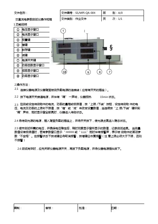
1.功能说明文件编号:SS/MPI-QA-004 版别:A/0 文件类别:作业文件页次:1/1
文件名称:
交直流电参数测试仪操作规程
①电压显示窗口
②电流显示窗口
③预置键
④增键
⑤锁存键
⑥减键
⑦电源开关键
⑧功率因数显示窗口
⑨频率显示窗口
⑩功率显示窗口
■ §10
2.操作方法:
连接仪器电源及仪器背面被测负载电源的连接线(应带有开关的插座)。
2.1
2.2 按下电源开关接通电源,并伴有“嘀” 一声响,仪器预热15min状态。
估测或设定待测物件的电流、功率的量程或极限值,按“上限/下线”按钮,设定待测物件的电压、电流及功率的上限和下限值,按“增”或“减”来改变设置数值,当连续按“上限/下线”键听到“嘀”声响,同时显示窗全部亮时,仪器进入待测状态。
2.3
2.4将待测光源的电源,插入背面负载的插座上,并将开关按下,使光源点亮进入稳态状态。
2.5调节测试所需的电压,并确保电压稳定后,稍时观察显示窗所显示的数值,记录测试结果。
当测量数值设有极限值时,若有参数窗口显示“ HHHH或“ LLLL”同时伴有报警声,表示被测物件的某项参数“不合格”。
在报警状态下按减键⑥将取消报警,按增键④恢复报警(注意上限必须大于下限,否则不报警)
警,
2.6测试完毕时,应先关断仪器电源开关,再拔下负载电源,并将仪器电源插头拔下。
编制:审核:批准:日期:。
转辙机综合测试仪使用说明书一、开机/关机1.开机按下键并保持2-3s后,仪器开机并开始初始化自检,自检期间蜂鸣器鸣响。
初始化完毕后进入主菜单,蜂鸣器停止鸣响,进入主菜单开机完毕。
主菜单显示当前存储器通道号、当前道岔号、当前日期、时钟及电池电量。
2.关机在任意状态下,按下键后仪器即时关机,关机后关闭所有电源。
并将部分设定内容存储。
二、设定内容及操作方法1.显示液晶对比度当显示液晶受温度、光照等因数造成显示不清时,你可以通过设置液晶的显示对比度进行修正。
在主菜单下按键及键可调整液晶的显示对比度。
设定内容可自动保存。
2.显示液晶辅助背光开关当使用环境的光线不足、能见度较低,你可以开关液晶的辅助背光。
在主菜单下按键及键可开关液晶的辅助背光。
设定不可保存。
3.修改当前通道在自动、手动、显示等菜单中按键及键可改变当前的默认存储通道。
4.设置菜单在主菜单下按键后进入设置菜单,你可以在此菜单中修改道岔号、当前时钟、打印数据间隔。
1)改变当前的道岔号在设置菜单中选择1进入。
显示当前的道岔号,随光标位置输入新的道岔号后按确定完成修改。
2)调整日期、时钟在设置菜单中选择2开始进行调整。
随光标位置输入新的日期、时间后按确定完成修改。
3)修改打印数据间隔在设置菜单中选择3进行修改。
首先显示的是当前的打印数键或键来进行修改,设定范围为0.15s – 0.9s,设定间隔为 0.15s。
三、电池充电当电池电量降至30 %时,仪器的蜂鸣器鸣响,电池欠电报警,请立即停止使用,并请及时充电。
当可能较长时间不用时,请带电保存。
并请每3个月充电一次。
电池的充电时间为12-16 小时。
四、连接、联线请将综合测试线的电压测试线并接在转辙机电机电源线的任意两相上。
请将综合测试线的电流测试线串接在转辙机电源线的回路中。
请将综合测试线的时间测试线接在转辙机到位闭合的一组备用接点上。
请将拉力传感器替换转辙机与安装装置的连接销后用联线与仪器连接。
请将压力传感器替换转辙机被测压力腔侧的二动调节阀后用联线与仪器连接(只限于电液转辙机)。
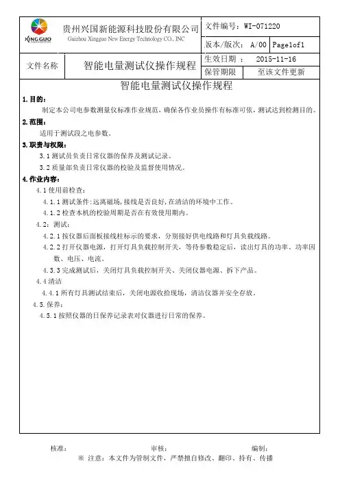
文件制修订记录1.0目的/Aim:1.1为电参数测量仪操作提供作业指导书,确保电参数测试仪对产品工作电压、电流、电能量、功率和功率因子的测量精度。
2.0参考文件/Reference Instruction:2.1电参数综合测量仪用户手册。
3.0设备/材料/ Equipment/Material:3.1 AN8720P电参数测试仪(需权威计量部门定期校验并在一定的期限范围内使用)。
4.0准备/要求/Prepare/Requirement:4.1 电源插座的下方放入保险丝,仪器接通电源, 确保输入电压为单相220伏,测试场所保持整齐、干净。
5.0安全/维护/Safety/Maintenance:5.1 使用本仪器之前,请认真阅读操作规程及使用说明书,并严格按规程操作,以免造成操作人员的人身伤害或仪器损坏。
5.2 测量过程中,请勿触摸测量仪后面板上的接线部分,谨防触电!5.3 拆接测量仪后面板上的接线时,请务必在切断电源后,再行操作!5.4 各输入输出端子连接部分应采取绝缘保护措施,以防止触电事故。
5.5 万一发生任何问题,请立即关闭电源。
5.6 不要让测量仪长时间超量程运行,测量仪允许的冲击信号幅值不要超过正常信号的1.6倍.测量仪不用时,请将仪表电源线拔下。
5.7 测量仪长期不用时,请包装保存在干燥、无粉尘、无强烈震动的环境下。
5.8 测量仪长时间保存后再次使用,使用前应开机30分钟后再测量使用。
6.0操作程序/Operation Process:6.1仪器参数设置6.1.1非锁定时,按“参数设置”按键即可进入参数设定状态.进入参数设定状态后,提示符“SET”点亮.每按一次“参数设置”按键会依次进入通讯地址、波特率、校验位、门限电流值显示单位的参数设定,相应提示符同时点亮.参数设定状态下,用“增/减”键可修改参数数值.第五次按下“参数设置”键,退出参数设定状态,提示符“SET”熄灭,设置值将被保存。
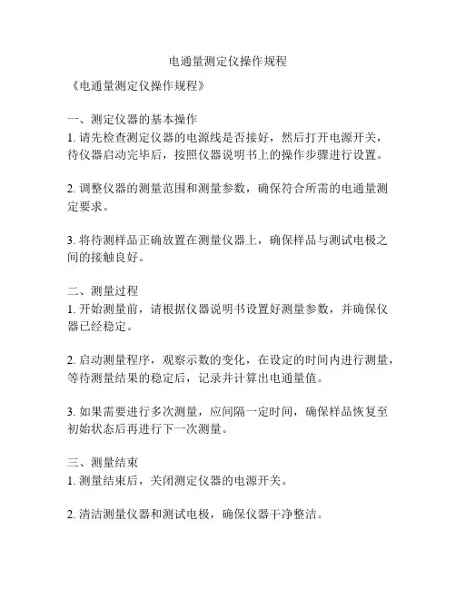
电通量测定仪操作规程
《电通量测定仪操作规程》
一、测定仪器的基本操作
1. 请先检查测定仪器的电源线是否接好,然后打开电源开关,待仪器启动完毕后,按照仪器说明书上的操作步骤进行设置。
2. 调整仪器的测量范围和测量参数,确保符合所需的电通量测定要求。
3. 将待测样品正确放置在测量仪器上,确保样品与测试电极之间的接触良好。
二、测量过程
1. 开始测量前,请根据仪器说明书设置好测量参数,并确保仪器已经稳定。
2. 启动测量程序,观察示数的变化,在设定的时间内进行测量,等待测量结果的稳定后,记录并计算出电通量值。
3. 如果需要进行多次测量,应间隔一定时间,确保样品恢复至初始状态后再进行下一次测量。
三、测量结束
1. 测量结束后,关闭测定仪器的电源开关。
2. 清洁测量仪器和测试电极,确保仪器干净整洁。
3. 将测定仪器安全存放到指定位置,避免受到外部环境的影响。
四、注意事项
1. 在操作测定仪器时,应遵循仪器说明书上的操作规程,严格按照操作步骤进行操作。
2. 避免测定仪器长时间工作,出现过热等问题。
3. 遵守仪器的使用规定,避免超出测定仪器的测量范围,造成损坏。
4. 在操作测定仪器时,请确保周围环境安全,避免发生意外事故。
以上即为《电通量测定仪操作规程》,希望能够帮助您正确操作和使用电通量测定仪器。
导电性能测定仪安全操作及保养规程1. 前言为了保证导电性能测定仪的正常运转,确保使用者的人身安全以及设备的稳定性,我们列出了以下操作和保养规程。
在使用前请认真阅读并遵循本规程。
2. 安全操作2.1 使用前检查在使用前,请检查导电性能测定仪的各项设备和附件是否完好无损,包括但不限于电机、传动系统、计数器、电缆线等。
如有发现损坏或不正常情况,禁止继续使用并通知维修人员进行维护、修理。
2.2 电源要求导电性能测定仪电源应符合以下要求:•电源标称电压为220V±5%;•电源频率为50Hz;•确保接地是否良好。
2.3 使用场所导电性能测定仪应放置在干燥、无尘、无腐蚀物质的场所使用。
使用环境温度应控制在5-40℃范围内,相对湿度不应大于85%。
2.4 操作步骤1.将导电性能测定仪放置在稳定的地面上,禁止在跷跷板或不稳定的物品上放置使用;2.打开电源,并将导电性能测定仪和测试样品分别接地。
接地线应连接在设备的任意金属部分,严禁使用水管等对象代替接地线;3.根据所需测试的类别,调整测试参数;4.将样品分别连接仪器的电极,启动设备;5.监视设备运行过程,确保测试过程中无异常现象;6.测试完成后,关闭设备电源。
2.5 操作注意事项•严禁在设备工作状态下进行任何维护、更换操作;•禁止在潮湿或者高温环境下使用设备;•在测量前,请仔细准备好所需的测试样品。
3. 保养规程3.1 日常保养•每次使用结束后,请清理测试设备的表面,清除表面灰尘;•避免使用大量的化学溶液和腐蚀性溶液,以避免设备损伤;•每月对导电性能测定仪进行一次维护,包括清洁、检查设备各个部分的故障或损坏等。
3.2 检修周期•初次使用后,建议进行一次设备检查和维护;•长时间停机后,检查设备是否损坏,并进行必要的维护和保养;•如果设备检测出异常,应立即停止使用设备,并通知专业技术人员进行检修。
4. 维护要求•您可以由厂家或授权的专业维修机构提供的原厂零件维修您的导电性能测定仪;•禁止自己动手拆卸、修理;•如出现设备故障,请及时通知厂家或授权的专业维修机构。
电流测试仪安全操作及保养规程电流测试仪是用于检测电路中电流强度的一种测试装置。
它在工业、电力等领域广泛应用,对于保障工作人员的安全具有重要意义。
为了使用电流测试仪更加安全和有效地进行工作,本文将介绍电流测试仪的安全操作规程和保养维护规程。
电流测试仪的安全操作规程1. 选择合适的测试仪在选择电流测试仪之前,应该优先考虑测试对象的电流范围。
选择电流测试仪时应该根据电路的电压等级、绝缘措施、电流强度、环境温度、工作时间等参数进行综合考虑,选择合适的测试仪器。
在选择测试仪器时,应参考相关标准。
2. 操作前的准备在使用电流测试仪之前,必须对测试仪进行检查、设置测试参数,并确认测试仪的灵敏度、分辨率、准确性等指标均符合测试要求。
同时,在操作之前应选用合适的保护措施,如穿戴绝缘手套和绝缘鞋等。
3. 正确接线在连接电流测试仪时,必须正确接线。
对于大电流测试仪,必须使用高压绝缘试验线连接测试仪和测试对象。
在连接电路之前,应先将电源断开,在开关处贴上警示标志,以免误开电源。
并且,在接线时应该认真阅读电路图和接线图,确认无误后再进行连接。
4. 正确测试在进行测试时需要根据测试仪器的类型和工作原理,选择合适的测试方法,并确保测试操作符合测试仪器的要求。
在进行测试过程中,应集中注意力、认真观察仪表指示,并随时检查测试仪器是否正常运行。
同时,也应当注意检查电源电压是否稳定,以保证测试的准确性。
5. 操作后的维护在完成测试后,应该及时将测试仪器和测试对象断开,熄灭电源,并予以妥善保管。
测试仪器的保养应该根据其规格和不同的使用环境来进行。
一般来说,应该定期维护、清洁,确保仪器正常运行。
电流测试仪的保养维护规程1. 定期清洁在使用电流测试仪之前和之后,应该对其进行清洁,确保仪器无尘、无油渍、无污迹。
清洁时使用纯净的干布或棉织物轻拭,不要使用化学药品,以避免对测试仪器的损坏。
2. 定期检查测试仪器的性能、功能等都需要进行定期检查。
仪 器 名 称 电子安规测试器 测 试 项 目 ACW/DCW/CNT 文 件 编 号仪 器 型 号 GPI-735厂 商固 纬版 本B 0一﹑面板说明﹕1 型号型号及说明 11 FIELD 键当编辑测试步骤时﹐按下FIELD 键改变参数。
2 FAIL 之LED 显示器 红色的LED 显示测试失败。
12 左方向键 按下左方向键以旋钮调整分办率。
3 PASS 之LED 显示器 绿色的LED 显示测试通过。
13 右方向键 按下右方向键以旋钮调整分办率。
4CAUTION 之LED 显示器测试进行中红色的LED 闪烁表示危险警示。
14 旋钮在EDIT 状态时﹐调整旋钮增加或减少编辑中的参数值。
假如在MENU 状态﹐调整旋钮可改变编辑中的步骤。
5 LCD 显示器 显示所有测试的讯息。
15 LCD 背光调整 旋转VR 调整LCD 的背光。
6 START 按钮 按下绿色按钮开始进行测试。
16警报器的音量调整旋转VR 调整警报器的音量。
7 RESET 按钮 按下红色按钮结束测试或重新设定测试程序。
17 高电压输出座 高电压输出端子。
8 MENU 键当按下MENU 键﹐即可浏览每组数据。
18 RETURN 端子 测试返回端子。
9 EDIT/SA VE 键按下EDIT/SA VE 键﹐开启EDIT 功能进行编辑步骤和设定。
再按一次此键﹐完成单储存。
19CONTI. CHECK 端子短路检查测试端子。
10 UTILITY 键按下UTILITY 键阅览所有系统设定的目录。
20 电源开关 按下电源开关启动测试器。
核 准 审 核 制 作 日 期○1 ○3 ○2 ○4 ○5 ○7 ○6 ○9 ○8 ○10 ○13○12 ○11 ○14 ○16 ○15 ○19 ○18 ○17 ○20。
实验室作业文件 文件编号
实施日期
制订
审核
批准
1、目的:指导操作人员安正确规范测试
2、职责:具体由实验室检验员操作
3、设备参数:制造商:XX ,设备名称:电导率测试仪,型号:PE38,电流输入9-12V,功率1W
4、境要求: 5℃-40℃
5、实验步骤:
操作图片
作业说明
5.1打开设备后侧的船型开关,按退出键开机,设备进入测试画面。
5.2点击模式设置,选择模式,如μs/cm 、mg/L 、psu 等,模式选定后,将测头放入被测液体中,按读数按钮测量,待数值稳定后再按读数,显示的结果即为测试结果,根据GB/T10125要求,盐雾试验的去离子水的电导率应<20μs/cm 。
5.3设备的校准:长按模式,将会显示1-4种校准电导液供校准选择,根据实际检测液体要求选定。
选模
式(84/1413μs/cm )---再按读数(20℃)---再按读数(2.0%/℃)--再按读数(0.50)---再按2次读数到测试画面---再按校准---校准完成。
注:允许误差±1.5%。
注:标准电导液的测试温度为25℃,如果温度不在25℃时,可根据实际测试温度进行对照。
附表1
开关
数据读取 设备校准
数据储
测试模式设置
检测液体
测 头
实测值
按读书测量 标准液
选择液
设备校。
电参数测量仪的内容1.电压测量:电参数测量仪可以通过连接电路的两个端点,测量两点之间的电压。
它可以测量交流电压和直流电压,可以直接读取电压值,并且可以选择不同的测量范围。
2.电流测量:电参数测量仪可以通过将测量仪的电流通路与电路中的电流通路连接,测量通过电路的电流。
它可以测量交流电流和直流电流,可以读取电流值,并且可以选择不同的测量范围。
3.功率测量:电参数测量仪可以通过同时测量电压和电流,计算得出电路的功率。
它可以测量交流功率和直流功率,并且可以读取功率的数值。
通过测量功率,可以了解到电路的负载情况和功耗情况。
4.电阻测量:电参数测量仪可以通过连接电阻元件,测量电阻值。
它可以测量不同范围的电阻值,并且可以进行自动或手动调整。
5.频率测量:电参数测量仪可以通过连接电路中的信号源,测量信号的频率。
它可以测量不同范围的频率,并且可以读取频率的数值。
6.安全功能:电参数测量仪通常配备了一系列安全功能,以保证用户的安全。
例如,它通常具有过载保护功能,可以在电压或电流超过设定范围时自动断开电路;它通常具有内置的安全保险丝,可以在电路出现故障时自动切断电路。
7.数据记录和存储:一些高级的电参数测量仪具有数据记录和存储功能。
它们可以将测量结果保存在仪器的内存中,并且可以通过连接计算机或移动设备,将数据导出和分析。
8.其他功能:除了以上主要功能外,电参数测量仪还可以具有其他附加功能,例如波形显示功能、谐波分析功能、温度测量功能等。
这些附加功能可以根据不同的使用需求进行选择和配置。
总之,电参数测量仪是一种功能强大的仪器,可以广泛应用于电力系统、电子工程、仪器仪表等领域。
它可以提供准确可靠的电参数测量结果,帮助用户了解电路的工作状态,并进行相应的维护和调整。
_________________________________________________________________智能电参数测量仪IV-1001/1002/1003使用手册___________________________________________第一章概述IV-1001/1002/1003智能电参数测量仪是集电压测试、电流测试、功率测试、功率因数测试于一体的多功能测量仪。
内部采用高速度处理器,是一种智能式电工仪表。
广泛应用于照明电器、电动工具、家用电器、电机、电热器具等领域的生产企业的生产线、实验室和质检部门。
IV-1001/1002/1003智能电参数测量仪具有以下特点:1、数字显示,读数直观;2、四窗口同时显示真有效值电压、真有效值电流、峰值电流、功率、功率因数、频率,测试快速;3、电压、电流量程自动转换,提高测量精度;4、测量精度不受波形影响;5、可靠性高,寿命长;*6、可自由设定上下限参数,有合格讯响功率。
批量检测提高效率;第二章基本原理基本原理如图1所示:待测设备图1 基本原理框图如图1所示,仪器由模拟部分和数字部分组成。
模拟部分主要由传感器、程控放大器、采样保持器和A/D 等电路组成。
数字部分包含微型计算机、数据存储器和显示部分组成。
被测电压信号通过电压传感器后,信号降低为弱电压信号,根据信号大小,由微型计算机控制,进行程控放大,并通过采样保持器,由模拟/数字转换器A/D 把电压转换成数字信号,并把数字信号传输至微型计算机,计算出电压真有效值(U RMS )并把数值输出到显示器显示。
被测电流信号通过电流传感器后,信号转换为弱电压信号,同被测电压一样,经过程控放大、采样保持、A/D 转换,在微型计算机里计算出电流真有效值(I RMS )和电流峰值(I p )后并显示。
电压真有效值(U RMS )、电流真有效值(I RMS )、有功功率(P )、功率因数(PF )峰值测量按如下公式计算:上式中N 为以周期内采样的点数(周期取决于被测信号的频率),U i 和I i 为某一采样时刻的数值。