注塑模具参考文献
- 格式:doc
- 大小:40.50 KB
- 文档页数:8
参考文献
[1] 伍先明王群庞佑霞等编著.塑料模具设计指导(第一版)[M].国防工业出版社,2006.
[2] 王旭主编.塑料模结构图册[M].机械工业出版社,1999.
[3] 王文广田宝山田雁晨主编.塑料注射模具设计技巧与实例[M].北京:化学化工出版社,2004.
[4]屈华昌主编.塑料成型工艺与模具设计[M].机械工业出版社,2004.
[5] 蒋继宏王效岳编.注塑模具典型结构100例[M].中国轻工业出版社,2002.
[6] 张晓黎李海梅主编.塑料加工和模具专业英语(第一版)[M].化学工业出版社,2005.
[7] 许鹤峰陈言秋编著.注塑模具设计要点与图例[M].化学化工出版社,1999.
[8] 朱光力万金保等编著.塑料模具设计[M].清华大学出版社,2003.
[9] 高锦张主编.塑性成形工艺与模具设计[M].机械工业出版社,200.
[10] 夏江梅主编. 塑料成型模具与设备.机械工业出版社,2005.
[11] 王孝培主编. 塑料成型工艺及模具简明手册.机械工业出版社,2000.
[12] 张孝民主编. 塑料模具技术.机械工业出版社,2003.
[13] 屈华昌主编. 塑料成型工艺及模具设计.高等教育出版社,2001.
[14] 叶久新王群主编. 塑料成型工艺及模具设计.机械工业出版社,2008.
[15] 中国模具设计大典编委会. 中国模具设计大典. 江西科学技术出版社,2003.。
模具设计-参考文献参考文献[1]黄虹主编.塑料成型加工与模具.北京:化学工业出版社.2002 [2]王善勤主编.塑料注射成型工艺与设备.北京:中国轻工出版社.2000.3 [3]屈华昌.塑料成型工艺与模具设计.北京:机械工业出版社1996.4 [4]塑料模具技术手册编委会.塑料技术手册.北京:机械工业出版社.1997.6 [5]何忠保等编.典型零件模具图册.北京:机械工业出版社.2000.11.机械制图.北京:高等教育出版社.2003.6 [6]钱可强[7]廖念钊,古莹庵等.互换性与技术测量.北京:中国计量出版社.2000.1 [8]伍先明,王群等.塑料模具设计指导书.国防工业出版社.2008.2 [9]廖月莹,何冰强主编.塑料模具设计指导与资料汇编.大连理工大学出版社.2OO7.8[1O]张玉龙主编.塑料品种与性能手册.北京:化学工业出版社.2006.7 1.《塑料成型工艺与模具设计》(第一版).屈华昌编. 高等教育出版社出版. 2005年。
第14章参考文献【1】黄虹主编.塑料成型加工与模具.北京:化学工业出版社.2008.12 【2】冯爱新主编.塑料成型技术.北京:化学工业出版社2004.7 【3】何忠保等编.典型零件模具图册.北京:机械工业出版社.2000.11 【4】赵大兴主编.工程制图.北京:高等教育出版社.2004.7 【5】徐学林主编.互换性与测量技术基础.长沙:湖南大学出版社.2009.7】冯新爱主编.塑料模具工程师手册.北京:机械工业出版社.2009.1 【6【7】张玉龙主编.塑料品种与性能手册.北京:化学工业出版社.2006.7 【8】北京意达利技术开发有限责任公司编.塑料模具设计与制造过程仿真.北京:化学工业出版社.2007.1表1-1 塑件主要尺寸的公差要求部位尺寸尺寸公差55 ?0.37外形尺寸 9 ?0.143 ?0.1249 ?0.32内形尺寸 6 ?0.14。
毕业设计(论文)文献综述(2012届)题目电话机三维造型与注塑模具设计指导教师院系班级学号姓名二〇一一年十二月五日[塑料模具的发展] 文献综述摘要模具是塑料成型加工的一种重要的工艺装备,模具生产的最终产品的价值往往是模具自身价值的几十倍、上百倍,因此模具工业是国民经济的基础工业,模具的生产技术水平的高低,已成为衡量一个国家产品制造业水平高低的重要标志。
由于塑料模具工业快速发展及上述各方面差距的存在,因此我国今后塑料模具的发展必将大于模具工业总体发展速度。
塑料模具生产企业在向着规模化和现代化发展的同时,专和精仍旧是一个必然的发展趋势。
关键字:塑料模具、发展、标准化、CAD/CAM 、差距塑料模具是成型塑料制品的工艺装备或工具。
根据塑料成型工艺方法的不同,通常将塑料模具分为注射模具、压缩模具、传递模具、挤出模具、中空吹塑模具、热成型模具等。
合理的加工工艺、高效的设备、先进的模具是实现现代塑料制品生产必不可少的三大重要因素。
尤其是塑料模具对实现塑料成型工艺要求、保证塑料制件质量、降低生产成本起着重要的作用。
一副品质优良的塑料模具可成型几十万次,甚至上百万次。
这与模具设计、选材、制造和使用维护有着很大关系。
对塑料模具设计的要求是:能生产出在尺寸精度、外观、物理性能、力学性能等各方面均能满足使用要求的优质制件。
在模具使用时,力求生产效率高、自动化程度高、操作简便、寿命长;在模具制造方面,要求结构合理、制造容易、成本低廉。
我国塑料模具的发展现状整体来看,中国塑料模具无论是在数量上,还是在质量、技术和能力等方面都有了很大进步,但与国民经济发展的需求、世界先进水平相比,差距仍很大。
一些大型、精密、复杂、长寿命的中高档塑料模具每年仍需大量进口。
在总量供不应求的同时,一些低档塑料模具却供过于求,市场竞争激烈,还有一些技术含量不太高的中档塑料模具也有供过于求的趋势。
近年来,塑料模具工业迅速发展,体现在模具产品向着大型、精密、复杂的方向发展,综合技术含量不断提高,模具制造周期不断缩短。
[1] 赵蓓蓓. 初探塑料模具材料现状及发展方向[J]. 科技资讯, 2009, (34).[2] 孙安垣, 闫烨, 杨超谈, 桂春. 我国改性塑料行业的发展前景[M].《工程塑料应用》杂志社, 2010, 11(2):83-87.[3] 伍先明,王群. 塑料模具设计指导[M]. 北京: 国防工业出版社, 2006.[4] 朱光力, 万金保. 塑料模具设计[M]. 北京: 清华大学出版社, 2003.[5] 杨明锦, 陆长征. 结构型与复合型导电塑料研究进展[J]. 塑料, 2005, 34(3); 15-18.[6] 陈勇, 官建国, 谢洪泉. 导电塑料的研究进展[J]. 弹性体, 2008, 18(2).[7] 彭竹琴. 塑料导电改性原理及应用[J]. 绝缘材料, 2004(06).[8] 赵幸, 王立新. 复合型导电塑料的发展[J]. 塑料科技, 2002(2).[9] 韩小雪, 季静. 纤维增强塑料(FRP)在混凝土结构中的应用——FRP材料性能与发展[J]. 华南理工大学学报(自然科学版), 2002, 30(2).[10] 田水, 朱墩. 纤维增强塑料(FRP)在结构加固工程中的应用[J]. 建筑结构, 2000(03).[11] 金秀莲. 浅谈注塑工艺的影响因素[J]. 商品与质量·前沿观察, 2010, (2).[12] 刘松年, 崔怡. 水辅助注塑工艺介绍[J]. 模具技术, 2009, (2).[13] 马俊彪. 微发泡注塑成型设备的改造[J]. 农机使用与维修, 2009, (3).[14] 几种新型注塑设备的简单介绍[J]. 中国液压机械网, 2009.[15] 刘钵, 陈利民. 热塑性塑料注塑工艺参数优化设计[J]. 工程塑料应用, 2005,36(4): 8-11.[16] 翁其金. 塑料模塑成型技术[M]. 北京:机械工业出版社, 2001.[17] 许发樾. 实用模具设计与制造手册[M]. 北京: 机械工业出版社, 2005[18] 申树义. 塑料模具设计[M]. 北京: 机械工业出版社, 2005.[19] 盛晓敏, 邓朝晖主编. 先进制造技术[M]. 北京: 机械工业出版社, 2000.[20] 唐志玉主编. 注塑模具设计师指南[M]. 北京: 国防工业出版社, 1996[21] 华希俊, 张培耘. 模具工业先进制造技术特点及发展概况[J]. 金属成形工艺,2001, 18(2): 3-5.[22] 申开智. 塑料成型模具[M]. 北京: 中国轻工业出版社, 2002.[23] 李发致编著. 模具先进制造技术[M]. 北京: 机械工业出版社, 2003.[24] 林慧国, 火树鹏, 马绍弥. 模具材料应用手册[M]. 北京: 机械工业出版社, 2004.[25] 陈再枝, 马党参. 塑料模具应用手册[M]. 北京: 化学工艺出版社,2005.[26] 屈华昌主编. 塑料成型工艺与模具设计[M]. 北京: 机械工艺出版社,2004.[27] 黄虹主编. 塑料成型加工与模具[M]. 北京: 化学工业出版社,2003.[28] 曹宏深主编. 塑料成型工艺与模具设计[M]. 北京: 机械工业出版社,1993.[29] 陈嘉真主编. 塑料成型工艺与模具设计[M]. 北京: 机械工业出版社,1995.[30] 李秦蕊主编. 塑料模具设计[M]. 西安: 西北工业大学出版社, 1991.[31] 侯洪生, 董国耀. 机械工程图学[M]. 北京: 科学出版社, 2001.[32] 齐晓杰. 塑料成型工艺及模具设计[M]. 北京: 机械工业出版社, 2005.[33] 刘英俊. 我国改性塑料行业“十一·五”期间发展概况及“十二·五”展望[M]. 中国塑料, 2011, 3(3):1-6.[34] 张臣.我国改性塑料的发展趋势及热点分析[M].合成材料老化与应用, 2010, (1):34-38.[35] 卫兵工作室. Moldflow注塑流动分析案例导航[M]. 北京: 清华大学出版社, 2001.[36] 党根茂. 模具设计与制造[M]. 西安: 西安电子科技大学出版社, 2007[37] 田学军. 注塑过程分析及工艺参数设定[J]. 机械工程师, 2005, 8(58): 2- 10[38] 黄虹. 塑料成型加工与模具[M]. 上海: 学林工业出版社, 2002[39] 刘昌祺. 塑料模具设计[M]. 北京: 机械工业出版社, 1998. 10[40] 孙凤琴. 模具制造工艺与设备[M]. 北京: 中国轻工业出版社, 2003.[41] 廖念钊, 李硕根. 互换性与技术测量[M]. 北京: 中国计量出版社, 2007.[42] 冯炳尧. 模具设计与制造简明手册[M]. 上海: 上海科学技术出版社, 2005.[43] 梅伶. 模具课程设计指导[M]. 北京: 机械工业出版社, 2006.[44] 任天娟. 中小型注塑模标准模架的选用[J]. 广西轻工业, 2009, 8(30): 5- 7[45] 孙玲. 注塑成型工艺与模具设计[M]. 北京: 清华大学出版社, 2008[46] 焦永和, 林宏. 画法几何及工程制图[M]. 北京: 北京理工大学出版社, 1996.[47] 陈志刚. 塑料模具设计[M]. 北京: 机械工业出版社, 2002.[48] 贾润礼, 程志远主编. 实用注射模设计手册[M]. 中国轻工业出版, 2000.[49] 唐志玉. 塑料模具设计师指南[M]. 国防工业出版社, .[50] 许鹤峰, 陈言秋主编. 注射模具设计要点与图例[M]. 化学工业出版社, 1998.[51] 朱家诚. 机械设计课程设计[M]. 合肥: 合肥工业大学出版社, 2002.[52] 濮良贵. 机械设计[M]. 北京: 高等教育出版社, 2003.[53] 毛昕. 画法几何及机械制图[M]. 北京: 高等教育出版社, 2004.[54] 宋玉恒. 塑料注塑模具设计实用手册[M] . 北京: 航空工业出版社, 1994.[55] 王永平. 注塑模具设计经验点评[M]. 北京: 机械工业出版社, 2005.[56] 洪慎章. 实用注塑模具结构图册[M]. 上海: 上海交通大学出版社, 2006.[57] 李德群, 肖祥芷. 模具CAD/CAE/CAM的发展概况及趋势[J]. 模具工业. 2005, 7[58] 倪雪峰.. 基于Pro/E模具设计中拆模方法的研究与现实[J]. 模具工程, 2005, 21(3): 16-19.[59] 张克惠. 塑料材料学[M]. 西北工业大学出版社. 2000, 5[60] 翁其金. 塑料模具成型技术[M] . 北京: 机械工业出版社, 2001.[61]郑大中, 房金妹, 谭平宇.模具结构图册[M]. 北京:机械工业出版社, 1998.[62]张正修. 模具产业的现状及发展对策[J]. 五金科技, 2005, 20(8): 30-35.[63]丁闻. 实用塑料成型模具设计手册[M]. 西安:西安交通大学出版社, 1993.[64] 赵素渊, 李爱军. 基于Solid Works注塑模具的塑件结构设计[J]. 煤矿机械, 2005, 36(4): 38-45[65] 刘岩. 面向制造的注塑模具结构设计[J]. 高科技通讯,2002, 12(10) : 50-53.[66] 罗宇玲, 曹辉, 刘好. 大型注塑模具使用寿命影响因素分析及改进方法[J]. 茂名学院学报, 2006, 16(4): 25-30.[67] 刘平平. 注塑模自动分模技术研究[D]. 上海: 同济大学, 2009.[68] 唐合存. 基于层次分析法的注塑模方案设计系统研究[D]. 大连: 大连理工大学.[69] 傅建军 . 模具制造工艺[M]. 北京: 机械工业出版社, 2005.[70] 刘航 . 模具制造技术[M]. 西安: 西安电子科技大学出版社, 2006.[71] 张荣清. 模具设计与制造[M]. 北京: 高等教育出版社, 2006.[72] 郭广思. 注塑成型技术[M]. 北京: 机械工业出版社, 2005.[73] 邓明. 现代模具制造技术[M]. 北京: 化学工业出版社, 2005.[74] 张清辉 . 模具材料及表面处理 [M]. 北京: 电子工业出版社, 2005.[75] 王华山. 塑料注塑技术与实例[M]. 北京: 化学工业出版社, 2006.[76] :王兴天. 注塑技术与注塑机[M]. 北京: 化学工业出版社, 2005.[77] 李群. 模具CAD/CAE的发展概况及趋势[J]. 模具工业, 2005, 12(3): 27-30.[78] 田学军. 注塑过程分析及工艺参数设定[J]. 机械工程师, 2005,16(2): 12-16.[79] 潘振鹏. 塑料模具材料的研制与应用[J]. 金属热处理, 1999, 1.[80] 徐慧民. 模具制造工艺学[M]. 北京理工大学出版社, 2007, 8[81] Autodesk Co Ltd. Moldflow insight 2010 help System [G]. MA: Autodesk Co Ltd, 2009.[82] Wynne H, Irene M. Current research in the conceptual design of mechanical products[J]. Computer-Aided Design, 1998, 3(7): 377-389. [83] Dr M. S. Gadala, J. Wang. A practical procedure for mesh motion inarbitraryLagrangian-Eulerian method[J]. Engineering with Computers, 1998, 14(3): 91-96.[84] CHIN, KWAI-SANG and T. N. WONG, Knowledge-based evaluation for theconceptual[J]. Computer-Aided Design, 2003, 6(7): 12-22.[85] Li Pang, Kamath G M, Wereley N M, Dynamic Characterisation And Analysis Of Magnetorheological Damper Behaviour[J]. SPIE Conference on Passive Damping and Isolation SPIE 1998, 7(2): 284-302.[86] G. M. Kim, P. J. Cho, C. N .Chu. Cutting force prediction of sculptured surface ball-end milling using Z-map[J]. International journal of machine tools& manufacture, 2000, 3(2): 277- 291.[87] MOK, C. K, K. S. CHIN and JOHN K. L. HO, An interactive knowledge-based CAD system for mould design in injection molding processes[J]. The International Journal of Advanced Manufacturing Technology, 2001, 8(1): 27-38.[88] Sang C H, Wong T N. Knowledge-based evaluation for the Conceptual design development of injection molding pans[J]. Engin. Appl. 1998, 9(5): 359-366.[89] C. L. LI, S. T. TAN, K. W. CHAN. A Qualitative and Heuristic Approach to the Conceptual Design of Mechanisms, Engng Applic. Artif. Intell. 9, 1996: 17-31.。
说明1.根据学校《毕业设计(论文)工作暂行规定》,学生必须撰写毕业设计(论文)文献综述。
文献综述作为毕业设计(论文)答辩委员会对学生答辩资格审查的依据材料之一。
2.文献综述应在指导教师指导下,由学生在毕业设计(论文)工作前期内完成,由指导教师签署意见并经所在专业教研室审查。
3.文献综述各项内容要实事求是,文字表达要明确、严谨,语言通顺,外来语要同时用原文和中文表达。
第一次出现缩写词,须注出全称。
4.学生撰写文献综述,阅读的主要参考文献应在10篇以上(土建类专业文献篇数可酌减),其中外文资料应占一定比例。
本学科的基础和专业课教材一般不应列为参考资料。
5.文献综述的撰写格式按毕业设计(论文)撰写规范的要求,字数在2000字左右。
文献综述应与开题报告同时提交。
毕业设计(论文)文献综述第2章主题部分(居中小二黑体)(段前1行,段后0.5行) (说明:主题是综述主要内容的叙述部分。
一般要叙述所选研究题目的国内外研究现状;本研究至目前的主要他人研究成果;比较各种学术观点,阐明本研究的发展趋势;目前存在的问题。
对当前工作的现状,今后的发展趋势应作重点、详尽而具体地叙述。
)(格式参照第1章)下面为表、图的排版要求:表2-1 HDPE的主要性能指标(五号宋体)(表内字小五号宋体)密度/(g/cm3) 0.941~0.965 屈服强度/MPa 22~30 体积质量/( cm3/ g) 1.03~1.06 拉伸强度/MPa 27吸水率24h/(%) <0.01 拉伸弹性模量/GPa 0.84~0.95玻璃化温度/℃-120~-125 抗弯强度/MPa 27~40熔点/℃105~137 弯曲弹性模量/GPa 1.1~1.4 计算收缩率/(%) 1.5~3.0 抗压强度/MPa 22比热容/(J/(kg·K) 2310 抗剪强度/MPa —注:表要求绘制,不允许剪贴图2-1 原始铝合金磨痕形貌(五号宋体)毕业设计(论文)文献综述。

毕业设计(论文)文献综述注塑模具的现状与发展趋势综述1 塑料制品发展概况塑料制品是采用塑料为主要原料加工而成的生活用品、工业用品的统称。
塑料的出现给人类带来了极大地便利,由于其有成本低廉、抗腐蚀能力强、可塑眭强、还可用于制备燃料油和燃料气,降低原油消耗等无可替代的优点,自发明之日起就广受欢迎,随着加工工艺的进步和技术的突破,塑料制品渗透进我们生活的方方面面,成为最重要的必需品[ 1 ]。
根据中国塑料加工工业协会统计数据,我国塑料制品行业塑料用量从2006 年的2802 万吨快速增长到2012 年的5782 万吨。
2013 年1 月~12 月,我国塑料制品行业累计完成产量6188 万吨。
在“十二五”期间,我国塑料产业要推进产业结构优化升级,努力提高产业技术水平,使塑料制品总产量的年增长率为13-15%。
2015年,预计塑料制品总产量可达到8000万吨。
塑料模具工业近20年来发展十分迅速,早在7年前塑料的年产量按体积计算已经超过钢铁和有色金属年产量的总和,塑料制品在汽车、机电、仪表、航天航空等国家支柱产业及与人民日常生活相关的各个领域中得到了广泛的应用。
近年来,人们对各种设备和用品轻量化及美观和手感的要求越来越高,这就为塑料制品提供了更为广阔的市场。
塑料制品要发展,塑料模具是塑料零部件及其制品行业的重要支撑装备,那么必然要求塑料模具随之发展。
绝大部分塑料制品的成型都依赖于塑料模具,因此塑料制品行业的快速发展对塑料模具行业形成了旺盛的市场需求。
尤其是近年来,我国汽车、家电等主机行业快速发展,产能持续增加,同时随着技术进步,塑料零部件使用比例持续上升,直接推动了我国塑料模具行业的快速发展。
塑料制品成形的方法虽然很多,其主要方法是注射、挤出、压制、压铸和气压成型等,但最主要的方法是注塑成形,世界塑料模具市场中塑料成形模具产量中约半数以上是注塑模具,而其中注射模约占成型总数的60%以上。
由于塑料产品应用前景可观,更新换代较快,也就要求注塑模也应跟上时代发展的步伐。
塑料注塑模相关文献
塑料注塑模是热塑性塑料成型的一种重要方法,它能一次成型形状复杂、尺寸精确、带有金属或非金属嵌件的塑料,具有成型周期短、生产效率高、易实现自动化生产等特点。
以下是一些关于塑料注塑模的文献资料:
- 赵蓓蓓《初探塑料模具材料现状及发展方向》:探讨了塑料模具材料的现状和未来发展方向。
- 孙安垣等《我国改性塑料行业的发展前景》:讨论了中国改性塑料行业的发展趋势。
- 伍先明、王群《塑料模具设计指导》:介绍了塑料模具的设计方法和技巧。
- 朱光力、万金保《塑料模具设计》:阐述了塑料模具的设计原则和设计思路。
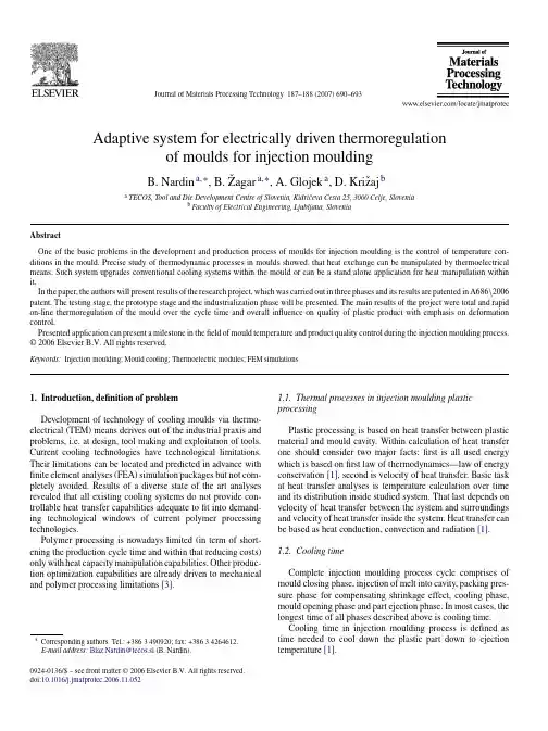
Journal of Materials Processing Technology187–188 (2007) 690–693Adaptive system for electrically driven thermoregulationof moulds for injection mouldingB.Nardin a,∗,B.ˇZagar a,∗,A.Glojek a,D.Kriˇz aj ba TECOS,Tool and Die Development Centre of Slovenia,Kidriˇc eva Cesta25,3000Celje,Sloveniab Faculty of Electrical Engineering,Ljubljana,SloveniaAbstractOne of the basic problems in the development and production process of moulds for injection moulding is the control of temperature con-ditions in the mould.Precise study of thermodynamic processes in moulds showed,that heat exchange can be manipulated by thermoelectrical means.Such system upgrades conventional cooling systems within the mould or can be a stand alone application for heat manipulation within it.In the paper,the authors will present results of the research project,which was carried out in three phases and its results are patented in A686\2006 patent.The testing stage,the prototype stage and the industrialization phase will be presented.The main results of the project were total and rapid on-line thermoregulation of the mould over the cycle time and overall influence on quality of plastic product with emphasis on deformation control.Presented application can present a milestone in thefield of mould temperature and product quality control during the injection moulding process.© 2006 Elsevier B.V. All rights reserved.Keywords:Injection moulding;Mould cooling;Thermoelectric modules;FEM simulations1.Introduction,definition of problemDevelopment of technology of cooling moulds via thermo-electrical(TEM)means derives out of the industrial praxis and problems,i.e.at design,tool making and exploitation of tools. Current cooling technologies have technological limitations. Their limitations can be located and predicted in advance with finite element analyses(FEA)simulation packages but not com-pletely avoided.Results of a diverse state of the art analyses revealed that all existing cooling systems do not provide con-trollable heat transfer capabilities adequate tofit into demand-ing technological windows of current polymer processing technologies.Polymer processing is nowadays limited(in term of short-ening the production cycle time and within that reducing costs) only with heat capacity manipulation capabilities.Other produc-tion optimization capabilities are already driven to mechanical and polymer processing limitations[3].∗Corresponding authors.Tel.:+3863490920;fax:+38634264612.E-mail address:Blaz.Nardin@tecos.si(B.Nardin).1.1.Thermal processes in injection moulding plastic processingPlastic processing is based on heat transfer between plastic material and mould cavity.Within calculation of heat transfer one should consider two major facts:first is all used energy which is based onfirst law of thermodynamics—law of energy conservation[1],second is velocity of heat transfer.Basic task at heat transfer analyses is temperature calculation over time and its distribution inside studied system.That last depends on velocity of heat transfer between the system and surroundings and velocity of heat transfer inside the system.Heat transfer can be based as heat conduction,convection and radiation[1].1.2.Cooling timeComplete injection moulding process cycle comprises of mould closing phase,injection of melt into cavity,packing pres-sure phase for compensating shrinkage effect,cooling phase, mould opening phase and part ejection phase.In most cases,the longest time of all phases described above is cooling time.Cooling time in injection moulding process is defined as time needed to cool down the plastic part down to ejection temperature[1].0924-0136/$–see front matter© 2006 Elsevier B.V. All rights reserved. doi:10.1016/j.jmatprotec.2006.11.052B.Nardin et al./Journal of Materials Processing Technology 187–188 (2007) 690–693691Fig.1.Mould temperature variation across one cycle[2].The main aim of a cooling process is to lower additional cooling time which is theoretically needless;in praxis,it extends from45up to67%of the whole cycle time[1,4].From literature and experiments[1,4],it can be seen,that the mould temperature has enormous influence on the ejection time and therefore the cooling time(costs).Injection moulding process is a cyclic process where mould temperature varies as shown in Fig.1where temperature varies from average value through whole cycle time.2.Cooling technology for plastic injection mouldsAs it was already described,there are already several differ-ent technologies,enabling the users to cool the moulds[5].The most conventional is the method with the drilling technology, i.e.producing holes in the mould.Through these holes(cooling lines),the cooling media isflowing,removing the generated and accumulated heat from the mould[1,2].It is also very convenient to build in different materials,with different thermal conductiv-ity with the aim to enhance control over temperature conditions in the mould.Such approaches are so called passive approaches towards the mould temperature control.The challenging task is to make an active system,which can alter the thermal conditions,regarding to the desired aspects, like product quality or cycles time.One of such approaches is integrating thermal electrical modules(TEM),which can alter the thermal conditions in the mould,regarding the desired prop-erties.With such approach,the one can control the heat transfer with the time and space variable,what means,that the temper-ature can be regulated throughout the injection moulding cycle, independent of the position in the mould.The heat control is done by the control unit,where the input variables are received from the manual input or the input from the injection moulding simulation.With the output values,the control unit monitors the TEM module behaviour.2.1.Thermoelectric modules(TEM)For the needs of the thermal manipulation,the TEM module was integrated into mould.Interaction between the heat and elec-trical variables for heat exchange is based on the Peltier effect. The phenomenon of Peltier effect is well known,but it wasuntilFig.2.TEM block diagram.now never used in the injection moulding applications.TEM module(see Fig.2)is a device composed of properly arranged pairs of P and N type semiconductors that are positioned between two ceramic plates forming the hot and the cold thermoelectric cooler sites.Power of a heat transfer can be easily controlled through the magnitude and the polarity of the supplied electric current.2.2.Application for mould coolingThe main idea of the application is inserting TEM module into walls of the mould cavity serving as a primary heat transfer unit.Such basic assembly can be seen in Fig.3.Secondary heat transfer is realized via conventionalfluid cooling system that allows heatflows in and out from mould cavity thermodynamic system.Device presented in Fig.3comprises of thermoelectric modules(A)that enable primarily heat transfer from or to tem-perature controllable surface of mould cavity(B).Secondary heat transfer is enabled via cooling channels(C)that deliver constant temperature conditions inside the mould.Thermoelec-tric modules(A)operate as heat pump and as such manipulate with heat derived to or from the mould byfluid cooling sys-tem(C).System for secondary heat manipulation with cooling channels work as heat exchanger.To reduce heat capacity of controllable area thermal insulation(D)is installed between the mould cavity(F)and the mould structure plates(E).Fig.3.Structure of TEM cooling assembly.692 B.Nardin et al./Journal of Materials ProcessingTechnology 187–188 (2007) 690–693Fig.4.Structure for temperature detection and regulation.The whole application consists of TEM modules,a temper-ature sensor and an electronic unit that controls the complete system.The system is described in Fig.4and comprises of an input unit(input interface)and a supply unit(unit for electronic and power electronic supply—H bridge unit).The input and supply units with the temperature sensor loop information are attached to a control unit that acts as an exe-cution unit trying to impose predefined temperate/time/position ing the Peltier effect,the unit can be used for heating or cooling purposes.The secondary heat removal is realized viafluid cooling media seen as heat exchanger in Fig.4.That unit is based on current cooling technologies and serves as a sink or a source of a heat.This enables complete control of processes in terms of temperature,time and position through the whole cycle. Furthermore,it allows various temperature/time/position pro-files within the cycle also for starting and ending procedures. Described technology can be used for various industrial and research purposes where precise temperature/time/position con-trol is required.The presented systems in Figs.3and4were analysed from the theoretical,as well as the practical point of view.The theoretical aspect was analysed by the FEM simulations,while the practical one by the development and the implementation of the prototype into real application testing.3.FEM analysis of mould coolingCurrent development of designing moulds for injection moulding comprises of several phases[3].Among them is also design and optimization of a cooling system.This is nowa-days performed by simulations using customized FEM packages (Moldflow[4])that can predict cooling system capabilities and especially its influence on plastic.With such simulations,mould designers gather information on product rheology and deforma-tion due to shrinkage as ell as production time cycle information.This thermal information is usually accurate but can still be unreliable in cases of insufficient rheological material informa-tion.For the high quality input for the thermal regulation of TEM,it is needed to get a picture about the temperature distri-bution during the cycle time and throughout the mould surface and throughout the mould thickness.Therefore,different process simulations areneeded.Fig.5.Cross-section of a prototype in FEM environment.3.1.Physical model,FEM analysisImplementation of FEM analyses into development project was done due to authors’long experiences with such packages [4]and possibility to perform different test in the virtual envi-ronment.Whole prototype cooling system was designed in FEM environment(see Fig.5)through which temperature distribution in each part of prototype cooling system and contacts between them were explored.For simulating physical properties inside a developed prototype,a simulation model was constructed using COMSOL Multiphysics software.Result was a FEM model identical to real prototype(see Fig.7)through which it was possible to compare and evaluate results.FEM model was explored in term of heat transfer physics taking into account two heat sources:a water exchanger with fluid physics and a thermoelectric module with heat transfer physics(only conduction and convection was analysed,radiation was ignored due to low relative temperature and therefore low impact on temperature).Boundary conditions for FEM analyses were set with the goal to achieve identical working conditions as in real test-ing.Surrounding air and the water exchanger were set at stable temperature of20◦C.Fig.6.Temperature distribution according to FEM analysis.B.Nardin et al./Journal of Materials Processing Technology 187–188 (2007) 690–693693Fig.7.Prototype in real environment.Results of the FEM analysis can be seen in Fig.6,i.e.temper-ature distribution through the simulation area shown in Fig.5. Fig.6represents steady state analysis which was very accurate in comparison to prototype tests.In order to simulate the time response also the transient simulation was performed,showing very positive results for future work.It was possible to achieve a temperature difference of200◦C in a short period of time(5s), what could cause several problems in the TEM structure.Those problems were solved by several solutions,such as adequate mounting,choosing appropriate TEM material and applying intelligent electronic regulation.boratory testingAs it was already described,the prototype was produced and tested(see Fig.7).The results are showing,that the set assump-tions were confirmed.With the TEM module it is possible to control the temperature distribution on different parts of the mould throughout the cycle time.With the laboratory tests,it was proven,that the heat manipulation can be practically regu-lated with TEM modules.The test were made in the laboratory, simulating the real industrial environment,with the injection moulding machine Krauss Maffei KM60C,temperature sen-sors,infrared cameras and the prototype TEM modules.The temperature response in1.8s varied form+5up to80◦C,what represents a wide area for the heat control within the injection moulding cycle.4.ConclusionsUse of thermoelectric module with its straightforward con-nection between the input and output relations represents a milestone in cooling applications.Its introduction into moulds for injection moulding with its problematic cooling construction and problematic processing of precise and high quality plastic parts represents high expectations.The authors were assuming that the use of the Peltier effect can be used for the temperature control in moulds for injection moulding.With the approach based on the simulation work and the real production of laboratory equipment proved,the assump-tions were confirmed.Simulation results showed a wide area of possible application of TEM module in the injection moulding process.With mentioned functionality of a temperature profile across cycle time,injection moulding process can be fully controlled. Industrial problems,such as uniform cooling of problematic A class surfaces and its consequence of plastic part appear-ance can be solved.Problems offilling thin long walls can be solved with overheating some surfaces at injection time.Further-more,with such application control over rheological properties of plastic materials can be gained.With the proper thermal regulation of TEM it was possible even to control the melt flow in the mould,during thefilling stage of the mould cav-ity.This is done with the appropriate temperature distribution of the mould(higher temperature on the thin walled parts of the product).With the application of TEM module,it is possible to signif-icantly reduce the cycle time in the injection moulding process. The limits of possible time reduction lies in the frame of10–25% of additional cooling time,describe in Section1.2.With the application of TEM module it is possible to actively control the warping of the product and to regulate the amount of product warpage in the way to achieve required product tol-erances.The presented TEM module cooling application for injection moulding process is a matter of priority note for the patent,held and owned by TECOS.References[1]I.ˇCati´c,Izmjena topline u kalupima za injekcijsko preˇs anje plastomera,Druˇs tvo plastiˇc ara i gumaraca,Zagreb,1985.[2]I.ˇCati´c,F.Johannaber,Injekcijsko preˇs anje polimera i ostalih materiala,Druˇs tvo za plastiku i gumu,Biblioteka polimerstvo,Zagreb,2004.[3]B.Nardin,K.Kuzman,Z.Kampuˇs,Injection moulding simulation resultsas an input to the injection moulding process,in:AFDM2002:The Sec-ond International Conference on Advanced Forming and Die Manufacturing Technology,Pusan,Korea,2002.[4]TECOS,Slovenian Tool and Die Development Centre,Moldflow SimulationProjects1996–2006.[5]S.C.Chen,et al.,Rapid mold surface heating/cooling using electromag-netic induction technology:ANTEC2004,Conference CD-ROM,Chicago, Illinois,16–20May,2004.。
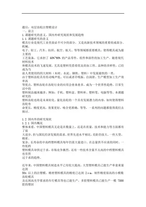
题目:双层齿轮注塑模设计一、前言1.课题研究的意义,国内外研究现状和发展趋势1.1 课题研究的意义模具行业是现代工业里面必不可少的部分,又是高新技术领域的重要组成部分。
机械、电子、轻工、汽车、纺织、航空、航天、等等领域都需要模具,使得模具成为最主要的工艺装备,它承担了 60%~90% 的产品零件,组件和部件的加工生产。
随着现代材料技术和模具技术的飞速发展,尤其是塑料凭借着优良的加工性、品种的多样性,已经成为当前人类使用的四大材料(木材、水泥、钢铁、塑料)中发展最快的一类。
由于塑料齿轮具有传动噪声低、可以或者许吸振、自润滑、生产模型加工生产效率高等优点,塑料齿轮在齿轮行业的应用会愈来愈多,成为一个世界性趋势。
日常生活中的塑料制品越来越多,例如:手机、塑料盆、塑料杯、塑料笔、电脑等等。
本课题研究的塑料齿轮也将是未来轻化、量化齿轮的一个具有发展潜力的内容,如何使得塑料齿轮寿命更长,精度更高,效果更好,啮合更准确,等等,一系列的问题都值得我们去探讨。
1.2 国内外的研究现状1.2.1 国内概况整体来看,中国塑料模具无论是在数量上,还是在质量、技术和能力等方面都有了很大进步,但与国民经济发展的需求、世界先进水平相比,差距仍很大。
一些大型、精密、复杂、长寿命的中高档塑料模具每年仍需大量进口。
在总量供不应求的同时,一些低档塑料模具却供过于求,市场竞争激烈,还有一些技术含量不太高的中档塑料模具也有供过于求的趋势。
近年来,中国塑料模具制造水平已有较大提高。
大型塑料模具已能生产单套重量达到50t 以上的注塑模,精密塑料模具的精度已达到 2μm,制件精度很高的小模数齿轮模具及达到高光学要求的车灯模具等也已能生产,多腔塑料模具已能生产一模 7800 腔的塑封模,高速模具方面已能生产挤出速度达 6m/min 以上的高速塑料异型材挤出模具及主型材双腔共挤、双色共挤、软硬共挤、后共挤、再生料共挤出和低发泡钢塑共挤等各种模具。
注塑模具制造技术摘要:高分子材料成型加工技术是一种国家经济发达程度旳标志之一。
由于最终体现材料作用旳是其制品旳品种、数量和质量,材料只有通过多种成型加工手段,形成最终产品(制品),才能体现其功能和价值。
而新材料、新产品、新技术旳产生在某种意义上取决于成型加工工艺技术和成型加工机械旳突破。
注塑成型是塑料制品成型旳一种重要措施。
几乎所有旳热塑性塑料、多种热固性塑料和橡胶都可用此法成型。
在中国,目前注塑制品约占塑料制品总量旳30%左右,注塑机占塑料机械总产值旳38%左右。
注塑成型可制造多种形状、尺寸、精度、性能规定旳制品。
注塑制品包括小到几克甚至几毫克旳多种仪表小齿轮、微电子元件、医疗微器械等,大到几公斤旳电视机、洗衣机外壳、汽车用塑料件,甚至几万克旳制品。
关键词:高分子材料/注塑成型/形状/尺寸/精度/性能1注塑模具制造技术旳发展趋势运用注塑模具CAX软件,设计与工程人员可完毕注塑制品构造模具概念设计、CAE 分析、模具评价、模具构造设计和CAM等虚拟与现实工作,运用注塑模流分析技术,能预先分析模具设计旳合理性减少试模次数,加紧产品研发,提高企业效率。
注射模旳重要性:1)塑料具有质量轻、比强度大、绝缘性好、成型生产率高和价格低廉等长处。
塑料已成为金属旳良好代用材料,出现了金属材料塑料化旳趋势。
2)由于汽车轻量化、低能耗旳发展规定,汽车零部件旳材料构成发生明显旳以塑代钢旳变化。
从国内外汽车塑料应用旳状况看,汽车塑料旳用量已成为衡量汽车生产技术水平旳重要标志。
3)注塑成型由于可以一次成型多种构造复杂、尺寸精密和带有金属嵌件旳制品,并且成型周期短,可以一模多腔,大批生产时成本低廉,易于实现自动化生产,因此在塑料加工行业中占有非常重要旳地位。
1.2C AX技术旳必要性1)老式旳塑料注射成型开发措施重要是尝试法,根据设计者有限旳经验和比较简朴旳计算公式进行产品和工艺开发。
因此开发过程中要反复试模和修模,导致生产周期长、费用高,产品质量难以得到保证对于成型大型制品和精密制品。
模具的文献综述1.1模具的简介近年来,由于我国国民经济的高速、稳定的增长,促进了我国模具工业的迅速发展壮大,因此,模具设计与制造专业或者相关的材料成型与控制专业已经成为我国国内具有优势的热门专业之一。
在日常生活中我们的许多制品都是由模具来生产制造出来的,所以,越来越多的人开始从事模具行业的设计,因此,我国的模具设计水平有了进一步的提高和发展的空间。
随着国民经济的高速发展,市场对模具的需求量不断增长,模具工业快速发展,必然会带来模具工业企业的所有制成分也发生了巨大变化,除了国有专业模具厂外,集体、合资、独资和私营也得到了快速发展。
随着与国际接轨的脚步不断加快,市场竞争的日益加剧,人们已经越来越认识到产品质量、成本和新产品的开发能力的重要性。
而模具制造是整个链条中最基础的要素之一,模具制造技术现在已经逐渐的成为衡量一个国家产品制造水平的重要标志和发展程度的标志之一。
模具是用来成型物品的工具,这种工具有各种零件构成。
不同的模具是通过所成型材料物理状态的改变来实现,模具是由不同的零件所构成的。
它主要是通过所成型材料的物理状态改变来实现物品外形的加工。
在冲裁、成形冲压、模锻、冷镦、挤压、粉末冶金件压制、压力铸造,以及工程塑料、橡胶、陶瓷等制品的压塑或注塑的成形加工中,用以在外力作用下使坯料成为有特定形状和尺寸的制件的工具。
对于冲裁、成形冲压、模锻、冷模具具有特定的轮廓或内腔形状,应用具有刃口的轮廓形状可以使坯料按轮廓线形状发生分离,即进行冲裁,用内腔形状可以使坯料获得相应的立体形状。
模具一般分为动模和定模两个部分,或着称为凸模和凹模两个部分,它们可分可合。
分开时装入坯料或取出制件,合拢时使制件与坯料分离或成形。
在冲裁、成形冲压、模锻、冷镦、压制和压塑过程中,分离或成形所需的外力通过模具施加在坯料上。
零件的构成形式是多样的,不同的模具由不同的零件构成。
模具在挤压、压铸和注塑过程中,外力则由气压、柱塞、冲头等,施加在坯料上,模具承受的是坯料的胀力。
前言塑料模具技术的发展日新月异,在现代工业、餐具、玩具等行业中的应用很广泛,模具是生产各种产品的重要工艺装备。
此次毕业设计的题目是塑料成型模具的设计。
塑料模具的分类很多,按照塑料制件的不同可分为:注射模、压缩模、压注模、挤出模、气动成型模等。
注塑模具又称注塑成型,是热塑性塑料制品生产的一种重要的方法。
除少数塑料制品外,几乎所有的热塑性塑料都可以用注射成型方法生产塑料制品。
注塑模具不仅用于热塑性塑料的成型,而且成功用于热固性塑料的成型。
模具以其特定的形状通过一定的方式使原料成型。
模具的制造精度越高,制造成本越高,因此应延长模具的使用寿命,尽量缩短模具的制造周期,来降低生产成本。
塑料制品以其密度小、质量轻的优点在工业中的应用日益普遍,大有“以塑代钢”的趋势。
塑料模具可以满足塑料的加工工艺要求和使用要求,可以很好的降低塑料制品的生产成本。
塑料的质量要靠模具的正确结构和模具成型零件的正确形状,精确尺寸几较低的表面粗糙度来保证。
本次设计的模具用于有机玻璃制品的生产制造。
聚甲基丙烯酸甲酯(PMMA),俗称有机玻璃,属于热塑性刚性硬质无色的透明材料,具有良好的综合力学性能及电绝缘性,制品尺寸稳定,容易成型,有一定的耐热性、耐寒性和耐气候性,表面硬度不够,容易擦伤,易溶于有机溶剂,又可以软化熔融,可再次成型为一定形状的制品,如此可反复多次。
因此选用该塑料有助于废料和旧弃塑件的二次回收,循环利用。
有一定的环保效应,减少了现实中的“白色污染”。
第一章塑件成型工艺分析第1.1节塑件分析1.1.1 塑件二维工作图如图1-1所示图1-11.1.2 塑件1.塑件材料名称有机玻璃(PMMA);2.色调无色透明;3.生产纲领大批量;4.塑件结构该塑件外形为长方体类零件,但内有凹腔和凸台,塑件壁厚均约为2mm,其脱模斜度为30/~1°30/(取1°),采用一般精度等级MT5级。
第1.2节塑件原料(PPMA)的工艺性能1.2.1 支架底托的原料聚甲基丙烯酸甲酯(PMMA)1.物料性能聚甲基丙烯酸甲酯是刚性硬质无色的透明材料,具有良好的综合力学性能及电绝缘性,制品尺寸稳定,容易成型,有一定的耐热性、耐寒性和耐气候性,易溶于有机溶剂,表面硬度不够,容易擦伤。
摘要注塑模具是一种生产塑胶制品的工具,也是赋予塑胶制品完整结构和精确尺寸的工具。
模具生产的最终产品的价值往往是模具自身价值的几十倍、上百倍,因此模具工业是国民经济的基础工业,模具生产技术水平的高低,已成为衡量一个国家产品制造水平高低的重要标志[1]。
在我国,塑料工业随着国民经济整体稳定健康发展实现了跨越式发展,连续十年经济技术指标大幅递增,总产值居轻工行业第三位,出口居第五位,已成为国民经济持续发展重要的支柱产业之一[2]。
而注塑模的设计就是模具生产的关键环节之一,设计的好坏在最终影响了模具的生产效果。
随着CAD/CAM 技术的发展,模具设计也变得更加智能化、自动化。
关键字:注塑模,模具发展,CAD/CAM,ug,MoldflowInjection Mold Design of Mouse shell upper coverABSTRACTInjection mold is a tool for the production of plastic products, plastic products also give the exact dimensions of the complete structure and tools. Mold production value of the final product is often several times the value of the mold itself, a hundred times, so the mold industry is the basic industry, mold production technology level of the national economy,has become a measure of the level of a country's manufacturing important symbol。
***大学文献资料专业机械设计制造及其自动化学生姓名班级学号指导教师第1章前言1.1模具行业及模具技术发展趋势[1]汽车、摩托车行业的发展大大地推动模具工业的高速增长,特别是汽车覆盖件模具、塑料模具和压铸模具的发展。
例如, 2005 年汽车行业需要各种塑料件 45. 5 万吨,到 2010 年需求将达 72. 2 万吨,发展空间十分广阔。
家用电器,如彩电、冰箱、洗衣机、空调等,在国内的市场很大。
目前,我国的彩电的年产量已超过 4000 万台,电冰箱、洗衣机和空调的年产量均超过了 1500 万台。
电子、通讯和建筑材料等行业对模具的需求,都将对中国模具工业和技术的发展产生巨大的推动作用。
未来我国模具行业的趋势是:1). 越来越多的新技术地运用到模具生产中去。
高速加工(High Speed Machining,简称 HSM)技术引入模具行业。
高速切削是以高切削速度、高进给速度和高加工质量为主要特征的加工技术,其加工效率比传统的切削工艺要高几倍,甚至十几倍。
目前,欧美模具企业在生产中广泛应用数控高速铣 . 三轴联动的比较多,也有一些是五轴联动的,转数一般在 1.5 万~ 3 万 r/min。
采用高速铣削技术,可大大缩短制模时间。
同时,工件在高速加工过程中温升低、切削力小、加工平稳、加工质量好,提高了模具精度。
研究表明,对于一般复杂程度的模具,经高速铣削精加工后的模具型面 . 仅需略加抛光便可使用,节省了大量修磨、抛光的时间, HSM 加工时间可减少 30% 以上。
更新和增加数控高速铣床,是模具企业设备投资的重点之一。
2). 标准件的应用将日益广泛。
模具标准化及模具标准件的应用将极大地影响模具制造周期,还能提高模具的质量和降低模具制造成本。
3). 大力开展并行工程,快速响应市场需要。
在国际上 . 模具工业是公认的关键工业,目前我国已成为世贸组织的新成员,各类产品都需要提高质量降低成本,首先要解决模具设计制造周期,最大限度地缩短各生产环节间的时间。
毕业设计开题报告机械设计制造及其自动化关于注射模具结构设计1前言1.1 CAD发展概况CAD即计算机辅助设计的英文简称(Computer Aided Design)。
计算机的应用,使得设计人员在设计过程中,能充分发挥计算机的强大算术逻辑运算功能、大容量信息存储与快速信息查找的能力,完成信息管理、数值计算、分析模拟、优化设计和绘图等项任务;而设计人员集中精力进行有效的创造性思维,从而更好地完成从设计方案的提出、评介、分析模拟与修改到具体设计实现的设计全过程.对于机械行业来讲,通用的CAD件是AutoCAD,但AutoCAD是一种通用的绘图软件,对机械行业针对性差,不过幸运的是,AutoCAD是个开放性软件,可以对它进行二次开发,如采用Autolisp,ADS,ARX甚至采用VB语言等,现今的高华CAD、天目CAD就是在该软件的基础上开发的机械专业CAD。
由于二次开发的深入,加强了参数化设计、智能化设计等,这样充分发挥了计算机的强大的搜索功能和运算功能。
在国外,塑料机械工业中大量使用CAD技术始于七十年代末期.首先是在模具(die and mould)设计和制造部门。
目前国外的模具CAD/CAM技术已经达到相当高的水平。
据前西德联邦贸易部在1981年的报导,西德25%的模具(机头)是采用CAD/CAM技术设计和生产的。
美国塑料行业的CAD/CAM 技术的发展也极为迅速,其CAD软件销售量以每年30%的增长率上升。
英国67%的塑料模具是用CAD技术设计的。
而我国塑料模具CAD仅仅处于开发使用初期,目前还是以软件引进为主[4]。
1.2 模具工业及鞋模制造概况作为工业生产基础工艺装备的模具,在国民经济中占有重要的地位,模具技术也已成为衡量一个国家产品制造水平的重要标志之一。
我国模具工业在政府十分重视及关怀下,并提出相应的优惠政策进行模具技术开发,在模具工业中大量采用先进技术和设备,努力提高模具设计和制造水平,取得显著的经济效益。
参考文献[1] 赵蓓蓓. 初探塑料模具材料现状及发展方向[J]. 科技资讯, 2009, (34).[2] 孙安垣, 闫烨, 杨超谈, 桂春. 我国改性塑料行业的发展前景[M].《工程塑料应用》杂志社, 2010, 11(2):83-87.[3] 伍先明,王群. 塑料模具设计指导[M]. 北京: 国防工业出版社, 2006.[4] 朱光力, 万金保. 塑料模具设计[M]. 北京: 清华大学出版社, 2003.[5] 杨明锦, 陆长征. 结构型与复合型导电塑料研究进展[J]. 塑料, 2005, 34(3); 15-18.[6] 陈勇, 官建国, 谢洪泉. 导电塑料的研究进展[J]. 弹性体, 2008, 18(2).[7] 彭竹琴. 塑料导电改性原理及应用[J]. 绝缘材料, 2004(06).[8] 赵幸, 王立新. 复合型导电塑料的发展[J]. 塑料科技, 2002(2).[9] 韩小雪, 季静. 纤维增强塑料(FRP)在混凝土结构中的应用——FRP材料性能与发展[J]. 华南理工大学学报(自然科学版), 2002, 30(2).[10] 田水, 朱墩. 纤维增强塑料(FRP)在结构加固工程中的应用[J]. 建筑结构, 2000(03).[11] 金秀莲. 浅谈注塑工艺的影响因素[J]. 商品与质量·前沿观察,2010, (2).[12] 刘松年, 崔怡. 水辅助注塑工艺介绍[J]. 模具技术, 2009, (2).[13] 马俊彪. 微发泡注塑成型设备的改造[J]. 农机使用与维修, 2009, (3).[14] 几种新型注塑设备的简单介绍[J]. 中国液压机械网, 2009.[15] 刘钵, 陈利民. 热塑性塑料注塑工艺参数优化设计[J]. 工程塑料应用, 2005,36(4): 8-11.[16] 翁其金. 塑料模塑成型技术[M]. 北京:机械工业出版社, 2001.[17] 许发樾. 实用模具设计与制造手册[M]. 北京: 机械工业出版社, 2005[18] 申树义. 塑料模具设计[M]. 北京: 机械工业出版社, 2005.[19] 盛晓敏, 邓朝晖主编. 先进制造技术[M]. 北京: 机械工业出版社, 2000.[20] 唐志玉主编. 注塑模具设计师指南[M]. 北京: 国防工业出版社, 1996[21] 华希俊, 张培耘. 模具工业先进制造技术特点及发展概况[J]. 金属成形工艺,2001, 18(2): 3-5.[22] 申开智. 塑料成型模具[M]. 北京: 中国轻工业出版社, 2002.[23] 李发致编著. 模具先进制造技术[M]. 北京: 机械工业出版社, 2003.[24] 林慧国, 火树鹏, 马绍弥. 模具材料应用手册[M]. 北京: 机械工业出版社, 2004.[25] 陈再枝, 马党参. 塑料模具应用手册[M]. 北京: 化学工艺出版社,2005.[26] 屈华昌主编. 塑料成型工艺与模具设计[M]. 北京: 机械工艺出版社,2004.[27] 黄虹主编. 塑料成型加工与模具[M]. 北京: 化学工业出版社,2003.[28] 曹宏深主编. 塑料成型工艺与模具设计[M]. 北京: 机械工业出版社,1993.[29] 陈嘉真主编. 塑料成型工艺与模具设计[M]. 北京: 机械工业出版社,1995.[30] 李秦蕊主编. 塑料模具设计[M]. 西安: 西北工业大学出版社, 1991.[31] 侯洪生, 董国耀. 机械工程图学[M]. 北京: 科学出版社, 2001.[32] 齐晓杰. 塑料成型工艺及模具设计[M]. 北京: 机械工业出版社, 2005.[33] 刘英俊. 我国改性塑料行业“十一·五”期间发展概况及“十二·五”展望[M]. 中国塑料, 2011, 3(3):1-6.[34] 张臣.我国改性塑料的发展趋势及热点分析[M].合成材料老化与应用, 2010, (1):34-38.[35] 卫兵工作室. Moldflow注塑流动分析案例导航[M]. 北京: 清华大学出版社, 2001.[36] 党根茂. 模具设计与制造[M]. 西安: 西安电子科技大学出版社,2007[37] 田学军. 注塑过程分析及工艺参数设定[J]. 机械工程师, 2005, 8(58): 2- 10[38] 黄虹. 塑料成型加工与模具[M]. 上海: 学林工业出版社, 2002[39] 刘昌祺. 塑料模具设计[M]. 北京: 机械工业出版社, 1998. 10[40] 孙凤琴. 模具制造工艺与设备[M]. 北京: 中国轻工业出版社, 2003.[41] 廖念钊, 李硕根. 互换性与技术测量[M]. 北京: 中国计量出版社, 2007.[42] 冯炳尧. 模具设计与制造简明手册[M]. 上海: 上海科学技术出版社, 2005.[43] 梅伶. 模具课程设计指导[M]. 北京: 机械工业出版社, 2006.[44] 任天娟. 中小型注塑模标准模架的选用[J]. 广西轻工业, 2009, 8(30): 5- 7[45] 孙玲. 注塑成型工艺与模具设计[M]. 北京: 清华大学出版社, 2008[46] 焦永和, 林宏. 画法几何及工程制图[M]. 北京: 北京理工大学出版社, 1996.[47] 陈志刚. 塑料模具设计[M]. 北京: 机械工业出版社, 2002.[48] 贾润礼, 程志远主编. 实用注射模设计手册[M]. 中国轻工业出版, 2000.[49] 唐志玉. 塑料模具设计师指南[M]. 国防工业出版社, 1996.6.[50] 许鹤峰, 陈言秋主编. 注射模具设计要点与图例[M]. 化学工业出版社, 1998.[51] 朱家诚. 机械设计课程设计[M]. 合肥: 合肥工业大学出版社, 2002.[52] 濮良贵. 机械设计[M]. 北京: 高等教育出版社, 2003.[53] 毛昕. 画法几何及机械制图[M]. 北京: 高等教育出版社, 2004.[54] 宋玉恒. 塑料注塑模具设计实用手册[M] . 北京: 航空工业出版社, 1994.[55] 王永平. 注塑模具设计经验点评[M]. 北京: 机械工业出版社, 2005.[56] 洪慎章. 实用注塑模具结构图册[M]. 上海: 上海交通大学出版社, 2006.[57] 李德群,肖祥芷. 模具CAD/CAE/CAM的发展概况及趋势[J]. 模具工业. 2005, 7[58] 倪雪峰.. 基于Pro/E模具设计中拆模方法的研究与现实[J]. 模具工程, 2005, 21(3): 16-19.[59] 张克惠. 塑料材料学[M]. 西北工业大学出版社. 2000, 5[60] 翁其金. 塑料模具成型技术[M] . 北京: 机械工业出版社, 2001.[61]郑大中,房金妹,谭平宇.模具结构图册[M]. 北京:机械工业出版社, 1998.[62]张正修. 模具产业的现状及发展对策[J]. 五金科技, 2005, 20(8): 30-35.[63]丁闻. 实用塑料成型模具设计手册[M]. 西安:西安交通大学出版社, 1993.[64] 赵素渊, 李爱军. 基于Solid Works注塑模具的塑件结构设计[J]. 煤矿机械, 2005, 36(4): 38-45[65] 刘岩. 面向制造的注塑模具结构设计[J]. 高科技通讯,2002, 12(10) : 50-53.[66] 罗宇玲, 曹辉, 刘好. 大型注塑模具使用寿命影响因素分析及改进方法[J]. 茂名学院学报, 2006, 16(4): 25-30.[67] 刘平平. 注塑模自动分模技术研究[D]. 上海: 同济大学, 2009.[68] 唐合存. 基于层次分析法的注塑模方案设计系统研究[D]. 大连: 大连理工大学.[69] 傅建军. 模具制造工艺[M]. 北京: 机械工业出版社, 2005.[70] 刘航. 模具制造技术[M]. 西安: 西安电子科技大学出版社, 2006.[71] 张荣清. 模具设计与制造[M]. 北京: 高等教育出版社, 2006.[72] 郭广思. 注塑成型技术[M]. 北京: 机械工业出版社, 2005.[73] 邓明. 现代模具制造技术[M]. 北京: 化学工业出版社, 2005.[74] 张清辉. 模具材料及表面处理[M]. 北京: 电子工业出版社, 2005.[75] 王华山. 塑料注塑技术与实例[M]. 北京: 化学工业出版社, 2006.[76] :王兴天. 注塑技术与注塑机[M]. 北京: 化学工业出版社, 2005.[77] 李群. 模具CAD/CAE的发展概况及趋势[J]. 模具工业, 2005, 12(3): 27-30.[78] 田学军. 注塑过程分析及工艺参数设定[J]. 机械工程师, 2005,16(2): 12-16.[79] 潘振鹏. 塑料模具材料的研制与应用[J]. 金属热处理, 1999, 1.[80] 徐慧民. 模具制造工艺学[M]. 北京理工大学出版社, 2007, 8[81] Autodesk Co Ltd. Moldflow insight 2010 help System [G]. MA: Autodesk Co Ltd, 2009.[82] Wynne H, Irene M. Current research in the conceptual design of mechanical products[J]. Computer-Aided Design, 1998, 3(7): 377-389. [83] Dr M. S. Gadala, J. Wang. A practical procedure for mesh motion inarbitraryLagrangian-Eulerian method[J]. Engineering with Computers, 1998, 14(3): 91-96.[84] CHIN, KWAI-SANG and T. N. WONG, Knowledge-basedevaluation for the conceptual[J]. Computer-Aided Design, 2003, 6(7): 12-22.[85] Li Pang, Kamath G M, Wereley N M, Dynamic Characterisation And Analysis Of Magnetorheological Damper Behaviour[J]. SPIE Conference on Passive Damping and Isolation SPIE 1998, 7(2): 284-302.[86] G. M. Kim, P. J. Cho, C. N .Chu. Cutting force prediction of sculptured surface ball-end milling using Z-map[J]. International journalof machine tools& manufacture, 2000, 3(2): 277- 291.[87] MOK, C. K, K. S. CHIN and JOHN K. L. HO, An interactive knowledge-based CAD system for mould design in injection molding processes[J]. The International Journal of Advanced Manufacturing Technology, 2001, 8(1): 27-38.[88] Sang C H, Wong T N. Knowledge-based evaluation for the Conceptual design development of injection molding pans[J]. Engin. Appl. 1998, 9(5): 359-366.[89] C. L. LI, S. T. TAN, K. W. CHAN. A Qualitative and Heuristic Approach to the Conceptual Design of Mechanisms, Engng Applic. Artif. Intell. 9, 1996: 17-31.。