调节阀选型数据表
- 格式:xls
- 大小:41.00 KB
- 文档页数:1
1、流量系数计算公式表示调节阀流量系数的符号有C、Cv、Kv等,它们运算单位不同,定义也有不同。
C-工程单位制(MKS制)的流量系数,在国内长期使用。
其定义为:温度5-40℃的水,在1kgf/cm2(0.1MPa)压降下,1小时内流过调节阀的立方米数。
Cv-英制单位的流量系数,其定义为:温度60℃F (15.6℃)的水,在1b/in2(7kpa)压降下,每分钟流过调节阀的美加仑数。
Kv-国际单位制(SI制)的流量系数,其定义为:温度5-40℃的水,在10Pa(0.1MPa)压降下,1小时流过调节阀的立方米数。
注:C、Cv、Kv之间的关系为Cv=1.17Kv,Kv=1.01C 国内调流量系数将由C系列变为Kv系列。
(1)Kv值计算公式(选自《调节阀口径计算指南》)①不可压缩流体(液体)(表1-1)Kv值计算公式与判不式(液体)低雷诺数修正:流经调节阀流体雷诺数Rev小于104时,其流量系数Kv需要用雷诺数修正系数修正,修正后的流量系数为:在求得雷诺数Rev值后可查曲线图得FR值。
计算调节阀雷诺数Rev公式如下:关于只有一个流路的调节阀,如单座阀、套筒阀,球阀等:关于有五个平行流路调节阀,如双座阀、蝶阀、偏心施转阀等文字符号讲明:P1--阀入口取压点测得的绝对压力,MPa;P2--阀出口取压点测得的绝对压力,MPa;△P--阀入口和出口间的压差,即(P1-P2),MPa;Pv--阀入口温度饱和蒸汽压(绝压),MPa;Pc--热力学临界压力(绝压),MPa;F F--液体临界压力比系数,F R--雷诺数系数,依照ReV值可计算出;F L--液体压力恢复系数QL--液体体积流量,m3/h P L--液体密度,Kg/cm3ν--运动粘度,10-5m2/s W L--液体质量流量,kg/h,②可压缩流体(气体、蒸汽)(表1-2)Kv值计算公式与判不式(气体、蒸气)表1-2文字符号讲明:X-压差与入口绝对压力之比(△P/P1);X T-压差比系数;K-比热比;Qg-体积流量,Nm3/hWg-质量流量,Kg/h; P1-密度(P1,T1条件),Kg/m3T1-入口绝对温度,K;M-分子量;Z-压缩系数;Fg-压力恢复系数(气体);f(X,K)-压差比修正函数; P1-阀入口取压点测得的绝对压力,MPa;PN-标准状态密度(273K,1.0.13×102kPa),Kg/Nm3;③两相流(表1-3)Kv值计算公式(两相流)表1-3。
调型调节阀的计算选型是指在选用调节阀时,通过对流经阀门介质的参数进行计算,确定阀门的流通能力,选择正确的阀门型式、规格等参数,包括公称通径,阀座直径,公称压力等,正确的计算选型是确保调节阀使用效果的重要环节。
1.调节阀流量系数计算公式 1.1 流量系数符号:Cv —英制单位的流量系数,其定义为:温度60°F (15.6℃)的水,在16/in 2(7KPa)压降下,每分钟流过调节阀的美加仑数。
Kv —国际单位制(SI 制)的流量系数,其定义为:温度5~40℃的水,在105Pa 压降下,每小时流过调节阀的立方米数。
注:Cv ≈1.16 Kv1.2 不可压缩流体(液体)Kv 值计算公式式中:P 1—阀入口绝对压力KPa P 2—阀出口绝对压力KPaQ L —液体流量 m 3/h ρ—液体密度g/cm 3 F L —压力恢复系数,与调节阀阀型有关,附后 F F —流体临界压力比系数,C V F P P F /28.096.0-=P V —阀入口温度下,介质的饱和蒸汽压(绝对压力KPa ) P C —物质热力学临界压力(绝对压力KPa )注:如果需要,本公司可提供部分介质的P V 值和P C 值 1.2.2 高粘度液体Kv 值计算当液体粘度过高时,按一般液体公式计算出的Kv 值误差过大,必须进行修正,修正后的流量系数为RV F K VK='式中:K ′V—修正后的流量系数 K V —不考虑粘度修正时计算的流量系数 F R —粘度修正系数 (FR 值从F R ~Rev 关系曲线图中确定)计算雷诺数Rev 公式如下:对于只有一个流路的调节阀,如单座阀、套筒阀、球阀等:VL L K F Q v 70700Re =对于有二个平行流路的调节阀,如双座阀,蝶阀,偏心旋转阀等:VL L K F VQ v 49490Re =值计算式中:P 1—阀入口绝对压力KPa P 2—阀出口绝对压力KPaQg —气体流量 Nm 3/h G —气体比重(空气=1)t —气体温度℃ Z —高压气体(PN >10MPa )的压缩系数 注:当介质工作压力≤10MPa 时,Z=1;当介质工作压力>10MPa 时,Z >1,具体值查有关资料。
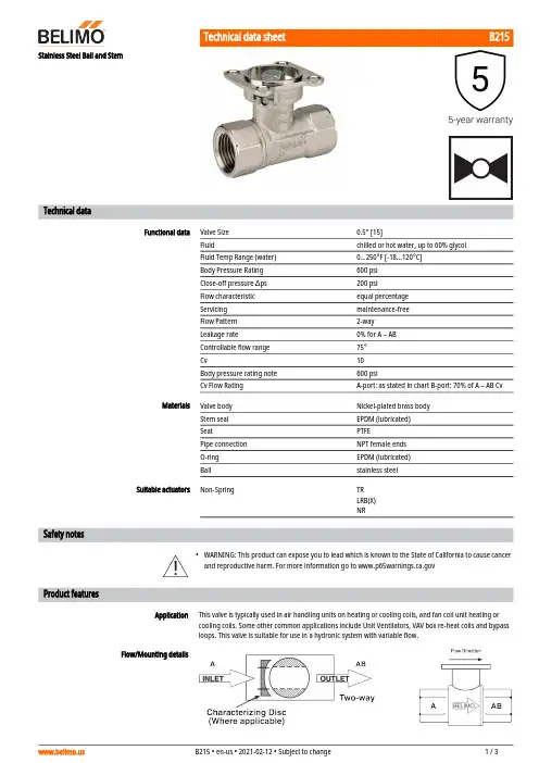
B215•ApplicationStainless Steel Ball and StemTechnical dataFunctional dataValve Size 0.5" [15]Fluidchilled or hot water, up to 60% glycol Fluid Temp Range (water)0...250°F [-18...120°C]Body Pressure Rating 600 psi Close-off pressure ∆ps 200 psiFlow characteristic equal percentage Servicing maintenance-free Flow Pattern 2-way Leakage rate0% for A – AB Controllable flow range 75°Cv10 Body pressure rating note 600 psiCv Flow RatingA-port: as stated in chart B-port: 70% of A – AB Cv MaterialsValve body Nickel-plated brass body Stem seal EPDM (lubricated)SeatPTFEPipe connection NPT female ends O-ring EPDM (lubricated)Ballstainless steel Suitable actuatorsNon-SpringTR LRB(X)NRSafety notesWARNING: This product can expose you to lead which is known to the State of California to cause cancer and reproductive harm. For more information go to Product featuresThis valve is typically used in air handling units on heating or cooling coils, and fan coil unit heating or cooling coils. Some other common applications include Unit Ventilators, VAV box re-heat coils and bypass loops. This valve is suitable for use in a hydronic system with variable flow.Flow/Mounting detailsB215 DimensionsDimensional drawingsLRB, LRXA B C D E F H1H29.4" [239] 2.4" [60] 5.6" [141] 5.0" [127] 1.3" [33] 1.3" [33] 1.2" [30] 1.1" [28]TRA B C D E F3.7" [95] 2.4" [60] 5.2" [132]4.6" [117] 1.3" [33] 1.3" [33]TFRB, TFRXA B C D E F6.6" [167] 2.4" [60] 6.1" [154] 5.5" [140] 1.5" [39] 1.5" [39]LFA B C D E F7.9" [200] 2.4" [60] 6.1" [154] 5.5" [140] 1.8" [46] 1.8" [46]ARB N4, ARX N4, NRB N4, NRX N4A B C D E F11.4" [289] 2.4" [60]7.7" [196]7.0" [179] 3.1" [80] 3.1" [80]B215TFRB, TFRXA B C D E F6.6" [167] 2.4" [60] 6.1" [154] 5.5" [140] 1.5" [39] 1.5" [39]ARB N4, ARX N4, NRB N4, NRX N4A B C D E F11.4" [289] 2.4" [60]7.7" [196]7.0" [179] 3.1" [80] 3.1" [80]LRB24-3-S•••••On/Off, Floating Point, Non-Spring Return, 24 VTechnical dataElectrical dataNominal voltageAC/DC 24 V Nominal voltage frequency 50/60 Hz Power consumption in operation 1.5 W Power consumption in rest position 0.2 WTransformer sizing 2.5 VA (class 2 power source)Auxiliary switch1 x SPDT, 3 A resistive (0.5 A inductive) @ AC 250 V, adjustable 0...100%Switching capacity auxiliary switch 3 A resistive (0.5 A inductive) @ AC 250 V Electrical Connection 18 GA plenum cable, 3 ft [1 m], with 1/2" conduit connectorOverload Protectionelectronic thoughout 0...90° rotation Functional dataInput Impedance 600 ΩDirection of motion motor selectable with switch 0/1Manual override external push button Angle of rotation 90°Angle of rotation note adjustable with mechanical stop Running Time (Motor)90 s Noise level, motor 35 dB(A)Position indicationMechanically, pluggable Safety dataDegree of protection IEC/EN IP54Degree of protection NEMA/UL NEMA 2 UL Enclosure Type 2Agency ListingcULus acc. to UL60730-1A/-2-14, CAN/CSAE60730-1:02, CE acc. to 2014/30/EU and 2014/35/EU; Listed to UL 2043 - suitable for use in air plenums per Section 300.22(c) of the NEC and Section 602.2 of the IMC Quality Standard ISO 9001Ambient temperature -22...122°F [-30...50°C]Storage temperature -40...176°F [-40...80°C]Ambient humidity max. 95% r.H., non-condensing Servicingmaintenance-free WeightWeight1.4 lb [0.60 kg]Safety notesWeather shield - PC w/ foam seal 16x8-3/8x4" (LxWxD).Battery Back Up System for SY(7~10)-110120 to 24 VAC, 40 VA transformer.12VDC 1.2 AH battery (2 required).PC Tool computer programming interface, serial port.LRB24-3-S Electrical installationINSTALLATION NOTESProvide overload protection and disconnect as required.Actuators may be connected in parallel. Power consumption and input impedance must be observed.Actuators may also be powered by 24 VDC.Actuators Hot wire must be connected to the control board common. Only connect common to neg. (-) legof control circuits. Terminal models (-T) have no-feedback.Actuators with plenum cable do not have numbers; use color codes instead.One built-in auxiliary switch (1x SPDT), for end position indication, interlock control, fan startup, etc.Apply only AC line voltage or only UL-Class 2 voltage to the terminals of auxiliary switches. Mixed orcombined operation of line voltage/safety extra low voltage is not allowed.Meets cULus requirements without the need of an electrical ground connection.Warning! Live Electrical Components!During installation, testing, servicing and troubleshooting of this product, it may be necessary to workwith live electrical components. Have a qualified licensed electrician or other individual who has beenproperly trained in handling live electrical components perform these tasks. Failure to follow all electricalsafety precautions when exposed to live electrical components could result in death or serious injury.On/Off Floating PointFloating Point - Triac Source Floating Point - Triac SinkAuxiliary Switches。
调节阀选型指南之—弹簧范围的选择一、“标准弹簧范围”的错误说法应予纠正弹簧是气动调节阀的主要零件。
弹簧范围是指一台调节阀在静态启动时的膜室压力到走完全行程时的膜室压力,字母用Pr表示。
如Pr为20~100KPa,表示这台调节阀静态启动时膜室压力是20KPa,关闭时的膜室压力是100KPa。
常用的弹簧范围有20~100KPa、20~60KPa、60~100KPa、60~180KPa、40~200KPa…由于气动仪表的标准信号是20~100KPa,因此传统的调节阀理论把与气动仪表标准信号一致的弹簧范围(20~100KPa)定义成标准弹簧范围。
调节阀厂家按20~100KPa作为标准来出厂,这是十分错误的。
为了保证调节阀正常关闭和启动,就必须用执行机构的输出力克服压差对阀芯产生的不平衡力,我们知道对气闭阀膜室信号压力首先保证阀的关闭到位,然后再继续增加的这部分力,才把阀芯压紧在阀座上克服压差把阀芯顶开。
我们又知道,不带定位器调节阀的最大信号压力是100KPa,它所对应的20~100KPa的弹簧范围只能保证阀芯走到位,再也没有一个克服压差的力量,阀门工作时必然关不严造成内漏。
为此,就必须调整或改变弹簧范围,但是,把它说成“标准弹簧范围”就出问题了,因为是标准就不能改动。
如果我们坚持标准,按“标准弹簧范围”来调整,那么,它又怎么能投用呢?在现实中,却有许多使用厂家和安装公司;都坚持按“标准弹簧范围”20~100KPa来调整和验收调节阀,又确实发生阀门关不严的问题。
错误的根源就在此。
正确的提法应该是“设计弹簧范围”,是我们设计生产弹簧的零件参数。
工作时根据气开气闭还要作出相应的调整,我们称为工作弹簧范围。
仍以上述为例,设计弹范围20~100KPa,对气闭阀我们可以将工作弹簧范围调到10~90KPa,这样就有10KPa,作用在膜室的有效面积Ae 上;又如气开阀,有气打开,无气时阀关闭,此时克服压差靠的是弹簧的预紧力。
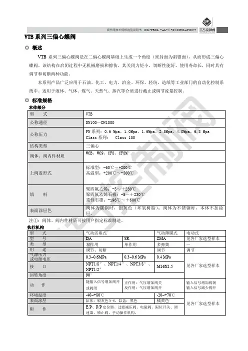
调节阀技术规格选型说明书CONTROL VALVE SPECIFICATIONSVTB系列三偏心蝶阀◎概述VTB系列三偏心蝶阀是在二偏心蝶阀基础上生成一个角度(密封面为斜锥面),从而形成三偏心蝶阀。
该结构在启闭过程中无机械磨损和擦伤,其关闭力矩小、切断性能好、使用寿命长,同时具有调节和切断两种功能。
本系列产品广泛应用于石油、化工、电力、冶金、环保、轻纺、造纸等工业部门的自动化控制系统中。
适用于液体、气体、煤气、天然气、蒸汽等介质进行截止或调节流量控制。
调节阀技术规格选型说明书CONTROL VALVE SPECIFICATIONS·2 ·调节阀技术规格选型说明书 CONTROL VALVE SPECIFICATIONS· 3 ·表1-2本体部分材质:不锈钢调节阀技术规格选型说明书CONTROL VALVE SPECIFICATIONS ◎表5 法兰标准、外形尺寸及重量表5-1:法兰标准注:B*开档尺寸可按用户要求定制。
·4 ·调节阀技术规格选型说明书CONTROL VALVE SPECIFICATIONS表5-3:气动活塞式蝶阀外形尺寸及重量Array·5 ·调节阀技术规格选型说明书CONTROL VALVE SPECIFICATIONS注:表中重量为阀体部位的重量,公称压力为PN16。
注:B*开档尺寸可按用户要求定制。
·6 ·调节阀技术规格选型说明书 CONTROL VALVE SPECIFICATIONS· 7 ·表5-5:气动薄膜式蝶阀外形尺寸及重量(法兰式)调节阀技术规格选型说明书CONTROL VALVE SPECIFICATIONS 表5-6:气动单作用活塞式蝶阀外形尺寸及重量(法兰式)注:表中重量为阀体部位的重量,公称压力为PN16。
注:B*开档尺寸可按用户要求定制。

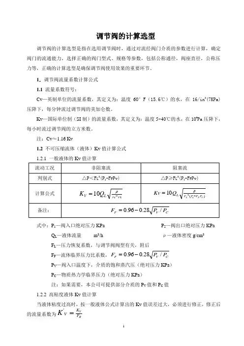
调节阀的计算选型调节阀的计算选型是指在选用调节阀时,通过对流经阀门介质的参数进行计算,确定阀门的流通能力,选择正确的阀门型式、规格等参数,包括公称通径,阀座直径,公称压力等,正确的计算选型是确保调节阀使用效果的重要环节。
1.调节阀流量系数计算公式 1.1 流量系数符号:Cv —英制单位的流量系数,其定义为:温度60°F (15.6℃)的水,在16/in 2(7KPa)压降下,每分钟流过调节阀的美加仑数。
Kv —国际单位制(SI 制)的流量系数,其定义为:温度5~40℃的水,在105Pa 压降下,每小时流过调节阀的立方米数。
注:Cv ≈1.16 Kv1.2 不可压缩流体(液体)Kv 值计算公式式中:P 1—阀入口绝对压力KPa P 2—阀出口绝对压力KPaQ L —液体流量 m 3/h ρ—液体密度g/cm 3 F L —压力恢复系数,与调节阀阀型有关,附后 F F —流体临界压力比系数,C V FP P F /28.096.0-=P V —阀入口温度下,介质的饱和蒸汽压(绝对压力KPa ) P C —物质热力学临界压力(绝对压力KPa )注:如果需要,本公司可提供部分介质的P V 值和P C 值 1.2.2 高粘度液体Kv 值计算当液体粘度过高时,按一般液体公式计算出的Kv 值误差过大,必须进行修正,修正后的流量系数为R VF K V K ='式中:K ′V—修正后的流量系数 K V —不考虑粘度修正时计算的流量系数 F R —粘度修正系数 (FR 值从F R ~Rev 关系曲线图中确定)计算雷诺数Rev 公式如下:对于只有一个流路的调节阀,如单座阀、套筒阀、球阀等:VL L K F Q v 70700Re =对于有二个平行流路的调节阀,如双座阀,蝶阀,偏心旋转阀等:VL L K F VQ v 49490Re =值计算式中:P 1—阀入口绝对压力KPa P 2—阀出口绝对压力KPaQg —气体流量 Nm 3/h G —气体比重(空气=1)t —气体温度℃ Z —高压气体(PN >10MPa )的压缩系数 注:当介质工作压力≤10MPa 时,Z=1;当介质工作压力>10MPa 时,Z >1,具体值查有关资料。
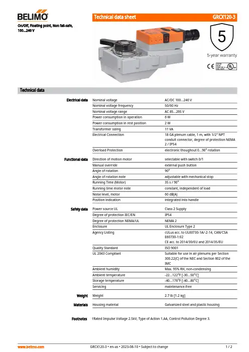
GRCX120-3FootnotesOn/Off, Floating point, Non fail-safe, 100...240 VTechnical dataElectrical dataNominal voltageAC/DC 100...240 V Nominal voltage frequency 50/60 Hz Nominal voltage rangeAC 85...265 V Power consumption in operation 6 W Power consumption in rest position 2 W Transformer sizing 11 VAElectrical Connection18 GA plenum cable, 1 m, with 1/2" NPTconduit connector, degree of protection NEMA 2 / IP54Overload Protectionelectronic thoughout 0...90° rotation Functional dataDirection of motion motor selectable with switch 0/1Manual override external push button Angle of rotation 90°Angle of rotation note adjustable with mechanical stop Running Time (Motor)35 s / 90°Running time motor note constant, independent of load Noise level, motor 60 dB(A)Position indicationintegrated into handle Safety dataPower source ULClass 2 Supply Degree of protection IEC/EN IP54Degree of protection NEMA/UL NEMA 2Enclosure UL Enclosure Type 2Agency ListingcULus acc. to UL60730-1A/-2-14, CAN/CSA E60730-1:02CE acc. to 2014/30/EU and 2014/35/EU Quality Standard ISO 9001UL 2043 CompliantSuitable for use in air plenums per Section 300.22(C) of the NEC and Section 602 of the IMCAmbient humidity Max. 95% RH, non-condensing Ambient temperature -22...122°F [-30...50°C]Storage temperature -40...176°F [-40...80°C]Servicingmaintenance-free Weight Weight2.7 lb [1.2 kg]MaterialsHousing material Galvanized steel and plastic housing†Rated Impulse Voltage 2.5kV, Type of Action 1.AA, Control Pollution Degree 3.GRCX120-3 Electrical installationINSTALLATION NOTESActuators with appliance cables are numbered.Provide overload protection and disconnect as required.Actuators may be connected in parallel. Power consumption and input impedance must beobserved.Meets cULus requirements without the need of an electrical ground connection.Warning! Live electrical components!During installation, testing, servicing and troubleshooting of this product, it may be necessaryto work with live electrical components. Have a qualified licensed electrician or other individualwho has been properly trained in handling live electrical components perform these tasks.Failure to follow all electrical safety precautions when exposed to live electrical componentscould result in death or serious injury.Wiring diagramsOn/Off AC 100...240 V Floating Point AC 100...240 V。
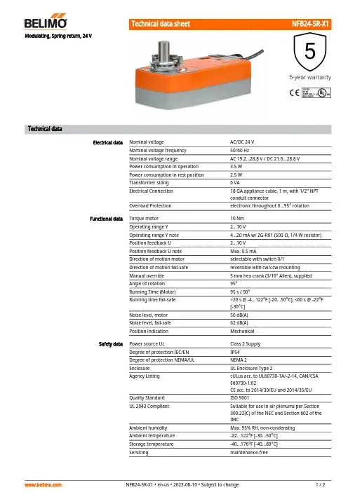
NFB24-SR-X1Modulating, Spring return, 24 VTechnical dataElectrical dataNominal voltageAC/DC 24 V Nominal voltage frequency 50/60 HzNominal voltage rangeAC 19.2...28.8 V / DC 21.6...28.8 V Power consumption in operation 3.5 W Power consumption in rest position 2.5 W Transformer sizing 6 VAElectrical Connection 18 GA appliance cable, 1 m, with 1/2" NPT conduit connectorOverload Protectionelectronic throughout 0...95° rotation Functional dataTorque motor 10 Nm Operating range Y 2...10 VOperating range Y note 4...20 mA w/ ZG-R01 (500 Ω, 1/4 W resistor)Position feedback U 2...10 V Position feedback U note Max. 0.5 mADirection of motion motor selectable with switch 0/1Direction of motion fail-safe reversible with cw/ccw mounting Manual override 5 mm hex crank (3/16" Allen), supplied Angle of rotation 95°Running Time (Motor)95 s / 90°Running time fail-safe <20 s @ -4...122°F [-20...50°C], <60 s @ -22°F [-30°C]Noise level, motor 50 dB(A)Noise level, fail-safe 62 dB(A)Position indicationMechanical Safety dataPower source ULClass 2 Supply Degree of protection IEC/EN IP54Degree of protection NEMA/UL NEMA 2Enclosure UL Enclosure Type 2Agency ListingcULus acc. to UL60730-1A/-2-14, CAN/CSA E60730-1:02CE acc. to 2014/30/EU and 2014/35/EU Quality Standard ISO 9001UL 2043 CompliantSuitable for use in air plenums per Section 300.22(C) of the NEC and Section 602 of the IMCAmbient humidity Max. 95% RH, non-condensing Ambient temperature -22...122°F [-30...50°C]Storage temperature -40...176°F [-40...80°C]Servicingmaintenance-freeNFB24-SR-X1FootnotesWeight Weight4.5 lb [2.0 kg]MaterialsHousing material Galvanized steel and plastic housing†Rated Impulse Voltage 800V, Type of Action 1.AA.B, Control Pollution Degree 3.Electrical installationINSTALLATION NOTESActuators with appliance cables are numbered.Provide overload protection and disconnect as required.Actuators may also be powered by DC 24 V.Only connect common to negative (-) leg of control circuits.A 500 Ω resistor (ZG-R01) converts the 4...20 mA control signal to 2...10 V.Actuators may be connected in parallel if not mechanically linked. Power consumption andinput impedance must be observed.Meets cULus requirements without the need of an electrical ground connection.Warning! Live electrical components!During installation, testing, servicing and troubleshooting of this product, it may be necessary to work with live electrical components. Have a qualified licensed electrician or other individual who has been properly trained in handling live electrical components perform these tasks. Failure to follow all electrical safety precautions when exposed to live electrical components could result in death or serious injury.Wiring diagrams2...10 V / 4...20 mA Control。
ZZYP型自力式压力调节阀一、产品概述ZZYP型自力式压力调节阀无需外加能源,利用被调介质自身能量为动力源,引入执行机构控制阀芯位置,改变两端的压差和流量,使阀前(或阀后)压力稳定。
具有动作灵敏,密封性好,压力设定点波动小等优点,广泛应用于气体、液体及蒸汽介质减压稳压或泄压稳压的自动控制。
二、性能参数1、调节机构主要性能参数公称通径DN(mm)20 25 32 40 50 65 80 100 125 150 200 250 300 额定流量系数Kv 7 11 20 30 48 75 120 190 300 480 760 1100 1750 额定行程(mm)8 10 14 20 25 40 50 60 70 公称压力(MPa) 1.6 4.0 6.4流量特性快开压力调节范围(KPa)15~50、40~80、60~100、80~140、120~180、160~220、200~260、240~300、280~350、330~400、380~450、430~500、480~560、540~620、600~700、680~800、780~900、880~1000、600~1500、1000~2500流量特性快开调节精度(%)±5工作温度℃液体≤120;气体≤80;带冷凝器和散热片≤350(适用于高温工况)适用介质执水、气体、蒸汽、低粘度介质允许泄漏量硬密封(L/h)单座≤10-4×阀额定容量(IV级);双座、套筒≤5×10-3阀额定容量(II级)软密封(ml/min)0.15 0.3 0.45 0.6 0.9 1.7 4 6.75 11.1 11.6减压比最大10 最小 1.252、主要零件材料材料名称/代号C(WCB)P(304)R(316)阀体WCB(ZG230-450)ZG1Cr18Ni9Ti(304)ZG1Cr18Ni12Mo2Ti(316)阀芯、阀座1Cr18Ni9Ti(304)1Cr18Ni9Ti(304)1Cr18Ni12Mo2Ti(316)阀杆1Cr18Ni9Ti 1Cr18Ni9Ti 1Cr18Ni12Mo2Ti膜片丁睛橡胶、乙丙橡胶、氯丁胶、耐油橡胶膜盖A3、A4钢涂四氟乙烯填料聚四氟乙烯、柔性石墨弹簧60Si2Mn导向套HPb59-13、外形尺寸公称通径(DN) 20 25 32 40 50 65 80 100 125 150 200 250 300L PN16、40 150 160 180 200 230 290 310 350 400 480 600 730 850 PN64 230 230 260 260 300 340 380 430 500 550 650 770 890 B 383 512 603 862 1023 1380 1800 2000 2200H15~140 475 520 540 710 780 840 880 915 940 1000 压力130~300455 500 520 690 760 800 870 880 900 950 调节280~500450 490 510 680 750 790 860 870 890 940 范围480~1000445 480 670 740 780 850 860 880 930KPa600~1500445 570 600 820 890 950 1000 1100 1200 1000~2500445 570 600 820 890 950 1000 1100 1200A15~140 φ580 φ308压力130~300φ230调280~φ176 φ194 φ280节500范围480~1000φ176 φ194 φ280KPa600~1500φ85 φ96 1000~2500φ85 φ96质量Kg 26 37 42 72 90 114 130 144 180 200 250 导压管接口螺纹M16×15。
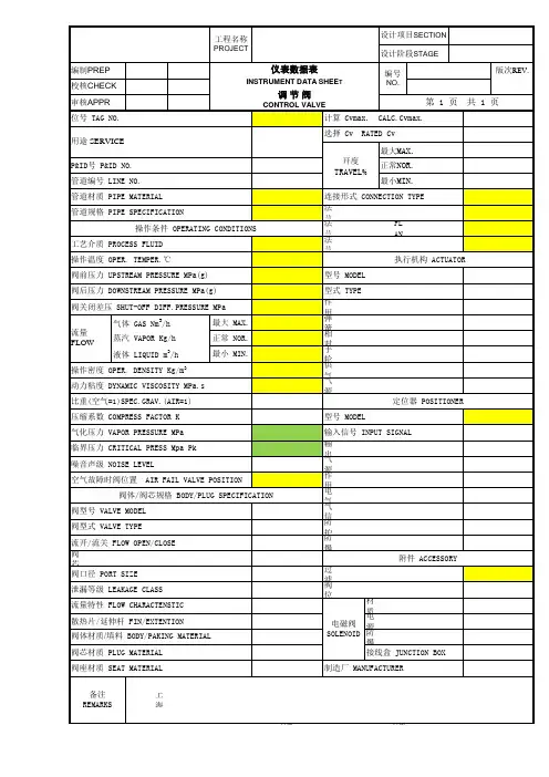
控制阀CONTROL VALVE
工程设计
位号 TAG NO.计算Cv最大/正常 CAL.Cv MAX./NOR.
选择 Cv RATED Cv
正常阀门开度 NOR.VALVE OPEN %P&ID号 P&ID NO.计算噪音声平 CAL.NOI.LEVEL dB(A)
管道编号 LINE NO.法兰标准及等级 FLANGE STD.& DEGREE 管道材质 PIPE MATERIAL 法兰尺寸及密封面 FLAN.SIZE & SEAL.
管道尺寸 PIPE SIZE
法兰材质 FLANGE MATERIAL
操作条件 OPERATING CONDITIONS
执行机构 ACTUATOR
工艺介质 PROCESS FLUID
型号 MODEL /尺寸 SIZE 最大/正常流量下温度 @MAX /NOR.FLOW TEMPER.℃型式 TYPE
最大流量下的入口压力 IN.PRESS.@MAX.F.kPa(g)
弹簧作用 SPRING ACTION
最大流量下的压降 PRESS.DROP @MAX.F.kPa
空气故障阀位置 AIR FAIL VALVE 正常流量下的入口压力 IN.PRESS.@NOR. F.kPa(g)
手轮 HAND WHEEL
定位器 POSITIONER
关闭压差 SHUT-OFF DIFFE.PRESSURE kPa-d 型号 MODEL
输入信号 INPUT SIGNAL
增加信号时阀位 INCREASE SIGNAL V.气源压力 AIR SUPPLY PRESS.操作密度 OPER. DENSITY kg/m 3
电气接口尺寸 ELEC.CONN.SIZE 动力粘度 DYNAMIC VISCOSITY cP 气源接口尺寸 AIR SUPP.CONN.SIZE 比重 SPECIFIC GRAVITY
防爆等级 EXPLOSION-PROOF CLASS
气体分子量 GAS MOLECULAR WEIGHT
附件 ACCESSORY
允许噪音声平 ALLOWED NOISE LEVEL dB(A)过滤器减压阀 REGULATOR 空气故障时阀位置 AIR FAIL VALVE POSITION
阀位开关 POSITION SWITH 阀体/阀内件规格 BODY/TRIM SPECIFICATION
电磁阀 SOLENOID 阀型号 VALVE MODEL 制造厂 MANUFACTURE 阀体型式 VALVE BODY TYPE 型号 MODEL NO.公称通径 NOMINAL DIAMETER (in)制导型式 GUIDING TYPE
阀座尺寸 SEAT SIZE/PORT SIZE (in) 下列数据在需要时填写。
FILL DATA WEHE NECESSARY.流量特性 FLOW CHARACTENSTIC 临界温度 CRITICAL TEMPERETURE ℃:上阀盖型式 BONNET TYPE 临界压力 CRITICAL PRESS kPa(a):泄漏等级 LEAKAGE CLASS 比热 SPECIFIC HEATRATIO K :阀体材质 BODY MATERIAL 膨胀系数 Y :
阀芯材质 PLUG MATERIAL 气体压缩系数 GAS COMPRESS FACTOR :阀座材质 SEAT MATERIAL
气化压力 VAPOR PRESSUREkPa(a):
备注 REMARKS
最小流量 MIN.FLOW
最大流量 MAX.FLOW kg/h 正常流量下的压降 PRESS.DROP @NOR. F.kPa 正常流量 NOR.FLOW kg/h 分项名称用途SERVICE 日期说明校核日期日期
设计修改
图号DWG. NO.SUBPROJECT 项目名称设计阶段
第张共张
SHEET OF
审核仪表数据表
合同号。