位移传感器教程文件
- 格式:ppt
- 大小:1.65 MB
- 文档页数:27
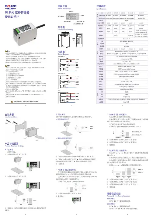
BL系列 位移传感器使用说明书Specifications规格参数Panel Description面板说明尺寸图Circuit Diagram电路图Installation Steps安装步骤Product Function Settings产品功能设置A 2点教导基本指导方法。
① 在无物体的状态下,按下“M”键。
① 在有检测物体P-1的状态下,按下“M”键(第1次)② 在有检测物体P-2的状态下,按下“M”键(第2次)③ 完成校准。
D 2点教导(窗口比较模式)执行2点教导,设定基准值范围的方法。
实施2点教导(窗口比较模式)的情况下,请事先在PRO模式的检测输出设定中设为[2点教导(窗口比较模式)]。
关于设定方法,请参考“⑫PRO模式操作说明”。
执行教导时,请使用距离有所不停的检测物体(P-1、P-2)E 3点教导(窗口比较模式)执行3点(P-1、P-2、P-3)教导,如下图所示,在第1次和第2次之间设定基准值1_SL,在第2次和第3次之间设定基准值2_SL,并设定基准值范围的方法。
执行3点教导(窗口比较模式)的情况下,请事先在菜单检测输出设定中设为[3点教导(窗口比较模式)]。
教导后,P-1、P-2、P-3将会按照由小到大的顺序自动排列。
② 在有物体的状态下,按下“M”键。
③ 完成校准。
(当两次教导差值较小时,显示回差太小,需要拉大差异再次教导)B 限定教导有微小物体和背景的情况下,如何使用该教导方法,则十分便利。
a. 背景为基准的情况下b. 检测物体为基准的情况下① 在有背景物体的状态或者在有检测物体的状态下,按下“M”键。
② 背景物体为基准的情况下,按下“▲”键后,在传感器中设定基准值。
检出物体为基准的情况下按下“▼”键后在检出物体中设定的值。
③ 完成校准。
本产品的光源采用可见半导体激光。
禁止激光束直接或从反射物体上间接反射进入眼睛。
若激光束进入眼睛将有可能造成失明危险。
本产品不设有防爆结构。
CWY50-5K位移传感器说明书CWY50-5K位移传感器说明书:位移传感器又称为线性传感器,在转换过程中有许多物理量(例如压力、流量、加速度等)常常需要先变换为位移,然后再将位移变换成电量。
因此位移传感器是一类重要的基本传感器。
位移传感器又称为线性传感器,在转换过程中有许多物理量(例如压力、流量、加速度等)常常需要先变换为位移,然后再将位移变换成电量。
因此位移传感器是一类重要的基本传感器。
在生产过程中,位移的测量一般分为测量实物尺寸和机械位移两种。
电感式位移传感器是一种属于金属感应的线性器件,接通电源后,在开关的感应面将产生一个交变磁场,当金属物体接近此感应面时,金属中则产生涡流而吸取了振荡器的能量,使振荡器输出幅度线性衰减,然后根据衰减量的变化来完成无接触检测物体的目的。
电容式位移传感器是一种非接触电容式原理的精密测量仪器,具有一般非接触式仪器所共有的无磨擦、无损磨和无惰性特点外,还具有信噪比大,灵敏度高,零漂小,频响宽,非线性小,精度稳定性好,抗电磁干扰能力强和使用操作方便等优点。
在国内研究所,高等院校、工厂和军工部门得到广泛应用,成为科研、教学和生产中一种不可缺少的测试仪器。
位移传感器在安装前,用户不要擅自拆卸、改装(包括撕去商标、在轴与壳体上进行加工、松动螵钉、转动固紧环位置等)。
位移传感器在安装过程中,应轻拿轻放,以免碰坏引出端;1、以位移传感器安装凸台定位,用螺钉、螺母或压板固紧在金属板上。
在安装传感器时,严禁对轴、壳体进行车、钻等加工,避免轴或壳体受到外界的冲击力和压力,轴的轴向和径向不允许受到冲击力和压力(静压力应小于300n)。
严禁松动传感器上的螺钉,转动固紧环位置。
2、出轴与其它机件联接时应注意轴心线要保持在一直线上(包括工作状态),如轴心线有偏差存在,建议使用万向接头或波纹管等转接件,以免传感器出轴弯曲变形,损坏其他器件,从而影响使用。
3、应防止水滴、蒸气、溶剂和腐蚀性气体对位移传感器的侵袭,防止金属屑或其他粉末进入传感器。
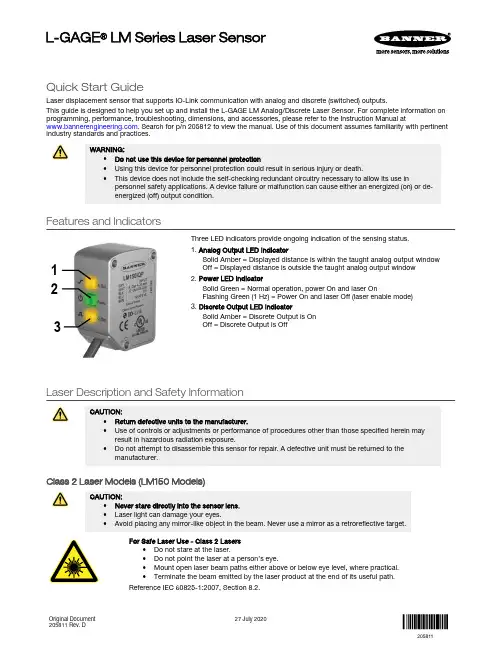
Quick Start GuideLaser displacement sensor that supports IO-Link communication with analog and discrete (switched) outputs.This guide is designed to help you set up and install the L-GAGE LM Analog/Discrete Laser Sensor. For complete information on programming, performance, troubleshooting, dimensions, and accessories, please refer to the Instruction Manual at . Search for p/n 205812 to view the manual. Use of this document assumes familiarity with pertinentindustry standards and practices.WARNING:•Do not use this device for personnel protection•Using this device for personnel protection could result in serious injury or death.•This device does not include the self-checking redundant circuitry necessary to allow its use inpersonnel safety applications. A device failure or malfunction can cause either an energized (on) or de-energized (off) output condition.Features and Indicators132Three LED indicators provide ongoing indication of the sensing status.1. Analog Output LED IndicatorSolid Amber = Displayed distance is within the taught analog output window Off = Displayed distance is outside the taught analog output window 2. Power LED IndicatorSolid Green = Normal operation, power On and laser OnFlashing Green (1 Hz) = Power On and laser Off (laser enable mode)3. Discrete Output LED IndicatorSolid Amber = Discrete Output is On Off = Discrete Output is OffLaser Description and Safety InformationCAUTION:•Return defective units to the manufacturer.•Use of controls or adjustments or performance of procedures other than those specified herein mayresult in hazardous radiation exposure.•Do not attempt to disassemble this sensor for repair. A defective unit must be returned to themanufacturer.Class 2 Laser Models (LM150 Models)CAUTION:•Never stare directly into the sensor lens.•Laser light can damage your eyes.•Avoid placing any mirror-like object in the beam. Never use a mirror as a retroreflective target.For Safe Laser Use - Class 2 Lasers•Do not stare at the laser.•Do not point the laser at a person’s eye.•Mount open laser beam paths either above or below eye level, where practical.•Terminate the beam emitted by the laser product at the end of its useful path.Reference IEC 60825-1:2007, Section 8.2.L-GAGE ® LM Series Laser SensorOriginal Document 205811 Rev. D27 July 2020205811Class 2 LasersClass 2 lasers are lasers that emit visible radiation in the wavelength range from 400 nm to 700 nm, where eye protection is normally afforded by aversion responses, including the blink reflex. This reaction may be expected to provide adequate protection under reasonably foreseeable conditions of operation, including the use of optical instruments for intrabeam viewing.LASER LIGHTDO NOT STARE INTO BEAMCLASS 2 LASER PRODUCTAcc to IEC 60825-1:2007.λ=640-670nm; P=0.45mWPW: 45-1,750msComplies with 21 CFR 1040.10 and 1040.11Except for deviations pursuant to laser noticeNo. 50, Dated June 24, 2007.Figure 1. FDA (CDRH) warning label (Class 2)Class 2 Laser Safety NotesLow-power lasers are, by definition, incapable of causing eye injury within the duration of ablink (aversion response) of 0.25 seconds. They also must emit only visible wavelengths(400 to 700 nm). Therefore, an ocular hazard may exist only if individuals overcome theirnatural aversion to bright light and stare directly into the laser beam.Class 1 Laser Models (LM80 Models)Class 1 lasers are lasers that are safe under reasonably foreseeable conditions ofoperation, including the use of optical instruments for intrabeam viewing.Figure 2. FDA (CDRH) warning label (Class 1) Laser wavelength: 655 nm Output: < 0.33 mW Pulse Duration: 45 µs to 1750 µsInstallation InstructionsSensor InstallationNote: Handle the sensor with care during installation and operation. Sensor windows soiled by fingerprints,dust, water, oil, etc. may create stray light that may degrade the peak performance of the sensor. Blow thewindow clear using filtered, compressed air, then clean as necessary using 70% isopropyl alcohol and cottonswabs or water and a soft cloth.Install the Safety LabelThe safety label must be installed on or near the LM sensors.Note:Position the label on the cable or near the sensor in a location that has minimal chemical exposure.Figure 3. Typical installation; other mounting options are possible.1.Remove the protective cover from the adhesive on the label.2.Wrap the label around the LM cable, as shown.3.Press the two halves of the label together. - Tel: + 1 888 373 6767P/N 205811 Rev. DSensor OrientationCorrect sensor-to-object orientation is important to ensure proper sensing. See the following figures for examples of correct and incorrect sensor-to-object orientation as certain placements may pose problems for sensing distances.Figure 4. Orientation by a wall IncorrectCorrect Figure 5. Orientation in an openingIncorrectCorrectFigure 6. Orientation for a turning objectIncorrectCorrectFigure 7. Orientation for a height difference IncorrectCorrectFigure 8. Orientation for a color or luster difference Figure 9. Orientation for a highly reflective targetApplying tilt to sensor may improve performance on reflective targets. The direction and magnitude of the tilt depends on the application, but a 15° tilt is often sufficient.Mount the Device1.If a bracket is needed, mount the device onto the bracket.2.Mount the device (or the device and the bracket) to the machine or equipment at the desired location. Do not tighten themounting screws at this time.3.Check the device alignment.4.Tighten the mounting screws to secure the device (or the device and the bracket) in the aligned position.Wiring Diagrams+–* Push-Pull output. User-configurable PNP/NPN setting.*Key 1 = Brown 2 = White 3 = Blue 4 = Black 5 = Gray+–* Push-Pull output. User-configurable PNP/NPN setting.*The bare shield wire is connected internally to the sensor housing and should be connected as follows:•If the sensor housing is mounted so that it is in continuity with both the machine frame and earth ground, connect the barewire (also) to earth ground.•If the sensor housing is mounted so that it is insulated from the machine frame and you are experiencing noise, connectingthe bare wire to -V dc (together with the blue wire), may help.•If the sensor is mounted so that it is in continuity with the machine frame, but not with earth ground, do not connect thebare wire (e.g. cut off the bare wire).P/N 205811 Rev. D - Tel: + 1 888 373 67673Configuration InstructionsSensor ProgrammingProgram the sensor using the buttons on the RSD1 remote sensor display accessory, via IO-Link, or the remote input (limited programming options).If you are using the RSD1 for programming, from Run mode, use the buttons to access the Quick Menu and the Sensor Menu. See the instruction manual (p/n 205812) for more information on the options available from each menu. For TEACH options, follow the TEACH instructions in the instruction manual.In addition to programming the sensor, use the remote input to disable the buttons for security, preventing unauthorized or accidental programming changes. See the instruction manual for more information.from Run Mode> 4 sec.Access Sensor Menu Access RSD1 MenuFigure 10. Accessing the MenusRemote Display Buttons and the LMUse the RSD1 buttons Down , Up , Enter , and Escape to view or change RSD1 settings and information and to program a connected sensor.Down and Up Buttons Press Down and Up to:•Access the Quick Menu from Run mode •Navigate the menu systems •Change programming settings•Change individual digit values in distance based settings When navigating the menu systems, the menu items loop.Press Down and Up to change setting values. Press and hold the buttons to cycle through numeric values. After changing a setting value, the value slowly flashes until the change is saved using the Enter button.Enter Button Press Enter to:•Access the Sensor Menu from Run mode •Access the submenus•Move right one digit in distance based settings •Save changesIn the RSD1 Menu, a check mark in the lower right corner of the display indicates that pressing Enter accesses a submenu.Press Enter to save changes. New values flash rapidly, and the sensor returns to the parent menu. - Tel: + 1 888 373 6767P/N 205811 Rev. DEscape ButtonPress and hold Escape for 4 seconds to:•Access the RSD1 Menu while in Run modePress Escape to:•Leave the current menu and return to the parent menuImportant: Pressing Escape discards any unsaved programming changes.In the RSD1 Menu, a return arrow in the upper left corner of the display indicates that pressing Escape returns to the parent menu.Press and hold Escape for 2 seconds to return to Run mode from the RSD1 Menu.Quick MenuThe sensor includes a Quick Menu with easy access to view and change the analog and discrete output switch points.Access the Quick Menu by pressing Down or Up from Run mode. When in the Quick Menu, the current distance measurement displays on the first line and the menu name and the analog value alternate on the second line of the display. Press Enter to access the switch points.Press Down or Up to change the switch point to the desired value.Press Enter to save the new value and return to the Quick Menu.* In Setpoint mode, SPt1 Pt is replaced by SPt and SPt2 Pt is not available.In Dual mode, SPt1 is replaced by DualSPt and SPt2 Pt is not available.Sensor Menu (MENU)Access the Sensor Menu by pressing Enter from Run mode. The Sensor Menu is also accessible from the Quick Menu: navigate to MENU and press Enter. The Sensor Menu includes several submenus that provide access to view and change sensor settings and to view sensor information.P/N 205811 Rev. D - Tel: + 1 888 373 67675SensorMenu Full MapFrom Run mode, press Enter to enter the top-level menu system (A_OUT, D_OUT, INPUT, MEASURE, etc).Top Menu* Factory default setting - Tel: + 1 888 373 6767P/N 205811 Rev. DSpecificationsSupply Voltage (Vcc)10 V dc to 30 V dcUse only with a suitable Class 2 power supply (North America) Power and Current Consumption, exclusive of loadNormal Run Mode: 1.5 W, Current consumption < 62 mA at 24 V dc Supply Protection CircuitryProtected against reverse polarity and transient overvoltages Ambient Light Immunity10,000 luxConstructionHousing: stainless steelWindow: acrylic Sensing BeamVisible red, 655 nmSensing RangeLM80: 40 to 80 mmLM150: 50 mm to 150 mmDelay at Power Up2.1 sMeasurement/Output Rate0.25 ms to 4 ms; user selectable from the Speed menu Output ConfigurationAnalog output: 4 to 20 mA (LM...I Models) or 0 to 10 V DC (LM...U Models)Discrete output: Push/Pull, IO-LinkOutput RatingsDiscrete Output: 50 mA maximum (protected against continuous overload and short circuit)Output saturation voltage (PNP): < 3 V at 50 mAOutput saturation voltage (NPN): < 2.5 V at 50 mAAnalog current output (LM...I Models): 500 Ω maximumAnalog voltage output (LM...U Models): 1000 Ω minimum Maximum Torque1.5 N·mRemote InputAllowable Input Voltage Range: 0 to VccActive Low (internal weak pullup—sinking current):High State: > 3.6 VLow State: < 2.4 VActive High (internal weak pulldown—sourcing current): High State: > Vcc - 2.9 VLow State: < Vcc - 4.6 VMinimum Window Size, Analog and DiscreteLM80:Analog: 1 mmDiscrete: 0.024 mmLM150:Analog: 1 mmDiscrete: 0.1 mm Analog ResolutionLM80: 0.002 mmLM150: 0.004 mmRepeatabilityLM80: ± 0.001 mm1LM150: ± 0.002 mm 2Analog and IO-Link LinearityLM80:40–70 mm: ± 0.02 mm70–80 mm: ± 0.03 mmLM150:50–120 mm: ± 0.06 mm120–150 mm: ± 0.07 mmIO-Link Accuracy3LM80: ± 0.175 mmLM150: ± 0.2 mmTemperature Effect, TypicalLM80: ± 0.006 mm/°CLM150: ± 0.008 mm/°CResponse TimeTotal response speed varies from 0.5 ms to 2048 ms, depending on base measurement rate and averaging settings.See Instruction Manual for more information.Minimum Object SeparationLM80:Uniform targets (6% to 90% reflectivity) 40–70 mm: 0.04 mmUniform targets (6% to 90% reflectivity) 70–80 mm: 0.06 mmNon-uniform targets (6% to 90% reflectivity): 0.4 mmLM150:Uniform targets (6% to 90% reflectivity) 50–120 mm: 0.120 mmUniform targets (6% to 90% reflectivity) 120–150 mm: 0.140 mm Non-uniform targets (6% to 90% reflectivity): 0.8 mm Environmental RatingIEC IP67Operating Conditions–10 °C to +55 °C (+14 °F to +131 °F)90% at +55 °C maximum relative humidity (non-condensing) Storage Temperature–35 °C to 60 °C (–31°F to 140 °F)Boresighting± 0.70 mm at 40 mm± 0.87 mm at 50 mm± 1.40 mm at 80 mm± 2.62 mm at 150 mmVibration/Mechanical ShockMeets IEC 60947-5-2 (10 to 60 Hz max., double amplitude 0.06 in, max acceleration 10G. 30G 11 ms duration, half sine wave) Application NoteFor optimum performance, allow 10 minutes for the sensor to warm upCertificationsUL Type 1with 128× averaging. With 1× averaging, repeatability of ± 0.004 mm from 40 to 80 mm.with 128× averaging. With 1× averaging, repeatability of ± 0.005 mm from 50 to 120 mm and ± 0.010 mm from 120 to 150 mm.3The accuracy specification refers to the possible absolute offset when installing a sensor without taking any reference measurement.Linearity is the more relevant specification for most applications.P/N 205811 Rev. D - Tel: + 1 888 373 67677Typical Beam Spot Size4Required Overcurrent ProtectionWARNING: Electrical connections mustbe made by qualified personnel inaccordance with local and nationalelectrical codes and regulations.Overcurrent protection is required to be provided by endproduct application per the supplied table.Overcurrent protection may be provided with external fusing orvia Current Limiting, Class 2 Power Supply.Supply wiring leads < 24 AWG shall not be spliced.For additional product support, go to.FCC Part 15 and CAN ICES-3 (B)/NMB-3(B)This device complies with part 15 of the FCC Rules and CAN ICES-3 (B)/NMB-3(B). Operation is subject to the following two conditions:1.This device may not cause harmful interference, and2.This device must accept any interference received, including interference that may cause undesired operation.This equipment has been tested and found to comply with the limits for a Class B digital device, pursuant to part 15 of the FCC Rules and CAN ICES-3 (B)/NMB-3(B). These limits are designed to provide reasonable protection against harmful interference in a residential installation. This equipment generates, uses and can radiate radio frequency energy and, if not installed and used in accordance with the instructions, may cause harmful interference to radio communications. However, there is no guarantee that interference will not occur in a particular installation. If this equipment does cause harmful interference to radio or television reception, which can be determined by turning the equipment off and on, the user is encouraged to try to correct the interference by one or more of the following measures:•Reorient or relocate the receiving antenna.•Increase the separation between the equipment and receiver.•Connect the equipment into an outlet on a circuit different from that to which the receiver is connected.•Consult the manufacturer.Banner Engineering Corp. Limited WarrantyBanner Engineering Corp. warrants its products to be free from defects in material and workmanship for one year following the date of shipment. Banner Engineering Corp. will repair or replace, free of charge, any product of its manufacture which, at the time it is returned to the factory, is found to have been defective during the warranty period. This warranty does not cover damage or liability for misuse, abuse, or the improper application or installation of the Banner product.THIS LIMITED WARRANTY IS EXCLUSIVE AND IN LIEU OF ALL OTHER WARRANTIES WHETHER EXPRESS OR IMPLIED (INCLUDING, WITHOUT LIMITATION, ANY WARRANTY OF MERCHANTABILITY OR FITNESS FOR A PARTICULAR PURPOSE), AND WHETHER ARISING UNDER COURSE OF PERFORMANCE, COURSE OF DEALING OR TRADE USAGE. This Warranty is exclusive and limited to repair or, at the discretion of Banner Engineering Corp., replacement. IN NO EVENT SHALL BANNER ENGINEERING CORP. BE LIABLE TO BUYER OR ANY OTHER PERSON OR ENTITY FOR ANY EXTRA COSTS, EXPENSES, LOSSES, LOSS OF PROFITS, OR ANY INCIDENTAL, CONSEQUENTIAL OR SPECIAL DAMAGES RESULTING FROM ANY PRODUCT DEFECT OR FROM THE USE OR INABILITY TO USE THE PRODUCT, WHETHER ARISING IN CONTRACT OR WARRANTY, STATUTE, TORT, STRICT LIABILITY, NEGLIGENCE, OR OTHERWISE.Banner Engineering Corp. reserves the right to change, modify or improve the design of the product without assuming any obligations or liabilities relating to any product previously manufactured by Banner Engineering Corp. Any misuse, abuse, or improper application or installation of this product or use of the product for personal protection applications when the product is identified as not intended for such purposes will void the product warranty. Any modifications to this product without prior express approval by Banner Engineering Corp will void the product warranties. All specifications published in this document are subject to change; Banner reserves the right to modify product specifications or update documentation at any time. Specifications and product information in English supersede that which is provided in any other language. For the most recent version of any documentation, refer to: .For patent information, see /patents.© Banner Engineering Corp. All rights reserved。
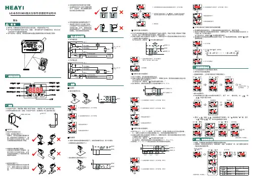
使用说明书CMOS激光位移传感器LC-S 系列●NPN输出型~24V DC10%●PNP 输出型~24V DC 10%点教导●。
法方导教的本基背景物体检测物体1. 在有背景物体的状态下,按下SET 键。
2. 在有检测物体的状态下,按下SET 键。
可稳定检测的情况下无法稳定检测的情况下●。
利便分十则,法方导教该用使如,下况情的体物景背和体物小微有<背景物体为基准的情况下><检出物体为基准的情况下>1.在有背景物体的状态或者在有检测物体的状态下,按下SET 键。
2.3. 教导结束。
●用使请,时品产本装安M3螺丝(请另行准备)。
请使用05N m .∙的拧紧力矩。
●用使请也,时品产本装安)售另(架支装安器感传用使05N m .∙的拧紧力矩。
安装孔尺寸●相对于移动体的方向<材质、有色差的情况下>• 材的物象对量测的动移,时量测质、颜色极端不同的情况下,按照下图所示方向进行安装,从而可将测量误差控制在最小限度。
<对旋转的对象物进行测量>• 按,时量测行进物象对的转旋对照下图所示方向进行安装,从而可抑制对象物的上下振动和位置偏移等的影响。
<有段差的情况下>• 情的差段在存物象对量测的动移况下,按照下图所示方法进行安装,从而可抑制段差边缘的影响。
●在狭隘场所和凹陷部分进行测量点教导(窗口比较模式)●值限下和值限上置设行实而,导教点1施实不时离距的间之面准基体物测检与对针的方法。
在上下限范围内进行判别时,使用该功能。
●实施1点教导(窗口比较模式)的情况下,请事先在PR O 模式的检测输出设定中设为[1点教导(窗口比较模式)]。
关于设定方法,请参考“ ”9PRO 模式操作说明。
2SL_1SL_1.在有检测物体的情况下,按下SET 键次。
2(第1次:SET 模式、第次:教导)22. 教导结束。
点教导(窗口比较模式)●执行2点教导,设定基准值范围的方法。
● 实施2点教导(窗口比较模式)的情况下,请事先在PRO 模式的检测输出设定中设为[2点教导(窗口比较模式)]。

AMETEK位移传感器技术操作使用资料AMETEK位移传感器技术操作使用资料共享AMETEK料位开关自动识别功能,并采纳2″安装嘴,可由容器内搅拌器或障碍物产生的干扰回波。
5098XTrueLevel系列智能型连续物位计 TrueLevel系列为智能型两线制连续物位掌控仪表,其由两部分构成,其中一部分用来检测物料的电特性的变化,另一部分检测物位的变化,其测量不受介质的介电常数,密度,温度和变化的影响,适用于混合罐,缓冲罐等测量场合。
输出为4~20mA,带Hart通讯协议,可整体或?/t 5091XUniversalLite系列通用智能型连续物 UniversalLite为通用型智能型两线制连续物位掌控仪表,输出为4~20mA带Hart通讯协议仪表可选就地显示装置,可选键盘调试功能。
仪表由电路单元和杆式(或缆式)传感元件构成,传感器可选多种材质,可整体或分体安装。
RS 系列电源同时具备供电和储能本领,即支持双向电流流动。
RS 放大器可颠倒交流输入的相位关系程控储能(SNK)运行模式。
RS 系列产品可*通过菜单驱动的前置面板掌控器进行操作。
背光 LCD 显示屏为您显示菜单、设置数据和回读测量数据。
产品还供给普遍用于 ATE 编程环境的 IEEE488、RS232C、USB 和 LAN 远程掌控接口和仪器驱动程序。
如此就能将 RS 系列产品轻松集成到自动测试系统中。
对于高级测试应用,程控掌控器版本能供给完整的任意波形生成功能、时域和频域测量功能以及电压和电流波形捕获功能。
盲区天线延长长度+天线长度+0.1m/4″l输出40~20mAHART或3.8—20.5mA,依据NAMURNE43输出信号0.05%(能量损耗率20mA;20°C/68°F)辨别率2Μa温度漂移一般为50ppm/k错误信号高:22mA;低3.6mA,依据NAMURNE43负载350Ωl测量精度—标准条件依据IEC770温度+20°C5°C/+68°F9°F压力值1013mbar20mbar/14.69psig0.29psig相对湿度60%15%辨别率1m m/0.04″精度3mm/0.12″发射角DN40/ANSI11/2″20°DN50/ANSI2″15°DN80/ANSI3″10°l应用条件环境温度—40~+80°C—40~+175°F;EexI:—40~+60°C/—40~+140°F存储温度—40~+85°C—40~+185°F法兰温度—40~+150°C—40~+300°F温度剧变承受力100°C/minl过程条件操作压力—1~40bar/—14.5~580psig;与过程连接和温度有光介电常数≥1.5耐振动IEC6826andprEN50178(10~57Hz:0.075mm/57~150Hz:1g)防护等级IP66/67对应于NEMA6—6Xl机械数据外壳铝湿料部分不锈钢(1.4404/316L);哈氏合金C—22(2.4602)连接部分不锈钢(1.4404/316L);哈氏合金C—22(2.4602)垫圈Viton(—40~+150°C—40~+300°F);Kalrez6753(—20~+150°C—5~+300°F)l过程连接螺纹G11/2″;NPT11/2″法兰DN40~DN150(PN/40PN16);11/2″~8″(150lb/300lb);10K(40~100)l电气连接-两线制电源终端输出非Ex/EExI24VDC(14~30VDC)EExd24VDC(20~36VDC)电气接口M20X1.5;1/2″NPT;G1/2″接线端子0.5~1.5mm?l人机界面显示9行,160160像素,8级灰阶,4按钮键盘操作语言英语,德语,法语,意大利语,西班牙语,葡萄牙语,日语,中文,俄语l认证防益出保护WHGATEXATEXllGDEExiallCT3T6ATEXll1/2GDEExd[ia]llCT3T6FMISclassIDiv.1Gr.AG;IPclassIDiv.1Gr.AG;CSAISclassIDiv.1Gr.AG;AMETEK位移传感器技术操作使用资料共享。
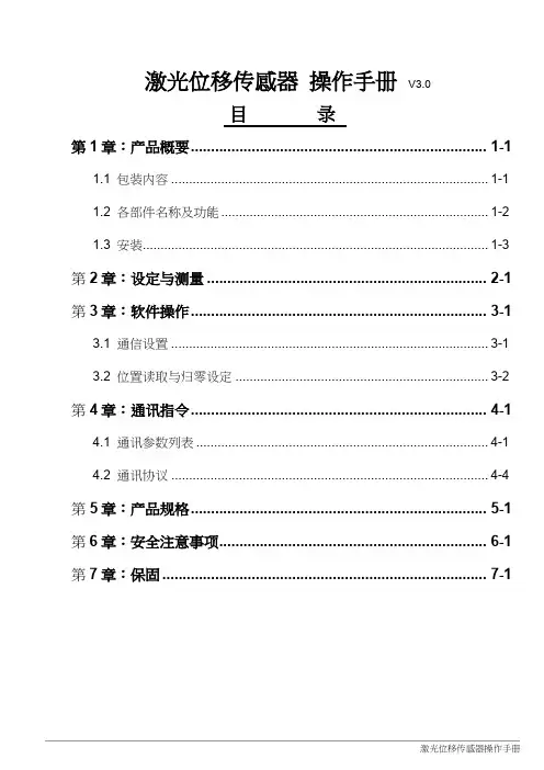
激光位移传感器操作手册V3.0目录第1章:产品概要......................................................................... 1-11.1 包装内容 ......................................................................................... 1-11.2 各部件名称及功能........................................................................... 1-21.3 安装................................................................................................. 1-3 第2章:设定与测量 ..................................................................... 2-1 第3章:软件操作......................................................................... 3-13.1 通信设置 ......................................................................................... 3-13.2 位置读取与归零设定 ....................................................................... 3-2 第4章:通讯指令......................................................................... 4-14.1 通讯参数列表 .................................................................................. 4-14.2 通讯协议 ......................................................................................... 4-4 第5章:产品规格......................................................................... 5-1 第6章:安全注意事项.................................................................. 6-1 第7章:保固 ................................................................................ 7-1版本更新历程激光位移计操作手册V3.0版本更新历程版本更新日期V1.0 第一版发行2018/09/03V2.0 新增「反应速度设定」与「中值滤波器设定」功能说明与通讯地址设定方式。
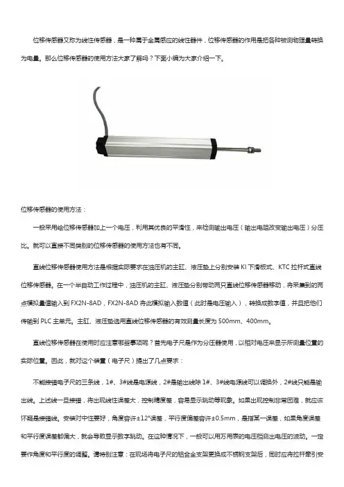
位移传感器又称为线性传感器,是一种属于金属感应的线性器件,位移传感器的作用是把各种被测物理量转换为电量。
那么位移传感器的使用方法大家了解吗?下面小编为大家介绍一下。
位移传感器的使用方法:一般采用给位移传感器加上一个电压,利用其优良的平滑性,来检测输出电压(输出电阻改变输出电压)分压比。
就可以直接不同类别的位移传感器的使用方法也有不同。
直线位移传感器使用方法是根据实际要求在油压机的主缸、液压垫上分别安装Kl下滑板式、KTC拉杆式直线位移传感器。
在一个半自动工作过程中,油压机的主缸、液压垫分别带动两只直线位移传感器移动,将采集到的两点模拟量值输入到FX2N-8AD,FX2N-8AD将此模拟输入数值(此时是电压输入),转换成数字值,并且把他们传输到PLC主单元。
主缸、液压垫选用直线位移传感器的有效测量长度为500mm、400mm。
直线位移传感器在使用时应注意哪些事项呢?首先电子尺是作为分压器使用,以相对电压来显示所测量位置的实际位置。
因此,就对这个装置(电子尺)提出了几点要求:不能接错电子尺的三条线,1#、3#线是电源线,2#是输出线除1#、3#线电源线可以调换外,2#线只能是输出线。
上述线一旦接错,将出现线性误差大,控制精度差,容易显示跳动等现象。
如果出现控制非常困难,就应该怀疑是接错线。
安装对中性要好,角度容许±12°误差,平行度偏差容许±0.5mm,是指某一误差,如果角度误差和平行度误差都偏大,就会导致显示数字跳动。
在这种情况下,一般可以用万用表的电压档测出电压的波动。
一定要作角度和平行度的调整。
请特别注意:在现场将电子尺的铝合金支架更换成不锈钢支架后,同时应将拉杆牵引安装位升高2Mm。
否则,接地问题解决了,又形成了不对中的问题,必须同时解决。
供电电源要有足够的容量,如果电源容量太小,容易发生如下情况:合模运动会导致射胶电子尺显示跳动,或熔胶运动会导致合模电子尺的显示波动。

线性位移传感器的使用教程线性位移传感器是一种常见的测量设备,用于测量物体在直线方向上的位移或位移速度。
它被广泛应用于工业自动化、机械工程、航空航天等领域。
本文将详细介绍线性位移传感器的基本原理、使用方法以及常见问题解答,帮助读者更好地理解和应用这一技术。
一、线性位移传感器的基本原理线性位移传感器基于变电容、光电、电磁感应等原理,通过测量电、光、磁信号的变化来确定位移的大小。
其中最常见的是电阻式线性位移传感器,它利用了电阻值与位移之间的一一对应关系。
电阻式线性位移传感器由感应器、可变电阻和信号处理器组成。
感应器将位移转化为电阻的变化,可变电阻根据电阻变化调节电压或电流信号,信号处理器将调整后的信号转化为数字信号或模拟信号输出。
二、线性位移传感器的使用方法1. 安装传感器:将线性位移传感器固定在测量物体上。
注意确保传感器与被测物体之间没有杂物或摩擦,以免影响测量精度。
接线时要注意保持电缆整洁,避免过长或过短。
2. 参数设置:根据具体需求,设置传感器的工作参数,如量程范围、输出方式、响应时间等。
大多数传感器都提供了参数设置的接口或按钮,可以通过用户手册进行操作。
3. 信号接收:将传感器的信号接收模块与计算机或监控设备相连。
一般情况下,传感器的输出信号是模拟信号,需要通过模数转换器将其转换为数字信号,以便进一步处理和分析。
4. 数据分析:将传感器输出的数据导入计算机软件或数据采集系统,进行数据分析和处理。
根据需求,可以使用统计软件、自定义算法等方法进行数据处理,得出位移值、位移速度等相关结果。
三、线性位移传感器的常见问题解答1. 为什么需要校准传感器?由于传感器在使用过程中可能会受到外界干扰或存在一定的漂移现象,因此需要对传感器进行校准。
校准可以修正传感器的误差,提高测量的准确性和可靠性。
2. 如何进行传感器的校准?传感器的校准需要使用标准样品或校准仪器。
通过将标准样品与传感器进行比对,确定修正系数,使得传感器输出的信号与实际位移相吻合。
● R e a d t h i s I n s t r u c t i o n M a n u al before use for the safe and correct operation.● Keep this Instruction Manual for the future reference and refer to itwhenever necessary.Table of ContentspageSAFETY PRECAUTIONS (3)Meanings of Safety Symbols ...............................3Mandatory Requirements.....................................4Precautions for Installation ..................................5Operating Precautions ..........................................5Cautions for Laser Product . (6)Speci fi cations .....................................8BASIC INFORMATION BEFORE USE . (10)Parts Identi fi cations of Sensor Head ..................10Package Descriptions .........................................10Option . (11)Sensor Head Installation (12)Installing Direction ............................................12Distance indicator ..............................................14Sensor head Installation .....................................15Connecting Connectors for Sensor Head .. (16)APPENDIX (17)Sensor Head Instruction ManualLaser Type(CD5-L_25,CD5-_30,CD5-_85,CD5-W350,CD5-W500,CD5-W2000)93, Chudoji Awata, Shimogyo-ku, Kyoto, 600-8815 JapanTel : +81-75-325-2920 Fax : +81-75-325-2921Manufactured and sold by :FOREWORDThank you for purchasing the Displacement Sensor CD5 Series. We hope you are fully satisfied with this product and enjoy its performance. To ensure your satisfaction, please follow the instructions below.● Carefully read this instruction manual and keep it for future reference.● If you have any question about the instructions here or a request for replacingthe lost instruction manual, contact the sales office or store where you purchased this product.●The contents in this instruction manual are protected by copyright and allrights are reserved by OPTEX FA CO., LTD. The descriptions and information included in this manual shall not be copied nor reproduced to any other form.This products may be listed as articles to be regulated for export such asstrategic materials by the Foreign Exchange and Foreign Trade Control Act.Therefore, if you intend to export these, be sure to follow the necessaryprocedures, such as application for an export permit from the Government.WarrantyWhereas all of our products are tested in accordance with the strict internal standard, a faulty unit may unexpectedly be distributed. If this is the case with your product, identify its status and contact the sales office or store where you purchased it.● The warranty period shall be one(1) year after its delivery to the customer.● If the failure results from a manufacturer' s fault, the manufacturer will replacethe product (by sending a substitute) without charge except the following cases :1. Failure due to any abuse or misuse2. Failure due to a cause other than the product3. Failure due to unapproved modifi cation or repair4. Failure due to acts of GodThis warranty is limited to the delivered product only.This warranty shall not cover the secondary damage caused by the faulty product.2▼Displacement sensorSAFETY PRECAUTIONSCarefully read and understand the safety precautions before operation.They provide the important information to protect your health and property. Strictly follow this instruction manual, and do not apply any other installing/operating procedure which is not described in this manual.Meanings of Safety SymbolsCD5 Sensor Head ▼3Mandatory Requirements4▼Displacement sensorPrecautions for InstallationOperating Precautions・Do not use the product just after turning on. A warm-up operation over 30 minutes is required before use.・The sensor performance may depend on the individual units.・Wipe off dirt on the cover (glass) of the emitting/receiving parts using a soft cloth etc., at every operation since it may cause incorrect detection.CD5 Sensor Head ▼5Cautions for Laser ProductThis sensor emits visible laser beam compliant with JIS C6802/IEC/FDA, laser safety standard Class 1, 2 (Ⅱ) or 3R (Ⅲa).The warning and description labels are stuck on the side of the product.Laser type of this productType Red Laser DiodeWavelength650 nm / 658 nmOutput390 μW / 1 mW / 5 mWThis sensor is subject to the FDA laser standard when exported to U.S.A. The report of this sensor has been submitted to Center for Devices and Radiological Health (CDRH).6▼Displacement sensorLabel of each model・CD5-L25 / CD5-LW25・CD5-30 / CD5-W30・CD5-85 / CD5-W85・CD5-W350・CD5-W500・CD5-W2000CD5 Sensor Head ▼7Specifications<MeasurementUnless otherwise designated, measurement condition is as follows. Using special controller/ operating (depending on models)/ 256 times in average/ center/ standard testing object (specular refl ection: eva *1 : Defi ned with center strength 1/e(13.5%) at the center. There may be leak light other than the specifi ed spo *2 : 4096 times in average. Other conditions are same as the above condition.*3 : Default setting of sampling period is as follows.CD5-□□25 □85 :100μsCD5-W350 W2000 :800μs*4 : The typical value in the above condition.8▼Displacement sensorg temperature, 23 ℃ (ordinary temperature)/ supply voltage, 24 V DC/ sampling period, 100 μs or 800 μs porated aluminum mirror, diffuse refl ection: white ceramic)/ digital measured value.t size. The sensor may be affected when there is a highly refl ective object close to the detection area.CD5 Sensor Head ▼910▼Displacement sensorBASIC INFORMATION BEFORE USEParts Identi fications of Sensor HeadConnector to ControllerDistance M4screw screw holeCable( 7.10.5m)Package Descriptions●Sensor Head Main Unit ●Screw(3 pcs.)●Instruction Manual (This document)●Laser Label to stick on the deviceOption●E xtension cable between sensor head andcontrollerLength (L)Cable type 2m DSL-1212-G02M 5mDSL-1212-G05M●E xtension cable for sensor head(For independent use of sensor head)Length(L)Cable type 5mD O L-1212-G05MIt is possible to use the CD5 sensor head without the special controller by connecting the CD5 sensor head directly to the device. The fi gure below shows how to connect the cable.Contact OPTEX FA for communicative speci fications (RS422) or wiring.Sensor Head InstallationInstalling DirectionFor a stable and accurate measurement, install the sensor head in the following direction to the target object.● Object with steps● Object of two or more materials or colors● Rotating object● To measure hole or concave● To fix the sensor head on the wall The detection surface (the side of the emitting/receiving parts) should be parallelto the target object. Adjust the spot to conform to the detection point. Ensure that the distance indicator turns orange when the detection point (the center of displacement) passes the spot point.Distance indicatorA distance indicator lights as follows.Outside the detection rangethe rangeSensor head InstallationConnecting Connectors for Sensor HeadM emo・ To remove connector from the controller, turn the lock in counterclockwise direction.APPENDIX Dimensional Drawing CD5-L25 / CD5-LW25CD5-30 / CD5-W30CD5-85 / CD5-W85CD5-W350CD5-W500CD5-W2000Umit:mm (Center)。
位移传感器教案教案标题:位移传感器教案教案概述:本教案旨在帮助学生理解位移传感器的原理和应用,并通过实践操作加深他们对位移传感器的认识。
通过本教案,学生将学会使用位移传感器进行测量和数据采集,并能够分析和解释测量结果。
本教案适用于中学物理或工程类课程。
教学目标:1. 理解位移传感器的工作原理和应用领域。
2. 学会使用位移传感器进行测量和数据采集。
3. 能够分析和解释位移传感器的测量结果。
4. 培养学生的实验设计和数据处理能力。
教学准备:1. 位移传感器(如线性位移传感器或旋转位移传感器)。
2. 测量设备(如数据采集器、计算机等)。
3. 实验器材和材料(如物体、直线轨道等)。
4. 实验指导书和教学资源。
教学过程:1. 引入(5分钟):- 引导学生思考并回答以下问题:你知道什么是位移传感器吗?它有什么作用? - 通过展示位移传感器的实物或图片,激发学生对位移传感器的兴趣。
2. 理论讲解(10分钟):- 介绍位移传感器的工作原理和分类。
- 解释位移传感器在实际应用中的作用和意义。
- 提供实际应用案例,让学生理解位移传感器的实际应用价值。
3. 实验操作(30分钟):- 分发实验指导书和实验器材,向学生解释实验步骤和安全注意事项。
- 学生按照实验指导书的要求,使用位移传感器进行测量和数据采集。
- 鼓励学生在实验过程中积极思考和交流,并记录实验数据。
4. 数据分析与讨论(15分钟):- 引导学生分析实验数据,观察位移传感器的测量结果。
- 讨论位移传感器的精度、灵敏度和测量范围等特性。
- 引导学生思考位移传感器在实际应用中可能遇到的问题,并提出改进方案。
5. 总结与拓展(10分钟):- 总结本节课的重点内容和学习收获。
- 提出拓展问题,鼓励学生进一步思考位移传感器的发展趋势和应用前景。
- 分发相关阅读材料或视频资源,供学生自主学习和拓展知识。
评估方法:1. 实验报告:要求学生撰写实验报告,包括实验目的、步骤、数据分析和结论等内容。