1994-24(6)Optimization of ultra-high-performance concrete by the use of a packing model
- 格式:pdf
- 大小:730.34 KB
- 文档页数:13
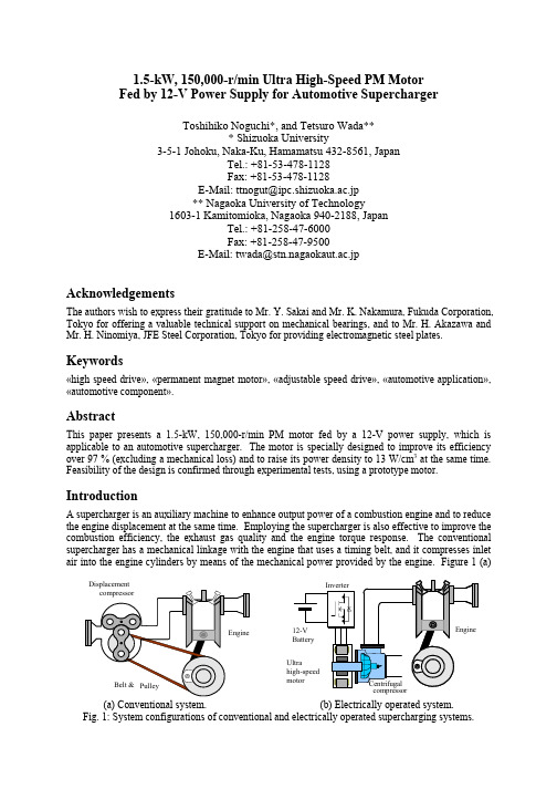
1.5-kW, 150,000-r/min Ultra High-Speed PM Motor Fed by 12-V Power Supply for Automotive SuperchargerToshihiko Noguchi*, and Tetsuro Wada*** Shizuoka University3-5-1 Johoku, Naka-Ku, Hamamatsu 432-8561, JapanTel.: +81-53-478-1128 Fax: +81-53-478-1128E-Mail: ttnogut@ipc.shizuoka.ac.jp ** Nagaoka University of Technology1603-1 Kamitomioka, Nagaoka 940-2188, JapanTel.: +81-258-47-6000 Fax: +81-258-47-9500E-Mail: twada@stn.nagaokaut.ac.jpAcknowledgementsThe authors wish to express their gratitude to Mr. Y. Sakai and Mr. K. Nakamura, Fukuda Corporation, Tokyo for offering a valuable technical support on mechanical bearings, and to Mr. H. Akazawa and Mr. H. Ninomiya, JFE Steel Corporation, Tokyo for providing electromagnetic steel plates.Keywords«high speed drive», «permanent magnet motor», «adjustable speed drive», «automotive application», «automotive component».AbstractThis paper presents a 1.5-kW, 150,000-r/min PM motor fed by a 12-V power supply, which is applicable to an automotive supercharger. The motor is specially designed to improve its efficiency over 97 % (excluding a mechanical loss) and to raise its power density to 13 W/cm 3 at the same time. Feasibility of the design is confirmed through experimental tests, using a prototype motor.IntroductionA supercharger is an auxiliary machine to enhance output power of a combustion engine and to reduce the engine displacement at the same time. Employing the supercharger is also effective to improve the combustion efficiency, the exhaust gas quality and the engine torque response. The conventional supercharger has a mechanical linkage with the engine that uses a timing belt, and it compresses inletair into the engine cylinders by means of the mechanical power provided by the engine. Figure 1 (a)Fig. 1: System configurations of conventional and electrically operated supercharging systems.illustrates a mechanical configuration of the conventional supercharging system. As shown in the figure, many of the superchargers employ a positive displacement compressor because its operation speed is limited by a low revolution speed of the engine. However, the positive displacement compressor has drawbacks such as lower efficiency and lower boost pressure than those of a centrifugal compressor, which prevents further performance improvement of the supercharging system. In order to solve these problems, electrification of the supercharger is significantly important and is very promising approach as a next-generation auxiliary machine system for future automobiles. Figure 1 (b) shows an outline of the electrically operated supercharging system where an ultra high-speed permanent magnet (PM) motor is used to drive the centrifugal compressor instead of the conventional positive displacement compressor. Since the electrically operated supercharger allows use of the centrifugal compressor and makes a mechanical-linkage-free system possible, many advantages are obtained, e.g., more efficient operation, higher rotation speed, higher boost pressure, faster response of the inlet air compression, and smaller mechanical dimensions than those of the conventional displacement compressor based system. Furthermore, such a mechanical-linkage-free design gives freedom of mechanical placement around the engine, and makes it possible to reduce overall mechanical losses as well as to eliminate the complicated linkage mechanism.This paper discusses an optimum design of the ultra high-speed PM motor of which specific application is the electrically operated supercharger of the automotive engine. The motor is fed by a three-phase inverter with a 12-V battery as a DC power supply for an automotive application; thus the motor design must meet a high-current and high-frequency operation requirement without sacrificing the motor efficiency and power density. The investigated motor has a rated output power of 1.5 kW and the maximum rotation speed of 150,000 r/min, respectively. In order to achieve this goal, various technical issues must be solved, e.g., drastic reduction of the synchronous impedance, minimization of the iron and the copper losses, further improvement of the motor efficiency and the power density, mechanical stabilization in high-speed operation range, and so forth. In addition, these electrical design requirements must be satisfied all together with a compact and robust mechanical design. On the way of optimization process in the machine design, a finite element method (FEM) based electromagnetic field analysis is conducted to make fine-tuning of the detailed motor shape and to maximize the efficiency and the power density at the same time. Consequently, the efficiency has been improved over 97 % (excluding a mechanical loss) and the power density has been raised to approximately 13 W/cm3 in the prototype motor design.Required Specifications of Ultra High-Speed PM MotorAssuming a 1,500-cc class automotive engine, the ultra high-speed PM motor is required to have the rated power of 1.5 kW at the maximum rotation speed of 150,000 r/min to achieve the electrically operated supercharging system. When boosting the inlet air compression, extremely fast response is required because the compressor must be accelerated from several ten thousand r/min to the maximum rotation speed in approximately 0.5 s, which surpasses a response time of the conventional supercharger. In order to meet this requirement, the motor must have a short-duration overload capacity, which is a double of the rated output power for 1 s. Table I shows target specifications of the motor determined by the above requirement.Basic Design Concept of Ultra High-Speed PM MotorIn order to achieve the highest efficiency and the highest power density among various sorts of electric motors, a two-pole three-phase surface permanent-magnet synchronous motor (SPMSM) is focused on Table I: Specifications of developed ultra high-speed PM motorAssumed engine 1500 cc classRated output power 1.5 kWMaximum rotation speed 150,000 r/minRated torque 0.0955 NmOverload capacity and duration 3 kW (200 % load) for 1 sas the best choice for the ultra high-speed motor drive because of the simple rotor structure and no magnetizing current required, which implies higher efficiency than other motors.The stator has a six-tooth six-slot structure and concentrated windings, which is remarkably effective to reduce the copper loss and the leakage inductance thoroughly as well as the synchronous inductance. Each phase has a pair of single or double-turned windings in parallel, and the windings are not ordinary wires but copper bars of which shape is like an alphabetical letter “b.” It is necessary to reduce as much stator iron loss as possible even at 150,000 r/min operation, so high-performance 6.5-% silicon electromagnetic steel plates of which thickness is only 0.1 mm are employed to compose a laminated stator iron core.On the other hand, the rotor consists of a strong Nd-Fe-B permanent magnet and a molybdenum alloy shaft. Use of the Nd-Fe-B permanent magnet allows not only motor efficiency improvement but also drastic reduction of the rotor size and inertia. In addition, such a strong Nd-Fe-B permanent magnet that has BH max = 310-kJ/m 3 makes it possible to widen the air gap, which is essential to reduce the synchronous inductance and to obtain a sinusoidal electromotive force (e.m.f.) regardless of the concentrated stator winding structure.Table II is a summary of the basic conceptual design parameters of the ultra high-speed PM motor to be investigated in this paper.Optimization of Permeance Coefficient and Stator WindingsSince a permeance coefficient determines an operating point on a B-H curve of the permanent magnet, operation characteristics of the PM motor dominantly depend on the permeance coefficient. The permeance coefficient is basically proportional to the e.m.f. unless other physical dimensions of the investigated motor are changed. Therefore, the permeance coefficient has a strong influence on the motor efficiency because there is a trade-off relationship between the copper loss and the iron loss of the motor, depending on the e.m.f. Assuming that the investigated PM motor has a uniform permeance distribution along the air gap, the permeance coefficient p u of the motor is expressed by the following equation:gC g m mmmgC g mm u K D D K a a p ll l l l l +−==, (1)where ℓm is a permanent-magnet thickness, a m is an averaged cross section area of the permanentmagnet, a g is an averaged cross section area of the air gap between the rotor and the stator, ℓg is a radial air gap length, D m is an outer diameter of the permanent magnet, and K C is a Carter’s coefficient. Since K C normally takes a value of approximately 1.2 to 1.5, a g can be regarded as almost same as a m K C ; thus, the following approximated expression is obtained:g m u p l l≈. (2)This equation shows that the permeance coefficient is determined by the ratio between the permanent-magnet thickness and the radial air gap length as illustrated in Fig. 2.Table II: Conceptual design parameters of developed ultra high-speed PM motorMotor type Surface Permanent-Magnet Synchronous Motor (SPMSM)Number of phases 3 phase Number of poles 2 pole Stator winding configuration ConcentratedWinding configuration 1- or 2-turn windings in parallel per phaseElectromagnetic steel plates10JNEX900(0.1-mm thick, 6.5-% silicon, µs = 23,000, B max = 1.8 T)Permanent magnetNd-Fe-B N-39SH(Br = 1.28 T, bHc = 955 kA/m, BH max = 310 kJ/m 3)BearingsAngular ceramic-ball bearings with grease lubricationThe synchronous impedance of the investigated PM motor must ultimately be reduced because the motor is operated under high-current and high-frequency operation conditions. Otherwise, it is impossible to satisfy the target specifications, delivering the rated power of 1.5 kW at the maximum rotation speed of 150,000 r/min with a 12-V DC power supply. This ultimately low synchronous impedance can be accomplished by having a wide air gap owing to such a strong Nd-Fe-B permanent magnet as BH max = 310 kJ/m 3, and by reducing the number of winding turns drastically. Figure 3 (a) indicates a stator winding configuration, where two models of the winding structure are illustrated in the same figure, i.e., a one-turn and a two-turn structures. The copper-bar windings are cut out of bulk copper plates so that their shape is like an alphabetical letter “b” as illustrated in Fig. 3 (b). The leakage inductance can effectively be reduced by inserting these windings closely to teeth of the stator iron core.In general, a back e.m.f. of the PM motor is expressed as follows:g w N k p E e φω22==,(3)where p is the number of pole pairs, ω is an operation speed in rad/s, k w is a winding coefficient, N is the number of winding turns and φg is an air gap magnetic flux. As the above equation indicates, the back e.m.f. can be enlarged by increasing Ν or φg . Therefore, the two configurations of the stator windings shown in Fig. 3 (a) are investigated from the viewpoint of the efficiency and power density maximization and the voltage utilization of the inverter output. Suppose that each motor line current is controlled to be in phase with the back e.m.f. of the corresponding phase, the total phase voltage including a voltage drop of the inverter can be expressed by the following equation:E I L I R I R V a a FET +++=ωj ,(4)where R FET I is a voltage drop of the MOSFETs used in the inverter (approximately 2 m Ω/phase), R a I is a voltage drop of the stator winding resistance, ωL a I is a voltage drop of the stator winding inductance, and E is the back e.m.f. The voltage drops of the motor with one-turn stator windings are listed in the left column of Table III. As can be seen in the table, the voltage drop due to the synchronousinductance is hardly observed as well as the leakage inductance drop. In addition, the back e.m.f. ismFig. 2: Cross section diagram to investigate permeance coefficient.2 turnWinding Stator teeth(a) Stator core and windings. (b) Stator winding.Fig. 3: Stator winding configuration.unnecessarily too low to utilize the DC power supply voltage. Therefore, since both of the leakage inductance and the synchronous inductance are sufficiently small, it is possible to operate the motor with a 12-V DC power source even if the number of turn is double as indicated in the upper part of Fig. 3 (a), resulting in quadruple synchronous inductance and twice in the back e.m.f. In addition, changing the permeance coefficient p u from 1.67 to 0.882 to improve the motor efficiency, the voltage drops of the motor with the two-turn stator windings are as listed in the right column of Table III. As described previously, the winding resistance and the inductance become 4 times of those in the one-turn motor, but the increase of these voltage drops can be restricted within 2.5 times to 2.9 times because the operating current is effectively reduced by approximately 30 % by optimizing the back e.m.f. Assuming that the maximum phase voltage applied to the motor is 4.9 V rms , which can be fed by the inverter with the 12-V DC power supply, it is possible to utilize 90.0 % of the 12-V power supply voltage at 1.5-kW operation and to utilize 97.5 % even in a 200-% over load condition without a voltage saturation.Optimization of Detailed Dimensions for Power Density MaximizationIn order to maximize the power density of the motor without sacrificing the efficiency, the detailed stator iron core shape, i.e., a yoke width, a outer diameter and a tooth width, is investigated through FEM based electromagnetic analyses as shown in Fig. 4. The stator inner diameter is fixed at 28 mm, which is derived from the calculation result of the permeance coefficient described above and the stack length of the stator iron core is limited to 30 mm to prevent harmful mechanical vibrations of theO u t e r d i a m e t e r ( 70 m m )ShaftWinding Teeth widthFig. 4: Cross section diagram of 2-turn PM motor.Table III: Voltage drops per phase at rated operation and other design parametersNumber of winding turns 12Resistance of inverter MOSFET R FET2 m ΩStator winding resistance R a 0.072 m Ω 0.200 m Ω Stator winding inductance L a 0.070 µH 0.294 µH Voltage drop of inverter MOSFET R FET I 0.353 V 0.243 V Voltage drop of the stator winding resistance R a I 0.0127 V 0.0243 V Voltage drop of the stator winding inductance ωL a I0.194 V 0.562 V Back e.m.f. E 2.84 V 4.11 V Total voltage drop V 3.21 V 4.41 V Stator iron core stack length L 30 mmPermanent-magnet thickness ℓm5 mm 3.75 mm Radial air gap length ℓg3 mm4.25 mmPermeance coefficient p u 1.67 0.882rotor shaft over the whole operation speed range. Figure 5 shows loss analysis results of the motor with respect to the specified dimension of the stator iron core.Figure 5 (a) shows electrical losses of the motor when only the stator yoke width is changed while other parameters, i.e., the stator outer diameter and the tooth width, are kept constant. As the stator yoke gets wider, the iron loss gradually decreases because the magnetic flux density is reduced in the iron core, but the copper loss becomes dominant among the losses. Since the copper loss is affected by the slot cross section area for the windings, the wider stator yoke reduces the slot cross section area, resulting in higher current density and higher resistance of the windings. On the other hand, when the stator yoke is too narrow, the motor is unable to deliver the torque due to the magnetic saturation in the stator yoke. Therefore, it can be found that 6 mm is the best value for the stator yoke width.Keeping the stator yoke width at 6 mm, a loss analysis result is shown in Fig. 5 (b) as the stator outer diameter is changed. The reduction of the stator outer diameter makes the total iron core loss less because the magnetic flux path gets shorter together with whole volume of the motor. However, the percentage of the copper loss becomes more remarkable as the stator outer diameter gets smaller. The reason of this copper loss enlargement is excessive reduction of the slot cross section area for the windings. Therefore, the stator outer diameter of 70 mm takes the minimum loss, which is the most effective to optimize the overall motor dimensions from the viewpoint of the efficiency and the power density.L o s s (W )Back yoke width (mm)(a) Loss analysis result with respect to back yoke width.L o s s(W )Stator core outer diameter (mm)(b) Loss analysis result with respect to stator outer diameter.102030405060L o s s (W )Teeth width (mm)(c) Loss analysis result with respect to teeth width.Fig. 5: Loss analysis results with respect to detailed stator iron core shape.In a similar way, the tooth width can be determined to be 10 mm to minimize the total loss. As the tooth width gets narrower, it is found that the eddy current loss on the rotor permanent magnet becomes higher. This is because the wider slot opening due to the narrower tooth causes more detrimental permeance variation along the air gap.Consequently, the detailed stator iron core and rotor dimensions are summarized as listed in Table IV. Since the total volume of the stator and the rotor including the air gap is only 115.5 cm3, the power density at the rated output power reaches 13W/cm3, which is approximately 10 times of that of common electric machines. The outer diameter of the rotor is as small as 19.5 mm; thus, the circumference velocity of the rotor reaches 153.2 m/s, which is less than half of the sound speed. As described later on, however, the rotor is mechanically reinforced by glass fiber threads with epoxy resin to prevent the permanent magnet rotor from destruction due to large centrifugal force.Figure 6 shows loss comparison at the rated operating condition between the one-turn and the two-turn motors designed in this investigation. As can be seen in the figure, the two-turn motor achieves drastic reduction of the electrical losses down to 36 W, compared with those of the one-turn motor, i.e., 62 W. The copper loss of the two-turn motor is enlarged because of the small slot cross section area, but each of the eddy current loss on the rotor permanent magnet and the stator iron core loss is effectively reduced. It is inferred that the total efficiency of the designed two-turn motor excluding a mechanical loss reaches 97.6 % although the motor is driven by such a low-voltage DC power supply as a 12-V battery.Prototype Ultra High-Speed PM MotorAs described in the basic design concept, the prototype has a special electrical and mechanical structure. Figure 7 shows photographs of the prototype. The laminated stator iron core consists of approximately 300 sheets of 6.5-% silicon electromagnetic steel plates, of which outer diameter is 70 mm, inner diameter is 28 mm, and axial stack length is 30 mm. The stator winding copper bars are inserted in the stator teeth with keeping electrical insulation from the stator iron core by polyimide taping, and are connected to a neutral-point end ring all together. Each of the stator windings has a cross section area of 16 mm2, resulting in a current density of 7.6 A/mm2 at the rated operating condition. Every clearance between each tooth and each stator winding is less than 0.3 mm, which effectively improves the magnetic coupling with reducing the leakage flux.On the other hand, the rotor is simply assembled with a ring-shaped Nd-Fe-B permanent magnet and a molybdenum alloy shaft, and is magnetized so that the flux distribution becomes sinusoidal. After assembling the rotor, 2.5-mm thick layer of the non-electrically-conductive glass fiber is formed with special epoxy resin on the permanent magnet surface against large centrifugal force. Mechanical reinforcement with glass fiber can be seen in the photograph of the rotor exterior.Table IV: Summary of designed dimensionsStator outer diameter DO70 mm Stator stack length L 30mmmm Stator inner diameter DI28 mm Rotor PM outer diameter dO 19.5mm Rotor PM thickness mStator yoke width YW 6l 3.75 mmmm Radial air gap length g l 4.25 mm Stator tooth width TW 10Fig. 6: Loss comparison between one-turn and two-turn motors at rated operating condition.Figure 8 illustrates a three-dimensional computer graphic (a bird’s-eye view) of the prototype motor assembly. All of the metal components are made with a high-precision NC machining tools. The prototype is designed and created to have extremely high mechanical accuracy of µm-order, especially in the bearing brackets and the rotor shaft parts.Experimental Setup and Test ResultsFigure 9 shows a schematic diagram of an experimental setup to confirm basic operation characteristics of the prototype motor. A pseudo current-source inverter was employed to drive the motor because of a high-fundamental-frequency over 2 kHz and extremely low-synchronous inductance. The pseudo current-source inverter consists of a current-controlled buck-boost chopper and a six-step inverter. The former is operated with a DC-bus current feedback at a switching frequency of 48 kHz, resulting in significant reduction of the DC-bus reactor inductance. The latter commutates the DC-bus current and generates 120-deg conduction patterns of the motor line currents. Surge voltages during the current commutation are clamped by the DC-bus power source via MOSFETs’ body diodes and a bypass diode in the chopper.Table V represents comparison between the designed and the measured motor parameters. As listed here, the measured motor inductance is slightly higher than the designed value because of the leakage inductance and the line inductance to the motor.(a) Stator iron core with two-turn windings. (b) Nd-Fe-B PM rotor reinforced by glass fiber.(c) Front and rear views of assembled motor.Fig. 7: Photographs of prototype ultra high-speed PM motor.Fig. 8: Three-dimensional computer graphic of motor assembly.Figure 10 shows steady-state waveforms of the Hall-effect position sensor signal, the line current and the terminal voltage of the motor operated at 150,000 r/min under no load condition. As can be seen in the figure, the 120-deg current pattern is properly generated in synchronism with the Hall-effect position sensor signal. The motor terminal voltage is sinusoidal without a conspicuous harmonic distortion, which implies the back e.m.f. is properly generated so as to be a sinusoidal waveform by the rotor permanent magnet regardless of the concentrated winding structure of the stator.Figure 11 shows an acceleration test result, which was conducted to examine the output torque controllability. Since measuring the mechanical output at such an ultra high-speed as 150,000 r/min is rather difficult, the output torque of the prototype motor was estimated by a designed value of the rotor inertia and an acceleration observed in the speed step response. As shown in the figure, it is inferred that the maximum output torque delivered for the acceleration was approximately 0.08 Nm due to the current limit of the inverter, which was 84 % of the rated value. Although the estimated output torque waveform is choppy, it can be found from the waveform envelope that the speed is linearly regulated. ConclusionThis paper discussed an optimum design to develop a 1.5-kW, 150,000-r/min ultra high-speed PM motor fed by a 12-V DC power source, which is applicable to an automotive supercharger, from the viewpoint of efficiency and power density improvement. The prototype has various unique features in its electrical and mechanical structure, which achieves a low-voltage, high-current and high-frequency operation. Owing to the optimum design of the permeance coefficient and the detailed stator iron core shape, the designed motor can achieve an ultimately high power density of 13 W/cm3 together with a remarkably high efficiency over 97 % (excluding a mechanical loss). The maximum-speed operation under no-load condition and a speed step response with a 84-% output torque delivered were experimentally examined, and proper operation characteristics were confirmed through the experimental tests.ωmTable V: Measurement result of two-turn motor parametersMotor parameters Designed value Measured valueE.m.f constant 2.74 x 10⁻⁵ V/r/min 2.67 x 10⁻⁵ V/r/minStator winding resistance R a0.200 mΩ 0.151mΩµHStator winding inductance L a0.294 µH 0.362References[1] M. Okawa, "Design Manual of Magnetic Circuit and PM Motor," Sogo Research , 1989 (in Japanese).[2] I. Takahashi, T. Koganezawa, T. Su G., and K. Ohyama, “A Super High Speed PM Motor Drive System by a Quasi-Current Source Inverter,” IEEE Transactions on Industry Applications , Vol. 30, no. 3, p.p. 683-690, 1994. [3] B. -H. Bae, and S. -K. Sul, “A Compensation Method for Time Delay of Full-Digital Synchronous Frame Current Regulator of PWM AC Drives,” IEEE Transactions on Industry Applications , Vol. 39, no. 3, p.p. 802-810, 2003.[4] B. -H. Bae, S. -K. Sul, J. -H. Kwon, and J. -S. Byeon, “Implementation of Sensorless Vector Control for Super-High-Speed PMSM of Turbo-Compressor,” IEEE Transactions on Industry Applications , Vol. 39, no. 3, p.p. 811-818, 2003.[5] T. Noguchi, Y. Takata, Y. Yamashita, Y. Komatsu, and S. Ibaraki, "220000r/min, 2-kW Permanent Magnet Motor Drive for Turbocharger", IEE-Japan International Power Electronics Conference (IPEC2005) -Niigata , p.p. 2280-2285, 2005.[6] C. Zwyssig, M. Duerr, D. Hassler, and J. W. Kolar, “An Ultra-High-Speed, 500000 rpm, 1 kW Electrical Drive System,” The Fourth Power Conversion Conference (PCC2007) -Nagoya , CDROM, 2007.[7] T. Noguchi, and M. Kano, “Development of 150000 r/min, 1.5 kW Permanent-Magnet Motor for Automotive Supercharger,” The Seventh International Conference on Power Electronics and Drive Systems (PEDS2007) -Bangkok , 2A-03, 2007.0.00.40.8 1.2 1.6 2.0-30-20-100102030-15-10-5051015-20246 L i n e c u r r e n t (A )Time (ms)T e r m i n a l v o l t a g e (V )S e n s o r s i n g n a l (V )Fig. 10: Operating waveforms at 150,000 r/min under no load condition.2000025000300003500040000450000.00.20.40.60.81.00.000.020.040.060.080.10R o t a t i o n s p e e d (r /m i n )E s t i m a t e d o u t p u t t o r q u e (N m )Time (s)Fig. 11: Speed step response and experimentally estimated output torque.。
2010年春季学期研究生课程考试试题Q1 填空题(共10分,每空1分)a)现代信息技术的三大支柱是传感技术、通讯技术和计算机技术,它们分别构成信息系统的“( ①感觉器官)”、“神经”和“(大脑②)”。
b)往往一种量值在传感或检测技术上的突破,会带来对另外一种量值的突破。
例如,约瑟夫森效应器件的出现,不仅解决了对于10-13T超弱(磁场③)的检测,同时还解决了对微弱(电压④)量的检测。
c)汽车气囊安全系统的启动,应该依据汽车安装的(压力⑤)和(加速度⑥)等传感器输出的信号值。
d)传感技术的发展主要体现在以下几个方面,如集成化智能化、无线化(网络⑦)化、微机械微(电子⑧)化。
e)传感器结构设计采用反馈形式,可以使传感器的延迟时间常数(变小⑨);采用双敏感元件差动方式,不仅可以改善传感器的非线性问题,还可以抑制例如(温度⑩)等变量参数的干扰。
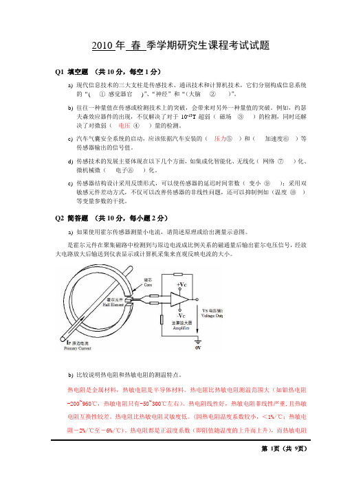
Q2 简答题(共10分,每小题2分)a)如果使用霍尔传感器测量小电流,请简述原理或给出测量示意图。
是霍尔元件在聚集磁路中检测到与原边电流成比例关系的磁通量后输出霍尔电压信号,经放大电路放大后输送到仪表显示或计算机采集来直观反映电流的大小。
b)比较说明热电阻和热敏电阻的测温特点。
热电阻是金属材料,热敏电阻是半导体材料。
热电阻比热敏电阻测温范围大(如铂热电阻-200~960℃,热敏电阻只有-50~300℃左右)。
热电阻线性好,热敏电阻非线性严重,且热敏电阻互换性较差。
热电阻比热敏电阻灵敏度低。
(因热电阻温度系数较小,<1%/℃;热敏电阻-2%/℃至-6%/℃)。
热电阻都是正温度系数(即阻值随温度的上升而上升),而热敏电阻分为负温度系数和正温度系数两种。
c) 无线传感器网络的核心技术问题有哪些?答:关键技术:拓扑控制、网络协议、网络安全、时间同步、定位技术、数据融合、数据管理、无线通信技术、嵌入式系统、应用层技术。
核心问题:能源、传感器、封装、部署、资源受限下的网络机制、大规模下的网络机制d) 功能型光纤传感器可以测量哪些物理量?(举3例即可)答:陀螺、声、磁、压力、温度、液面、e) 在传感器静态特性数据分析中,插值和回归的目的分别是什么?答:插值的目的在于减少或增大信息量。

用纳米做的翅膀英语作文Nano-engineered Wings: Mimicking Nature's Flight.The realm of flight has fascinated humans for centuries, inspiring countless innovations and scientific advancements. While traditional aircraft have enabled us to soar through the skies, the quest for more efficient and sustainable modes of aerial locomotion continues to push the boundaries of engineering and materials science. In recent years, the advent of nanotechnology has opened up new possibilitiesfor the design and fabrication of ultra-lightweight, high-performance wings.Biomimicry and Nature's Inspiration.Nature has long been a source of inspiration for engineers, particularly in the field of flight. Birds and insects, with their remarkable aerial abilities, have evolved intricate wing structures that allow them toachieve exceptional maneuverability, speed, and energyefficiency. By studying these biological counterparts, scientists have gained valuable insights into the design principles that underpin efficient flight.One of the key lessons learned from nature is the importance of low weight and high strength. Birds, for instance, possess lightweight bones and hollow structures that minimize weight while maintaining structural integrity. Insects, on the other hand, utilize a layered cuticlesystem that combines strength and flexibility. Thesenatural designs have served as blueprints for the development of nano-engineered wings.Materials for Nano-winged Flight.The emergence of nanomaterials has provided engineers with a new palette of materials to work with. Carbon nanotubes, graphene, and other nanomaterials possess exceptional strength-to-weight ratios and extraordinary mechanical properties. These materials can be manipulatedat the nanoscale to create ultra-lightweight structureswith tailored properties.For example, researchers at the University of California, Berkeley, have developed a nano-engineered wing made of carbon nanotubes. This wing is incredibly lightweight, weighing only a few milligrams, yet it is also extremely strong and durable. The nanostructured design mimics the hierarchical structure of bird feathers, with nanoscale pores that reduce drag and enhance lift.Aerodynamic Performance and Flight Optimization.The aerodynamic performance of nano-engineered wings is a crucial factor in achieving efficient flight. Scientists are employing computational modeling and wind tunneltesting to optimize wing shapes and surfaces for maximumlift and reduced drag. The nano-scale precision of these materials allows for the creation of intricate aerodynamic features, such as micro-grooves and micro-ridges, that enhance airflow and reduce turbulence.In addition, researchers are exploring the use ofactive materials, such as shape-memory polymers, to enablewings to adapt their shape in response to varying flight conditions. These smart materials can be programmed to adjust the wing's camber and twist, improving maneuverability and stability during different flight phases.Applications and Future Prospects.The potential applications of nano-engineered wings are vast. They could lead to the development of:Autonomous micro air vehicles (MAVs): Small, unmanned flying devices with enhanced flight performance for surveillance, reconnaissance, and inspection tasks.Bio-inspired drones: Drones with wings that mimic the aerodynamic and structural properties of birds, enabling long-range flight and enhanced agility.High-altitude wind turbines: Ultra-lightweight wind turbines with wings designed for maximum lift at high altitudes, generating clean and sustainable energy.Biomedical implants: Nano-engineered wings could be used to create miniature medical devices, such as implantable sensors and drug delivery systems, that can navigate through the body with precision.The development of nano-engineered wings is still in its early stages, but the potential for transformative applications across various industries is immense. By harnessing the power of nanotechnology and drawing inspiration from nature, scientists and engineers are pushing the boundaries of flight and opening up new frontiers in aerial technology.。

自适应分割的视频点云多模式帧间编码方法陈 建 1, 2廖燕俊 1王 适 2郑明魁 1, 2苏立超3摘 要 基于视频的点云压缩(Video based point cloud compression, V-PCC)为压缩动态点云提供了高效的解决方案, 但V-PCC 从三维到二维的投影使得三维帧间运动的相关性被破坏, 降低了帧间编码性能. 针对这一问题, 提出一种基于V-PCC 改进的自适应分割的视频点云多模式帧间编码方法, 并依此设计了一种新型动态点云帧间编码框架. 首先, 为实现更精准的块预测, 提出区域自适应分割的块匹配方法以寻找最佳匹配块; 其次, 为进一步提高帧间编码性能, 提出基于联合属性率失真优化(Rate distortion optimization, RDO)的多模式帧间编码方法, 以更好地提高预测精度和降低码率消耗. 实验结果表明, 提出的改进算法相较于V-PCC 实现了−22.57%的BD-BR (Bjontegaard delta bit rate)增益. 该算法特别适用于视频监控和视频会议等帧间变化不大的动态点云场景.关键词 点云压缩, 基于视频的点云压缩, 三维帧间编码, 点云分割, 率失真优化引用格式 陈建, 廖燕俊, 王适, 郑明魁, 苏立超. 自适应分割的视频点云多模式帧间编码方法. 自动化学报, 2023, 49(8):1707−1722DOI 10.16383/j.aas.c220549An Adaptive Segmentation Based Multi-mode Inter-frameCoding Method for Video Point CloudCHEN Jian 1, 2 LIAO Yan-Jun 1 WANG Kuo 2 ZHENG Ming-Kui 1, 2 SU Li-Chao 3Abstract Video based point cloud compression (V-PCC) provides an efficient solution for compressing dynamic point clouds, but the projection of V-PCC from 3D to 2D destroys the correlation of 3D inter-frame motion and re-duces the performance of inter-frame coding. To solve this problem, we proposes an adaptive segmentation based multi-mode inter-frame coding method for video point cloud to improve V-PCC, and designs a new dynamic point cloud inter-frame encoding framework. Firstly, in order to achieve more accurate block prediction, a block match-ing method based on adaptive regional segmentation is proposed to find the best matching block; Secondly, in or-der to further improve the performance of inter coding, a multi-mode inter-frame coding method based on joint at-tribute rate distortion optimization (RDO) is proposed to increase the prediction accuracy and reduce the bit rate consumption. Experimental results show that the improved algorithm proposed in this paper achieves −22.57%Bjontegaard delta bit rate (BD-BR) gain compared with V-PCC. The algorithm is especially suitable for dynamic point cloud scenes with little change between frames, such as video surveillance and video conference.Key words Point cloud compression, video-based point cloud compresion (V-PCC), 3D inter-frame coding, point cloud segmentation, rate distortion optimization (RDO)Citation Chen Jian, Liao Yan-Jun, Wang Kuo, Zheng Ming-Kui, Su Li-Chao. An adaptive segmentation based multi-mode inter-frame coding method for video point cloud. Acta Automatica Sinica , 2023, 49(8): 1707−1722点云由三维空间中一组具有几何和属性信息的点集构成, 通常依据点的疏密可划分为稀疏点云和密集点云[1]. 通过相机矩阵或高精度激光雷达采集的密集点云结合VR 头盔可在三维空间将对象或场景进行6自由度场景还原, 相较于全景视频拥有更真实的视觉体验, 在虚拟现实、增强现实和三维物体捕获领域被广泛应用[2−3]. 通过激光雷达反射光束经光电处理后收集得到的稀疏点云可生成环境地收稿日期 2022-07-05 录用日期 2022-11-29Manuscript received July 5, 2022; accepted November 29, 2022国家自然科学基金(62001117, 61902071), 福建省自然科学基金(2020J01466), 中国福建光电信息科学与技术创新实验室(闽都创新实验室) (2021ZR151), 超低延时视频编码芯片及其产业化(2020年福建省教育厅产学研专项)资助Supported by National Natural Science Foundation of China (62001117, 61902071), Fujian Natural Science Foundation (2020J01466), Fujian Science & Technology Innovation Laborat-ory for Optoelectronic Information of China (2021ZR151), and Ultra-low Latency Video Coding Chip and its Industrialization (2020 Special Project of Fujian Provincial Education Depart-ment for Industry-University Research)本文责任编委 刘成林Recommended by Associate Editor LIU Cheng-Lin1. 福州大学先进制造学院 泉州 3622512. 福州大学物理与信息工程学院 福州 3501163. 福州大学计算机与大数据学院/软件学院 福州 3501161. School of Advanced Manufacturing, Fuzhou University, Quan-zhou 3622512. College of Physics and Information Engineer-ing, Fuzhou University, Fuzhou 3501163. College of Com-puter and Data Science/College of Software, Fuzhou University,Fuzhou 350116第 49 卷 第 8 期自 动 化 学 报Vol. 49, No. 82023 年 8 月ACTA AUTOMATICA SINICAAugust, 2023图, 以实现空间定位与目标检测等功能, 业已应用于自动驾驶、无人机以及智能机器人等场景[4−7]. 但相较于二维图像, 点云在存储与传输中的比特消耗显著增加[8], 以经典的8i 动态点云数据集[9]为例, 在每秒30帧时的传输码率高达180 MB/s, 因此动态点云压缩是对点云进行高效传输和处理的前提.N ×N ×N 3×3×3为了实现高效的动态点云压缩, 近年来, 一些工作首先在三维上进行帧间运动估计与补偿, 以充分利用不同帧之间的时间相关性. 其中, Kammerl 等[10]首先提出通过构建八叉树对相邻帧进行帧间差异编码, 实现了相较于八叉树帧内编码方法的性能提升; Thanou 等[11]则提出将点云帧经过八叉树划分后, 利用谱图小波变换将三维上的帧间运动估计转换为连续图之间的特征匹配问题. 然而, 上述方法对帧间像素的运动矢量估计不够准确. 为了实现更精确的运动矢量估计, Queiroz 等[12]提出一种基于运动补偿的动态点云编码器, 将点云体素化后进行块划分, 依据块相关性确定帧内与帧间编码模式, 对帧间编码块使用提出的平移运动模型改善预测误差; Mekuria 等[13]则提出将点云均匀分割为 的块, 之后将帧间对应块使用迭代最近点(Iterative closest point, ICP)[14]进行运动估计,以进一步提高帧间预测精度; Santos 等[15]提出使用类似于2D 视频编码器的N 步搜索算法(N-step search, NSS), 在 的三维块区域中迭代寻找帧间对应块, 而后通过配准实现帧间编码. 然而,上述方法实现的块分割破坏了块间运动相关性, 帧间压缩性能没有显著提升.为了进一步提高动态点云压缩性能, 一些工作通过将三维点云投影到二维平面后组成二维视频序列, 而后利用二维视频编码器中成熟的运动预测与补偿算法, 实现三维点云帧间预测. 其中, Lasserre 等[16]提出基于八叉树的方法将三维点云投影至二维平面, 之后用二维视频编码器进行帧间编码; Bud-agavi 等[17]则通过对三维上的点进行二维平面上的排序, 组成二维视频序列后利用高效视频编码器(High efficiency video coding, HEVC)进行编码.上述方法在三维到二维投影的过程中破坏了三维点间联系, 重构质量并不理想. 为改善投影后的点间联系, Schwarz 等[18]通过法线将点映射于圆柱体上确保点间联系, 对圆柱面展开图使用二维视频编码以提高性能. 但在圆柱上的投影使得部分点因遮挡丢失, 影响重构精度. 为尽可能保留投影点数, Mam-mou 等[19]根据点云法线方向与点间距离的位置关系, 将点云划分为若干Patch, 通过对Patch 进行二维平面的排列以减少点数损失, 进一步提高了重构质量.基于Patch 投影后使用2D 视频编码器进行编码, 以实现二维上的帧间运动预测与补偿的思路取得了最优的性能, 被运动图像专家组(Moving pic-ture experts group, MPEG)正在进行的基于视频的点云压缩(Video-based point cloud compres-sion, V-PCC)标准[20]所采纳, 但将Patch 从三维到二维的投影导致三维运动信息无法被有效利用, 使得帧间压缩性能提升受到限制. 针对这一问题, 一些工作尝试在V-PCC 基础上实现三维帧间预测,其中, Li 等[21]提出了一种三维到二维的运动模型,利用V-PCC 中的几何与辅助信息推导二维运动矢量以实现帧间压缩性能改善, 但通过二维推导得到的三维运动信息并不完整, 导致运动估计不够准确.Kim 等[22]提出通过点云帧间差值确定帧内帧与预测帧, 帧内帧用V-PCC 进行帧内编码, 预测帧依据前帧点云进行运动估计后对残差进行编码以实现运动补偿, 但残差编码依旧消耗大量比特. 上述方法均在V-PCC 基础上实现了三维点云的帧间预测,但无论是基于二维的三维运动推导还是帧间残差的编码, 性能改善都比较有限.在本文的工作中, 首先, 为了改善三维上实现运动估计与补偿中, 块分割可能导致的运动相关性被破坏的问题, 本文引入了KD 树(K-dimension tree,KD Tree)思想, 通过迭代进行逐层深入的匹配块分割, 并定义分割块匹配度函数以自适应确定分割的迭代截止深度, 进而实现了更精准的运动块搜索;另外, 针对V-PCC 中二维投影导致三维运动信息无法被有效利用的问题, 本文提出在三维上通过匹配块的几何与颜色两种属性进行相似性判别, 并设计率失真优化(Rate distortion optimization, RDO)模型对匹配块分类后进行多模式的帧间编码, 实现了帧间预测性能的进一步改善. 实验表明, 本文提出的自适应分割的视频点云多模式帧间编码方法在与最新的V-PCC 测试软件和相关文献的方法对比中均取得了BD-BR (Bjontegaard delta bit rate)的负增益. 本文的主要贡献如下:1)提出了针对动态点云的新型三维帧间编码框架, 通过自动编码模式判定、区域自适应分割、联合属性率失真优化的多模式帧间编码、结合V-PCC 实现了帧间编码性能的提升;2)提出了一种区域自适应分割的块匹配方法,以寻找帧间预测的最佳匹配块, 从而改善了均匀分割和传统分割算法导致运动相关性被破坏的问题;3)提出了一种基于联合属性率失真优化模型的多模式帧间编码方法, 在改善预测精度的同时显著减少了帧间编码比特.1 基于视频的点云压缩及其问题分析本文所提出的算法主要在V-PCC 基础上进行1708自 动 化 学 报49 卷三维帧间预测改进, 因此本节对V-PCC 的主要技术做简要介绍, 并分析其不足之处. 其中, V-PCC 编码框架如图1所示.图 1 V-PCC 编码器框架Fig. 1 V-PCC encoder diagram首先, V-PCC 计算3D 点云中每个点的法线以确定最适合的投影面, 进而将点云分割为多个Patch [23].接着, 依据对应Patch 的位置信息, 将其在二维平面上进行紧凑排列以完成对Patch 的打包. 之后,依据打包结果在二维上生成对应的图像, 并使用了几何图、属性图和占用图分别表示各点的坐标、颜色及占用信息. 鉴于Patch 在二维的排列不可避免地存在空像素点, 因此需要占用图表示像素点的占用与否[24]; 由于三维到二维的投影会丢失一个维度坐标信息, 因此使用几何图将该信息用深度形式进行表示; 为了实现动态点云的可视化, 还需要一个属性图用于表示投影点的颜色属性信息. 最后, 为了提高视频编码器的压缩性能, 对属性图和几何图的空像素进行了填充和平滑处理以减少高频分量; 同时, 为了缓解重构点云在Patch 边界可能存在的重叠或伪影, 对重构点云进行几何和属性上的平滑滤波处理[25]. 通过上述步骤得到二维视频序列后, 引入二维视频编码器(如HEVC)对视频序列进行编码.V-PCC 将动态点云帧进行二维投影后, 利用成熟的二维视频编码技术实现了动态点云压缩性能的提升. 但是, V-PCC 投影过程将连续的三维物体分割为多个二维子块, 丢失了三维上的运动信息,使得三维动态点云中存在的时间冗余无法被有效利用. 为了直观展示投影过程导致的运动信息丢失,图2以Longdress 数据集为例, 展示了第1 053和第1 054两相邻帧使用V-PCC 投影得到的属性图.观察图2可以发现, 部分在三维上高度相似的区域,如图中标记位置1、2与3所对应Patch, 经二维投影后呈现出完全不同的分布, 该结果使得二维视频编码器中帧间预测效果受到限制, 不利于压缩性能的进一步提升.2 改进的动态点云三维帧间编码为了在V-PCC 基础上进一步降低动态点云的时间冗余性, 在三维上进行帧间预测和补偿以最小化帧间误差, 本文提出了一个在V-PCC 基础上改进的针对动态点云的三维帧间编码框架, 如图3所示. 下面对该框架基本流程进行介绍.首先, 在编码端, 我们将输入的点云序列通过模块(a)进行编码模式判定, 以划分帧内帧与预测帧. 其思想与二维视频编码器类似, 将动态点云划分为多组具有运动相似性的图像组(Group of pic-tures, GOP)以分别进行编码. 其中图像组中的第一帧为帧内帧, 后续帧均为预测帧, 帧内帧直接通过V-PCC 进行帧内编码; 预测帧则通过帧间预测方式进行编码. 合理的GOP 划分表明当前图像组内各相邻帧均具有较高运动相关性, 因此可最优化匹配块预测效果以减少直接编码比特消耗, 进而提高整体帧间编码性能. 受文献[22]启发, 本文通过对当前帧与上一帧参考点云进行几何相似度判定,以确定当前帧的编码方式进行灵活的图像组划分.如式(1)所示.Longdress 第 1 053 帧三维示例Longdress 第 1 054 帧三维示例Longdress 第 1 053 帧 V-PCC投影属性图Longdress 第 1 054 帧 V-PCC投影属性图11223图 2 V-PCC 从三维到二维投影(属性图)Fig. 2 V-PCC projection from 3D to2D (Attribute map)8 期陈建等: 自适应分割的视频点云多模式帧间编码方法1709cur ref E Gcur,ref Ωmode mode E O R 其中, 为当前帧点云, 为前帧参考点云, 表示两相邻帧点云的几何偏差, 为编码模式判定阈值. 当 值为1时表示当前帧差异较大, 应当进行帧内模式编码; 当 值为0时则表示两帧具有较大相似性, 应当进行帧间模式编码. 另外, 在动态点云重构误差 的计算中, 使用原始点云 中各点与重构点云 在几何和属性上的误差均值表示, 即式(2)所示.N O O (i )R (i ′)i i ′E O,R O R 其中, 为原始点云点数, 和 分别表示原始点云第 点与对应重构点云 点的几何或属性值, 即为原始点云 与重构点云 间误差值.N ×N ×N K 接着, 在进行帧间编码模式判断后, 通过模块(b)进行预测帧的区域自适应块分割. 块分割的目的在于寻找具有帧间运动一致性的匹配块以进行运动预测和补偿. 不同于 等分或 均值聚类, 所提出的基于KD 树思想的区域自适应块匹配从点云质心、包围盒和点数三个角度, 判断分割块的帧间运动程度以进行分割深度的自适应判定,最终实现最佳匹配块搜索.之后, 对于分割得到的匹配块, 通过模块(c)进行基于联合属性率失真优化的帧间预测. 在该模块中, 我们通过帧间块的几何与颜色属性联合差异度,结合率失真优化模型对匹配块进行分类, 分为几乎无差异的完全近似块(Absolute similar block, ASB)、差异较少的相对近似块(Relative similar block,RSB)以及存在较大差异的非近似块(Non similar block, NSB). 完全近似块认为帧间误差可忽略不计, 仅需记录参考块的位置信息; 而相对近似块则表示存在一定帧间误差, 但可通过ICP 配准和属性补偿来改善几何与属性预测误差, 因此除了块位置信息, 还需记录预测与补偿信息; 而对于非近似块,则认为无法实现有效的帧间预测, 因此通过融合后使用帧内编码器进行编码.最后, 在完成帧间模式分类后, 为了在编码端进行当前帧的重构以作为下一帧匹配块搜索的参考帧, 通过模块(d)对相对近似块进行几何预测与属性补偿, 而后将几何预测与属性补偿后的相对近似块、完全近似块、非近似块进行融合得到重构帧. 为了在解码端实现帧间重构, 首先需要组合预测帧中的所有非近似块, 经由模块(e)的V-PCC 编码器进行帧内编码, 并且, 还需要对完全近似块的位置信息、相对近似块的位置与预测补偿信息通过模块(f)进行熵编码以实现完整的帧间编码流程.至此, 整体框架流程介绍完毕, 在接下来的第3节与第4节中, 我们将对本文提出的区域自适应分割的块匹配算法与联合属性率失真优化的多模式帧间编码方法进行更为详细的介绍, 并在第5节通过实验分析进行算法性能测试.3 区域自适应分割的块匹配N B j cur j ref j ∆E cur j ,ref j 相较于二维视频序列, 动态点云存在大量空像素区域, 帧间点数也往往不同. 因此, 对一定区域内的点集进行帧间运动估计时, 如何准确找到匹配的邻帧点集是一个难点. 假设对当前帧进行帧间预测时共分割为 个子点云块, 第 块子点云 与其对应参考帧匹配块 间存在几何与属性综合误差 . 由于重构的预测帧实质上是通过组合相应的参考帧匹配块而估计得到的, 因此精准的帧间块匹配尝试最小化每个分割块的估计误差,以提高预测帧整体预测精度, 如式(3)所示:图 3 改进的三维帧间编码框架Fig. 3 Improved 3D inter-frame coding framework1710自 动 化 学 报49 卷K K N N ×N ×N 为了充分利用帧间相关性以降低时间冗余, 一些工作尝试对点云进行分割后寻找最佳匹配块以实现帧间预测. Mekuria 等[13]将动态点云划分为若干个大小相同的宏块, 依据帧间块点数和颜色进行相似性判断, 对相似块使用迭代最近点算法计算刚性变换矩阵以实现帧间预测. 然而, 当区域分割得到的对应匹配块间存在较大偏差时, 预测效果不佳.为了减少匹配块误差以提高预测精度, Xu 等[26]提出使用 均值聚类将点云分为多个簇, 在几何上通过ICP 实现运动预测, 在属性上则使用基于图傅里叶变换的模型进行运动矢量估计. 但基于 均值聚类的点云簇分割仅在预测帧中进行, 没有考虑帧间块运动相关性, 匹配精度提升受到限制. 为了进一步提高匹配精度, Santos 等[15]受到二维视频编码器中 步搜索算法的启发, 提出了一种3D-NSS 方法实现三维上的匹配块搜索, 将点云分割为 的宏块后进行3D-NSS 以搜索最优匹配块, 而后通过ICP 进行帧间预测.K 上述分割方法均实现了有效的块匹配, 但是,基于宏块的均匀块分割与基于传统 均值聚类的块划分均没有考虑分割块间可能存在的运动连续性, 在分割上不够灵活. 具体表现为分割块过大无法保证块间匹配性, 过小又往往导致已经具有运动连续性的预测块被过度细化, 出现相同运动预测信息的冗余编码. 为了避免上述问题, 本文引入KD 树思想, 提出了一种区域自适应分割算法, 该算法通过迭代进行逐层深入的二分类划分, 对各分割深度下块的运动性质与匹配程度进行分析, 确定是否需要继续分割以实现精准运动块匹配. 算法基本思想如图4所示, 若满足分割条件则继续进行二分类划分, 否则停止分割.Ψ(l,n )其中, 准确判断当前分割区域是否满足运动连续性条件下的帧间运动, 是避免过度分割以实现精准的运动块搜索的关键, 本文通过定义分割块匹配函数来确定截止深度, 如式(4)所示:ρ(n )=max [sign (n −N D ),0]n N D ρ(n )=1ξ(l )l 其中, 为点数判定函数,当点数 大于最小分割块点数阈值 时, ,表示满足深入分割的最小点数要求, 否则强制截止; 为当前深度 下的块运动偏移度, 通过衡量匹配块间的运动变化分析是否需要进一步分割.ξξw ξu 提出的 函数分别通过帧间质心偏移度 估计匹配块间运动幅度, 帧间包围盒偏移度 进行匹ξn ξw ξu ξn T l ξ(l )配块间几何运动一致性判定, 点数偏移度 进行点云分布密度验证, 最后通过 、 与 累加值与分割截止阈值 的比值来整体衡量当前块的运动程度与一致性. 即对于当前分割深度 , 可进一步细化为式(5):其中,w cur w ref u cur u ref n cur n ref l P Max P Min 并且, 、 、 、 、与分别表示当前分割深度下该区域与其前帧对应区域的质心、包围盒与点数,和分别为当前块对角线对应点.ρ(n )=1ξ(l)lξξξξ在的前提下,值反映当前KD 树分割深度下该区域点云的帧间运动情况.值越大帧间运动越显著,当值大于1时,需对运动块进行帧间运动补偿,如果继续分割将导致块的运动一致性被破坏或帧间对应块无法实现有效匹配,从而导致帧间预测失败;值越小说明当前区域点云整体运动变化越小,当值小于1时,需进一步分割寻找可能存在的运动区域.l +1d 对于需要进一步分割的点云块,为了尽可能均匀分割以避免分割后匹配块间误差过大, 将待分割匹配块质心均值作为分割点, 通过以包围盒最长边作为分割面来确定 深度下的分割轴 , 分割轴l = 0l = 1l = 2l = m l = m + 1条件满足, 继续分割条件不满足, 停止分割图 4 区域自适应分割块匹配方法示意图Fig. 4 Schematic diagram of region adaptive segmentation based block matching method8 期陈建等: 自适应分割的视频点云多模式帧间编码方法1711如式(6)所示:Edge d,max Edge d,min d 其中, 和 分别为待分割块在 维度的最大值和最小值.总结上文所述, 我们将提出的区域自适应分割的块匹配算法归纳为算法1. 算法 1. 区域自适应分割的块匹配cur ref 输入. 当前帧点云 与前帧参考点云 输出. 当前帧与参考帧对应匹配块j =1N B 1) For to Do l =02) 初始化分割深度 ;3) Docur j ref j 4) 选取待分割块 和对应待匹配块 ;w u n 5) 计算质心 、包围盒 与块点数 ;ξ(l )6) 根据式(5)计算运动块偏移度 ;ρ(n )7) 根据函数 判定当前分割块点数;Ψ(l,n )8) 根据式(4)计算分割块匹配函数 ;Ψ(l,n )9) If 满足匹配块分割条件:d 10) 根据式(6)确定分割轴 ;cur j ref j 11) 对 与 进行分割;12) 保存分割结果;l +113) 分割深度 ;Ψ(l,n )14) Else 不满足匹配块分割条件:15) 块分割截止;16) 保存匹配块;17) End of if18) While 所有块均满足截止条件;19) End of for图5展示了本文提出的区域自适应分割的块匹配算法对帧Longdress_0536和其参考帧Longdress_0535进行分割后的块匹配结果. 在该序列当前帧下, 人物进行上半身的侧身动作. 观察图5可发现,在运动变化较大的人物上半身, 算法在寻找到较大的对应匹配块后即不再分割; 而人物下半身运动平缓, 算法自适应提高分割深度以实现帧间匹配块的精确搜索, 因而下半身的分块数目大于上半身.4 联合属性率失真优化的多模式帧间编码P Q在动态点云的帧间编码中, 常对相邻帧进行块分割或聚类后依据匹配块相似性实现帧间预测, 并利用补偿算法减少预测块误差以改善帧间编码质量. 其中迭代最近点算法常用于帧间运动估计中,其通过迭代更新待配准点云 相较于目标点云 S t E (S,t )间的旋转矩阵 和平移向量 , 进而实现误差 最小化, 如式(7)所示:N p p i P i q i ′Q p i 其中 为待配准点云点数, 为待配准点云 的第 个点, 为目标点云 中与 相对应的点.但是, 完全依据ICP 配准进行动态点云的三维帧间预测存在两个问题: 首先, ICP 仅在预测块上逼近几何误差的最小化而没考虑到颜色属性偏差引起的匹配块差异, 影响了整体预测精度; 其次, 从率失真角度分析, 对运动变化极小的匹配块进行ICP 配准实现的运动估计是非必要的, 该操作很难改善失真且会增加帧间编码比特消耗.为改善上述问题, 提出了联合属性率失真优化的多模式帧间编码方法. 提出的方法首先在确保几何预测精度的同时, 充分考虑了可能的属性变化导致的预测精度下降问题, 而后通过率失真优化模型,对块依据率失真代价函数得到的最优解进行分类后, 应用不同的编码策略以优化帧间编码方案, 旨在有限的码率约束下最小化编码失真, 即式(8)所示:R j D j j N B R C λ其中, 和 分别表示第 个点云块的编码码率和对应的失真; 是当前帧编码块总数; 表示总码率预算.引入拉格朗日乘子 ,式(8)所示的带约束优化问题可以转换为无约束的最优化问题, 即式(9)所示:当前帧分割可视化当前帧分割效果参考帧分割效果图 5 区域自适应分割的块匹配方法分割示例Fig. 5 Example of block matching method based onadaptive regional segmentation1712自 动 化 学 报49 卷。
超高分子量聚乙烯纤维生产工艺The production process of ultra-high molecular weight polyethylene (UHMWPE) fibers is a complex and intricate procedure that involves several key steps to ensure the quality and performance of the final product. UHMWPE fibers are known for their exceptional strength, durability, and resistance to abrasion, making them ideal for a wide range of applications, including ballistic protection, ropes and nets, and medical devices. The manufacturing process of UHMWPE fibers requires careful attention to detail and precision to achieve the desired properties and performance characteristics.One of the first steps in the production of UHMWPE fibers is the polymerization of ethylene monomer to form long chains of polyethylene molecules with extremely high molecular weights. This process typically involves the use of a catalyst and high-pressure conditions to promote the growth of the polymer chains. The resulting UHMWPE resin is then extruded into a gel-like form, which is subsequentlystretched and oriented to align the polymer chains in the desired direction. This stretching process is crucial for enhancing the strength and toughness of the fibers, as it helps to eliminate any entanglements or defects in the molecular structure.After the initial stretching and orientation, the UHMWPE fibers undergo a process known as gel spinning,which involves spinning the gel-like material into fine, continuous filaments. This step is critical for producing fibers with high tensile strength and modulus, as it helpsto further align the polymer chains and remove anyremaining imperfections in the molecular structure. Thespun fibers are then subjected to heat treatment to improve their crystallinity and enhance their mechanical properties. This heat treatment process, also known as annealing, helps to increase the degree of crystallinity in the fibers,which in turn improves their tensile strength, stiffness, and resistance to creep and fatigue.In addition to the primary manufacturing steps, the production of UHMWPE fibers also requires careful controland monitoring of various process parameters, such as temperature, pressure, and stretching conditions. These parameters play a crucial role in determining the final properties and performance characteristics of the fibers, and any deviations or inconsistencies in the process can result in inferior product quality. Therefore, it is essential for manufacturers to implement strict quality control measures and process optimization techniques to ensure the uniformity and consistency of the UHMWPE fibers.Furthermore, the production of UHMWPE fibers also involves the use of advanced equipment and machinery, such as extruders, spin-drawing machines, and heat treatment ovens, which require regular maintenance and calibration to ensure their proper functioning. Any malfunctions or deviations in the equipment can have a significant impact on the quality and performance of the fibers, making it essential for manufacturers to invest in state-of-the-art technology and equipment to support their production processes.Overall, the production of UHMWPE fibers is a highlysophisticated and intricate process that requires careful attention to detail, precision, and control of various parameters to achieve the desired properties and performance characteristics. By implementing advanced manufacturing techniques, strict quality control measures, and state-of-the-art equipment, manufacturers can ensure the production of high-quality UHMWPE fibers that meet the stringent requirements of various industrial and commercial applications.。
拓扑优化(topology optimization)1. 基本概念拓扑优化是结构优化的一种。
结构优化可分为尺寸优化、形状优化、形貌优化和拓扑优化。
其中尺寸优化以结构设结构优化类型的差异计参数为优化对象,比如板厚、梁的截面宽、长和厚等;形状优化以结构件外形或者孔洞形状为优化对象,比如凸台过渡倒角的形状等;形貌优化是在已有薄板上寻找新的凸台分布,提高局部刚度;拓扑优化以材料分布为优化对象,通过拓扑优化,可以在均匀分布材料的设计空间中找到最佳的分布方案。
拓扑优化相对于尺寸优化和形状优化,具有更多的设计自由度,能够获得更大的设计空间,是结构优化最具发展前景的一个方面。
图示例子展示了尺寸优化、形状优化和拓扑优化在设计减重孔时的不同表现。
2. 基本原理拓扑优化的研究领域主要分为连续体拓扑优化和离散结构拓扑优化。
不论哪个领域,都要依赖于有限元方法。
连续体拓扑优化是把优化空间的材料离散成有限个单元(壳单元或者体单元),离散结构拓扑优化是在设计空间内建立一个由有限个梁单元组成的基结构,然后根据算法确定设计空间内单元的去留,保留下来的单元即构成最终的拓扑方案,从而实现拓扑优化。
3. 优化方法目前连续体拓扑优化方法主要有均匀化方法[1]、变密度法[2]、渐进结构优化法[3](ESO)以及水平集方法[4]等。
离散结构拓扑优化主要是在基结构方法基础上采用不同的优化策略(算法)进行求解,比如程耿东的松弛方法[5],基于遗传算法的拓扑优化[6]等。
4. 商用软件目前,连续体拓扑优化的研究已经较为成熟,其中变密度法已经被应用到商用优化软件中,其中最著名的是美国Altair公司Hyperworks系列软件中的Optistruc t和德国Fe-design公司的Tosca等。
前者能够采用Hypermesh作为前处理器,在各大行业内都得到较多的应用;后者最开始只集中于优化设计,而没有自己的有限元前处理器,操作较为麻烦,近年来和Ansa联盟,开发了基于Ansa的前处理器,但在国内应用的较少。
超高速永磁同步电机转子护套设计分析及优化韦福东,王建辉,刘朋鹏!上海电器科学研究所(集团)有限公司,上海200063]摘 要:超高速永磁同步电机(PMSM )转速较高,永磁体抗拉强度相对较小,需要在转子永磁体外设置护套并通过过盈配合使永磁体上产生径向压应力,抵消转子高速旋转 产生力,对永磁体 护。
提岀了一种超高速PMSM 转子 磁合金护套厚度及过盈量计算分析方法。
以1台120 000 r/min 超高速PMSM 为例,运法 度 转子静力 合仿真分析,对 法,并通过优化设计,使电机转子在 强度要求的情况下,合理计算护套 度及过盈量,转子护套的厚度,小转子,为超高速电机转子设计。
关键词:超高速永磁同步电机;不导磁合金护套;设计分析中图分类号:TM351文献标志码:A文章编号:1673-6540(2021)05-0060-06doi : 10.12177/emca.2020.229Design Analysis and Optimization of the Rotor Sleeve of Ultra-High-SpeedPermanent Magnet Synchronous Motor *收稿日期:2020-12-11;收到修改稿日期:2021-01-27*基金项目:广东省重点领域研发计划项目(2019(090909002)作者简介:韦福东(1992-),男,硕士,研究方向为电机设计与控制技术。
王建辉(1971-),男,博士,副教授,研究方向为电机设计与控制技术。
刘朋鹏(1990-),男,硕士,研究方向为电机设计与控制技术。
WEI Fudong, WANG Jianhui, LIU Pengpeng[Shanghai Electrical Apparatus Research Institute (Group J Co., Ltd., Shanghai 200063, China]Abstract : The ultra-high-speed permaneni magnet synchronous motoo (PMSM) has the characte/stica of highspeed and relatively low tensile strength of permanent magnets. Therefore, it is necessary to set a sleeve on the outside of the permanent magnet of the rotoc, and generate radial compressive stress on the permanent magnet throughinterference fit, so as t offset the centrifugal force generated during the rotoa high-speed rotation and protect thepermanent magnet. A method foo calculating and analyzing the thickness and interference of rotoo non-magnetic alloy sleeve of the ultra-high-speed PMSM is p roposed. Taking a 120 000 Omin ultra-high-speed PMSM as an example,the coupling simulation of temperature f ield and rotoo staticc is cdried out by using finite element method, and the numericce method is verified. The optimized design is utilized to reasonabty calculate the thickness and interferencc amount of the sleeve undeo the condition that the motoo rotoo meetr the requirementr of structurd strength. It can eaectively reducc the thickness of rotoo sleeve, thus reducing the iron consumption of rotoo, which provides a referenccto rotoo design of ultra-high-speed motoo.Key words: ulha-highspeed permanent magnet synchronous motor (PMSM); non-magnetic alloy sleeve; design analysis0引言高、 度 点,广 应用在超高速空压缩机、数控机床高速电 、 机超高速永磁同步电机(PMSM )具有转速床等设备场合[1 超高速PMSM 转子永磁体永磁,较高抗压强度,抗拉强度和抗弯强度较低、较差2。