
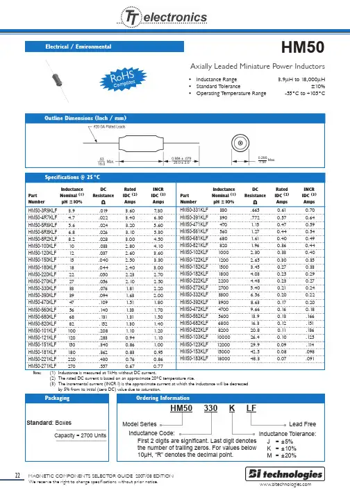
HM50-560MLF中文资料
- 格式:pdf
- 大小:251.96 KB
- 文档页数:1

Cascade ContourBathing Systems with Aqua-Aire® Installation / Assembly Instructions360745C Revision A – 05/01/2013ContentsINTRODUCTION (3)TERMINOLOGY AND SYMBOL MEANINGS (3)PLUMBING REQUIREMENTS (3)SYSTEM CONTROLS CASCADE CONTOUR SPA (4)ROUGN-IN SPECIFICATIONS FOR RIGHT HAND CONTOUR SPA (5)ROUGN-IN SPECIFICATIONS FOR LEFT HAND CONTOUR SPA (5)CASCADE CONTOUR WITH SIDE ENTRY TUB SPA (6)CASCADE CONTOUR WITH END OPENING SPA (7)CASCADE CONTOUR WITH SWIVEL LIFT TUB SPA (8)DRAIN REQUIREMENTS (9)HOT AND COLD WATER SUPPLY REQUIDREMENTS (9)ELECTRICAL REQUIREMENTS (9)UNPACKING THE CONTOUR TUB (9)UNPACKING THE CONTOUR CABINET (9)ASSEMBLY AND INSTALLATION OF THE TUB AND CABINET (10)ANCHORING THE CADSCADE SWIVEL LIFT TUB (11)ANCHORING THE CASCADE CONTOUR CABINET (11)WATER SUPPLY AND DRAIN CONNECTIONS (12)DRAIN REQUIREMENTS (12)HOT AND COLD WATER SUPPLY REQUIREMENTS (12)ELECTRICAL CONNECTIONS (12)SYSTEM CHECKS (13)FINISHING UP (14)INTRODUCTIONThese instructions are for the installation of the Cascade Contour Bathing System Cabinets and Tubs. The Reservoir is included in the cabinet of this system, which is to be pre-filled prior to placing the resident into the tub. Then the water in the reservoir can be released into the tub. This shortens thetime required before the tub is full.When the terms “left” or “right” are used with refer ence to the tub, this means left or right as youlook at the control panel from the seat end of the tub.TERMINOLOGY AND SYMBOL MEANINGSMeaning: Safety warning. Failure to understand and obey this warning may result in injury to you or to others.Meaning: Failure to follow these instructions may cause damage to parts or systems.Note: Refer to the “Tub Controls” figure 1 on page 4 of this manual for the location of any of the controls referenced.PLUMBING REQUIREMENTSIt is required that a licensed plumber make all plumbing connections. He can select the best method of connection and if Reduced Pressure Zone Backflow Preventers are required.SYSTEM CONTROLS CASCADE CONTOUR SPAROUGN-IN SPECIFICATIONS FOR RIGHT HAND CONTOUR SPAFigure 2ROUGN-IN SPECIFICATIONS FOR LEFT HAND CONTOUR SPAFigure 3CASCADE CONTOUR WITH SIDE ENTRY TUB SPAFigure 4Top ViewFigure 4CASCADE CONTOUR WITH END OPENING SPAFigure 5CASCADE CONTOUR WITH SWIVEL LIFT TUB SPAFigure 6DRAIN REQUIREMENTSFigure 2 shows two different options for roughing in the drain pipe – from the floor or from the wall. The tub is equipped with a 2” nominal (2 3/8” O.D.) PVC drain pip e.NOTE: It is required that a licensed plumber make all plumbing connections. He can select the best method of connection for the particular situation and determine if ReducedPressure Zone Backflow Preventers are required.HOT AND COLD WATER SUPPLY REQUIDREMENTS3/4” supply lines with on/off valves with 3/4” NPT Male threads. We recommend 3/4” ball valve with 3/4” NPT female ports. (Valves supplied by others.) See figure 2 for recommendedlocations.For optimum performance, dynamic pressures should be nominally equal between hot and cold supplies.Maximum static supply pressure: 145 PSI.Maximum dynamic/maintained supply pressure: 81 PSI.Maximum supply Hot water temperature: Consult local requirements for maximum allowed supplytemperatures. (Not recommended over 120o F)ELECTRICAL REQUIREMENTSThe Cascade Contour tub Aqua-Air is rated at 7.25 Amps (9.5 Amps for Swivel lift tubs), 120 Volts AC.15 amp GFCI circuit is required.UNPACKING THE CONTOUR TUB1. Remove the Tub from the shipping crate.2. Locate and save the installation parts.UNPACKING THE CONTOUR CABINET1. Remove the Cabinet from the shipping crate.2. Locate and save the installation parts.3. Remove the Top or lid, and the two end panels and place to the side out of the way.ASSEMBLY AND INSTALLATION OF THE TUB AND CABINET1.Place the cabinet approximately 2 feet from the wall directly in front of the intended finallocation.2.Move the tub directly in front of the tub with the foot end of the tub just in front of the tubopening in the cabinet.3.To avoid damaging the seal at the top of the tub opening of the cabinet, tip the cabinet back andthen slide the tub into the opening of the cabinet. Lower the cabinet back down.4.Connect the tub and cabinet frames together with the bolts, flat washer, and hex nuts provided.Use the flat washers under the heads of the bolts and under the hex nuts to protect the powder coated finish of the frames. Note: Some adjustment of the leveling feet of the tub may beneeded to align the bolt holes in the frames.5.Connect the air manifold of the tub to the union connection of the cabinet plumbing locatedinside side panel behind tub.6.Connect the tub temperature probe to the tub at the probe fitting in the foot well of the tub justabove the drain outlet. Tighten the compression nut slightly. Further tightening is needed only if the connection leaks with the tub full of water.7.Connect the clear 3/8” I.D. drain tube from the bottom of the air system check valve to the barbfitting located on the tub drain base shoe. Secure the connection with the provided clamp.8.Connect the overflow fill of the cabinet reservoir to the overflow of the tub and tighten.9.With the help of 2 or 3 additional people, slide the cabinet and tub into the final location. Note:The leveling pads of the tub have non-skid pads on them. So it is not easy to slide. Picking up on the tub as it is pushed helps. The tub and cabinet are heavy and are not easy to move.10.Anchoring the tub to the floor is not required except on the built in Swivel Lift tub. The SwivelLift tub must be anchored to the floor.11.Anchor the Cabinet to the floor with anchors provided.12.Connect the Swivel lift power to the tub electrical kit.ANCHORING THE CASCADE SWIVEL LIFT TUBWarning:The Cascade Contour Tub with the built in Swivel lift System must to be anchored to the floor. Failure to anchor the Built in Swivel Lift Tub to the floor could result in injury to the operator or resident.Note:These instructions for anchoring the swivel lift tub are written with the assumption that theinstallation is being done on a concrete floor. If this is not the case, consult an Architect. There are three anchoring locations, two at the control end, and one at the seat end of the tub (see Figure 7). Anchoring the Reservoir is not necessary.1. Remove the end panel, at the seat end of the tub, and set it to the side.2. The tub is heavy and is not easy to move. Picking up on the tub as it is pushed helps. With the helpof 2 or 3 additional people, place the tub/cabinet in the final installation position. 3. The leveling bushings are to be adjusted and can be done with a ¾” socket as show in Figure 7. 4. Using a 3/8” masonry bit, drill through the one leveling bushing into the concrete floor as shownin Figure 7. (2” deep) 5. Clean the drilled holes and clean the drilling dust from the area.6. Insert the provided 3/8” anchor through the leveling bushing and into the anchor hole jus t drilled.7. Tighten the anchor nuts.8. Re-install the end panel on the tub.ANCHORING THE CASCADE CONTOUR CABINETFigure 8 figure 9Anchor the Contour Cabinet in the two locations illustrated in figure 8 and figure 9 above.Figure 7Bushing Alternate hole locationAlternate hole locationFig. 10 Tub Electrical BoxWATER SUPPLY AND DRAIN CONNECTIONSNote: Every installation is different. So the connecting fittings and the p-trap are not provided with the tub. A licensed plumber is required to make the drain connection.1. Connect the tub drain outlet to the drain pipe.2. The connecting fittings with the connecting hoses are provided. Do not open The Supplyvalves yet.DRAIN REQUIREMENTSThe tub is equipped with a 2” nominal (2 3/8” O.D.) PVC drain pipe. As shown in Figure 2 (RH), Figure 3(LH) of page 5, the tub ’s drain pipe is approximately 10” from the wall and 5 1/4” above the floor. Figure 2 & 3 shows two different options for roughing in the drain pipe – from the floor or from the wall.It is recommended that a licensed plumber make all plumbing connections. He can select the best method of connection for the particular situation.HOT AND COLD WATER SUPPLY REQUIREMENTS3/4” supply lines with on/off valves with 3/4” NPT Male threads. We recommend 3/4” ball valve with 3/4” NPT female ports. (Valves supplied by others.) See Figure 2 (RH), Figure 3(LH) of page 5, for recommended locations. For optimum performance, dynamic pressuresshould be nominally equal between hot and cold supplies. Maximum static supply pressure: 145 PSI. Maximum dynamic/maintained supply pressure: 81 PSI. Maximum supply Hot water temperature: Consult local requirements for maximum allowed supply temperatures. (Not recommended over 120°F)ELECTRICAL CONNECTIONSWarning!This unit is to be connected only by a licensed electrician. A minimum of 20 amp 120 volt service is required with ground fault circuit interrupter. 1. Remove the cabinet’s electrical box cover and locatethe connecting points within the box. See figure 10.2. Ensure that the supply power has been turned OFF.3. Connect the power cord from the tub lift electrical boxto the cabinet electrical box (figure 10). Black to line bar, white to neutral bar, green to ground bar.4. Run flex conduit and power wires from the wallmounted supply box to the connection hole of theelectrical box located on the upper left side of the box.5. Connect the line, neutral and ground wires to the appropriate connections within theelectrical box. A female wire terminal is provided for connection of the line wire to thetub circuit breaker.6. Replace the electrical box cover and turn off the tub’s circuit breaker on the top of thebox.7. Turn ON the supply power.8. Switch ON the tub circuit breaker. All the temperature gages located inside the upperright hand door of the cabinet should now be lit up.9.The tub is now ready to be checked for leaks. Turn off the tub circuit breaker. SYSTEM CHECKS1. Ensure that the tub water door is closed.2. Turn ON water supply valves and check for any leaks. Tighten any leaky connections asneeded.3. Switch ON the tub circuit breaker and switch off any water valves or the blower if theyare ON by way of the control panel buttons.4. On each of the water systems (Tub Fill, Reservoir Fill, Disinfect Jets, Rinse Jets, andHand shower), and checking only one system at a time, turn ON the valve by pressing the appropriate control panel button. Look for any leaks and tighten connections as needed.Note: The hand shower needs to be directed into the tub before starting it.5. Place the drain plug in the drain and partially fill the tub. Remove the drain plug andcheck the drain system for any leaks and repair if needed.6. Close the reservoir (release) valve by moving the “Reservoir Valve” lever to the closedposition. Place the drain plug in the tub drain and fill the reservoir by pressing the“Reservoir Fill ON” button. Watch the “Fill - Shower” temperature read out and adjustthe mixing valve to get the desired temperature. The “Reservoir Temperature” read-outindicates the temperature of the water already in the reservoir.7. Wait until the reservoir stops filling. Should it stop filling before the water level in thereservoir reaches the float switch, then the timer, within the electrical box needs to beadjusted to a longer time. The float switch is the primary system to turn OFF the reservoir fill. The timer is a back up system in the event that the float switch fails.8. Check for any leaks.9. Release the reservoir water into the tub by moving the “Reservoir Valve” lever to the“Open” position. Check for any leaks in that plumbing.10. With the tub nearly full, check that there is no leaking around the temperature probe ofthe tub. Tighten the compression fitting if needed.11. Start the Aqua-Aire blower by pressing the button. Note: The blower takes a few secondsto start and winds up to full speed somewhat slowly. This is normal. The bubbles should start flowing from each of the jets in the bottom of the tub shortly there after.12. Stop the blower and drain the tub.13. Install the end panels and the cabinet top.FINISHING UP1.Once the tub/reservoir has been connected to the drain, checked for leaks (and fixed ifneeded), and is connected to power, the access doors can be installed.2.Train all operators of this equipment before using it per the Safe Operation & DailyMaintenance Instruction Manual.Warning!Because this equipment requires a trained operator, and to assure that these benefits are realized, d o not operate your PMI equipment until an authorized member of your staff has reviewed the Safe Operation & Daily Maintenance Instruction Manual and spoken to your PMI Representative. Failure acquire this training could result in damage to the equipment or injury to the operator and resident. If needed,Your PMI Products Representative will assist you with questions you may have in the operation of this equipment.。

Manufacturer reserves the right to discontinue, or change at any time, specifications or designs without notice and without incurring obligations.Catalog No. 04-53330025-01 Printed in U.S.A. Form 33CS-25SO Pg 18-11Replaces: NewOwner’s ManualPart Number 33CSCNACHP-FCSAFETY CONSIDERATIONSRead and follow manufacturer instructions carefully. Fol-low all local electrical codes during installation. All wiring must conform to local and national electrical codes. Improper wiring or installation may damage thermostat.Recognize safety information. This is the safety alert sym-bol . When the safety alert symbol is present on equipment or in the instruction manual, be alert to the potential for person-al injury.Understand the signal words DANGER, W ARNING , and CAUTION. These words are used with the safety alert symbol.DANGER identifies the most serious hazards which will result in severe personal injury or death. W ARNING signifies a haz-ard which could result in personal injury or death. CAUTION is used to identify unsafe practices which would result in minor personal injury or property damage.GENERALCarrier's Comfort Pro non-programmable fan coil three-speed fan operation thermostats are wall-mounted, low-voltage thermostats which maintain room temperature by controlling the operation of a heating and/or air conditioning system. This fan coil model thermostat is capable of supporting fan coil heat/cool, or heat only and cool only systems. A variety of fea-tures are provided including battery operation, separate heating and cooling set points, auto changeover, keypad lockout, and backlighting.OPERATIONThermostat Button Identification — The follow-ing buttons are located on the thermostat display. See Fig. 1 for button locations.•FAN (1) — Selects whether the fan operates at low speed (F1), medium speed (F2), high speed (F3), or auto (only when needed for heating and cooling when in unoccupied mode)•MODE (2) — Selects whether thermostat is set for heat-ing, cooling, emergency heat, auto (heat and cool as needed), or off•UP (3) — Increases the temperature or adjusts the screen selection up when setting advanced features•DOWN (4) — Decreases the temperature or adjusts the screen selection down when setting advanced featuresThe follow-ing on-screen indicators can be displayed on the thermostat dis-play. See Fig. 2 for location of indicators.•Fan mode - on (F1, F2 and F3) or auto (1)•Current temperature (2)•Mode (3)•Fahrenheit or Celsius units (4)•Keypad is locked (no padlock means unlocked) (5)•Battery strength indicator (6)•Auxiliary heat (not used with this thermostat) (7)•Current set point (8)•Second stage is active (cooling or heating if available)(9)Comfort™ ProNon-Programmable Fan CoilCommercial ThermostatSetting Heating and Cooling Temperatures —The thermostat is installed with the heating set at 68 F and the cooling set at 78 F. Perform the following procedure to change the temperature setting:1.To change the heating temperature, press the mode but-ton on the left until the screen displays “heat”.2.Press the up or down button located on the right side ofthe display until the desired temperature is reached.3.To change the cooling temperature, press the mode but-ton on the left until the screen displays “cool”.4.Press the up or down button located on the right side ofthe display until the desired temperature is reached. Turning Heating and Cooling System Of f —To use the thermostat to turn the heating and cooling system off, press the mode button until the display shows “off” in the upper left corner.Advanced Programming — The user can customize two different features on the thermostat, the Fahrenheit or Cel-sius display and the backlighting of the thermostat. FAHRENHEIT OR CELSIUS DISPLAY — The thermostat is preset to display the temperature in degrees Fahrenheit. The user can change the display to Celsius if desired. To change the display, perform the following procedure:1.Press and hold the mode button for about three seconds.The screen will display a flashing “U1”. Press the mode button and the letter F will flash.2.Press the up or down button on the right to change itfrom F (Fahrenheit) or C (Celsius).3.Press the fan button on the left to exit this screen. BACKLIGHTING — The thermostat can be set to have the backlighting either off or on. To change the backlighting selec-tion, perform the following procedure:1.Press and hold the mode button for about three seconds.The screen will display “U1”and the letter F or C in the center.2.Press the up button once. The display will show a flash-ing “U2”.3.Press the mode button again and the On or Off will flash.4.Press the up or down button located on the right side ofthe display to change it from Off to On or On to Off.5.Press the fan button on the left to exit this screen. Using the Fan — For three-speed fan coils, there are three continuous fan speeds. Pressing the fan button cycles through the following selections, fan low speed (F1), fan medi-um speed (F2) and fan high speed (F3) or fan auto. The fan will operate continuously when in F1, F2 or F3. When the fan is in auto, the fan only runs when the equipment is running. NOTE: If the thermostat is set up as a two-pipe auto fan coil system (2A) with electric heat, it has only two relays to drive the fan speeds so the available fan speeds are either low or high. The display will show “F1” for low fan speed and “F3”for high fan speed. For fan coil applications of either two-pipe cool only or two-pipe auto fan coil systems (2C and 2A), the fan speed is high when the electric heat is energized regardless of the user setting.Auto Changeover — The thermostat displays one of five modes: heat, cool, Em heat, heat cool (auto mode) and off. When the mode selection is in auto mode, the system is allowed to switch from heating to cooling or from cooling to heating to maintain the temperature set points.Unlocking the Keypad — The thermostat is locked when the padlock symbol is shown on the thermostat display.A locked thermostat will inhibit a user from making adjust-ments.The method by which the thermostat is unlocked is config-ured by the installer. Three unlocking options are available:1.The user must simultaneously depress the up and downbuttons for 5 seconds.2.If a set of dashes are displayed, then a four-digit pass codemust be entered by the user.3.The user must simultaneously depress the up and downbuttons for 5 seconds, and then enter a four-digit passcode.Using Emergency Heat — Emergency heat is used when the heat system cannot keep up with demand. If Emer-gency Heat has been configured by the installer, it is used if the primary heat source fails. There is no Emergency Heat option if the thermostat is configured as a four-pipe system. To set the thermostat to use emergency heat, press the mode button until display shows Em Heat in the upper left corner of the display.Power Outage — If the building loses electricity, the thermostat will not need to be reprogrammed. The settings are retained in memory.TROUBLESHOOTINGThere are system error messages that may appear on the thermostat screen. See text below for possible system error messages and their meaning.Space Temperature Sensor Failure — If the space sensor reads less than –50 F or greater than 150 F for 60 consecutive seconds, the sensor is considered failed.If the space temperature sensor fails, the Y1 for all fan coil units and W for fan coil units with Emergency Heat mode set to On, will turn off. The space temperature display shows "- -"and the fan will continue to run.If the space temperature is the average of both the local and remote sensors and one of the sensors fails, the thermostat con-trols the valid sensor only. The display alternates every 10 sec-onds between "- -" for the invalid sensor and the reading from the valid sensor.Fan Error — If the thermostat is in the unoccupied mode, fan auto cannot be changed to continuous fan mode (or F1, F2, F3). An E7 error message will be displayed in the space tem-perature digits for three seconds, but the fan selection will not be changed.Battery Icon — The battery icon appears on the display only when the batteries start to lose power. Replace the batter-ies when one bar is displayed inside the battery shell. If the thermostat is battery powered and the icon is just a silhouette with no black bars, the thermostat will slowly lose functions until it does not work at all.Changing Batteries — The thermostat can be powered by the HV AC equipment or by battery power. If there is no lighting until the user touches a button, it is battery powered.When the thermostat uses electricity, the batteries (if installed) take over if the electricity goes out.When powered by batteries, the thermostat's two AA batter-ies should last about one year. When the batteries have lost about one-third of their power, a battery icon shows up on the display in the upper right corner with two black bars. If two-thirds of battery power is lost, the battery icon will display one black bar. As the batteries get weaker, the icon goes down to one bar and then none. When the battery icon is less than full, backlight function will be lost. When the batteries are com-pletely dead, the thermostat will be unusable.It is recommended that the batteries be replaced at the one bar level with two AA alkaline batteries. Batteries are located in the back of the thermostat, so the thermostat will have to be removed from the wall.2To replace the batteries, perform the following procedure: 1.Locate the latch at the top of the thermostat. The latch islocated at the center of the top rim.2.Press the latch down. This will disconnect the thermostatfrom the top of the wall plate.NOTE: The HV AC equipment will shut down.3.Remove the thermostat from the wall bracket completelyby moving it slightly toward you and lifting it up and off the lip on the lower edge of the wall bracket.4.Set the thermostat face down on a flat surface. The batter-ies are located in the lower right corner.5.Remove and recycle the old batteries.6.Install new batteries.7.Replace the thermostat on the wall bracket by lining upthe two slots on the bottom edge of the back of the ther-mostat with the two lips on the wall bracket.8.The HV AC equipment will start back up based on theprevious configuration settings.3Copyright 2011 Carrier CorporationManufacturer reserves the right to discontinue, or change at any time, specifications or designs without notice and without incurring obligations. Catalog No. 04-53330025-01 Printed in U.S.A. Form 33CS-25SO Pg 48-11Replaces: New。

URT1R-1, URT2R48-1, URT2R-1, URT3R-1,UFT1R-1, UFT2R48-1, UFT2R-1WORKTOP UNITSINSTRUCTION MANUALI N S T R U C T I O N M A N U A L Please read the manual carefully and follow allinstructions. Failure to do so may void your warranty.The manufacturer cannot be held liable in the following cases:•Improper installation and servicing •Misuse of the refrigerator •Improper or inad equate maintenance •Unauthorized modification or tampering •Use of non-original spare parts •Partial or total failure to comply with the instructionsTRANSPORTATION Unit may not be placed on its sid e for any reason during shipping. It should be stored in a protected and covered environment at a temperature between -25°C and 55°C with an ambient humidity of 30% to 90%. Do not stack more than 4 units high.INSTALLATION AND SET UPUNIT MUST RUN FOR 24 HOURS BEFORE USING!•The unit is wrapped in absorbent material inside a cardboard box and strapped on a wood pallet. Remove all straps and packaging, including the PVC protective film. If damage is noted, file a claim immediately.•Install the units on a level surface. If the surface is not level,the legs can be adjusted.•Make sure that it is not placed in direct sunlight or by a heat source.•There should be 5cm clearance from wall and unit so that there is proper air circulation for the condensing unit.•Before use, the interior and exterior should be cleanedwith a soft cloth.•Do not use an abrasive cleaner or scour pad!I N S T R U C T I O N M A N U A LCONNECTING TO THE MAIN POWER SUPPLY•Before plugging in, make sure that the main power source is ground ed properly and matches the voltage rating of that of the unit (found on the rating label).•Do not in any way remove the ground prong.•Always make sure that the power cord is in goodcondition, is not frayed and does not show abrasion.•Do not use an extension cords or adapter plugs and only plug in one unit per circuit.•When plugging and unplugging, do so by gripping onto the plug.•Plug in the unit and adjust the thermostat to your desired temperature.MAINTENANCE AND CLEANINGRegular cleaning of the unit is strongly recommended eachmonth. •Before cleaning, power off and unplug the unit.•Clean the exterior and interior with a mild detergent and soft cloth. Do not use abrasive detergents and cloths!Cleaning the Condenser•The condenser should be thoroughly cleaned every 4months or when the fins get dirty. It can be cleaned with a dry brush or a vacuum cleaner.I N S T R U C T I O N M A N U ALTROUBLESHOOTINGPower supply failure•Check that the plug is plugged in correctly•Make sure that the switch is on•Check the main power sourceRequired temperature is not achieved•Check that the thermostat range is correctly regulated•Check that the condenser is not blocked with dust.Improper air flow will affect unit to function at its optimallevel•Unit should not be over-stuffed, and not load ed with hot food•Make sure that the unit is not close to a heat sourceCabinet is leaking water•The drip tray may be missing or damaged•Make sure the pipes are not obstructed•The unit may not be levelCabinet is noisy•The unit may not be level•The frame may have loose screws or boltsIf problems persist after following the troubleshooting guide, please contact your local dealer and have ready your model number, serial number, and date of purchase. You may be asked to also provid e proof of sales. Unnecessary service will be billed to the customer.Please make sure to go over this troubleshooting guidebefore calling for service.I N S T R U C T I O N M A N U ALProper disposal is the responsibility of the owner, and these instructions should be followed to prevent injuries and child entrapment. •Remove all doors and shelves so that a child cannot get trapped inside.•Follow the guidelines of the city garbage disposal program.•The refrigerant will need to be removed by a qualified service technician.CIRCUIT DIAGRAMPROPER DISPOSALI N S T R U C T I O N M A N U ALTechnical ParametersI N S T R U C T I O N M A N U ALOfficial Approvals-Conforms to UL STD. 471-Conforms to NSF 7-Certified to CSA STD. C22.2 NO.12O © SUPERA, 2014Version 5 | May 2014 LIMITED WARRANTYSUPERA REFRIGERATION EQUIPMENT MODELS:Reach-In Refrigerators & Freezers [R1R-1, R2R-1, R3R-1, F1R-1, F2R-1, F3R-1]Undercounter Refrigerators & Freezers [UR1R-1, UR2R-1, UR2R6-1, UF1R-1, UF2R-1, UF2R6-1]Sandwich/Salad Prep Tables, Mega-Top Prep Tables & Pizza Prep Tables [SSPT1R, SSPT2R-1, SSPT2R6-1, MTPT1R-1, MTPT2R-1, MTPT2R6-1, PPT1R-1, PPT2R-1, PPT3R-1]Glass Door Merchandisers [G1M-23-B-1, G1M-23-W-1, G2M-SW-48-B-1, G2M-SW-48-W-1, G3M-70-B-1, G3M-70-W-1]Claims:All claims for parts or labor must be made directly through SUPERA, LLC. All claims should include: model number of the unit, the serial number of the cabinet, proof of purchase, date of installation, and all pertinent information supporting the alleged defect. In case of compressor replacement under warranty, either compressor or compressor tag must be returned to SUPERA, LLC along with above listed information. Failure to comply with warranty policies will result in voiding claims. Any service provided without authorization from Supera, LLC will not be covered by Supera, LLC.Two-Year Parts & Labor Warranty: SUPERA, LLC warrants all new refrigerated components, the cabinet and all parts, to be free from defects in materials or workmanship, under normal and proper use and maintenance service as specified by SUPERA, LLC and upon proper installation (indoor building only) and start-up in accordance with the instruction packet supplied with each SUPERA, LLC unit. SUPERA, LLCʼs obligation under this warranty is limited to a period of two (2) years from the date of original purchase.Any part, covered under this warranty that is determined by SUPERA, LLC to have been defective within two (2) years of original installation date is limited to the repair or replacement, including labor charges, of defective parts or assemblies. The labor warranty shall include ONLY pre-authorized time and up to sixty miles of travel for the service company.Additional Three-Year Compressor Warranty: In addition to the two (2) year warranty stated above, SUPERA, LLC warrants its hermetically sealed compressor to be free from defects in both material and workmanship under normal and proper use and maintenance service for a period of three (3) additional years from the date of original installation, but not to exceed five (5) years and three (3) months after purchase.Compressor determined by SUPERA, LLC to have been defective within this extended period will, at SUPERA, LLCʼs discretion, be either repaired or replaced with a compressor or compressor parts of similar design and capacity.The three (3) year extended compressor warranty applies only to hermetically sealed parts of the compressor and does not apply to any other parts or components, including, but not limited to, cabinet, paint finish, temperature control, refrigerant, metering device, driers, motor starting equipment, fan assembly or and other electrical components, etcetera.Compressor Warranty: The five-year compressor warranty detailed above will be void if the following procedure is not carefully adhered to:1.This system contains R404A or R134a refrigerant and Polyol Ester lubricant. The Polyol Ester lubricant has rapid moisture absorbingqualities.2.Drier replacement is very important and must be changed when a system is opened for servicing. A620 copper drier or better is highlyrecommended.3.Micron level vacuums must be achieved to insure low moisture levels in the system. 500 microns or lower must be obtained.4.When compressor is grounded, suction drier and 620 drier or better must be replaced.pressor must be obtained through SUPERA, LLC, unless otherwise specified in writing, through SUPERA, LLCʼs warranty department. Not Covered Under This Warranty: SUPERA, LLCʼs sole obligation under this warranty is limited to either repair or replacement of parts, subject to the additional limitations below. This warranty neither assumes nor authorizes any person to assume obligations other than those expressly covered by this warranty.Warranty does not cover service requests for free replacement and/or recall parts.SUPERA, LLC HAS FINAL DESCRETION ON ALL WARRANTY REQUESTS.NO CONSEQUENTIAL DAMAGES. SUPERA, LLC IS NOT RESPONSIBLE FOR ECONOMIC LOSS; PROFIT LOSS; OR SPECIAL, INDIRECT, OR CONSEQUENTIAL DAMAGES, INCLUDING WITHOUT LIMITATION, LOSSES, SERVICE TECHNICAN ERRORS, OR DAMAGES ARISING FROM FOOD OR PRODUCT SPOILAGE REGARDLESS OF WHETHER OR NOT THEY RESULT FROM REFRIGERATION FAILURE. WARRANTY IS NOT TRANSFERABLE, This warranty is not assignable and applies only in favor of the original purchaser/user to whom delivered. ANY SUCH ASSIGNMENT OR TRANSFER SHALL VOID THE WARRANNTIES HEREIN AND SHALL VOID ALL WARRANTIES, EXPRESS OR IMPLIED, INCLUDING ANY WARRANTY OF MERCHANTABILITY OR LABOR COVERAGE FOR COMPONENT FAILURE OR OTHER THE WARRANTY PACKET PROVIDED WITH THE UNIT. ALTERATION, NEGLECT, ABUSE, MISUSE, ACCIDENT, DAMAGE DURING TRANSIT OR INSTALLATION, FIRE, FOOD, ACTS OF GOD. SUPERA, LLC is not responsible for the repair or replacement of any parts that SUPERA, LLC determines have been subjected after the date of manufacture to alteration, neglect, abuse, misuse, accident, damage during transit or installation, fire, flood, or act of GOD. IMPROPER ELECTRICAL CONNECTIONS. SUPERA, LLC IS NOT RESPONSIBLE FOR THE REPAIR OR REPLACEMENT OF FAILED OR DAMAGED COMPONENTS RESULTING FROM ELECTRICAL POWER FAILURE, THE USE OF EXTENSION CORDS, LOW VOLTAGE, OR VOLTAGE DROPS TO THE UNIT. NO IMPLIED WARRANTY OF MERCHANTABILITY OR FITNESS FOR A PARTICULAR PURPOSE; THERE ARE NO OTHER WARRANTIES, EXPRESSED, IMPLIED OR STATUTORY, EXCEPT THE TWO (2) YEAR PARTS & LABOR WARRANTY AND THE ADDITIONAL THREE (3) YEAR COMPRESSOR WARRANTY AS DESCRIBED ABOVE. THESE WARRANTIES ARE EXCLUSIVE AND IN LIEU OF ALL OTHER WARRANTIES, INCLUDING IMPLIED WARRANTY AND MERCHANTABILITY OR FITNESS FOR A PARTICULAR PURPOSE. THERE ARE NO WARRANTIES, WHICH EXTEND BEYOND THE DESCRIPTION ON THE FACE HEREOF. Outside U.S. and Canada; This warranty does not apply, and SUPERA, LLC is not responsible for, any warranty claims made on products sold or used outside the continent of the United States and Canada. Installation in a residential application will void all warranties.Supera Customer Care Toll-Free Service Line:1-866-953-3288For additional product and warranty information, please visit our website at:。

羟丙甲纤维素(HPMC)
羟丙甲纤维素(Hypromellose)本品为2-羟丙基醚甲基纤维素,性状呈白色或类白色纤维状或颗粒状粉末;无臭。
在冷水中溶胀成澄清或微浑浊的胶状溶液,在无水乙醇、乙醚、丙酮中几乎不溶。
安徽山河型号
美国陶氏型号
信越化学工业株式会社-产品列表
PHARMACOAT 羟丙甲纤维素( 低粘度) —薄膜包衣/ 湿法制粒粘合剂
METOLOSE 甲基纤维素/ 羟丙甲纤维素—缓控释/ 增稠剂
METOLOSE SR 羟丙甲纤维素,替代型号2208 —亲水骨架缓释材料
L-HPC 低取代羟丙纤维素—具有粘合特性的崩解剂
HPMCP 羟丙甲纤维素邻苯二甲酸酯—肠溶衣剂(有机溶剂包衣体系)
Shin-Etsu AQOAT 醋酸羟丙基甲基纤维素琥珀酸酯—肠溶衣剂(多层包衣法)
Welcome To Download !!!
欢迎您的下载,资料仅供参考!。