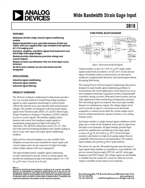
Wide Bandwidth Strain Gage Input3B18Rev. 0Information furnished by Analog Devices is believed to be accurate and reliable. However, no responsibility is assumed by Analog Devices for its use, nor for any infringements of patents or other rights of third parties that may result from its use. Specifications subject to change without notice. No license is granted by implication or otherwise under any patent or patent rights of Analog Devices. Trademarks and registered trademarks are the property of their respective companies.One Technology Way, P.O. Box 9106, Norwood, MA 02062-9106, U.S.A.Tel: 781.329.4700 Fax: 781.326.8703© 2004 Analog Devices, Inc. All rights reserved.FEATURESWideband (20 kHz) single-channel signal conditioning module.Module Bandwidth is user-selectable between 20 kHz and 100Hz, with user-supplied filter caps installed in the optional AC1310 ranging card.Interfaces, amplifies, and filters signals from balanced 4-arm full-bridge strain-gage bridges.Module provides simultaneous precision voltage and current outputs.Module circuitry can withstand 130v rms at the input screw-terminalsAll 3B18 series modules are mix-and-match and Hot SwappableAPPLICATIONSIndustrial signal conditioning Industrial signal isolation Industrial signal filteringPRODUCT OVERVIEWThe 3B Series of Signal Conditioning I/o Subsystems provide a low-cost, versatile method of transferring analog transducer signals to a data acquisition, monitoring or control system without the inherent noise, non-linearity, drift and extraneous voltages. The modules are designed to directly accept analog signals from Thermocouples, RTD’s, AC and DC Strain Gages, Torque Transducers, Frequency Transducers, LVDTs, millivolt or process current signals. The modules amplify, isolate, linearize and convert the transducer output signals to standardized analog inputs for high-level analog I/Osubsystems. The 3B Series Subsystem consists of a 10” relay rack with universal mounting backplane and a family of plug-in (up to 16 per rack) input and output signal conditioning modules.Eight and four channel backplanes are also available. Each backplane incorporates screw terminals for sensor inputs and current outputs and a 26-pin connector for high-level single-ended voltage outputs to the user’s equipment.The input modules feature complete signal conditioning circuitry optimized for specific sensors or analog signals and provide two simultaneous high-level analog outputs: 0 to +10V (or +10V) and 4-20 mA (or 0-20 mA).FUNCTIONAL BLOCK DIAGRAMFigure 1. 3B18 Functional Block DiagramOutput modules accept 0 to +10V (or +10V) single-ended signals and provide an isolated 4-20 mA (or 0-20 mA) process signal. All modules feature a universal pin-out and may bereadily hot-swapped under full power and interchanged without disrupting field wiring.The Analog Devices 3B Series Signal Conditioning Subsystem is designed to easily handle signal conditioning problems inmeasurement and control applications. Some typical uses are in microcomputer-based data acquisition systems, programmable controllers, analog recorders, dedicated control systems, and any other applications where monitoring of temperature, pressure, flow and analog signals are required. Since each input module features two simultaneous outputs, the voltage output can be used to provide an input to a microprocessor-based data acquisition or control system while the current output can be used for analog transmission, operator interface, or an analog backup system.Each input module is a single-channel signal conditioner which plugs into a socket on the backplane and accepts its signal from the input screw terminals. All input modules provide input protection, amplification and filtering of the input signal, accuracy of +0.1%, low drift of +1 uV/o C (low-level input modules), and feature two high-level analog outputs that are compatible with most process instrumentation. The isolated input modules also provide +1500 V peak isolation.The choice of a specific 3B module depends upon the type of input signal. Input modules are available to accept millivolt, volt, process current, thermocouple, RTD, AC and DC strain gage, frequency and LVDT inputs. The voltage output of each module is available from the system I/O connector while the current output is available on the output screw terminals.3B18Rev. 0 | Page 2 of 8GENERAL DESCRIPTIONThe 3B18 is a wideband (20kHz) single-channel signal conditioning module which interfaces, amplifies, and filters signals from balanced 4-arm full-bridge strain-gage bridges with a resistance from 100Ω to 10 k Ω, providing simultaneous precision voltage and current outputs. The module provides two user-selectable (via front-panel switches) bridge excitation voltages: +10 V for bridges with a load impedance down to 300W or +3.33V for 120W bridges or others below 300W . Module bandwidth is also user-selectable between 20 kHz and 100 Hz, with user-supplied filter capacitors installed in theoptional AC1310 ranging card. The 3B18 protects the computer side from damage due to field-side over-voltage faults up to 130V rms. In addition, the current output withstands 130V rms without damage and interfaces user equipment through screw terminals located on the 3B Series backplane. The 3B18 is a plug-in, mix-and-match, hot-swappable module which is easily field calibrated via front-panel zero and span adjustments for both voltage and current outputs.3B Series Custom-Ranging Program – Externally-programmable Model 3B18-00, enables the user to configure a special input range by using the optional plug-on AC1310ranging card, which houses user-supplied resistors to determine zero and span. To facilitate selecting resistors, a Windowsprogram, 3B-CUSTOM, calculates resistor values based on the user-desired input/output ranges.A chopper-stabilized low-drift (+1uV/o C) input amplifierassures long-term stability. For user convenience, the zero and span can be factory configured to meet custom range needs (Model 3B18-CUSTOM) or can be externally programmed (Model 3B18-00) via user supplied resistors inserted in the optional AC1310 plug-on ranging card...Figure 23B18Rev. 0 | Page 3 of 83B18 Models AvailableModel Input Bridge InputRange Excitation 1 Sensitivity Output Ranges3B18-00 Full Bridge Externally Programmable 3 +10.0 V or +3.33 V Externally Programmable 3 -10 V to +10 V & 0 mA to 20 mA 3B18-01 Full Bridge -30 mV to +30 mV +10.0 V or +3.33 V 3 mV/V @ 10 Vexc -10 V to +10 V & 0 mA to 20 mA 3B18-02 Full Bridge -10 mV to +10 mV+10.0 V or +3.33 V 3 mV/V @ 3.33 Vexc-10 V to +10 V & 0 mA to 20 mA3B18-CustomFull Bridge*+10.0 V or +3.33 V**1Output current range may be user programmed to 4 mA to 20 mA using jumper supplied. 2Requires AC1310 ranging card.* Custom Input/Output ranges are available. Refer to configuration guide.3B18 Specifications(typical @ +25°C and ±15 V dc, and +24 V dc Power)Description Model 3B18Input RangeStandard Range ±30 mV (3 mV/V sensitivity @ V exc = +10V) ±10 mV (3 mV/V sensitivity @ V exc = +3.33 V) Custom Ranges±5 mV to ±500 Output RangeVoltage (R L > 2 K Ω) -10 V to +10 VCurrent (R L = 0 to 850Ω)1 4 mA to 20 mA or 0 mA to 20 mA Maximum Current Output Span0 mA to 31 mAAccuracy 2Initial @ +25°C±0.1% SpanNonlinearity 2 ±0.01%Span Stability vs. TemperatureVoltage Output Zero ±3 µV/°C (RTI) Span ±25 ppm of Reading/°CCurrent Output 3 Zero ±25 ppm of Span/°C Span±25 ppm of Reading/°CBridge ExcitationVoltage user-selectable +10 V or +3.33 V Voltage, tolerance ±2% Voltage vs. Temperature±0.0015%/°CBridge Resistance RangeV exc = +10.0 V300 Ωto 1 k Ω3B18Rev. 0 | Page 4 of 8V exc = +3.33 V100 Ωto 10 k Ω Zero and Span Adjustment Range 4 ±5% of Span Input Bias Current +25 nA Input Resistance 100 M Ω Bandwidth, -3 dB20 kHz Output Rise Time, 10% to 90% Span24µsCommon-Mode Voltage (CMV)Input-to-Output, Continuous ±10 V peak, maximum TransientANSI/IEEE C37.90.1- 1989Common Mode Rejection (CMR)1 kSource Imbalance, 50/60 Hz100 dBInput Protection, Signal and Excitation VoltageContinuous130 V rms maximumTransient ANSI/IEEE C37.90.1-1989 Voltage Output Protection Continuous Short to Ground Current Output Protection130 V rms, continuousPower Supply Voltages 5±15 V dc Supplies Rated Operation ±(13.5 V dc to 16.5 V dc) Current +50 mA, -15 mA Sensitivity±0.01% span/V+24 V dc Loop Supply Rated Operation +12 V dc to +30 V dc Current +27 mA @ l out = 20 mA Sensitivity±0.0002% span/VMechanical Dimensions3.15" x 3.395" x 0.775"(80.0 mm x 86.2 mm x 19.7 mm) EnvironmentalTemperature Range Rated Performance -25°C to +85°C Storage-55°C to +85°CRelative Humidity, 24 hours 0 to 95% @ +60°C non-condensing RFI Susceptibility±0.5% Span error @ 400 MHz, 5 Watt, 3 ft1 For a 0 mA to 20 mA range, a typical minimum output current is 10 µA. 2Includes the combined effects of repeatability, hysteresis, and nonlinearity. 3With respect to the voltage output. 4A wide range of custom zero suppression and span is available with the 3B18-00 model, using the AC1310 ranging card. 5+24 V dc loop power is required for driving the current output at loads up to 850Ω. If a current output load of 400Ω or less is applied, +15 V dc is sufficient for loop power. If only voltage output is used, loop power is not required.3B18Rev. 0 | Page 5 of 8PIN CONFIGURATIONS AND FUNCTIONAL DESCRIPTIONSFigure 3 3B18 Input Field ConnectionsTable 1. Pin Function Descriptions—Pin No.Description 1 +EXC 2 HI 3 LO 4 -EXCFigure 4 . Model 3B Series Module, with pin-out assignments.ESD CAUTIONESD (electrostatic discharge) sensitive device. Electrostatic charges as high as 4000 V readily accumulate on the human body and test equipment and can discharge without detection. Although this product features proprietary ESD protection circuitry, permanent damage may occur on devices subjected to high energy electrostatic discharges.Therefore, proper ESD precautions are recommended to avoid performance degradation or loss of functionality.3B18Rev. 0 | Page 6 of 8OUTLINE DIMENSIONSFigure 5. Outline Dimensions3B18 NOTESRev. 0 | Page 7 of 83B18Rev. 0 | Page 8 of 8NOTES© 2004 Analog Devices, Inc. All rights reserved. Trademarks and registered trademarks are the property of their respective companies. D05091-0-9/04(0)。