OPTISWORKS软件 TV模组光学模拟
- 格式:pdf
- 大小:10.27 MB
- 文档页数:83
optsim手册【实用版】目录1.OptSim 手册概述2.OptSim 的功能和特点3.OptSim 的应用领域4.OptSim 的使用方法和技巧5.OptSim 的优点和局限性6.OptSim 的未来发展正文1.OptSim 手册概述OptSim 手册是一本介绍光学仿真软件 OptSim 的专业指南,旨在帮助用户更好地理解和使用该软件。
OptSim 是一款功能强大的光学设计与仿真软件,广泛应用于光学成像、照明系统、光通信等领域。
通过手册的详细讲解,用户可以熟练掌握 OptSim 的使用方法,进一步提高光学设计效率和精度。
2.OptSim 的功能和特点OptSim 具有以下主要功能和特点:(1)强大的光学元件库:OptSim 提供了丰富的光学元件库,包括球面镜、平面镜、透镜、光栅、光纤等,用户可以根据需求选择合适的元件进行光学设计。
(2)灵活的光学系统构建:用户可以自由地添加、删除和修改光学元件,构建复杂的光学系统。
(3)多物理光学仿真:OptSim 采用多物理光学仿真技术,可以模拟多种光学现象,如光的折射、反射、干涉等。
(4)高效的优化算法:OptSim 内置了多种优化算法,可以帮助用户快速找到满足特定性能指标的光学设计方案。
(5)丰富的后处理功能:OptSim 支持多种后处理功能,如光学系统的像差分析、波前传感器分析等,可以帮助用户全面了解光学设计的性能。
3.OptSim 的应用领域OptSim 在以下领域有广泛的应用:(1)光学成像:OptSim 可以模拟各种成像系统,如望远镜、显微镜、摄像头等,帮助用户提高成像质量。
(2)照明系统:OptSim 可以模拟各种照明系统,如 LED 灯具、路灯等,帮助用户优化照明效果。
(3)光通信:OptSim 可以模拟光通信系统,如光纤通信、光波分复用等,帮助用户提高通信速率和传输距离。
(4)光学制造:OptSim 可以模拟光学制造过程,如光学元件的加工、光学系统的装配等,帮助用户提高生产效率和质量。
光学模组知识点总结光学模组是一个涵盖了光学元件、光学设计、光学加工、光电传感、光电信号处理、光电系统集成等多个方面知识的综合性领域。
在高科技领域中,光学模组应用广泛,涉及到光通信、光学显微镜、摄影镜头、激光雷达、激光加工等多个领域。
光学模组的知识点非常丰富,本文将对光学模组相关的知识点进行总结。
一、光学元件1.透镜透镜是光学系统中最基本的元件,根据其曲率可以分为凸透镜和凹透镜。
透镜的焦距和倍率是透镜最基本的参数,可以通过透镜的焦距计算出像距、物距和像高等参数。
2.棱镜棱镜是将光线折射、反射、漫射的光学元件,可以将白光分散成不同的波长光谱,也可以进行全反射和漫反射。
3.反射镜反射镜是一种通过反射来调整光线方向的光学元件,包括平面反射镜、球面镜、椭圆面镜等。
反射镜在望远镜、激光器等光学系统中广泛应用。
4.偏振片偏振片是可以选择特定方向光线通过的光学元件,可以将自然光变成偏振光,也可以将偏振光转换为自然光。
5.滤光片滤光片可以选择性地透过一定波长的光,也可以选择性地吸收或反射一定波长的光。
6.衍射光栅衍射光栅是一种可以通过衍射作用进行光谱分析的光学元件,通常用于分光仪、光谱仪等光学系统。
7.光学薄膜光学薄膜是一种可以改变光通过特定波长的透射率、反射率的光学元件,广泛应用于镜片、滤光片、透镜等光学元件。
8.光学元件的表面处理光学元件的表面处理包括抛光、镀膜、防刮花、防反射等工艺,是保证光学元件质量的关键。
二、光学设计1.光学系统的设计原理光学系统的设计原理主要包括光线追迹、光束传输、光学系统的布局、颗粒光学等多个方面的知识。
2.光学系统的优化光学系统的优化包括了光学系统的结构优化、元件参数的优化、光学系统的工作模式优化等多个方面的内容。
3.光学系统的仿真光学系统的仿真是借助计算机进行光学系统的模拟和分析,可以通过仿真对光学系统进行性能评估和改进。
4.光学系统的成像原理光学系统的成像原理是光学设计的核心内容,包括了像差、色差、成像质量、分辨率、变视角等多个方面的知识。

光机光学模组-概述说明以及解释1.引言1.1 概述:光机光学模组是一种集成了光学元件和机械部件的模块化设备,用于实现光学系统的功能。
随着现代科学技术的不断发展,光学技术在工业和科学研究领域起着越来越重要的作用。
光机光学模组作为光学技术的重要应用形式,具有高度集成、可靠性高、易于搭建和调试等优点,被广泛应用于光通信、光测量、激光加工等领域。
本文将从光机光学模组的定义、应用和特点等方面进行讨论,旨在深入探讨光机光学模组在光学系统中的作用和优势,为读者提供更加全面的了解和认识。
通过对光机光学模组的研究,我们可以更好地推动光学技术的发展,实现对光学系统性能的进一步优化和提升。
1.2 文章结构文章结构部分应包括对整篇文章的框架和内容安排的介绍,具体可以包括以下内容:文章结构部分介绍了本文的整体框架和各个部分的内容安排。
本文分为引言、正文和结论三个部分。
- 引言部分主要是对光机光学模组进行概述,介绍其在光学领域的重要性和应用前景。
- 正文部分将详细探讨光机光学模组的定义、应用和特点,通过介绍其原理、组成结构和工作原理,使读者对光机光学模组有更深入的了解。
- 结论部分对全文进行总结,简要概括了文章的主要内容和结论,并展望了未来光机光学模组的发展方向和趋势。
文章结构部分的介绍有助于读者更好地理解全文内容的组织和安排,提高文章的可读性和逻辑性。
1.3 目的:本文的目的在于介绍光机光学模组的相关知识和应用,旨在帮助读者深入了解这一领域的技术和发展趋势。
通过对光机光学模组的定义、应用和特点进行详细分析,读者可以更全面地了解光学模组在光学系统中的重要性和作用。
同时,本文也将探讨光机光学模组在未来的发展方向,展望其在光学技术领域的前景。
希望通过本文的介绍,读者可以对光机光学模组有一个更清晰的认识,从而为相关研究和应用提供参考和指导。
2.正文2.1 光机光学模组的定义光机光学模组是一种集成了光学元件和机械结构的模组,其主要作用是将光学元件进行组合、封装和保护,以便更方便地应用于光学系统中。
光学设计软件介绍光学设计软件是一种用于设计、模拟和优化光学系统的专业软件。
它能够帮助光学工程师在设计过程中进行复杂的光学分析和计算,以实现更好的系统性能和结果。
在本文中,我将介绍几款常用的光学设计软件,并分别对它们的特点和应用领域进行详细介绍。
首先,我们来介绍一款被广泛应用的商业光学设计软件,Zemax。
Zemax是一款集成了光学设计工具、分析和优化功能的软件。
它提供了丰富的光学元件和材料库,用户可以通过拖放功能轻松搭建光学系统,并实时进行光束跟踪和模拟。
Zemax具有强大的快速优化功能,能够自动优化光学系统的参数,极大地提高了光学系统的设计效率。
此外,Zemax还提供了光学系统的散射和散射分布模拟功能,可用于高级光学分析和设计。
Zemax广泛应用于光学器件、成像系统、激光系统等领域。
另一款值得关注的光学设计软件是CODEV。
CODEV是光学工程师和设计师们非常喜欢使用的一款商业软件。
它提供了先进的面片拟合分析算法,可以模拟光学表面的形状和光线传输。
CODEV具有非常强大的工程优化功能,可以自动找到最优的光学系统参数,以满足特定的设计需求。
该软件还支持干涉仪的设计和分析,能够帮助用户进行光波前传播分析和高级光学性能计算。
CODEV广泛应用于天文望远镜、光纤通信和半导体设备等领域。
另外,我们还有一款开源软件,OpenFST。
OpenFST是一种用于模拟和优化光学系统的自由软件。
它具有高性能和高效的光束跟踪算法,能够精确模拟光线的传输和变换。
OpenFST还支持多种优化算法,可以自动最佳的光学参数。
此外,它还提供了基于几何和波动原理的分析工具,可用于高级光学模拟和计算。
OpenFST广泛应用于光学设备、光纤通信和太阳能电池等领域。
综上所述,光学设计软件在现代光学工程中起着重要的作用。
由于不同软件具有不同的优势和特点,适合不同领域和需求的光学设计。
通过选择适合的软件,光学工程师能够更加高效、准确地进行光学系统设计和优化,从而实现更好的技术和应用效果。
Lighttools光学仿真软件-含核心模块(Core Module)、照明模块(Illumination Module)、优化模块(Optimization Module)、高级物理模块(Advanced Physics Module)和数据交换模块(Data Exchange Module)各模块性能:(1)核心模块:为所有模块的工作基础。
提供图形化的三维实体建模功能和交互式光线追迹,用于创建可视化的光学和光机一体化系统包括定义材料和光学表面属性的功能。
具备指导功能的用户界面、中英文界面的自由选用、面向任务和应用的各类数据库、专用工具箱和设计系统实例、可扩展编程的自动化流程以及机械模型的照片级渲染;(2)照明模块:分析和模拟光通过模型中的光学和机械部件后的情况。
可描述多个光源和接收面,使用蒙特卡罗快速追迹光线,提供经过模型之后的强度、亮度、照度的精确预测。
照明分析功能可现实光源在模型中的发光效果;(3)优化模块:可自动提高各种照明系统的性能。
可人已从多种系统参数中选择优化变量,确定边界条件和评价函数以获得需要的系统性能指标可确保在很短时间内获得实用解决方案;(4)高级物理模块:拓展了高端应用的光学模拟功能。
可充分利用编程扩展的优势来开发、定制新型光学元件和照明子系统,如复印机、扫描仪、偏振元件、散射片、膜系、包括渐变折射率在内的特殊光学材料等。
结果可打包成方便小巧格式,与他人共享。
可创建磷粉发光材料;(5)数据交换模块:提供符合工业标准的CAD文件输入和输出功能,包括各自独立的IGES、STEP、SAT、CATIA_V4、V5和Parasolid格式的数据交换模块。
同时支持对导入几何体的结组、简化、修复功能,以维持CAD模型的完整性和提高光线的追迹速度。
可实现功能(1)交互式(point-and-shoot)光线追迹可以快速检验系统模型;(2)优化功能,可自动提高系统性能;(3)系统模型构建,包括偏振、散射、表面反射、折射与衍射、镀膜和彩色滤光片等特性;(4)支持各类表面光学属性,包括彩色和半透明光学塑料和玻璃、毛面和亚光表面涂料、光学镀膜和滤光片;(5)复杂光学表面和元件建模;(6)全系列光源模型;(7)接收面滤片功能;(8)支持基于测量的光线数据库光源,包括Radiant Source TM光源模型;(9)使用测试(BSDF)散射数据模拟散射效果;(10)自带建模库、光源库、表面涂饰库、镀膜库、滤色片库和面向应用的工具库;(11)交互式智能化的用户界面;(12)支持Visual Basic宏定制解决方案;(13)与CAD软件协同工作。
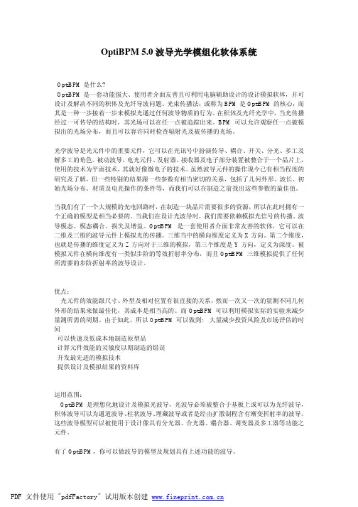
OptiBPM 5.0波导光学模组化软体系统OptiBPM是什么?OptiBPM是一套功能强大、使用者介面友善且可利用电脑辅助设计的设计模拟软体,并可设计及解决不同的积体及光纤导波问题。
光束传播法,或称为BPM是OptiBPM的核心,而其是一种一步接着一步来模拟光通过任何波导物质的行为。
在积体及光纤光学中,当光传播经过一可传导的结构时,其光场可以在任一点被追踪出来。
BPM可以允许观察任一点被模拟出的光场分布,而且可以容许同时检查辐射光及被传播的光场。
光学波导是光元件中的重要元件,它可以在光讯号中扮演传导、耦合、开关、分光、多工及解多工的角色。
被动波导、电光元件、发射器、接收器及电子部分装置被整合于一个晶片上,使用的技术为平面技术,其就好像微电子的技术。
虽然波导元件的操作现今已有相当程度的研究及了解,但一些特别的结果跟一些参数有相当密切的关系,包括了几何外形、波长、初始光场分布、材质及电光操作的条件等,而我们可以在制造之前找出这些参数的最佳值。
当我们有了一个大规模的光电回路时,在制造一块晶片需要很多的资源,所以在此时拥有一个正确的模型是相当必要的。
当我们在设计光波导时,我们需要依赖模拟光信号的传播、波导模态、模态耦合、损失及增益。
OptiBPM是一套使用者介面非常友善的软体,它可以在二维及三维旳波导元件上模拟光的传播。
三维当中的横向维度定义为X方向。
第二个维度,也就是传播的维度定义为Z方向对于三维的模拟,第三个维度是Y方向,定义为深度。
被模拟元件在横向维度有一类似步阶的等效折射率分布,而且OptiBPM三维模拟提供了任何所需要的步阶折射率的波导设计。
优点:光元件的效能跟尺寸、外型及相对位置有很直接的关系,然而一次又一次的量测不同几何外形的结果来做最佳化,其成本是相当高的。
而OptiBPM可以利用模拟实际的实验来减少量测所需的周期。
由于如此,所以OptiBPM可以做到: 大量减少投资风险及市场评估的时间可以快速及低成本地制造原型品计算元件效能的灵敏度以期制造的错误开发最先进的模拟技术提供设计及模拟结果的资料库运用范围:OptiBPM是理想化地设计及模拟光波导,光波导必须被整合于基板上或可以为光纤波导,积体波导可以为通道波导、柱状波导、埋藏波导或者是经由扩散制程含有渐变折射率的波导。
OptiSystem 7入门讲义(中文)此讲义仅适用于OptiSystem光通信仿真软件的初学者。
第一课软件操作入门(Getting started)(上)Optisystem 光通信仿真软件简识OptiSystem (光通信系统设计软件),什么是Optisystem?光通讯系统正在变得日益复杂。
这些系统通常包含多个信号通道、不同的拓扑结构、非线性器件和非高斯噪声源,对们的设计和分析是相当的复杂和需要高强度劳动的。
先进的软件工具使得这些系统的设计和分析变得迅速而有效。
OptiSystem是一款创新的光通讯系统模拟软件包,它集设计、测试和优化各种类型宽带光网络物理层的虚拟光连接等功能于一身,从长距离通讯系统到LANS和MANS都适用。
一个基于实际光纤通讯系统模型的系统级模拟器,OptiSystem 具有强大的模拟环境和真实的器件和系统的分级定义。
它的性能可以通过附加的用户器件库和完整的界面进行扩展,而成为一系列广泛使用的工具。
全面的图形用户界面控制光子器件设计、器件模型和演示。
巨大的有源和无源器件的库包括实际的、波长相关的参数。
参数的扫描和优化允许用户研究特定的器件技术参数对系统性能的影响。
因为是为了符合系统设计者、光通讯工程师、研究人员和学术界的要求而设计的,OptiSystem 满足了急速发展的光子市场对一个强有力而易于使用的光系统设计工具的需求。
优点·投资风险大幅度降低,快速投入市场·快速、低成本的原型设计·系统性能的全面认识·辅助设计容差参数的参数灵敏性评估·面向用户的直观的设计选项和脚本·直接存取大规模的系统特征数据·自动的参数扫描和优化应用OptiSystem允许对物理层任何类型的虚拟光连接和宽带光网络的分析,从远距离通讯到MANS和LANS都适用。
它的广泛应用包括: 物理层的器件级到系统级的光通讯系统设计·CATV或者TDM⁄WDM网络设计·SONET⁄SDH的环形设计,Radio over Fiber系统,自由空间光通信系统(FSO)·传输器、信道、放大器和接收器的设计·色散图设计·不同接受模式下误码率(BER)和系统代价(penalty)的评估·放大的系统BER和连接预算计算主要特点.1.器件库为了完全发挥效率,器件模块应该再现真实器件的实际的性能,确定由于选择精度和效率引起的影响。

ISSN1672— 4305CN12—1352/N 实验室科学LABO R ATO R YSCIENCE 第18 卷第 1 期2015 年 2 月Vol. 18No.仆eb. 2015OptiSystem仿真在光纤通信实验教学中的应用王秋光,张亚林,胡彩云,赵莹琦(广州大学松田学院电气与汽车工程系,广东广州511370摘要:介绍了光纤通信实验教学中的光纤色散实验、激光器调制频率特性实验、掺铒光纤放大器实验、光接收机实验与WDM系统实验5个OptiSystem仿真实验,给出了每个实验项目的仿真模型及模型中的参数设置,简要分析了仿真实验结果。
OptiSystem仿真实验可以反复观察练习,节省较高的实验费用,有利于学生对光纤通信课程教学中抽象的理论知识的理解,在光纤通信实验教学中取得了较好效果。
关键词:OptiSystem ;光纤通信;仿真;实验教学中图分类号:TN929. 11; TP391. 9 文献标识码:Adoi :10. 3969/j. issn. 1672—4305. 2015. 01. 008Application of OptiSystem simulation in experimentteach ing of optical fiber com muni cati onWANG Qiu —gua ng, ZHANG Ya —lin , HU Cai —yun , ZHAO Ying —qi(Departme nt of Electrical & Automotive Engin eeri ng , Guan gzhou Un iversitySon tian College , Gua ng-zhou 511370, ChinaAbstract :Introduces five OptiSystem simulation experiments , such as the fiber dispersi on experi-me nt , modulatio n freque ncy characteristics of the laser , erbium doped fiber amplifier , optical receiver experiment and WDM experiment , simulation model and model parameters sett ings of each experime n-tal item and a brief an alysis of the simulation results are given OptiSystem simulation can be repeated-ly observed in practice , save high experime ntal cost , and con ducive to the stude nts on the course of optical fiber com muni cati ons to un dersta nd abstract theoretical kno wledge , have achieved good results in the experime ntal teach ing of optical fiber com muni cationKey words :OptiSystem ; optical fiber com muni catio ns ; simulatio n ; experime ntal teaching基金项目:广州大学松田学院院级特色专业建设项目。
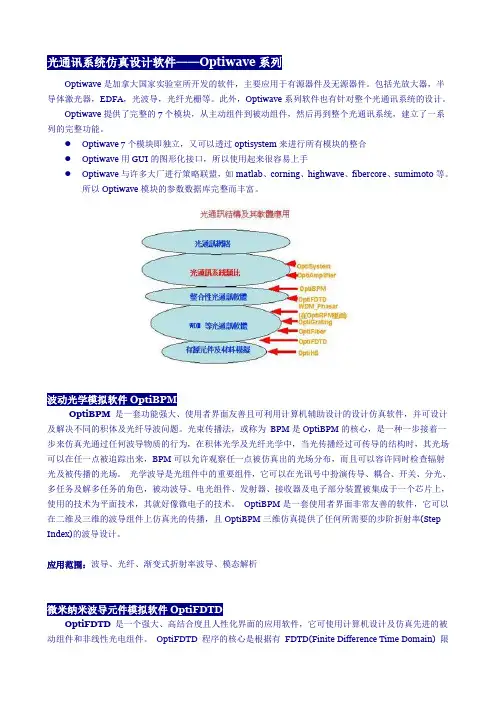
光通讯系统仿真设计软件——Optiwave系列Optiwave是加拿大国家实验室所开发的软件,主要应用于有源器件及无源器件。
包括光放大器,半导体激光器,EDFA,光波导,光纤光栅等。
此外,Optiwave系列软件也有针对整个光通讯系统的设计。
Optiwave提供了完整的7个模块,从主动组件到被动组件,然后再到整个光通讯系统,建立了一系列的完整功能。
●Optiwave 7个模块即独立,又可以透过optisystem来进行所有模块的整合●Optiwave用GUI的图形化接口,所以使用起来很容易上手●Optiwave与许多大厂进行策略联盟,如matlab、corning、highwave、fibercore、sumimoto等。
所以Optiwave模块的参数数据库完整而丰富。
波动光学模拟软件OptiBPMOptiBPM 是一套功能强大、使用者界面友善且可利用计算机辅助设计的设计仿真软件,并可设计及解决不同的积体及光纤导波问题。
光束传播法,或称为BPM是OptiBPM的核心,是一种一步接着一步来仿真光通过任何波导物质的行为,在积体光学及光纤光学中,当光传播经过可传导的结构时,其光场可以在任一点被追踪出来,BPM可以允许观察任一点被仿真出的光场分布,而且可以容许同时检查辐射光及被传播的光场。
光学波导是光组件中的重要组件,它可以在光讯号中扮演传导、耦合、开关、分光、多任务及解多任务的角色,被动波导、电光组件、发射器、接收器及电子部分装置被集成于一个芯片上,使用的技术为平面技术,其就好像微电子的技术。
OptiBPM是一套使用者界面非常友善的软件,它可以在二维及三维的波导组件上仿真光的传播,且OptiBPM三维仿真提供了任何所需要的步阶折射率(Step Index)的波导设计。
应用范围:波导、光纤、渐变式折射率波导、模态解析微米纳米波导元件模拟软件OptiFDTDOptiFDTD是一个强大、高结合度且人性化界面的应用软件,它可使用计算机设计及仿真先进的被动组件和非线性光电组件。
PRODUCT FEATURES
扩展了 CODE V 和 LightTools 的互操作性 CODE V 和 LightTools 之间改进互操作性的功能,可以使设计者易于模
拟包含成像和非成像元件的光学系统,并节省开发时间。
CODE V 基于表面的模型能够在 LightTools 中自动转换为高保真度的实体模型,用于光学产品仿真。
产品之间的设计更新实现无缝保持,作用范围包括所有光学属性、接收器和光源。
基于表面的建模 LightTools 中基于表面的建模允许将导入的几何体作为独立的曲面及几何实体的一部分进行光线追迹,以实现更高效与更灵活的光学系统仿
真。
新的建模和光线追迹功能对 AR/VR 头戴式设备、 LiDAR、车用摄像
头以及头戴显示产品中的照明元件设计尤其实用。
仿真功能的增强 为 AR/VR 头戴式显示设备以及LiDAR 光学系统提供额外支持的增强仿真功能包括: •光源建模的改进:例如新的定位选项和切趾分布、在配置和优化中使用单色光源光谱类型,以及设置光源偏振的功能•
光程长度分析可用于反向光线追迹•
相干模拟可使用多波长光源并可导出复数场数据•光栅可进行衍射效率的计算
全新模块:SmartStart 资料库 利用 LightTools SmartStart 资料库可以设计出具有极致物理真实感的虚拟样机,该数据库提供广泛的测量材料数据及光学属性数据。
借助
SmartStart 资料库中的资源,设计者可以快速地决定光学系统中使用的
材料,用以优化产品性能并节约成本。
LightTools 2022.03 版本更新亮点 提升您的照明光学设计。
光學設計 OPTIS OptisWorks Studio v2007中文名稱:光學設計英文名稱:OPTIS OptisWorks Studio v2007資源類型:ISO發行時間:2007年製作發行:OPTIS地區:美國語言:英語簡介:下載鏈結來自SHARETHEFILE,未經過安裝測試與安全檢測,使用者後果自負與本論壇無關軟體版權歸原作者及其公司所有,如果你喜歡,請購買正版支持正版著名的光學系統開發公司OPTIS最新發新的強大光學仿真利器:OPTIS OptisWorks Studio 2007,OPTISWORKS是OPTIS公司開發的系統做成光學軟體,他集成成SOLIDWORK工作環境下,利於設計與光學分析為一體進行工作。
這是一個非常優秀的光機設計仿真軟體,支援Windows 32位元以及x64位元作業系統!!在歐洲和日本都是廣泛應用的軟體!OPTIS 創立於 1989 年,長久以來在傳統光學、汽車業、航空業、國防工業、照明產業或消費者電子業等領域中,始終是業界提升光學系統設計生產力的最佳選擇。
OPTIS 目前在全球各地為超過 500 家重要客戶提供眾多類型的服務,主要據點在歐洲、美國及日本地區,客戶群則涵括 Thomson 、Alcatel 、Ericsson 、 Sony 、JVC 、Nikon 、Sharp、Samsung 、 Matsushita 、Jordan 、Nasa 等世界知名企業。
OPTIS OptisWorks Studio 2007 設計 - 分析 - 最佳化你的照明系統OPTIS OptisWorks Studio 應用範圍解決方案:汽車業 - 電子業 - 消費者產品 - 照明 - 光學設計 - 雷射路徑 OPTISWORKS 提供你下列產品的解決方案: 發光按鈕 光學滑鼠 顯示儀器 CD 雷射讀取頭 搖控設備 交通號志 影印機 投影機 條碼讀取機 燈具 車頭燈 車尾燈 儀錶板 發光的玩具 爐具與冰箱內部燈具 掃瞄機 個人數位助理 手錶 相機 輸入裝置 …等。
OptiSystem 仿真软件模型案例目录1光发送机(Optical T ransmitters)设计1.1光发送机简介1.2光发送机设计模型案例:铌酸锂(LiNbO3)型Mach-Zehnder调制器的啁啾(Chirp)分析2光接收机(Optical Receivers)设计2.1光接收机简介2.2光接收机设计模型案例:PIN光电二极管的噪声分析3光纤(Optical Fiber)系统设计3.1光纤简介3.2光纤设计模型案例:自相位调制(SPM)导致脉冲展宽分析4光放大器(Optical Amplifiers)设计4.1光放大器简介4.2光放大器设计模型案例:EDFA的增益优化5光波分复用系统(WDM Systems)设计5.1光波分复用系统简介5.2光波分复用系统使用OptiSystem设计模型案例:阵列波导光栅波分复用器(A WG )的设计分析6光波系统(Lightwave Systems)设计6.1 光波系统简介6.2 光波系统使用OptiSystem设计模型案例:40G单模光纤的单信道传输系统设计7色散补偿(Dispersion Compensation)设计8.1 色散简介8.2 色散补偿模型设计案例:使用理想色散补偿元件的色散补偿分析8孤子和孤子系统(Soliton Systems)9.1 孤子和孤子系统简介9.2 孤子系统模型设计案例:9结语1 光发送机(Optical Transmitters )设计1.1 光发送机简介一个基本的光通讯系统主要由三个部分构成,如下图1.1所示:作为一个完整的光通讯系统,光发送机是它的一个重要组成部分,它的作用是将电信号转变为光信号,并有效地把光信号送入传输光纤。
光发送机的核心是光源及其驱动电路。
现在广泛应用的有两种半导体光源:发光二级管(LED )和激光二级管(LD )。
其中LED 输出的是非相干光,频谱宽,入纤功率小,调制速率低;而LD 是相干光输出,频谱窄,入纤功率大、调制速率高。
常见光学仿真设计软件光学仿真设计软件是指通过计算机模拟光学系统的光学性能和传输特性,帮助设计师优化光学系统设计的工具。
以下是一些常见的光学仿真设计软件。
1.ZEMAX:ZEMAX是一款功能强大的光学设计软件,用于设计复杂的光学系统。
它提供了完整的光学设计和分析工具,包括光束追迹、像差分析、光学优化等功能。
ZEMAX还具有友好的图形用户界面和丰富的光学库,方便用户快速建立和优化光学系统。
2.CODEV:CODEV是光学设计和分析软件的行业标准。
它提供了广泛的功能,包括光束追迹、像差分析、优化、散射分析等。
CODEV还具有强大的排版功能,可以生成专业的光学设计报告和文档,并支持与其他软件的集成。
3. TracePro:TracePro是一款全面的光学设计和分析软件,主要用于照明和显示系统的设计。
它具有强大的光线追迹和散射分析功能,并支持多种光学材料和纹理的模拟。
TracePro还具有直观的用户界面和先进的优化算法,方便用户进行系统优化和性能评估。
4.FRED:FRED是一款广泛使用的光学系统设计和分析软件,可用于设计各种类型的光学系统,包括光学投影仪、显微镜、望远镜等。
FRED提供了强大的光束追迹和像差分析工具,并具有直观的图形用户界面和丰富的资源库,方便用户进行系统模拟和优化。
5. ASAP:ASAP(Advanced Systems Analysis Program)是一款专门用于光学系统设计和光学材料研究的软件。
它提供了完整的光线追迹和像差分析功能,并支持多种计算方法和优化算法。
ASAP还具有强大的散射分析和材料模拟功能,可用于研究各种材料的光学性能。
6. LightTools:LightTools是一款功能强大的光学系统设计和优化软件,主要用于照明和光学显示系统的设计。
它提供了广泛的光束追迹和像差分析工具,并支持光能损耗和光学材料的模拟。
LightTools还具有直观的用户界面和灵活的优化算法,方便用户进行系统设计和性能评估。
OptisWorks Laser Propagation 2011 SP1Table Of ContentsOptisWorks Toolbars (1)Toolbar available for a part (1)The "OptisWorks Optical properties" toolbar (1)Toolbars available for part and assembly (2)The "OptisWorks Editors" toolbar (2)The "OptisWorks Optical design and Laser" toolbar (2)The "OptisWorks Viewers" toolbar (3)The "OptisWorks Tools" toolbar (3)Toolbars available for assembly (3)The "OptisWorks Detectors" toolbar (4)The "OptisWorks Ray tracing" toolbar (4)The "OptisWorks Simulation" toolbar (5)The "OptisWorks additional features" toolbar (5)The "OptisWorks 3D view" toolbar (5)OptisWorks Menus (6)OptisWorks menus for a part (6)Main menu (6)Menus specific for a part (6)OptisWorks menus for common for part and assembly (6)OptisWorks menus for an assembly (8)Main menu (8)Menus specific for an assembly (8)OptisWorks feature manager (11)OptisWorks feature manager for a part (11)OptisWorks feature manager for an assembly (11)Assembly (12)Simulations (12)Light Expert (13)Result manager (13)Optimization / tolerancing Parameters (13)Preferences (14)Part preferences (14)"Default Optical Properties" (15)Table Of Contents"Geometry precision of the tesselation" (16)"Anisotropy axis" (16)"Assembly preferences" located in the "Simulations" tree (17)Simulation parameters (17)Direct simulation (20)Inverse simulation (20)Interactive simulation (20)Library path (20)Getting Started Laser Propagation (24)Step 1 : Opening the project (25)Step 2 : Defining optical sequence (26)Step 3 : Creating Laser source (29)Step 4 : Performing Laser propagation and analysis (32)Step 5 : Modifying the geometry of your system (36)Step 6 : Updating Gaussian propagation (43)Creating a Laser Propagation System (44)Laser Propagation System (45)Laser Sources (45)Description (45)How to define a laser source (45)Type of source (47)Optical sequences (54)Sequence detection (54)The 3D sketch (58)Ray Tracing with a Laser Source (60)How to create a ray tracing with a Laser Source? (60)Ray tracing ON (60)Calculation (62)Laser Calculation (62)Performance (66)Multi-threading within OptisWorks (66)Check that Multithreading is running (67)Without multithreading: Number of threads = 1 (67)With multithreading: Number of threads = 4 (67)Files Management Recommendations (69)OptisWorks 2011 SP1 - Laser Propagation User GuideOther questions (70)Luminance simulation with XMP Map Post-processing: (70)What are the used vocabulary for photometry and radiometry units? (71)What is the version of the SolidWorks files used in OptisWorks Studio projects? (71)Known Problems (72)Known Problem (72)Bypass (72)Sources (72)Optical Properties (72)Detectors (73)Simulations (73)Ray tracing (74)Multi-configuration (74)Automation (74)Miscellaneous (74)Set up (77)Documentation (77)Limitations (77)Limitations (77)Sources (77)LCD Component (77)Detectors (78)Simulation (78)Miscellaneous (78)Optical Design and Laser Propagation (78)GRAPHIC USER INTERFACEOptisWorks ToolbarsThis page shows all OptisWorks toolbars available.The OptisWorks graphic user interface is composed of toolbars, menus and anOptisWorks feature manager.To be sure to see all of those, check if they are all toolbars enable in the "View\Toolbars"menu.Toolbars are displayed belong to if a part or an assembly is opened. When opening a part these toolbars are displayed.Toolbar available for a partThe "OptisWorks Optical properties" toolbaro This toolbar is used:o To set the surface quality.OptisWorks 2011 SP1 - Laser Propagation User Guideo To set the internal and external material.o To define ray file source.o To define a geometry as a surface source.o To define a geometry as a thermic surface source.o To define a geometry as a thermic volume source.o To manage the sources.o To define the preferences for the part.o To display and update the tessellation used by the simulation for the part."Tessellation": If one part is selected the "Tessellation" icon from the "Simulation"toolbar is disabled and the "Tessellation" icon from the "Optical Properties" toolbar displays the tessellation of the part selected. Otherwise the "Tessellation" icon of the "OpticalProperties" toolbar is disabled and the "Tessellation" icon of the "Simulation" toolbardisplays the tessellation of the assembly.Toolbars available for part and assemblyThe "OptisWorks Editors" toolbaro This toolbar is used:o To create a new surface quality.o To define different surface quality.o To create a new material.o To run the Glass Map Viewer.o To create a new spectrum definition.The "OptisWorks Optical design and Laser" toolbaro This toolbar is used:o To create a new lens.o To import an optical system.o To define an optical source.Graphic User Interfaceo To detect an optical sequence automatically.o To calculate different parameter of the optical system.o To generate the 3D sketch.o To define a laser source.o For laser and Gaussian propagation.The "OptisWorks Viewers" toolbaro This toolbar is used:o To run different OPTIS Labs.o To display the OPTIS Labs Online Help.The "OptisWorks Tools" toolbar"Customer Portal""Online Library""Online Upgrade""OptisWorks Homepage""License Portal""Online Support"Toolbars available for assemblyWhen opening an assembly these toolbars are displayed.OptisWorks 2011 SP1 - Laser Propagation User GuideThe "OptisWorks Detectors" toolbaro This toolbar is used:o To define illuminance, rays map and luminance detectors.o To define an intensity detector and a polar intensity detector.o To edit faces involved in the Surface contribution analyzer.o To edit faces included in the 3D Map detector.o To define a 3D Energy Density detector.The "OptisWorks Ray tracing" toolbaro This toolbar is used:o To toggle between photometric or interactive sources.o To define an interactive source for the ray tracing.o To show, hide, update the ray tracing.o To edit the ray tracing filtering with required or rejected faces.Graphic User Interface The "OptisWorks Simulation" toolbaro This toolbar is used:o To run a direct or inverse simulation.o To run an optimization or a tolerancing.o To run a multi configuration simulation.o To run a ray file post-processing for XMP map or for Intensity distribution.o To hide or display the simulation progress bar and to stop the simulation for multi-threading management.o To set the simulation priority above or below normal.The "OptisWorks additional features" toolbaro This toolbar is used:o To create a new LCD Component.o To create a new Ambient source.o To create a new Display source.o To export pattern definition for 3D texture.o To create a new 3D texture.The "OptisWorks 3D view" toolbaro This toolbar is used:o To hide/show XMP results in the 3D view.o To hide/show XM3 results in the 3D view.o To update and display the tessellation used by the simulation for this assembly.OptisWorks 2011 SP1 - Laser Propagation User GuideOptisWorks MenusThis page shows all OptisWorks menus available. To be able to see them, select the "OptisWorks" menu.The OptisWorks graphic user interface is composed of toolbars, menus and anOptisWorks feature manager.Menus are different belong if a part or an assembly is opened.OptisWorks menus for a partOpening a part, this is OptisWorks menu available.Main menuMenus specific for a partOptical designPart preferencesOptisWorks menus for common for part and assemblyNew optical properties definitionOptical properties settingsAdditional features3D viewOPTIS LabsToolsOptisWorks menus for an assembly Main menuMenus specific for an assemblyDetectors definitionRay tracingSimulationsOptical design3D TextureLCD componentOptisWorks feature managerThis page shows how is configured the OptisWorks feature manager.The OptisWorks graphic user interface is composed of toolbars, menus and anOptisWorks feature manager.The OptisWorks feature manager is an additional panel to the others from SolidWorks.This panel is different for a part or for an assembly.OptisWorks feature manager for a partThe OptisWorks feature manager for a part allows you to open surface quality,materials, sources and optical surfaces.OptisWorks feature manager for an assemblyThe OptisWorks feature manager for an assembly is composed of four parts:AssemblyA list of all Optical Properties: 3D Textures, LCD Component, Surface Quality, Material, Sources, Optical Surfaces, Detectors, Optical Systems and Default part preferences.For the Optical Design and Laser packages the definition of the optical systems is also available. This part also includes the preferences of all SolidWorks parts included in the assembly.SimulationsA list for the Simulations: Simulation parameters, Direct simulation, Inverse simulationand Interactive simulation.Light ExpertA list for the Light Expert: Light Path Finder, Ray Tracing Filtering and Surface Contribution Analyzer.Result managerA list of results provided by the simulations (OptisWorks result manager): Photometric results, Optical results, Laser results, Tolerancing / Optimization results, Interactive simulation results.Optimization / tolerancing ParametersThe list of Optimization and Tolerancing parameters: Optimization / Tolerancing Parameters and Targets, Tolerancing and Optimization.PreferencesThis page describes the preferences.You can define some preferences which are stored in each assembly or part file.o In the part you can define the tessellation and the default optical properties.o In the assembly you can define the simulation and results preferences.Part preferencesYou can edit the part preferences directly in the part with the "Preferences" icon.You can also select a part in the folder "Default part preferences" of the OptisWorks features manager then select the "Preferences" icon.The "Part preferences" panel is available with the "Part preferences" icon available in the "OptisWorks Optical properties" toolbar.The panel is also available by right clicking on "Part preferences" in the OPTIS tree of a part.When no files are opened it is also possible to check the "Default Part OpticalPreferences" from the "OptisWorks" menu."Default Optical Properties""Default Optical Properties" allows you defining the default surface quality and materials of your system.The "Glass" button allows you to switch from starting the glass catalogue viewer:"Geometry precision of the tesselation""Geometry precision of the tesselation" allows you defining the geometry precision for the calculation kernel.Max facet width (mm)The first option corresponds to a maximum for the length of the facets edges of the tessellation.The use of "Max facet width" should be done with precaution. If you try to use a small value for this parameter with an assembly of a large size this could generate a large tessellation and your computer should have not enough memory. For example 1 millimeter for this parameter is not appropriate with an assembly of about 1 meter.Deflection (mm)The second option corresponds to a maximum for the distance between the real surface and the facets of the tessellation. It is better to use the first option when you want to calculate a 3D map."Anisotropy axis""Anisotropy axis" allows you defining the axis system of a gradient index material (axial model) or a three axis birefringent material.There are two ways to define axis of birefringent materials:o Using "Anisotropic axis" axis system definition - to avoid creating one material per axis system.o Leaving "Anisotropic axis" information blank. The default axis system (Ox, Oy, Oz)Graphic User Interface is then used by the birefringent materials."Assembly preferences" located in the "Simulations" treeThe assembly preferences can be set up in the Simulations tree.Simulation parametersOptisWorks 2011 SP1 - Laser Propagation User GuideSave and update maps during calculation everyGraphic User Interface Periodic save during simulations can be modified.PropagationAmbient materialThe ambient material (AIR by default).Propagation epsilonAfter an intersection on geometry, rays are propagatedof this value in mm so that on the next step the sameface will be not detected as intersection between ray andgeometry.Propagation epsilon value is limited to 10E-10 m.For 3D texture, propagation epsilon value between 10E-5and 10E-6 m is recommended.Maximum impactAfter this number of interactions, the ray will beconsidered as absorbed.Stop propagation if photon energy is <During the propagation the photon energy is modifiedaccording to the absorption of the surface qualities andthe materials. When the photon energy is less than thisvalue, photons are considered as absorbed.Smart Engine parameterThis parameter is used by the Smart Engine (whichspeeds up all the calculations with meshed geometry)and should be modified with precaution. The defaultvalue should work fine for all systems. In some casesyou could increase the value of this parameter to speedup the simulation. More the parameter is higher, morethe initialization takes time and takes memory. Howeverafter that simulations are quicker until a certain value(13 or 14).Multi-threadingThe "Multi-threading" option allows you to set the number of threads for simulation. It detects automatically the number of threads available onyour computer. It is the default value.Default filtering for non Spectral mapThis option defines the default filter applied on each non spectralgenerated map. The filtering algorithm modify the value of each pixelwith the values of its neighbors."Value" is equivalent to "Pass number" in Virtual Photometric Lab andOptisWorks 2011 SP1 - Laser Propagation User GuideVirtual Human Vision Lab XMP filtering. 0 value means "No filtering".Default filtering for Spectral mapThis option defines the default filter applied on each spectral generatedmap.o None: no filtering.o Standard: see "Default filtering for non Spectral map".o Remove highest peaks: removes high values that could be presenton very noisy maps. If the value of a pixel is "Treshold" numberof time higher or lower than the average value of its neighbors, amedian filtering is applied to the pixel.Using "Remove highest peaks", "Treshold" value is set by default to4 and "Value" corresponds to "Pass number" in Virtual Photometric Laband Virtual Human Vision Lab.Direct simulationSee the "Creating a "Direct Simulation"" page.Inverse simulationSee the "Creating a "Inverse Simulation"" page.Interactive simulationSee the "Ray tracing" chapter.o Simulation folders are available per SolidWorks configuration.o A right-click allows you to edit, delete, suppress or unsuppress the item.Library pathis possible to define the Directory Preferences in the Labs, then shortcuts in OptisWorks use hese preferences. Note that network path can be used and that it is better to close OptisWorks hile editing the path within the Labs.Graphic User InterfaceOptisWorks 2011 SP1 - Laser Propagation User GuideGraphic User InterfaceGETTING STARTED LASER PROPAGATIONGetting Started Laser PropagationThis Getting Started aims at giving you a feel of how to analyze an optical system with the "Laser Propagation" module.Optical Design and Laser Propagation packages required.25 minFrom a pre-defined opto-mechanical bench, we will see how to quickly launch a Laser propagation and then change it to modify the exit divergence of the beam.Step 1 :Opening the projectStep 2 :Defining optical sequenceStep 3 :Creating Laser sourceStep 4 :Performing Laser propagationStep 5 :Modifying the geometry of your systemStep 6 :Updating Gaussian propagationGetting Started Laser Propagation Step 1 : Opening the projectA full opto-mechanical bench has been designed for helping you to start.1. Load the "Transmitter Channel Optical Layout.SLDASM" file from "...\OPTIS\Help\GettingStarted OptisWorks" folder.You will get this full assembly including lenses and mechanical part from NEWPORT.OptisWorks 2011 SP1 - Laser Propagation User Guide Step 2 : Defining optical sequenceThis section will show you how to define an optical sequence with lenses and detectors. It will define the optical path of the assembly.1. First, add a point to point source by clicking on the icon.2. You have to choose the source and the target points.3. Always in the OPTIS tree, select the created "point to point" source.4. Then launch the sequence detection by clicking on the icon.5. The sequence elements (lenses and detector) are automatically selected.6. Validate, thus your optical system will be created in the OPTIS tree.Step 3 : Creating Laser sourceThis part will show you how to rapidly create a Gaussian beam.1. Create a Laser Source by clicking on the icon.2. The source, the target has to be selected to define the propagation direction. Theorientation has to be selected to complete the propagation definition.3. Click on the "source parameters" button to define parameters of the Gaussian beam (Waist, Power, Wavelength...). Click "OK" to finish.Step 4 : Performing Laser propagation and analysisEverything is ready to launch the LASER simulation and analysis.1. Now, add this laser source in the previous sequence (drag and drop).2. Now you can start a first ray tracing. Select the appropriate optical system andlaunch the ray tracing .3. Now, click on the laser propagation icon . You need to input the number of rays launched during the simulation. Select 100000 rays for this example.Then the simulation starts. Results such as irradiance, phase, phase plane and intensity distribution are available in the OPTIS tree.Step 5 : Modifying the geometry of your systemNow we will change the thickness of the second lens to see how it impacts the exit divergence.1.Go on the "Feature Manager design tree".2. Open the lens 2 by right clicking on it.3. You've just opened the lens part. Go on the OPTIS tree of this part.Getting Started Laser Propagation4. Now edit the lens2.5. Change the thickness from 3mm to 5mm and validate. Then the new lens will be automatically regenerated.OptisWorks 2011 SP1 - Laser Propagation User GuideGetting Started Laser Propagation6. Rebuilt the part to validate the changes.7. Save and close the part (lens2.sldprt).8. The geometry in the assembly is updated. You may encounter a problem after rebuilding the project.OptisWorks 2011 SP1 - Laser Propagation User GuideTo solve it, go on MateGroup1, Coaxiale14, edit the feature, select the edge of lens 2 and validate.Getting Started Laser PropagationOptisWorks 2011 SP1 - Laser Propagation User GuideGetting Started Laser Propagation Step 6 : Updating Gaussian propagationEverything is ready to launch again the LASER simulation and analysis1. Go on the OPTIS tree. Select System 1. Launch the Gaussian Propagation ABCD .2. The divergence has been reduced by changing the thickness of the second lens, what wewould like to do.The divergence is now: 0,05939 rad.Congratulations!!! You have completed the Laser Propagation getting started.FEATURESCreating a Laser Propagation SystemFeaturesLaser Propagation SystemLaser SourcesThis page describes the Laser Sources.DescriptionLaser sources are used for the laser propagation. In order to start a laser simulation, you need to define an laser source:o Plane source.o Gaussian beam source.How to define a laser sourceYou can add a laser source with:o The optical source button in the optical design toolbar .o The menu "OptisWorks / Laser / Laser source.Source definitionWhen you try to add or to edit a laser source, a property manager window is displayed.OptisWorks 2011 SP1 - Laser Propagation User GuideYou have to fill the name of the source, select 3 points in the assembly, and select the type of source. All these parameters are common parameters for all laser sources.Source nameIt s the name used in the OptisWorks tree.Points definition。
optsim手册【最新版】目录1.OptSim 手册概述2.OptSim 的功能和特点3.OptSim 的应用领域4.OptSim 的使用方法和技巧5.OptSim 的未来发展正文1.OptSim 手册概述OptSim 是一款专业的光学仿真软件,广泛应用于光学设计、光学制造和光学研究等领域。
该软件为用户提供了强大的光学系统建模、光学性能分析和优化功能,能够有效地辅助用户完成光学设计任务。
2.OptSim 的功能和特点OptSim 具有以下主要功能和特点:(1)全面的光学元件库:OptSim 提供了丰富的光学元件,包括球面镜、非球面镜、光栅、光纤等,用户可以根据实际需求选择合适的元件进行光学系统设计。
(2)强大的光学系统建模能力:OptSim 支持多种光学系统建模方式,用户可以采用几何光学、物理光学或者光线追迹等方法进行光学系统的建模和分析。
(3)灵活的光学性能分析:OptSim 支持多种光学性能分析功能,包括光学传输、光学成像、光学误差等,用户可以根据实际需求选择合适的分析功能。
(4)高效的光学优化功能:OptSim 提供了多种光学优化算法,包括梯度下降、牛顿法、信赖域反射算法等,用户可以根据实际需求选择合适的优化算法进行光学系统优化。
3.OptSim 的应用领域OptSim 在以下领域有广泛的应用:(1)光学设计:OptSim 可以帮助用户进行光学系统的设计,包括成像系统、照明系统、光通信系统等。
(2)光学制造:OptSim 可以用于评估光学元件的制造质量,以及预测光学系统的性能。
(3)光学研究:OptSim 可以用于进行光学现象的研究,包括光的传播、光的干涉、光的衍射等。
4.OptSim 的使用方法和技巧(1)熟悉软件界面:用户需要熟悉 OptSim 的软件界面,了解各个功能模块的作用,以便能够快速地进行光学系统建模、分析和优化。
(2)选择合适的建模方法:用户需要根据实际需求选择合适的光学系统建模方法,例如,对于成像系统可以选择几何光学建模,对于光通信系统可以选择物理光学建模。