lighttools光学模拟教程
- 格式:ppt
- 大小:4.65 MB
- 文档页数:42
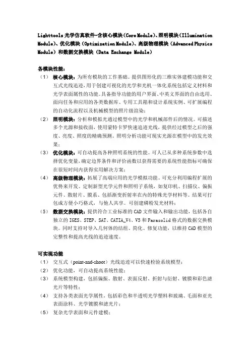
Lighttools光学仿真软件-含核心模块(Core Module)、照明模块(Illumination Module)、优化模块(Optimization Module)、高级物理模块(Advanced Physics Module)和数据交换模块(Data Exchange Module)各模块性能:(1)核心模块:为所有模块的工作基础。
提供图形化的三维实体建模功能和交互式光线追迹,用于创建可视化的光学和光机一体化系统包括定义材料和光学表面属性的功能。
具备指导功能的用户界面、中英文界面的自由选用、面向任务和应用的各类数据库、专用工具箱和设计系统实例、可扩展编程的自动化流程以及机械模型的照片级渲染;(2)照明模块:分析和模拟光通过模型中的光学和机械部件后的情况。
可描述多个光源和接收面,使用蒙特卡罗快速追迹光线,提供经过模型之后的强度、亮度、照度的精确预测。
照明分析功能可现实光源在模型中的发光效果;(3)优化模块:可自动提高各种照明系统的性能。
可人已从多种系统参数中选择优化变量,确定边界条件和评价函数以获得需要的系统性能指标可确保在很短时间内获得实用解决方案;(4)高级物理模块:拓展了高端应用的光学模拟功能。
可充分利用编程扩展的优势来开发、定制新型光学元件和照明子系统,如复印机、扫描仪、偏振元件、散射片、膜系、包括渐变折射率在内的特殊光学材料等。
结果可打包成方便小巧格式,与他人共享。
可创建磷粉发光材料;(5)数据交换模块:提供符合工业标准的CAD文件输入和输出功能,包括各自独立的IGES、STEP、SAT、CATIA_V4、V5和Parasolid格式的数据交换模块。
同时支持对导入几何体的结组、简化、修复功能,以维持CAD模型的完整性和提高光线的追迹速度。
可实现功能(1)交互式(point-and-shoot)光线追迹可以快速检验系统模型;(2)优化功能,可自动提高系统性能;(3)系统模型构建,包括偏振、散射、表面反射、折射与衍射、镀膜和彩色滤光片等特性;(4)支持各类表面光学属性,包括彩色和半透明光学塑料和玻璃、毛面和亚光表面涂料、光学镀膜和滤光片;(5)复杂光学表面和元件建模;(6)全系列光源模型;(7)接收面滤片功能;(8)支持基于测量的光线数据库光源,包括Radiant Source TM光源模型;(9)使用测试(BSDF)散射数据模拟散射效果;(10)自带建模库、光源库、表面涂饰库、镀膜库、滤色片库和面向应用的工具库;(11)交互式智能化的用户界面;(12)支持Visual Basic宏定制解决方案;(13)与CAD软件协同工作。
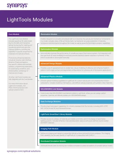
Core ModuleGeometry Creation and Editing• Lens primitives (rectangular or circular apertures)• Spline sweep and patch surfaces• Polyline sweeps and extrusions• Conic trough and revolved reflectors• Cylinders, blocks, spheres, toroids, and skinned solids• Union, intersection, subtraction boolean operations• Object trim operation• Move, rotate, scale, align• Copy, rectangular, and circular pattern copy• Multiple and partial immersion and cementing for solid objects• Pickups for parametric modeling• Grouping of model entitiesOptical Properties• Specular reflection/transmission/TIR with Fresnel losses• Diffuse transmission/reflection• Scatter models: mixed diffuse, narrow angle, and angle of incidence (AOI)• Volume scattering (Mie, user defined)• Scattering aim regions• User-defined coatings• Probabilistic ray splitting and importance sampling• Constant or varying optical density or transmittance vs. length• Index of refraction (constant, interpolated, standard dispersion formulas)• Surface patterns of 2D or 3D elements• Photorealistic rendering (Illumination Module needed for lit appearance)User Interface and Other Features• ActiveX interface for macro programming in MS Excel, VB, VC++, Matlab, Mathematica, and others • OpenGL-rendered graphics• Tabbed windows and editable spreadsheets• Multiple design views and navigation windows• Point-and-click, copy-and-paste, moving and resizing of windows• Extensive help featuresPoint-and-Shoot Ray Tracing• Parallel, diverging, or converging sets of rays• Individual rays, 2D ray fans, 3D ray grids• Sequential and non-sequential ray propagationLibraries• LED sources• Display films• Application and feature examplesIllumination ModulePowerful illumination analysis capabilities, such as photorealistic renderings that show the luminance effects of light sources in the model, simulate real-world conditions and reduce the need for physical prototypes.Illumination Analysis• Photorealistic Rendering• Photometric or radiometric analysis using forward and backward ray tracing• Illuminance, luminance, luminous intensity• Line charts, raster, contour, and surface charts• Colorimetric analysis: 1931 and 1976 CIE coordinates, correlated color temperature• RGB output display, CIE chromaticity chart• Post-processing of output data• Receiver data filtering using over a dozen filter types• Encircled and ensquared energy• Spectral power distribution• Multi-CPU processingSources and Receivers• Point sources• Volume and surface emitters (spheres, cylinders, blocks, toroids)• User-defined spatial, volume, and angular distributions• Source emittance aim regions• Spectral distributions: Blackbody, Gaussian, continuous, discrete, and user defined• Angular and spatial importance sampling• Ray data sources and Radiant Imaging source model support• Surface and far field receivers• Angular and spatial luminance meters• Receiver aperture sub-samplingOptimization ModuleThe Optimization Module gives designers tremendous flexibility to choose from hundreds of system parameters to designate as variables, constraints, and performance criteria in order to achieve the desired system performance.Illumination Optimization• Optimize illumination uniformity and/or flux on a receiver• Match target illumination distributions• Collimate and focus merit functions for non-sequential rays• Lagrange constraint handling• User-defined variables, constraints, and performance criteria• Vary any floating point model parameter• User-defined combinations of parameters• Bounded and unbounded variables• Backlight pattern optimization utility• Parameter sensitivity utility• Point-and-shoot ray merit functionsAdvanced Design ModuleThe Advanced Design Module leverages proprietary algorithms from Synopsys’ LucidShape products that automatically calculate and construct optical geometries based on user-defined illuminance and intensity patterns. This unique, functional approach gives designers the freedom to focus on overall design objectives rather than the implementation details of complex optical components.• Freeform Design features for modeling freeform reflective and refractive surfaces that are automatically shaped to form the resulting light pattern.• MacroFocal Reflector tool for designing multi-surface segmented reflectors, with different spreads for each facet.• Procedural Rectangle Lens tool for designing surfaces with pillowed optical arrays.• LED Lens tool for creating various types of freeform LED collimator lenses.Advanced Physics Module• Designers can take advantage of programming extensions to develop custom optical parts and advanced illumination subsystems using:• Phosphor particle modeling (single and multiple)• Gradient Index (GRIN) materials - used in copiers, scanners, and fiber optic telecommunication systems.• User-defined optical properties (UDOPs) - such as proprietary polarization components, scatterers, coatings, and other specialty optical materials.• Birefringent (uniaxial) materials - used in advanced applications such as AR/VR headsets and biomedical instruments.The results for UDOPs and birefringent materials can be packaged into a portable format and exchanged with your project team, customers, suppliers, and subcontractors.SOLIDWORKS Link ModuleThe SOLIDWORKS Link Module enables you to link SOLIDWORKS 3D opto-mechanical models to LightTools, where you can assign optical properties and use the Optimization Module to optimize your design. This module provides complete parametric interoperability between LightTools models and SOLIDWORKS.Data Exchange ModulesSupporting features for the Data Exchange Modules include the ability to group and simplify imported geometry and perform geometry repairs to maintain CAD model integrity and improve ray trace speed.Translators• SAT version 1.0 through 7.0• STEP AP 203 and AP 214• IGES version 5.3, including surfaces and solids• Parasolid• CATIA V4 and V5 (import and export)• Grouping and simplification of imported surfaces• Geometry repairLightTools SmartStart Library ModuleProvides access to a library of materials and media commonly used in the design of automotive lighting systems. Includes refractive index and absorption data as well as pre-defined volume scatter and BSDF materials.Imaging Path Module• Sequential ray tracing• Paraxial solves• Image path view• Spot diagram and transverse aberration plotsDistributed Simulation ModuleThe Distributed Simulation Module allows you to distribute Monte Carlo ray tracing over multiple computers to speed simulations of complex optical models.©2022 Synopsys, Inc. All rights reserved. Synopsys is a trademark of Synopsys, Inc. in the United States and other countries. A list of Synopsys trademarks isavailable at /copyright.html . All other names mentioned herein are trademarks or registered trademarks of their respective owners.。

运用LightTools设计背光显示2003年6月第一节背光设计简介本节介绍了如何运用LightTools来定义基本的背光。
本文供LightTools的初学用户使用,所以运用了很多相关的简单的例子并且包括产品的基本特性。
LightTools的高级用户可以跳过前半部分,直接到41页“高级背光设计”。
本节主要内容如下:·先决条件·什么是背光·普通光线输出技术·运用LightTools的计算机辅助设计·设置模拟·分析照明数据·更多照明数据导出先决条件要完成第一节中的练习,你首先得正确安装:·LightTools3.3版(或更高版本)。
·LightTools的系统(.lts)和库(.ent)文件确定可用,从光学研究协会网址上下载。
下载这些文件,首先在你的浏览器中输入:/LTFiles。
在“Designing Backlight Displays in LightTools”的栏目下点击BacklightFiles.zip。
把文件保存到硬盘然后把压缩文件解压到一个目录下(比如:C:\LTUser)。
什么是背光背光是指用于电子元件中的有一个要求背后出光的平面,其中可以包括小到PDA大到电视屏的电子设备。
典型的背光包括光源,导光板或者是所谓的light pipe。
光源一般置于导光板的一侧,以减小导光板的厚度。
侧光一般使用总的内反射来沿着演示器的长度方向来传播光,下边图表中所示就是典型的背光设计。
主要的要求就是均衡的光通过LCD的表面,而且光通量足够高,以便和日光环境有很好的对比度(这样你就可以在一台小型电脑或者掌上电子元件上边看见显示,比如,在室光条件下)。
如图2,设计的challenge就是使输出光方向于光传播方向,LCD平面刚刚好在导光板上方。
普通光输出技术从导光板以垂直于光传播方向输出光有好几种技术手段。
最普通的就是Printed light extraction和molded light extraction。
针对Lumileds K2光源设计一款LED LENS,达到准直的聚光效果,应用于LED手电筒或室内射灯。
基本设计步骤如下:1. LED光源模拟仿真;2.LED LENS初始结构建模;3.透镜模型的材料属性、光学属性设定;4.受光分析面,亮度计的设置;5.光线追迹,结果分析;6.根据分析结果调整透镜的几何模型参数,重复光线追迹过程,直至模拟仿真结果达到系统设计要求。
(在此我们采用LT的优化模块,可代替繁琐的模型更改过程,大大缩短产品开发周期)LED光源仿真:光源模型中详尽的参数设定以下介绍主要的参数(根据模拟目的不同,需要的参数也不同)光束(lm)或者是辐射功率(mW)光谱特性配光分布空间強度分布LED发光光谱拟合及解析蓝色LED和黄色荧光体组合生成白色LED类型是主流,可以在荧光体中制作吸收,散射,发光的模型LED几何模型可借助SolidWorks精确建模导入通过Solidworks Link模块 LightTools完全继承来自SolidWorks的特征树可为使用过Solidworks的工程师提供熟悉设计环境。
双向式数据交流功能保证了在LightTools 和Solidworks中的特征实时同步。
光源及几何模型数据的导入几何模型的材料属性、光学属性设定受光分析面,亮度计的设置设置系统的受光分析面,在受光面上设置亮度计进行光学分析。
对初始结构进行蒙特卡罗光线追迹LED光源,透镜模型,受光面参数均设定好之后方可进行光学仿真,仿真采用蒙特卡罗光线追迹。
通过优化,得到良好的聚光效果及很高的均匀度设置透镜表面曲线系数为变量,调用准直优化函数,运行自动优化。