17寸规格数
- 格式:pdf
- 大小:463.03 KB
- 文档页数:25

电视机规格尺寸对照表二为了能够更方便,各位朋友购买到适合客厅面积的电视机,下面就具体说说电视机尺寸对照。
1、 17寸电视机对角线长43.18厘米,长34.52厘米,宽25.89厘米。
2、 19寸电视机对角线长48.26厘米,长38.16厘米,宽28.62厘米。
3、 34寸电视机对角线长86.36厘米,长69.08厘米,宽51.81厘米。
4、 42寸电视机对角线长106.68厘米,长92.96厘米,宽52.29厘米。
5、 47寸电视机对角线长119.38厘米,长104厘米,宽58.5厘米。
以上的就是关于电视机尺寸对照表是什么的内容介绍了。
32寸电视的屏幕尺寸(以4:3为比例计算)长是65.024cm,宽是48.768cm ,(16:9)长69cm,宽39cm;人们说的电视机尺寸,实际上是电视机显示屏幕对角线的长短。
1、1英寸= 2.54 厘米,我国从上世纪80年代开始,已经法定用厘米替代英寸,但人们习惯上仍是以英寸来计量电视机的尺寸大小。
2、液晶电视机的寸数一般是指电视机屏幕对角线的长度,根据1英寸=2.54厘米换算,32寸电视机的屏幕对角线长度为32x2.54≈81cm。
由于32寸电视机的屏幕比例都为16:9,所以根据勾股定理可以推算出,32寸电视机的长度约为69厘米,宽度(即高度)约为39厘米。
下面是常见的电视尺寸对照表(不同品牌型号机型略有差异,但不会太大):32寸电视的长宽分别为88.55 cm和49.81cm;40寸电视的长宽分别为121.76 cm和68.49cm;48寸电视的长宽分别约为108 cm和63cm;50寸电视的长宽分别约为114 cm和64cm;55寸电视的长宽分别为121.76 cm和68.49cm;65寸电视长宽约145 cm、83.7cm;70寸电视长宽约155.06 cm、87.22cm;75寸电视长宽约166.03 cm,93.38cm;80寸电视长宽约181 cm、111cm;85寸电视的长宽约为172.72 cm和129.54cm;90寸电视长宽约205 cm、121cm;98寸电视长宽约216 cm、123cm;100寸的电视长宽大概是221.37 cm和124.52 cm。
![1寸到36寸照片的尺寸规格[1]](https://img.taocdn.com/s1/m/10f17a673169a4517723a3ff.png)
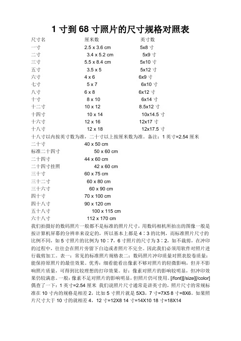
尺寸名厘米数英寸数一寸 2.5 x 3.6 cm 5x8寸二寸 3.4 x 5.2 cm 5x9寸三寸 5.5 x 8.4 cm 5x10寸五寸 3.5 x 5 5x12寸六寸 4 x 6 6x9寸七寸 5 x 7 6x10寸八寸 6 x 8 6x12寸十寸8 x 10 6x14寸十二寸10 x 12 8.5x12寸十四寸10 x 14 10x14.5寸十六寸12 x 16 12x17寸十八寸12 x 18 12x17.5寸十八寸以内按英寸数为准,二十寸以上按厘米数为准。
备注:1英寸=2.54厘米二十寸40 x 50 cm标准二十四寸50 x 60 cm二十四寸44 x 60 cm二十四寸挂照42 x 60 cm三十寸60 x 75 cm三十二寸60 x 80 cm三十六寸60 x 90 cm四十寸70 x 100 cm四十八寸90 x 120 cm五十八寸100 x 115 cm六十八寸112 x 170 cm我们拍摄好的数码照片一般都不是标准的照片尺寸,用数码相机所拍出的图像一般是按计算机屏幕的分辨率来设定的,所以基本上都是4∶3的比例,而标准照片尺寸的比例不同,如5寸照片的比例为10∶7,6寸照片的尺寸为3∶2,如不裁剪,在冲印的过程中,往往会在照片旁留下白边或者照片不完全。
因此我们必须用软件对照片进行裁剪加工。
表一:常见的标准照片规格表二:数码照片冲印质量对照表胶卷质量:能保持原照片的最佳效果。
优秀:细看能看出像素不够对照片的轻微影响,但并不影响照片质量,可得到比较理想的打印效果。
好:像素对照片的影响较明显,但冲印效果仍较满意。
一般:像素不足对照片的影响明显,但照片仍可使用。
[/font][/size][/color] 偶查了一下:1英寸=2.54厘米我们说照片尺寸通常是讲英寸的,照片尺寸的常规标准在10寸内的规格是相差2,比如5寸照片就是5X3,7寸=7X5 8寸=8X6。
如果照片尺寸大于10寸的就相差4,12寸=12X8 14寸=14X10 18寸=18X14照片的尺寸常见证件照对应尺寸1英寸25mm×35mm2英寸35mm×49mm3英寸35mm×52mm港澳通行证33mm×48mm赴美签证50mm×50mm日本签证45mm×45mm大二寸35mm×45mm护照33mm×48mm毕业生照33mm×48mm身份证22mm×32mm驾照21mm×26mm车照60mm×91mm***数码相机和可冲印照片最大尺寸对照表500万像素有效4915200,像素2560X1920。

标准行李箱尺寸规格表
标准行李箱的尺寸规格有很多种,常见的有16寸、17寸、18寸、20寸、22寸、24寸、26寸和28寸等。
具体尺寸如下:
16寸拉杆箱的尺寸为31cm43cm13cm;17寸拉杆箱的尺寸为32cm45cm18cm;18寸拉杆箱的尺寸为34cm44cm20cm;20寸拉杆箱的尺寸为34cm50cm20cm;22寸拉杆箱的尺寸为
39cm58cm24cm;24寸拉杆箱的尺寸为42cm68cm26cm;26寸拉杆箱的尺寸为45CM67cm28cm;28寸拉杆箱的尺寸为
47cm78cm28cm。
需要注意的是,以上尺寸均为行李箱的长宽高三边之和,单位为厘米。
另外,不同品牌和款式的行李箱尺寸可能略有差异,因此购买时应根据自己的需求和实际测量进行选择。
同时,在携带行李箱乘坐飞机时,应符合航空公司的行李规定,确保行李箱尺寸符合规定的要求。
1寸到68寸照片的尺寸规格对照表尺寸名厘米数英寸数一寸 2.5 x 3.6 cm 5x8寸二寸 3.4 x 5.2 cm 5x9寸三寸 5.5 x 8.4 cm 5x10寸五寸 3.5 x 5 5x12寸六寸 4 x 6 6x9寸七寸 5 x 7 6x10寸八寸 6 x 8 6x12寸十寸8 x 10 6x14寸十二寸10 x 12 8.5x12寸十四寸10 x 14 10x14.5寸十六寸12 x 16 12x17寸十八寸12 x 18 12x17.5寸十八寸以内按英寸数为准,二十寸以上按厘米数为准。
备注:1英寸=2.54厘米二十寸40 x 50 cm标准二十四寸50 x 60 cm二十四寸44 x 60 cm二十四寸挂照42 x 60 cm三十寸60 x 75 cm三十二寸60 x 80 cm三十六寸60 x 90 cm四十寸70 x 100 cm四十八寸90 x 120 cm五十八寸100 x 115 cm六十八寸112 x 170 cm我们拍摄好的数码照片一般都不是标准的照片尺寸,用数码相机所拍出的图像一般是按计算机屏幕的分辨率来设定的,所以基本上都是4∶3的比例,而标准照片尺寸的比例不同,如5寸照片的比例为10∶7,6寸照片的尺寸为3∶2,如不裁剪,在冲印的过程中,往往会在照片旁留下白边或者照片不完全。
因此我们必须用软件对照片进行裁剪加工。
表一:常见的标准照片规格表二:数码照片冲印质量对照表胶卷质量:能保持原照片的最佳效果。
优秀:细看能看出像素不够对照片的轻微影响,但并不影响照片质量,可得到比较理想的打印效果。
好:像素对照片的影响较明显,但冲印效果仍较满意。
一般:像素不足对照片的影响明显,但照片仍可使用。
[/font][/size][/color] 偶查了一下:1英寸=2.54厘米我们说照片尺寸通常是讲英寸的,照片尺寸的常规标准在10寸内的规格是相差2,比如5寸照片就是5X3,7寸=7X5 8寸=8X6。
![1寸到36寸照片的尺寸规格[1]](https://img.taocdn.com/s1/m/8bb922e7a417866fb94a8e23.png)
1寸到36寸照片的尺寸规格[1]尺寸名厘米数英寸数一寸 2.5 x 3.6 cm 5x8寸二寸 3.4 x 5.2 cm5x9寸三寸 5.5 x 8.4 cm5x10寸五寸 3.5 x 55x12寸六寸 4 x 66x9寸七寸 5 x 76x10寸八寸 6 x 86x12寸十寸8 x 106x14寸十二寸10 x 128.5x12寸十四寸10 x 1410x14.5寸十六寸12 x 1612x17寸十八寸12 x 1812x17.5寸十八寸以内按英寸数为准,二十寸以上按厘米数为准。
备注:1英寸=2.54厘米二十寸40 x 50 cm标准二十四寸50 x 60 cm二十四寸44 x 60 cm二十四寸挂照42 x 60 cm三十寸60 x 75 cm三十二寸60 x 80 cm三十六寸60 x 90 cm四十寸70 x 100 cm四十八寸90 x 120 cm五十八寸100 x 115 cm六十八寸112 x 170 cm我们拍摄好的数码照片一般都不是标准的照片尺寸,用数码相机所拍出的图像一般是按计算机屏幕的分辨率来设定的,所以基本上都是4∶3的比例,而标准照片尺寸的比例不同,如5寸照片的比例为10∶7,6寸照片的尺寸为3∶2,如不裁剪,在冲印的过程中,往往会在照片旁留下白边或者照片不完全。
因此我们必须用软件对照片进行裁剪加工。
表一:常见的标准照片规格表二:数码照片冲印质量对照表胶卷质量:能保持原照片的最佳效果。
优秀:细看能看出像素不够对照片的轻微影响,但并不影响照片质量,可得到比较理想的打印效果。
好:像素对照片的影响较明显,但冲印效果仍较满意。
一般:像素不足对照片的影响明显,但照片仍可使用。
[/font][/size][/color] 偶查了一下:1英寸=2.54厘米我们说照片尺寸通常是讲英寸的,照片尺寸的常规标准在10寸内的规格是相差2,比如5寸照片就是5X3,7寸=7X5 8寸=8X6。
如果照片尺寸大于10寸的就相差4,12寸=12X8 14寸=14X10 18寸=18X14照片的尺寸常见证件照对应尺寸1英寸25mm×35mm2英寸35mm×49mm3英寸35mm×52mm港澳通行证33mm×48mm赴美签证50mm×50mm日本签证45mm×45mm大二寸35mm×45mm护照33mm×48mm毕业生照33mm×48mm身份证22mm×32mm驾照21mm×26mm车照60mm×91mm***数码相机和可冲印照片最大尺寸对照表500万像素有效4915200,像素2560X1920。

飞机行李箱尺寸要求多少才符合标准我们常常在购置拉杆旅行箱的时候,总是会看到20、22、24寸等参数。
那么,这里的几寸是怎么计算的?在这里所说的寸是指英寸。
1英寸=2.54cm,1寸=3.3cm。
下各向您介绍,最常见的拉杆箱包的规格(参考,并不是尺度):16寸拉杆箱尺寸:31cm*43cm*13cm;17寸拉杆箱尺寸:32cm*45cm*18cm;18寸拉杆箱尺寸:34cm*44cm*20cm;20寸拉杆箱尺寸:34cm*50cm*20cm(长宽高加起来不大于115cm) 22寸拉杆箱尺寸:36cm*52cm*26cm;24寸拉杆箱尺寸:38cm*60cm*28cm(长宽高加起来不大于135),这个24寸的拉杆箱是有多大可①飞机上携带行李须知国内航班:持头等舱客票的旅客,每人可随身携带两件行李,持公务舱和经济舱客票的旅客,每人可随身携带一件行李。
每件行李体积不超过20×40×55厘米。
上述两项总重量均不超过5公斤。
国际航班:通常情况,每件行李体积不超过20×40×55厘米,手提行李总重量不超过7公斤。
(但各航空公司有特殊重量限制规定,请旅客留意机票上的提示,或向航空公司咨询)②免费托运行李额但当目的地为美洲时,其托运行李可以为两件,每件不超过23公斤,单件行李三边长度和不超过158厘米。
当超过时,旅客需要支付逾重行李费。
(部分航空公司有特殊重量限制规定,请旅客留意机票上的提示,或向航空公司咨询)逾重行李费收费标准。
旅客对逾重行李应付逾重行李费,国内航班逾重行李费率以每公斤按经济舱票价的1.5%计算,金额以元为单位。
各航空公司对国际航班逾重行李费率和计算方法不相同,旅客须按各航空公司规定办理。
>>>点击下页进入航空公司托运行李的这些潜规则。
尺寸名厘米数英寸数一寸 2.5 x 3.6cm 5x8寸二寸 3.4 x 5.2cm 5x9寸三寸 5.5 x 8.4cm 5x10寸五寸 3.5 x 5cm 5x12寸六寸 4 x 6cm 6x9寸七寸 5 x 7cm 6x10寸八寸 6 x 8cm 6x12寸十寸8 x 10cm 6x14寸十二寸10 x 12cm 8.5x12寸十四寸10 x 14cm 10x14.5寸十六寸12 x 16cm 12x17寸十八寸12 x 18cm 12x17.5寸十八寸以内按英寸数为准,二十寸以上按厘米数为准。
备注:1英寸=2.54厘米二十寸40 x 50 cm标准二十四寸50 x 60 cm二十四寸44 x 60 cm二十四寸挂照42 x 60 cm三十寸60 x 75 cm三十二寸60 x 80 cm三十六寸60 x 90 cm四十寸70 x 100 cm四十八寸90 x 120 cm五十八寸100 x 115 cm六十八寸112 x 170 cm我们拍摄好的数码照片一般都不是标准的照片尺寸,用数码相机所拍出的图像一般是按计算机屏幕的分辨率来设定的,所以基本上都是4∶3的比例,而标准照片尺寸的比例不同,如5寸照片的比例为10∶7,6寸照片的尺寸为3∶2,如不裁剪,在冲印的过程中,往往会在照片旁留下白边或者照片不完全。
因此我们必须用软件对照片进行裁剪加工。
表一:常见的标准照片规格表;二:数码照片冲印质量对照表胶卷质量:能保持原照片的最佳效果。
优秀:细看能看出像素不够对照片的轻微影响,但并不影响照片质量,可得到比较理想的打印效果。
好:像素对照片的影响较明显,但冲印效果仍较满意。
一般:像素不足对照片的影响明显,但照片仍可使用。
偶查了一下:1英寸=2.54厘米我们说照片尺寸通常是讲英寸的,照片尺寸的常规标准在10寸内的规格是相差2,比如5寸照片就是5X3,7寸=7X5 8寸=8X6。
如果照片尺寸大于10寸的就相差4,12寸=12X8 14寸=14X10 18寸=18X14照片的尺寸常见证件照对应尺寸1英寸25mm×35mm2英寸35mm×49mm3英寸35mm×52mm港澳通行证33mm×48mm赴美签证50mm×50mm日本签证45mm×45mm大二寸35mm×45mm护照33mm×48mm毕业生照33mm×48mm身份证22mm×32mm驾照21mm×26mm车照60mm×91mm数码相机和可冲印照片最大尺寸对照表:500万像素有效4915200,像素2560X1920。
尺寸名厘米数英寸数一寸 2.5 x 3.6 cm 5x8寸二寸 3.4 x 5.2 cm 5x9寸三寸 5.5 x 8.4 cm 5x10寸五寸 3.5 x 5 5x12寸六寸 4 x 6 6x9寸七寸 5 x 7 6x10寸八寸 6 x 8 6x12寸十寸 8 x 10 6x14寸十二寸 10 x 12 8.5x12寸十四寸 10 x 14 10x14.5寸十六寸 12 x 16 12x17寸十八寸 12 x 18 12x17.5寸十八寸以内按英寸数为准,二十寸以上按厘米数为准。
备注:1英寸=2.54厘米二十寸 40 x 50 cm标准二十四寸 50 x 60 cm二十四寸 44 x 60 cm二十四寸挂照 42 x 60 cm三十寸 60 x 75 cm三十二寸 60 x 80 cm三十六寸 60 x 90 cm四十寸 70 x 100 cm四十八寸 90 x 120 cm五十八寸 100 x 115 cm六十八寸 112 x 170 cm我们拍摄好的数码照片一般都不是标准的照片尺寸,用数码相机所拍出的图像一般是按计算机屏幕的分辨率来设定的,所以基本上都是4∶3的比例,而标准照片尺寸的比例不同,如5寸照片的比例为10∶7,6寸照片的尺寸为3∶2,如不裁剪,在冲印的过程中,往往会在照片旁留下白边或者照片不完全。
因此我们必须用软件对照片进行裁剪加工。
表一:常见的标准照片规格表二:数码照片冲印质量对照表胶卷质量:能保持原照片的最佳效果。
优秀:细看能看出像素不够对照片的轻微影响,但并不影响照片质量,可得到比较理想的打印效果。
好:像素对照片的影响较明显,但冲印效果仍较满意。
一般:像素不足对照片的影响明显,但照片仍可使用。
[/font][/size][/color] 偶查了一下:1英寸=2.54厘米我们说照片尺寸通常是讲英寸的,照片尺寸的常规标准在10寸内的规格是相差2,比如5寸照片就是5X3,7寸=7X5 8寸=8X6。
尺寸名厘米数英寸数小1寸(身份证大头照) 2.2*3.3cm1寸 2.5*3.5cm小2寸(护照) 3.2*4cm2寸 3.5*5.3cm5 寸5x3.5 12.7*8.9cm6 寸6x4 15.2*10.2cm7 寸7x5 17.8*12.7cm8 寸8x6 20.3*15.2cm10寸10x8 25.4*20.3cm12寸12x10 30.5*20.3cm15寸15x10 38.1*25.4cm16X12一般135底片放大的尺寸。
20X16135底片的极限尺寸。
24X20影楼放大最多的尺寸。
一寸 2.5 x 3.6 cm 5x8寸二寸 3.4 x 5.2 cm 5x9寸三寸 5.5 x 8.4 cm 5x10寸五寸 3.5 x 5 5x12寸六寸 4 x 6 6x9寸七寸 5 x 7 6x10寸八寸 6 x 8 6x12寸十寸8 x 10 6x14寸十二寸10 x 12 8.5x12寸十四寸10 x 14 10x14.5寸十六寸12 x 16 12x17寸十八寸12 x 18 12x17.5寸十八寸以内按英寸数为准,二十寸以上按厘米数为准。
备注:1英寸=2.54厘米二十寸40 x 50 cm标准二十四寸50 x 60 cm二十四寸44 x 60 cm二十四寸挂照42 x 60 cm三十寸60 x 75 cm三十二寸60 x 80 cm三十六寸60 x 90 cm四十寸70 x 100 cm四十八寸90 x 120 cm五十八寸100 x 115 cm六十八寸112 x 170 cm我们拍摄好的数码照片一般都不是标准的照片尺寸,用数码相机所拍出的图像一般是按计算机屏幕的分辨率来设定的,所以基本上都是4∶3的比例,而标准照片尺寸的比例不同,如5寸照片的比例为10∶7,6寸照片的尺寸为3∶2,如不裁剪,在冲印的过程中,往往会在照片旁留下白边或者照片不完全。
因此我们必须用软件对照片进行裁剪加工。
表一:常见的标准照片规格表二:数码照片冲印质量对照表胶卷质量:能保持原照片的最佳效果。
( ) Preliminary Specification(V) Final SpecificationModule 17.0” SXGA Color TFT-LCD Model Name M170ETN01.0Customer DateApproved byNote: This Specification is subject to change without notice.Checked &Approved byDate ChiYi Wu 2012/02/06 Prepared byArnold Hsu 2012/02/06Desktop Display Business Group / AU Optronics corporationContents1. Handling Precautions (4)2. General Description (5)2.1 Display Characteristics (5)3. Functional Block Diagram (10)4. Absolute Maximum Ratings (11)4.1 TFT LCD Module (11)4.2 Backlight Unit (11)4.3 Absolute Ratings of Environment (11)5. Electrical characteristics (12)5.1 TFT LCD Module (12)5.2 Backlight Unit (14)6. Signal Characteristic (15)6.1 Pixel Format Image (15)6.2 The Input Data Format (15)6.4 Timing Characteristics (18)6.5 Power ON/OFF Sequence (20)7. Connector & Pin Assignment (21)7.1 TFT LCD Module (21)7.2 Backlight Unit (22)8. Reliability Test (23)9. Shipping Label (24)10. Mechanical Characteristics (25)Record of RevisionVersion andPage Old description New Description Remark Date0.1 2011/11/15 All First Edition for Customer All0.2 2011/12/19 6 Update : Optical Characteristics/ Color /RevisedChromaticity Coordinates (CIE) & ColorCoordinates (CIE) White14 Update: CCFL Ignition Voltage /Operation Voltage / Power Consumption20 Update Power Sequence Timing21 Update connector Type Part Number25 Update Mechanical Characteristics1.0 2012/01/06 All Final Edition for Customer All Revised 1.1 2012/02/06 12 Update: Inrush Current Revised1. Handling Precautions1) Since front polarizer is easily damaged, pay attention not to scratch it.2) Be sure to turn off power supply when inserting or disconnecting from input connector.3) Wipe off water drop immediately. Long contact with water may cause discoloration or spots.4) When the panel surface is soiled, wipe it with absorbent cotton or other soft cloth.5) Since the panel is made of glass, it may break or crack if dropped or bumped on hard surface.6) Since CMOS LSI is used in this module, take care of static electricity and insure human earthwhen handling.7) Do not open or modify the Module Assembly.8) Do not press the reflector sheet at the back of the module to any directions.9) In case if a Module has to be put back into the packing container slot after once it was taken outfrom the container, do not press the center of the CCFL reflector edge. Instead, press at the farends of the CCFL Reflector edge softly. Otherwise the TFT Module may be damaged.10) At the insertion or removal of the Signal Interface Connector, be sure not to rotate nor tilt theInterface Connector of the TFT Module.11) After installation of the TFT Module into an enclosure, do not twist nor bend the TFT Module evenmomentary. At designing the enclosure, it should be taken into consideration that nobending/twisting forces are applied to the TFT Module from outside. Otherwise the TFT Modulemay be damaged.12) Cold cathode fluorescent lamp in LCD contains a small amount of mercury. Please follow localordinances or regulations for disposal.13) Small amount of materials having no flammability grade is used in the LCD module. The LCD moduleshould be supplied by power complied with requirements of Limited Power Source (IEC60950 or UL1950), or be applied exemption.14) The LCD module is designed so that the CCFL in it is supplied by Limited Current Circuit (IEC60950 orUL1950). Do not connect the CCFL in Hazardous Voltage Circuit.15) Please avoid touching COF position while you are doing mechanical design.2. General DescriptionThis specification applies to the 17 inch Color TFT-LCD Module M170ETN01.0.The display supports the SXGA+ (1280(H) x 1024(V)) screen format and 16.7M colors (RGB 6-bits+Hi-RFC data).All input signals are 2 Channel LVDS interface compatible.This module does not contain an inverter card for backlight.2.1 Display CharacteristicsThe following items are characteristics summary on the table under 25 ℃condition:Items Unit Specifications Screen Diagonal [mm] 432 (17.0”)Active Area [mm] 337.920(H) × 270.336(V)Pixels H x V 1280 × 3(RGB) × 1024Pixel Pitch [mm] 0.264(per one triad) × 0.264Pixel Arrangement R.G.B. Vertical StripeDisplay Mode Normally WhiteWhite Luminance [cd/m2] 250 (center,Typ)@7.5 mAContrast Ratio 1000 : 1 (Typ)Optical ResponseTime [msec] 5 (Typ)Nominal Input Voltage VDD [Volt] +5.0 (Typ)Power Consumption (VDD line + CCFL line) [Watt]11.05W => (Typ.)(without inverter, all black pattern)Weight [Grams] 1990 Typ.Physical Size (H x V x D) [mm] 358.5(H) x 296.5(V) Typ. x 15.8(D) Max. Electrical Interface Dual Channel LVDSSurface Treatment Anti-glare type, Hardness 3HSupport Color 16.7M colors (RGB 6-bits +Hi-FRC data) Temperature RangeOperatingStorage (Non-Operating) [o C][o C]0 to +50-20 to +60RoHS Compliance RoHS Compliance Digital Gamma turn on Compliance TCO5.0 Compliance2.2 Optical CharacteristicsThe optical characteristics are measured under stable conditions at 25℃ (Room Temperature):Item Unit ConditionsMin.Typ.Max.NoteHorizontal (Right) CR = 10 (Left) 140 170 -Viewing Angle [degree] Vertical (Up) CR = 10 (Down)140 160 - 1Luminance Uniformity [%] 9 Points 75 80 - 2, 3Rising- 3.5 6 Falling - 1.5 3 Optical Response Time [msec] Rising + Falling- 5 9 4, 6 Red x 0.623 0.653 0.683 Red y 0.298 0.328 0.358 Green x0.273 0.303 0.333 Green y 0.578 0.608 0.638 Blue x 0.114 0.144 0.174 Blue y 0.034 0.064 0.094 White x 0.283 0.313 0.343 Color / Chromaticity Coordinates (CIE 1931)White y0.299 0.329 0.359 4 White Luminance (At CCFL= 7.5mA) [cd/m 2 ]200 250 - 4 Contrast Ratio 600 1000 - 4 Cross Talk (At 75Hz) [%] - - 1.5 5 Flicker[dB]---207 Optical Equipment: BM-5A, BM-7, PR880, or equivalentNote 1: Definition of viewing angleViewing angle is the measurement of contrast ratio ≧10, at the screen center, over a 180° horizontal and 180° vertical range (off-normal viewing angles). The 180° viewing angle range is broken down as follows; 90° (θ) horizontal left and right and 90° (Φ) vertical, high (up) and low (down). Themeasurement direction is typically perpendicular to the display surface with the screen rotated about its center to develop the desired measurement viewing angle.Note 2: 9 points positionNote 3: The luminance uniformity of 9 points is defined by dividing the maximum luminance values by the minimum test point luminanceMinimum Luminance of 9 pointsδW9 =Maximum Luminance of 9 points50 %90 % 90 %50 %10 %10 %Note 4: Measurement methodThe LCD module should be stabilized at given temperature for 30 minutes to avoid abrupt temperature change during measuring. In order to stabilize the luminance, the measurement should be executed after lighting Backlight for 30 minutes in a stable, windless and dark room.Note 5: Definition of Cross Talk (CT) CT = | YB – YA | / YA × 100 (%) WhereYA = Luminance of measured location without gray level 0 pattern (cd/m2)YB = Luminance of measured location with gray level 0 pattern (cd/m2)Note 6: Definition of response time:The output signals of photo detector are measured when the input signals are changed from “Full Black” to “Full White” (rising time), and from “Full White” to “Full Black ”(falling time), respectively. The response time is interval between the 10% and 90% of amplitudes. Please refer to the figure as below.Note 7: Subchecker PatternR G B R G BR G B R G BR G B R G BMethod: Record dBV & DC value with (WESTAR)TRD-100Gray Level = L127Gray Level = L03. Functional Block DiagramThe following diagram shows the functional block of the 17.0 inches Color TFT-LCD Module:I/F PCB Interface: CCFL Connector:JAE FI-XB30SSLA-HF15 YEONHO 35001HS-02L P-TWO 187034-30091 CVILUX CP0502SL090 STM MSBKT2407P30HB Mating Type:FI-X30HL (Locked Type) FI-X30H (Unlocked Type)4. Absolute Maximum RatingsAbsolute maximum ratings of the module is as following:4.1 TFT LCD ModuleItem Symbol Min Max Unit Conditions Logic/LCD Drive Voltage VIN -0.3 6 [Volt] Note 1,24.2 Backlight UnitItem Symbol Min Max Unit Conditions CCFL Current ICFL - 8 [mA] rms Note 1,24.3 Absolute Ratings of EnvironmentItem Symbol Min Max Unit Conditions Operating Humidity HOP 5 90 [%RH]Note 3 Storage Temperature TST -20 +60 [o C]Storage Humidity HST 5 90 [%RH]Note 1: With in Ta (25℃)Note 2: Permanent damage to the device may occur if exceed maximum valuesNote 3: For quality performance, please refer to AUO IIS (Incoming Inspection Standard).Operating Range Storage Range5. Electrical characteristics 5.1 TFT LCD Module5.1.1 Power SpecificationInput power specifications are as follows:Note 1: Measurement conditions:Symbol Parameter Min Typ Max Unit ConditionsVDDLogic/LCD DriveVoltage 4.5 5.0 5.5 [Volt] +/-10%- 0.47 0.56 [A] VDD= 5.0V, All Black Pattern At 60Hz, IDDInput Current0.59 0.71 VDD= 5.0V, All Black Pattern At 75Hz, - 2.35 2.82 [Watt] VDD= 5.0V, All Black Pattern At 60Hz PDD VDD Power2.953.54 VDD= 5.0V, All Black Pattern At 75Hz IRush Inrush Current - - 3.0 [A]Note 1VDDrpAllowable Logic/LCD Drive Ripple Voltage--500[mV] p-p VDD= 5.0V, All Black Pattern At 75Hz5.0V5.1.2 Signal Electrical CharacteristicsInput signals shall be low or Hi-Z state when Vin is offIt is recommended to refer the specifications of SN75LVDS82DGG (Texas Instruments) in detail. Each signal characteristics are as follows;Symbol Parameter Min Typ Max Units ConditionVTH Differential Input HighThreshold- - +100 [mV]VICM = 1.2VNoteVTL Differential Input LowThreshold-100 - - [mV]VICM = 1.2VNote│VID│Input Differential Voltage 100 400 600 [mV] NoteVICM Differential Input CommonMode Voltage+1.0 +1.2 +1.5 [V]VTH-VTL = 200mV(min)NoteNote: LVDS Signal Waveform5.2 Backlight UnitParameter guideline for CCFL InverterParameter Min. Typ. Max. Unit Condition CCFL standard current(ISCFL) 7 7.5 8 [mA] rms (Ta=25o C) Note 2 CCFL Operation Current (IRCFL) 3.5 7.5 8 [mA] rms (Ta=25o C) Note 2 CCFL Frequency (FCFL) 40 60 80 [KHz] (Ta=25o C) Note 3,4 CCFL Ignition Voltage (ViCFL, Ta= 0℃) 1230 - [Volt] rms (Ta=0o C)Note 5 CCFL Ignition Voltage (ViCF, Ta= 25℃) 1025 - [Volt] rms (Ta=25o C) Note 5CCFL Operation Voltage (VCFL)528@ 7.5mA580@ 7.5mA638@ 7.5mA[Volt] rms (Ta=25o C) Note 6CCFL Power Consumption (PCFL) 7.92 8.7 9.57 [Watt] (Ta=25o C) Note 6CCFL Life Time (LTCFL) 50,000 - - [Hour] (Ta=25o C)Note 1: Typ. are AUO recommended design points.*1 All of characteristics listed are measured under the condition using the AUO test inverter.*2 In case of using an inverter other than listed, it is recommended to check the inverter carefully.Sometimes, interfering noise stripes appear on the screen, and substandard luminance or flickerat low power may happen.*3 In designing an inverter, it is suggested to check safety circuit very carefully. Impedance of CCFL, for instance, becomes more than 1 [M ohm] when CCFL is damaged.*4 Generally, CCFL has some amount of delay time after applying kick-off voltage. It is recommended to keep on applying kick-off voltage for 1 [Sec] until discharge.*5 Reducing CCFL current increases CCFL discharge voltage and generally increases CCFL discharge frequency. So all the parameters of an inverter should be carefully designed so as notto produce too much leakage current from high-voltage output of the inverter.Note 2: It should be employed the inverter which has “Duty Dimming”, if IRCFL is less than 3mA.Note 3: CCFL discharge frequency should be carefully determined to avoid interference between inverter and TFT LCD.Note 4: The frequency range will not affect to lamp life and reliability characteristics.Note 5: CCFL inverter should be able to give out a power that has a generating capacity of over 1,560 voltage. Lamp units need 1,560 voltage minimum for ignition.Note 6: The variance of CCFL power consumption is ±10%. Calculator value for reference (ISCFL × VCFL × 2= PCFL)Note 7:Definition of Life time: Brightness becomes 50%. The typical life time CCFL in on the condition at 7.5 m A lamp current.6. Signal Characteristic 6.1 Pixel Format ImageFollowing figure shows the relationship of the input signals and LCD pixel format.121279 1280 1st Line1024th Line6.2 The Input Data FormatNote1: Normally, DE, VS, HS on EVEN channel are not used. Note2: Please follow PSWG. Note3: 8-bit in6.3 Signal DescriptionThe module using a pair of LVDS receiver SN75LVDS82(Texas Instruments) or compatible. LVDS is a differential signal technology for LCD interface and high speed data transfer device. Transmitter shall be SN75LVDS83(negative edge sampling) or compatible. The first LVDS port(RxOxxx) transmits odd pixels while the second LVDS port(RxExxx) transmits even pixels.PIN # SIGNAL NAME DESCRIPTION1 RxO0- Negative LVDS differential data input (Odd data)2 RxO0+ Positive LVDS differential data input (Odd data)3 RxO1- Negative LVDS differential data input (Odd data)4 RxO1+ Positive LVDS differential data input (Odd data)5 RxO2- Negative LVDS differential data input (Odd data, H-Sync,V-Sync,DSPTMG)6 RxO2+ Positive LVDS differential data input (Odd data, H-Sync,V-Sync,DSPTMG)7 GND Power Ground8 RxOC- Negative LVDS differential clock input (Odd clock)9 RxOC+ Positive LVDS differential clock input (Odd clock)10 RxO3- Negative LVDS differential data input (Odd data)11 RxO3+ Positive LVDS differential data input (Odd data)12 RxE0- Negative LVDS differential data input (Even data)13 RxE0+ Positive LVDS differential data input (Even data)14 GND Power Ground15 RxE1- Negative LVDS differential data input (Even data)16 RxE1+ Positive LVDS differential data input (Even data)17 GND Power Ground18 RxE2- Negative LVDS differential data input (Even data)19 RxE2+ Positive LVDS differential data input (Even data)20 RxEC- Negative LVDS differential clock input (Even clock)21 RxEC+ Positive LVDS differential clock input (Even clock)22 RxE3- Negative LVDS differential data input (Even data)23 RxE3+ Positive LVDS differential data input (Even data)24 GND Power Ground25 GND Power Ground (For AUO test Aging+HVS mode )26 NC No contact27 GND Power Ground28 VCC +5.0V Power Supply29 VCC +5.0V Power Supply30 VCC +5.0V Power SupplyNote1: Start from left sideNote2: Input signals of odd and even clock shall be the same timing. Note3: Please follow PSWG.RxOIN0-VCC6.4 Timing Characteristics6.4.1 Timing CharacteristicsBasically, interface timings described here is not actual input timing of LCD module but output timing of SN75LVDS82DGG (Texas Instruments) or equivalent.Signal Item Symbol Min Typ Max Unit Period Tv 1032 1066 1150 Th Active Tdisp(v) 1024 1024 1024 Th Vertical SectionBlanking Tbp(v)+Tfp(v)+PWvs8 42 126 Th Period Th 780 844 2048 Tclk Active Tdisp(h) 640 640 640 Tclk Horizontal SectionBlanking Tbp(h)+Tfp(h)+PWhs140 204 1408 Tclk Period Tclk 14.81 18.52 25 ns Clock Frequency Freq 40 54 67.5 MHz Frame rateFrame rateF506075HzNote : DE mode only6.4.2 Timing DigramHsyncPixel N1MInvalid DataTdisp(v)10DEDE Invalid Data RGB DataTh2RGB Data (Even)39M-1Invalid Data1N HsyncM-2Invalid Data1165M-3Vsync Invalid DataCLKM-5Invalid DataM-472Tbp(h)Pixel Pixel Pixel Pixel Pixel RGB Data(Odd)12Tbp(v)Tclk Pixel Pixel Pixel Pixel PixelPixel Pixel PixelPixelPixel Pixel Pixel 8434TvTdisp(h)LineLineLineLineLineLineTfp(v)Tfp(h)PWvsPWhs6.5 Power ON/OFF SequenceVDD power and lamp on/off sequence is as follows. Interface signals are also shown in the chart. Signals from any system shall be Hi-Z state or low level when VDD is off.Power Sequence TimingValueParameterMin.Max. UnitT1 0.5 10 [msec] T2 0 50 [msec] T3 500 - [msec] T4 200 - [msec] T5 40 - [msec] T61000-[msec] Note: The values of the table are follow PSWG.0VPower Supply VDDLVDS SignalBacklight OnNote : Insert a white pattern after valid data and last until VDD falls to 10%7. Connector & Pin AssignmentPhysical interface is described as for the connector on module.These connectors are capable of accommodating the following signals and will be following components.7.1 TFT LCD Module7.1.1 ConnectorConnector Name / Designation Interface Connector / Interface card Manufacturer JAE / P-TWO / STMType Part Number FI-XB30SSLA-HF15/187034-3009/ MSBKT2407P30HBMating Housing Part Number JAE FI-X30HL7.1.2 Pin AssignmentPin#Signal Name Pin#Signal Name1 RxOIN0-2 RxOIN0+3 RxOIN1-4 RxOIN1+5 RxOIN2-6 RxOIN2+7 GND8 RxOCLKIN-9 RxOCLKIN+ 10 RxOIN3-11 RxOIN3+ 12 RxEIN0-13 RxEIN0+ 14 GND15 RxEIN1- 16 RxEIN1+17 GND18 RxEIN2-19 RxEIN2+ 20 RxECLKIN-21 RxECLKIN+ 22 RxEIN3-23 RxEIN3+ 24 GND25 GND (AGMODE+HVS) 26 NC27 GND 28 VCC29 VCC 30 VCC7.2 Backlight UnitPhysical interface is described as for the connector on module. These connectors are capable of accommodating the following signals and will be following components.Connector Name / Designation Lamp Connector / Backlight lamp Manufacturer YEONHO or CVILUXType Part Number 35001HS-02L or CP0502SL090Mating Type Part Number 35001WR-02L or CP0502P1ML07.2.1 Signal for Lamp connectorConnector No. Pin No. Input Color Function1 Hot1 Pink High Voltage (Lamp 1) Upper CN12 Cold1 White Low Voltage (Lamp 1)Connector No. Pin No. Input Color Function1 Hot1 Pink High Voltage (Lamp 2) Lower CN22 Cold1 White Low Voltage (Lamp 2)8. Reliability TestEnvironment test conditions are listed as following table.Items Required Condition Note Temperature Humidity Bias (THB) Ta= 50,℃80%RH, 300hoursHigh Temperature Operation (HTO) Ta= 50,℃50%RH, 300hoursLow Temperature Operation (LTO) Ta= 0, 300hours℃High Temperature Storage (HTS) Ta= 60, 300hours℃Low Temperature Storage (LTS) Ta= -20, 300hours℃Vibration Test (Non-operation) Acceleration: 1.5 GWave: RandomFrequency: 10 - 200 - 10 Hz Sweep: 30 Minutes each Axis (X, Y, Z)Shock Test (Non-operation) Acceleration: 50 GWave: Half-sineActive Time: 20 msDirection: ±X,±Y,±Z (one time for each Axis)Drop Test Height: 60 cm, package testThermal Shock Test (TST) -20℃/30min, 60℃/30min, 100 cycles 1 On/Off Test On/10sec, Off/10sec, 30,000 cyclesContact Discharge: ± 8KV, 150pF(330Ω ) 1sec,8 points, 25 times/ point.ESD (ElectroStatic Discharge)Air Discharge: ± 15KV, 150pF(330Ω ) 1sec8 points, 25 times/ point.2Altitude Test Operation:10,000 ft Non-Operation:30,000 ftNote 1: The TFT-LCD module will not sustain damage after being subjected to 100 cycles of rapid temperature change. A cycle of rapid temperature change consists of varying the temperature from -20℃to 60℃, and back again. Power is not applied during the test. After temperature cycling, the unit is placed in normal room ambient for at least 4 hours before power on.Note 2: According to EN61000-4-2 , ESD class B: Some performance degradation allowed. No data lost.Self-recoverable. No hardware failures.9. Shipping LabelThe shipping label format is shown as below.M170ETN01.010. Mechanical Characteristics。