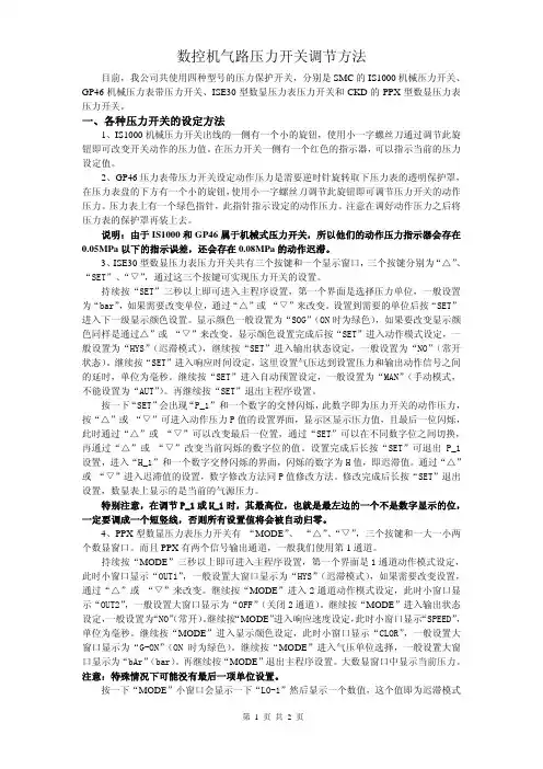
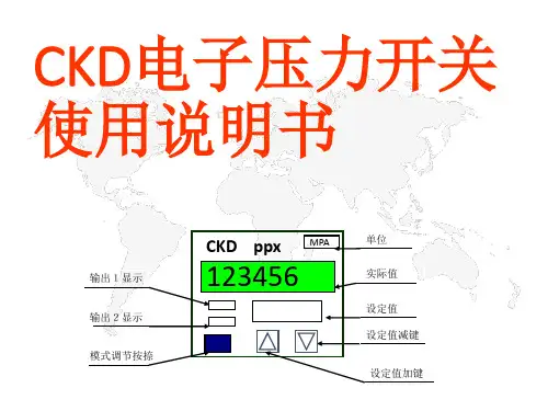
CKD电子压力开关使用说明书
- 格式:ppt
- 大小:202.50 KB
- 文档页数:15

e-mail:**************For latest product manuals:User’s GuideLCKD SERIESSubminiature CompressionLoad CellsShop online at1Each LCKD Series Load Cell incorporates a small printed circuit board into the load cell’s lead wire. DO NOT remove this board or cut the cable between the compensation board and load cell. Removal of this board voids the calibration and warranty of the load cell.GeneralThe OMEGA®LCKD Series subminiature compression load cells arecompression-only units that are highly cost-effective. To ensureexcellent long-term stability and reliability in severe environments, theLCKD Series utilize high quality strain gages, precision gagingtechniques and all stainless steel construction. These units have a loadbutton machined as an integral part of the basic load cell. The load cellis designed to operate by mounting on a flat surface. The LCKD mustrest on a flat surface the same diameter as the D1dimension for properoperation.Shunt CalibrationThe LCKD Series are highly accurate millivolt output type load cellswith shunt calibrator for quick calibration checks. Shunt calibrationallows the user to install and calibrate the instrument in the fieldwithout the use of a dead weight tester. A 59 kilohm resistor is shortedacross negative excitation and negative signal output at the factory,which produces a simulated millivolt signal out of the transducer. Theshunt calibration signal is equivalent to a simulated pressure of:Shunt Cal mV/VSimulated Load = x Full Scale LoadCalibration Factor mV/VExample: Model LCKDWhere:Calibration Factor - 2.0315 mV/VShunt Cal - 1.4962 mV/VSimulated Load = 1.4962x 50 = 36.852.0315To set up the transducer in the field, follow these steps:1. Connect transducer excitation terminals to dc power supply.2. Connect transducer signal output terminals to readout instrument(DVM, Analog meter, etc.)3. Turn power on.4. Null transducer signal output with zero adjust potentiometer on meter.5. Short a 59 kilohm resistor across negative excitation and negativesignal output.6. Adjust the span potentiometer until the readout instrument reads thesimulated load as computed above (or that percent of full scalepressure).7. Remove 59 kilohm resistor and repeat steps 4 to 6 if necessary.(Span and Zero adjust pots may interact).8. The meter is now calibrated.IMPORTANT:Every load cell comes with a calibration sheet stating its full scale output, and this manual. Please save both.Specifications:Signal Output:See calibration sheetLinearity and Hysteresis:±0.25% full scaleRepeatability:±0.1% full scaleCompensated Temperature Range:60 to 160°F (16 to 71°C)Operating Temperature Range:-65°to 225°F (-54 to 107°C)Temperature Effect:Zero 0.01% full scale/°F;Span 0.01% of reading/°F Bridge Resistance:350 ohm bonded foil gageExcitation Voltage: 5 Vdc, 7 Vdc max.Full Scale Deflection:0.001" to 0.003"Safe Overload:150%Construction:Stainless SteelElectrical: 5 ft. four conductor cableWeight:<0.5 oz.WIRING CODERED(+) EXCITATIONBLACK(–) EXCITATIONGREEN(–) OUTPUTWHITE (+) OUTPUT2M4087-0305It is the policy of OMEGA Engineering, Inc. to comply with all worldwide safety and EMC/EMI regulations that apply. OMEGA is constantly pursuing certification of its products to the European New Approach Directives. OMEGA will add the CE mark to every appropriate device upon certification.The information contained in this document is believed to be correct, but OMEGA accepts no liability for any errors it contains, and reserves the right to alter specifications without notice.WARNING: These products are not designed for use in, and should not be used for, human applications.Direct all warranty and repair requests/inquiries to the OMEGA Customer Service Department. BEFORE RET URNING ANY PRODUCT (S) T O OMEGA, PURCHASER MUST OBT AIN AN AUT HORIZED RET URN (AR) NUMBER FROM OMEGA’S CUST OMER SERVICE DEPART MENT (IN ORDER T O AVOID PROCESSING DELAYS). T he assigned AR number should then be marked on the outside of the return package and on any correspondence.The purchaser is responsible for shipping charges, freight, insurance and proper packaging to prevent breakage in transit. FOR WARRANTY RETURNS, please have the following informa-tion available BEFORE contacting OMEGA:1.Purchase Order number under which the product was PURCHASED,2.Model and serial number of the product under warranty, and3.Repair instructions and/or specific problems relative to the product.FOR NON-WARRANTY REPAIRS,consult OMEGA for cur-rent repair charges. Have the following information avail-able BEFORE contacting OMEGA:1. Purchase Order number to cover the COST of the repair,2.Model and serial number of the product, and3.Repair instructions and/or specific problems relative to the product.OMEGA’s policy is to make running changes, not model changes, whenever an improvement is possible. This affords our customers the latest in technology and engineering.OMEGA is a registered trademark of OMEGA ENGINEERING, INC.© Copyright 2005 OMEGA ENGINEERING, INC. All rights reserved. T his document may not be copied, photocopied, reproduced, translated, or reduced to any electronic medium or machine-readable form, in whole or in part, without the prior written consent of OMEGA ENGINEERING, INC.Servicing North America:U.S.A.:One Omega Drive, Box 4047ISO 9001 Certified Stamford, CT 06907-0047Tel: (203) 359-1660FAX: (203) 359-7700e-mail:**************Canada:976 BergarLaval (Quebec) H7L 5A1, Canada Tel: (514) 856-6928FAX: (514) 856-6886e-mail:*************For immediate technical or application assistance:U.S.A. andSales Service: 1-800-826-6342 / 1-800-TC-OMEGA Canada:Customer Service: 1-800-622-2378 / 1-800-622-BEST Engineering Service: 1-800-872-9436 / 1-800-USA-WHEN Mexico:En Espan ˜ol: (001) 203-359-7803e-mail:*****************FAX: (001) 203-359-7807**************.mxServicing Europe:Benelux:Postbus 8034, 1180 LA Amstelveen, The Netherlands Tel: +31 (0)20 3472121FAX: +31 (0)20 6434643Toll Free in Benelux: 0800 0993344e-mail:*****************Czech Frystatska 184, 733 01 Karviná, Czech Republic Republic:Tel: +420 (0)59 6311899FAX: +420 (0)59 6311114Toll Free: 0800-1-66342e-mail:*****************France:11, rue Jacques Cartier, 78280 Guyancourt, France Tel: +33 (0)1 61 37 2900FAX: +33 (0)1 30 57 5427Toll Free in France: 0800 466 342e-mail:**************Germany/Daimlerstrasse 26, D-75392 Deckenpfronn, Germany Austria:Tel: +49 (0)7056 9398-0FAX: +49 (0)7056 9398-29TollFreeinGermany************e-mail:*************United One Omega Drive, River Bend Technology Centre Kingdom:Northbank, Irlam, ManchesterISO 9002 Certified M44 5BD United KingdomTel: +44 (0)161 777 6611FAX: +44 (0)161 777 6622Toll Free in United Kingdom: 0800-488-488e-mail:**************.uk。
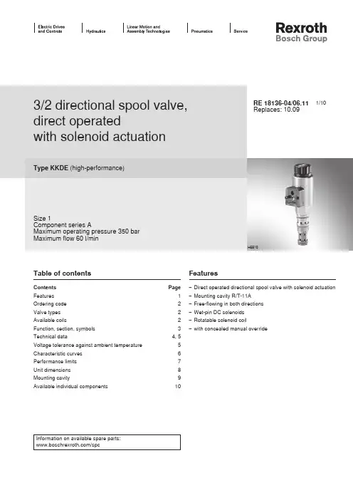
数控机气路压力开关调节方法目前,我公司共使用四种型号的压力保护开关,分别是SMC的IS1000机械压力开关、GP46机械压力表带压力开关、ISE30型数显压力表压力开关和CKD的PPX型数显压力表压力开关。
一、各种压力开关的设定方法1、IS1000机械压力开关出线的一侧有一个小的旋钮,使用小一字螺丝刀通过调节此旋钮即可改变开关动作的压力值。
在压力开关一侧有一个红色的指示器,可以指示当前的压力设定值。
2、GP46压力表带压力开关设定动作压力是需要逆时针旋转取下压力表的透明保护罩,在压力表盘的下方有一个小的旋钮,使用小一字螺丝刀调节此旋钮即可调节压力开关的动作压力。
压力表上有一个绿色指针,此指针指示设定的动作压力。
注意在调好动作压力之后将压力表的保护罩再装上去。
说明:由于IS1000和GP46属于机械式压力开关,所以他们的动作压力指示器会存在0.05MPa以下的指示误差,还会存在0.08MPa的动作迟滞。
3、ISE30型数显压力表压力开关共有三个按键和一个显示窗口,三个按键分别为“△”、“SET”、“▽”,通过这三个按键可实现压力开关的设置。
持续按“SET”三秒以上即可进入主程序设置,第一个界面是选择压力单位,一般设置为“bar”,如果需要改变单位,通过“△”或 “▽”来改变。
设置到需要的单位后按“SET”进入下一级显示颜色设置。
显示颜色一般设置为“SOG”(ON时为绿色),如果要改变显示颜色同样是通过△”或 “▽”来改变。
显示颜色设置完成后按“SET”进入动作模式设定,一般设置为“HYS”(迟滞模式),继续按“SET”进入输出状态设定,一般设置为“NO”(常开状态)。
继续按“SET”进入响应时间设定,这里设置气压达到设置压力和输出动作信号之间的延时,单位为毫秒。
继续按“SET”进入自动预置设定,一般设置为“MAN”(手动模式,不能设置为“AUT”)。
再继续按“SET”退出主程序设置。
按一下“SET”会出现“P_1”和一个数字的交替闪烁,此数字即为压力开关的动作压力,按“△”或 “▽”可进入动作压力P值的设置界面,显示区显示压力值,且最后一位闪烁,此时通过“△”或 “▽”可以改变最后一位置,通过“SET”可以在不同数字位之间切换,再通过“△”或 “▽”改变当前闪烁的数字位的值。
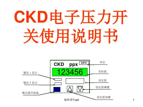
1/103/2 directional spool valve, direct operatedwith solenoid actuationType KKDE (high-performance)Size 1Component series AMaximum operating pressure 350 bar Maximum flow 60 l/minRE 18136-04/06.11Replaces: 10.09Table of contentsContents PageFeatures 1Ordering code 2Valve types 2Available coils2Function, section, symbols 3Technical data4, 5Voltage tolerance against ambient temperature 5Characteristic curves 6Performance limits 7Unit dimensions 8Mounting cavity9Available individual components10Features– Direct operated directional spool valve with solenoid actuation – Mounting cavity R/T-11A – Free-flowing in both directions – Wet-pin DC solenoids – Rotatable solenoid coil – with concealed manual overrideH6810Information on available spare parts:/spcOrdering code (valve without coil) 1)Spool symbolwithout manual override "N0"with concealed manual override "N9"Type Material no.Type Material no.C KKDER1CA/HN0V R901070094KKDER1CA/HN9V R901070103UKKDER1UA/HN0VR901070099KKDER1UA/HN9VR901070105Available coils (separate order) 1)Direct voltage DC 4)Material no. for coil with connector 3)"K4"03pol (2+PE)DIN EN 175301-803"K40"02pol K40DT 04-2PA, make Deutsch"C4"02pol C4/Z30AMP Junior Timer 12 V R900991678R900729189R90031581824 VR900991121R900729190R9003158191) Complete valves with mounted coil upon request 2) With transition function during the switching process 3) Mating connectors, separate order, see data sheet 08006Valve types (without coil) 1)4) Other voltages upon request5) Screwable manual override "N10" possible(Material no. R901051231, separate order)71Function, section, symbolsGeneralThe 3/2 directional spool valves are direct operated, pres-sure-compensated cartridge valves. They control the start,stop and direction of a flow and basically comprise a hous-ing (1) with a movably mounted socket (2), the controlspool (5)and a return spring (4).FunctionIn the de-energized condition, the control spool (5) is heldin the initial position by the return spring (4). The controlspool (5) is actuated by wet-pin DC solenoids (3). The sym-bols are realized by different spools (C or U). The mainports ①, ②, and ③ are suitable for a continuous load with anoperating pressure of 350 bar and the flow can be directedinto both directions (see symbols).The manual override (6) allows for the switching of the valvewithout solenoid energization. It is also available in screwableversion "N10" (7) (see page 2).Version "K4"(with mating connector)Version "C4"Symbol "C"Symbol "U"Type KKDER1CA/HN9VTechnical data (For applications outside these parameters, please consult us!)hydraulicMaximum operating pressure bar 350 (at all ports)Maximum flow l/min 60Hydraulic fluidSee table below Hydraulic fluid temperature range °C –40 to +80Viscosity rangemm 2/s 4 to 500Maximum permitted degree of contamination of the hydraulic fluid - cleanliness class according to ISO 4406 (c)Class 20/18/15 1)Load cycles 10 million (at 350 bar )generalWeight– Valve kg 0.3– Coilkg 0.25Installation position Any Ambient temperature range°C –40 to +1101) The cleanliness classes specified for the components mustbe adhered to in hydraulic systems. Effective filtration pre-vents faults and at the same time increases the service life of the components.For the selection of the filters see /filter.1201101009080706050-30-1001030507090110-20204060801001201101009080706050Technical data (For applications outside these parameters, please consult us!)electricVoltage type Direct voltage Supply voltage 2)V 12 DC; 24 DCVoltage tolerance against ambient temperature See characteristic curve below Power consumption W 22Duty cycle%See characteristic curve below Maximum coil temperature 3)°C 150Switching time according to ISO 6403(solenoid horizontal)– ON ms ≤ 80– OFF ms ≤ 50Maximum switching frequency cy/h 15000Protection class according to VDE 0470-1(DIN EN 60529)DIN 40050-9– Version "K4"IP 65 with mating connector mounted and locked – Version "C4"IP 66 with mating connector mounted and lockedIP 69K with Rexroth mating connector (Material no. R901022127)– Version "K40"IP 69K with mating connector mounted and locked2) Other voltages upon request3) Due to the surface temperatures of the solenoid coils, thestandards ISO 13732-1 and EN 982 need to be adhered to!At the electrical connection "K4", the protective earth-ing conductor (PE ) has to be connected properly.Voltage tolerance against ambient temperature; duty cycleA d m i s s i b l e s u p p l y v o l t a g e o f t h e n o m i n a l v o l t a g e i n % →Ambient temperature in °C →D u t y c y c l e i n % →1Maximum voltage 2Duty cycle3Minimum response voltage Admissible supply voltage rangeVoltage range and duty cycle depending on the ambient temperature5101520253001020304050215101520253035010203040506012Characteristic curves (measured with HLP46, ϑoil = 40 °C ± 5 °C and 24 V coil)Flow in l/min →P r e s s u r e d i f f e r e n t i a l i n b a r →∆p -q V characteristic curves – symbol C1① → ②② → ①2③ → ②② → ③1① → ②② → ①2③ → ②② → ③Flow in l/min →P r e s s u r e d i f f e r e n t i a l i n b a r →∆p -q V characteristic curves – symbol U123405010015020025030035040001020304050607012340501001502002503003504000102030405060Performance limits (measured with HLP46, ϑoil = 40 °C ± 5 °C and 24 V coil)Flow in l/min →O p e r a t i n g p r e s s u r e i n b a r →1① → ②2② → ③3③ → ②4② → ①1① → ②2② → ③3③ → ②4② → ①Symbol CFlow in l/min →O p e r a t i n g p r e s s u r e i n b a r →Symbol UAttention!The performance limits were determined when the solenoids were at op-erating temperature and at 10 % undervoltage.Unit dimensions (dimensions in mm)① = Main port 1② = Main port 2③ = Main port 3LS = Location shoulder12345Dimension () for "K4" mating connector, with circuitry 6Version "K40"7Version "C4"8Nut, tightening torque M A = 5+1 Nm 9Coil (separate order, see page 2)10Concealed manual override "N9", optional 11Screwable manual override "N10"(separate order, see page 2)Rz 321)Mounting cavity R/T-11A; 3 main ports; thread M20 x 1.5 (dimensions in mm)1) Differing from T-11A2) All seal ring insertion faces are rounded and free of burrs3) With counterbore4) Depth for moving parts① = Main port 1② = Main port 2③ = Main port 3LS = Location shoulderTolerance for all angles±0.5°Bosch Rexroth AG HydraulicsZum Eisengießer 197816 Lohr am Main, Germany Phone +49 (0) 93 52 / 18-0***************************** www.boschrexroth.de © This document, as well as the data, specifications and other informa-tion set forth in it, are the exclusive property of Bosch Rexroth AG. It may not be reproduced or given to third parties without its consent.The data specified above only serve to describe the product. No state-ments concerning a certain condition or suitability for a certain applica-tion can be derived from our information. The information given does not release the user from the obligation of own judgment and verification. It must be remembered that our products are subject to a natural process of wear and aging.Available individual components920910999Item Denomination Material no.910Nut R900991453920O-ring for pole tube R900007769999Seal kit of the valve R961003235A Manual override "N10" 1)R901051231ACoils, separate order, see page 21) Only with ordering code "N9", see page 2Bosch Rexroth AG HydraulicsZum Eisengießer 197816 Lohr am Main, Germany Phone +49 (0) 93 52 / 18-0***************************** www.boschrexroth.de © This document, as well as the data, specifications and other informa-tion set forth in it, are the exclusive property of Bosch Rexroth AG. It may not be reproduced or given to third parties without its consent.The data specified above only serve to describe the product. No state-ments concerning a certain condition or suitability for a certain applica-tion can be derived from our information. The information given does not release the user from the obligation of own judgment and verification. It must be remembered that our products are subject to a natural process of wear and aging.NotesBosch Rexroth AG HydraulicsZum Eisengießer 197816 Lohr am Main, Germany Phone +49 (0) 93 52 / 18-0***************************** www.boschrexroth.de © This document, as well as the data, specifications and other informa-tion set forth in it, are the exclusive property of Bosch Rexroth AG. It may not be reproduced or given to third parties without its consent.The data specified above only serve to describe the product. No state-ments concerning a certain condition or suitability for a certain applica-tion can be derived from our information. The information given does not release the user from the obligation of own judgment and verification. It must be remembered that our products are subject to a natural process of wear and aging.Notes。

压力开关说明书产品作用:压力开关用于测量流经管道的液体(水及氟化处理的制冷剂)或空气的压力状态,其典型应用是显示压力与控制压力。
●机械寿命≥10万次(参考值JC系列≥40万次)●设定值调整:当设定值精度要求不高时,可根据控制器标度尺和系统中的压力表进行调试,当设定值要求较高时,请用专用压力校验仪和精密压力表进行调试。
压力开关内部安装有一个高灵敏度的单刀双掷接近开关。
开关可设定二个切换值,通常称为上限切换值和下限切换值。
具体调试方法:1. 压力开关顶部的右侧调节螺丝是直接调节上限切换值;2. 压力开关顶部的左侧调节螺丝是调节开关压差;3. 它们的关系是:上限切换值-开关压差=下限切换值即:上限切换值可以直接在标尺上调节下限切换值要通过1~3操作来调节*例如:(高压保护器的用法)要求被控介质的压力保持在0.5~0.8Mpa之间。
1. 选用设定值范围在0.1~1.0Mpa的压力控制器(JC-210,HNS-210)2. 旋动顶部右边的压力调节螺丝,使指针指示在标度尺的0.8Mpa(8kg或8bar)处,此值为上限切换值。
3. 旋动顶部左边的压力调节螺丝,使指针指示在标度尺的0.3Mpa,下限切换值=上限切换值-开关压差=0.8-0.3=0.5,此值为下限切换值。
4. 将控制器的接线端子接入被控的电气回路。
请注意:①为公共接线。
③为常开端输出。
⑤为常闭端输出。
高压保护,请连接①⑤,在正常升压时,①-⑤接通(①-③不通)。
压力升到设定上限时即0.8Mpa处,①-⑤不通(①-③接通)。
压力下降时,此时①-③接通,压力下降到下限设定点即0.3Mpa处时。
又切换为①-⑤接通(①-③不通)。
降压停止,压力回升,则自动循环。
5. 接通电源,让被控介质(水、气)压力上升。
请注意观察调正,使压力开关的设定值与压力表指示一致,(如压力升至上限设定时,开关尚未动作,即旋动压力调节螺丝,微调到切换动作,并再次重复验证一次)并作下限验证,过程同上。
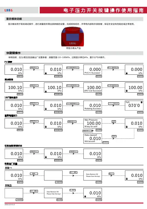
快捷键操作显示模块功能显示模块用于现场调试操作,进行测量前所需全部参数的设置,完成现场组态,并带有内部和外部按键,保证在安全和危险区域正常使用。
举例说明,压力/差压变送器出厂设置参数:测量范围-10~100kPa 过程显示单位置于大气中操作。
,,kPa 带显示表头产品详细操作说明第一路晶体管输出参数设置第二路晶体管输出参数设置显示隐藏参数方法一:详细操作说明参数表方法二:上述操作完成后,按键依次进入---参数设置,之后再次按下键进入隐藏参数设置M DisMod LRV URV Unit M 注:可用参数控制产品输出固定电流,从而确认产品电流输出电路是否正常,通过键修改固定电流值,并通过健确认即可。
1FixCOut S Z 注:可用参数手动控制两路晶体管状态,从而确认产品晶体管输出电路是否正常。
通过键修改晶体管输出状态,并通过键确认即可。
2FixTOut S ZDisplay module is used for field adjustment, all the parameters setting before measuring, complete site configuration.For example,Factory setting parameters: pressure range -10-100kPa, display unit kPa, operate in the atmosphere.Products with OLED displayAfter above operation, press M get into DisMod-LRV-Unit parameters setting,and press M again get into hidden parameters settingNote 1:Use FixCOut parameters to control fixed current ,to confirm whether current output is ok. Changing fixed current value by press S and confirm by Z.Note 2:Use FixTOut parameters to control 2 way PNP by mannual operation, to confirm whether PNP output is ok. Changing fixed current value by press S and confirm by Z.。
压力开关说明书产品作用:压力开关用于丈量流经管道的液体(水及氟化办理的制冷剂)或空气的压力状态,其典型应用是显示压力与控制压力。
●机械寿命≥10 万次 (参照值 JC 系列≥ 40 万次 )●设定值调整:当设定值精度要求不高时,可依据控制器标度尺和系统中的压力表进行调试,当设定值要求较高时 ,请用专用压力校验仪和精细压力表进行调试。
压力开关内部安装有一个高敏捷度的单刀双掷靠近开关。
开关可设定二个切换值,往常称为上限切换值和下限切换值。
详细调试方法:1.压力开关顶部的右边调理螺丝是直接调理上限切换值;2.压力开关顶部的左边调理螺丝是调理开关压差;3.它们的关系是:上限切换值 -开关压差 =下限切换值即:上限切换值能够直接在标尺上浮理下限切换值要经过1~ 3 操作来调理*比如:(高压保护器的用法)要求被控介质的压力保持在~ 0.8Mpa 之间。
1. 采用设定值范围在~ 1.0Mpa 的压力控制器( JC-210,HNS-210 )2. 旋动顶部右边的压力调理螺丝,使指针指示在标度尺的( 8kg 或 8bar)处,此值为上限切换值。
3. 旋动顶部左边的压力调理螺丝,使指针指示在标度尺的,下限切换值 =上限切换值 -开关压差 =0.8-0.3=0.5 ,此值为下限切换值。
4.将控制器的接线端子接入被控的电气回路。
请注意:①为公共接线。
③为常初步输出。
⑤为常闭端输出。
高压保护,请连结①⑤ ,在正常升压时,①-⑤接通(①-③不通)。
压力升到设定上限时即处,①-⑤不通(①-③接通)。
压力降落时,此时①-③接通,压力降落到下限设定点即处时。
又切换为①-⑤接通(① -③不通)。
降压停止,压力上涨,则自动循环。
5.接通电源,让被控介质(水、气)压力上涨。
请注意察看调正,使压力开关的设定值与压力表指示一致,(如压力升至上限设准时,开关还没有动作,即旋动压力调理螺丝,微调到切换动作,并再次重复考证一次)并作下限考证,过程同上。
Eaton CKD3400T56WEaton Series C electronic molded case circuit breaker, K-frame, CKD, Complete breaker, OPTIM 550, Electronic LSIG trip, Three-pole, 400A, 600 Vac, 250 Vdc, Without terminals, 50/60 Hz, 100% ratedGeneral specificationsEaton Series C electronic molded case circuit breakerCKD3400T56W 7821144039456 in6.25 in 5 in 12.05 lb Eaton Selling Policy 25-000, one (1) year from the date of installation of the Product or eighteen (18) months from the date of shipment of the Product, whichever occurs first.UL Listed Product NameCatalog NumberUPCProduct Length/Depth Product Height Product Width Product Weight WarrantyCertifications25 kAIC at 600 Vac35 kAIC at 480 VacK100% rated400 AThree-poleSeries COPTIM 550CKD415-600 Vac or 220-250 Vdc rear with left pigtail shunt 50 to 60 HzComplete breakerWithout terminals600 Vac, 250 VdcElectronic LSIG UL listed 100%-rated molded case circuit breakersApplication of Tap Rules to Molded Case Breaker Terminals Application of Multi-Wire Terminals for Molded Case Circuit BreakersCircuit breaker motor operators product aidPlug-in adapters for molded case circuit breakers product aid Power metering and monitoring with Modbus RTU product aid Motor protection circuit breakers product aidMulti-wire lugs product aidMOEM MCCB Product Selection GuideCurrent limiting Series C molded case circuit breakers product aid StrandAble terminals product aidK-Frame 310+ Molded-case circuit breakersBreaker service centersMolded case circuit breakers catalogEaton's Volume 4—Circuit ProtectionCircuit Breakers ExplainedCircuit breakers explainedEaton Specification Sheet - CKD3400T56WMOEM MCCB product selection guideSeries C G-Frame molded case circuit breakers time current curves Series C J-Frame molded case circuit breakers time current curvesF-Frame 310+ Molded-case circuit breakers 15-225ASeries C F-Frame molded case circuit breakersSelling Policy 25-000 - Distribution and Control Products and ServicesInterrupt ratingFrameRatingAmperage Rating Number of polesSeriesTypeCircuit breaker type Shunt tripFrequency ratingCircuit breaker frame type TerminalsVoltage ratingTrip Type Application notesBrochuresCatalogsMultimediaSpecifications and datasheets Warranty guidesEaton Corporation plc Eaton House30 Pembroke Road Dublin 4, Ireland © 2023 Eaton. All Rights Reserved. Eaton is a registered trademark.All other trademarks areproperty of their respectiveowners./socialmedia。
智能电动执行机构使用手册(CKD系列)目录一、产品概述 (1)二、主要技术指标 (1)三、执行机构的工作原理 (1)四、执行机构的显示 (2)五、执行机构的操作 (3)5.1手动操作 (3)5.2就地操作 (4)5.3远程操作 (4)六、执行机构的调试 (4)6.1 红外设定器说明 (4)6.2工作设定 (5)6.2.1进入菜单 (6)6.2.2调默认菜单 (6)6.2.3阀门基本状态设置 (6)6.2.4就地控制设置、远程开关量控制设置 (7)6.2.5触点设置 (7)6.2.6远程控制设置 (7)6.2.6.1远程模拟信号类型 (8)6.2.6.2远程其它设置 (8)七、安装步骤 (10)7.1安装信息 (10)7.2安装准备 (10)7.3现场安装 (11)典型安装调试流程图 (12)附录1:恒博智能执行机构菜单结构图 (13)1.1 基本设置 (15)1.2 附加设置 (18)1.3 ESD及安全设置 (20)1.4 时间及定时设置 (22)1.5 远程控制及反馈设置 (24)1.6 告警信息 (28)1.7 默认菜单调用/高级设置 (29)附录2:恒博智能执行机构远程控制连接图 (30)1.1 紧急保护-ESD电路的连接 (31)1.2 联锁控制 (31)1.3 二线控制 (32)1.4 三线控制 (32)1.5 四线控制 (33)1.6 远程阀位变送器 (33)1.7 远程阀门力矩变送器 (34)1.8 仅使用远程模拟量控制 (35)1.9 使用远程模拟量控制和远程开关量控制 (36)相关标准 (37)一、产品概述CKD系列智能电动执行机构是对阀门进行就地和远程电动控制的自动化设备,是由防爆电机、控制电路、减速机构等组成,为您提供了一种完美的机电一体化产品。
这些装置均密封在标准最高为IP68的双密封防水外壳内,使用手持式红外设定器即可对其进行非侵入性的快速设定、检查及查询。
该执行机构具有自动保护功能和隔爆功能,即使在危险区域也无需打开正在工作中的执行机构电气箱盖就可以进行调节、参数检查、故障诊断。
CKD系列全智能电动执行机构工程控制手册扬州恒春电子有限公司Yangzhou Hengchun Electronic Co.,Ltd前言欢迎您使用恒春CKD智能型电动执行机构!⏹关于本手册(1)本手册适用于CKD系列智能型电动执行机构。
(2)请确保完整阅读和理解本手册。
⏹安全使用注意事项(1)严格遵守使用手册是本电动执行器使用要求的一部分。
(2)本执行器的电气安装、维护及使用应按照国家相关安全性的法律、法规来进行,以适应现场安装。
(3)在电气作业期间,某些部件带有危及人身安全的电压。
电气系统或设备只能由熟练的电气技术员本人或在此类技术员控制和监视之下由经过培训的人员进行操作,并且必须遵守相应的电气工程规章。
(4)在操作过程中,电动执行器的温度会上升,并且表面温度可能会高于60℃。
请在触摸之前检查表面温度,以免灼伤。
(5)此图示的意义:警告!通过资格认证的操作人员必须熟知本手册中的所有安全警告和注意事项。
违反这些安全警告和注意事项可能造成严重的人身伤害及财产损失。
(6)在危险区域内,禁止用导电、导热体接触执行器,除非进行经特殊允许的工作,否则应切断电源,将执行器卸下并移到非危险区域进行维修或保养。
⏹保存(1)如果执行器不能立即安装,则应将它保存在一个干燥的地方,直到准备接线。
(2)如果执行器已安装好,但还没有接线,那么建议您将电缆入口的塑料塞换成缠有聚四氟乙烯的密封金属塞。
目录概述 (5)控制特性 (5)就地控制 (5)参数设置选项 (6)远程控制 (6)2 线制控制 (6)3 线制控制 (7)4 线制控制 (7)外部联锁控制 (7)ESD 紧急控制 (7)远程比例控制(可选) (7)Modbus总线控制(可选) (8)Profibus总线控制(可选) (8)HCBUS-1000双线通讯控制(可选) (8)信息显示与监测 (9)就地信息显示 (9)远程信息显示 (10)标准开关量输出 (10)监视继电器输出 (10)模拟量反馈输出- 阀门位置(可选) (11)自诊断信息和历史数据 (11)保护特性 (12)电机保护 (12)电源相位自动监测和纠正 (12)力矩保护 (12)双密封保护 (12)编码器故障保护 (12)阀门阻塞保护 (12)电机瞬时换向保护 (13)参数保护 (13)控制故障保护 (13)电气特性 (13)供电电源范围 (13)电机 (13)内部电源 (14)绝对位置检测模块(选配) (14)空间加热器(选配) (14)熔断保险 (14)独立的接线端子腔 (14)电气防护 (15)安全接地 (15)防护认证及技术参数 (15)外壳防护 (15)防爆和隔爆保护 (15)抗电磁干扰能力(EMC) (15)防腐保护 (15)工作制 (15)适应温度范围 (16)部分视图和结构特性 (16)机械结构和特性 (16)零部件材料和特性 (16)主传动链 (16)手轮操作 (16)非侵入式结构设计 (17)安装指南 (21)重要事项 (21)执行机构与阀门的连接 (21)驱动套与阀轴的连接 (21)使用手册 (24)电气连接 (24)接线端子盘定义 (24)电气接线图 (25)紧急保护-ESD电路的连接 (25)联锁信号接线 (26)远程控制回路接线 (27)操作指南 (32)就地模块 (32)就地模块包含下列内容: (32)图形显示和信息中心 (32)控制选钮和选择选钮 (32)LED 指示灯(发光二极管) (32)IrDA 红外接收操作 (33)参数设置操作 (33)执行器操作 (33)行程设置 (33)IrDA 红外控制方式 (34)LOCAL - 就地控制方式 (34)REMOTE – 远程开关量控制方式 (34)REMOTE – 远程模拟量控制方式 (34)手轮操作 (35)设置电动执行机构参数 (35)出厂默认设置 (35)进入参数设置模式 (35)输入密码 (35)主菜单 (36)更改参数设置 (36)调试向导 (36)设置菜单 (37)高级设置 (49)信息查询 (51)维护注意事项与常见的故障排除方法 (53)1 报警信息 (53)2 执行机构常见故障解疑 (53)3润滑及维护 (59)4防爆要点(隔爆型) (60)5维修时注意事项 (60)概述扬州恒春CKD智能型电动执行机构(以下简称执行机构),将先进的数字化阀门控制技术与经过多年考验的可靠性机械部件设计思路充分融合,并在吸收国外先进的技术基础上,依托恒春公司强大的研发团队自主研发、生产的机电一体化产品。
ckd比例阀接线说明书
阀编号1a,1b,2a,2b等中的数目字1, 2表示第几个连数,母a,b 表示a侧或b侧的线圈使用T30-T31配线方式的接插件通常称之为
D-Sub接插件。
广泛运用于FA元件和OA元件。
特别是25P型是计算机通讯机能采用的RS232C规格的指定接插件。
外集成的连数是面对
b侧线圈侧(单电控的场合盖子侧)从左按顺序设定。
3通阀单电控常闭常通自动回归型(压差弹簧回归)
3通阀双电控常闭常通自动保持型①PLC输出元件的信号配列有
必要与阀侧的信号配列相一致。
3通阀2个内置型常闭常通自动回归型(差弹簧回归)集成底板,阀搭载时的注意事项增加阀后,安装螺钉成为相当于M1.7的攻丝螺钉。
为了在集成底板上安装阀不需要进行螺钉的加工,因为在初次安装的时候,同时进行了攻丝。
外,在螺钉的前端,先涂上一些润滑油(CRC、平等),就能够顺利进行安装。
4通阀2位单电控自动回归型(压差弹簧回归
4通阀2位双电控自动保持型4通阀3位配管
①配管的拧紧固定以及重新调整配管时,必须在固定铲品之后方能进行。
外,在进行阀体侧配管时,或在阀体、盖侧进行配管时, 请
固定盖。
②在进行固定配管等时,请不要将配管的重和振动直接影响到阀。