力士乐方向阀样本
- 格式:pdf
- 大小:951.46 KB
- 文档页数:12

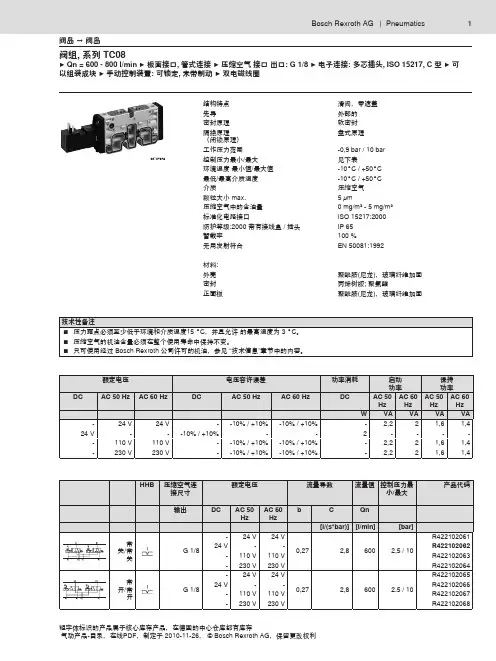
REXROTH力士乐换向阀的技术资料德国力士乐二位四通换向阀的结构特点:提动阀德国力士乐二位四通换向阀的密封原理:软密封在多线路导线板上的组装PRS-导线板工作压力范围1,5 bar / 10 bar *控制压力?最小/最大1,5 bar / 10 bar环境温度范围-15° C / +60 ° C *介质温度范围-15° C / +60 ° C *介质压缩空气颗粒大小max.50 ?m压缩空气中的含油量0 mg/m? - 1 mg/m?材料:外壳聚甲醛密封丙烯树胶螺纹管套聚甲醛*最大工作压力取决于环境温度。
以下数值适用:-15° C - 60° C: 1.5 - 8 bar的工作压力可行。
-15° C - 40° C: 1.5 - 10 bar的工作压力可行。
力士乐二位四通换向阀的技术备注:■不可超过最小控制压力,否则会导致故障电路和可能发生阀故障!■压力露点必须至少低于环境和介质温度15 ° C,并且允许的最高温度为 3 ° Co ■压缩空气的油含量必须在整个使用寿命中保持不变。
■只可使用经过AVENTICS公司许可的油,参见“技术信息”章节中的内容。
电磁换向阀4WEH22J7X/6EG24N9ETSK4+ 插头电磁换向阀4WEH32D6X/OF6EG24N9EK4电磁换向阀4WE 10 J33/CG24N9K4电磁换向阀4WE6D5X/AG24NK4电磁比例换向阀4WRA6W15-2X/G24K4/V电磁比例换向阀4WRZ16W8-150-7X/6EG24N9ETK4/M电液换向阀4WEH16D72/6EG24N9K4/B10D3电液换向阀4WEH16J72/6EG24N9K4电液换向阀4WEH16J72/6EG24N9S2K4/B08电液换向阀4WEH16Y72/6EG24N9K4/B10D3电液换向阀4WEH22HD76/6EG24N9K4电液换向阀4WEH32J63/6EG24N9S2K4B10比例阀4WRZ25W8-325-7X/6EG24N9EK4/M+Z4比例阀4WRZE25W8-325-7X/6EG24N9EK31/31/M+00021267比例换向阀4WRZE10E.85.7X/6EG24N9ETK31/F1M (带插头)比例换向阀4WRZE10E.85.7X/6EG24N9ETK31/F3M (带插头)比例换向阀4WRZE16E-100-7X/6EG24N9EK31/F1D3M比例换向阀4WRZE16W6-325L-70/6EG24N9K31/F1M 带插头电液比例阀4WRZE25W8-325-70/6EG24N9K31/F1M(带插头)比例阀4WRZE25W8-325-7X/6EG24N9EK31/31/M+00021267气缸822 240 008变量柱塞泵A10VSO71DR/31R-PPA12N00变量柱塞泵A4VSO125DR/22R-PPB13N00变量柱塞泵A4VSO125DR/31R-PPB13N00变量柱塞泵A4VSO250DR/30R-PPB13NO0变量柱塞泵A7VO55DR/63R-NPB01止回阀AB21-11/16-040-1-1X/V止回阀AB21-11/16-100-2-1X/V先导式溢流阀DB10-1-52/200博世力士乐Rexroth公司注册总部位于德国斯图加特,而营运总部及董事局总办事处则设于德国洛尔。
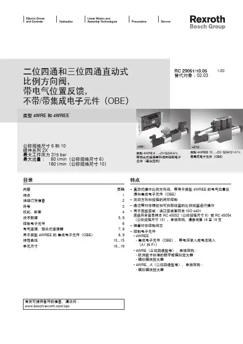
以组装成块 ▶ 手动控制装置: 可锁定, 未带制动 ▶ 双电磁线圈
00 37678结构特点滑阀,零遮盖
先导外部的
密封原理软密封
隔绝原理
(闭锁原理)
盘式原理
工作压力范围-0,9 bar / 0 bar
控制压力最小/最大见下表
环境温度 最小值/最大值- 0°C / +50°C
最低/最高介质温度- 0°C / +50°C
介质压缩空气
颗粒大小 max. 5 µm
压缩空气中的含油量0 mg/m³ - 5 mg/m³
标准化电路接口ISO 52 7:2000
防护等级:2000 带有接线盒 / 插头IP 65
暂载率 00 %
无用发射符合EN 5008 : 992
材料:
外壳聚酰胺(尼龙),玻璃纤维加固密封丙烯树胶; 聚氨酯
正面板
聚酰胺(尼龙),玻璃纤维加固
以组装成块 ▶ 手动控制装置: 可锁定, 未带制动 ▶ 双电磁线圈
以组装成块 ▶ 手动控制装置: 可锁定, 未带制动 ▶ 双电磁线圈
以组装成块 ▶ 手动控制装置: 可锁定, 未带制动 ▶ 双电磁线圈。

S型单向阀-力士乐液压阀样本————————————————————————————————作者:————————————————————————————————日期:S型单向阀特点S型单向阀的作用是使油液只能向一个方向流动而另一个方向止流,如图1-1所示。
—管式连接直通单向阀—有一个方向无泄漏的封闭—有五种开启压力—板式连接—插入式连接图1-1 S型单向阀功能说明S型单向阀阀芯的行程受到卡圈的限制,内装弹簧支承开闭行程并保持阀芯处于关闭状态。
S型单向阀为锥阀式结构,压力损失小,有五种开启压力和三种连接方式,管式和板式阀结构如图2-1和图2-2所示。
该阀主要用于泵的出口处,作背压阀和旁路阀用。
图2-1 板式阀结构图图2-2 板式阀结构图机能符号型号意义直通式K1 K2 K3规格6 301889 301896 301903规格8 301890 301897 301904规格10 301891 301898 301905规格15 301892 301899 301906规格20 301893 301900 301907规格25 301894 301901 301908规格30 301895 301902 301909直角式K1 K2 K3规格6 301910 301917 301924规格8 317701317702 317703规格10 301912 301919 301926规格15 317704 317705 317706规格20 301914 301921 301928规格25 301915 301922 301929规格30 301916 301923 301930例如:订6通径开启压力为0.05MPa的直通式插装阀,订货型号为S6K1-301889 技术参数液压介质矿物质液压油或磷酸酯液压油介质温度范围 (℃) -30~+80介质粘度范围 (mm2/S) 2.8~500工作压力 (MPa) 至31.5开启压力 (MPa)见特性曲线最大流量 (L/min)特性曲线(试验条件:在smmv/412=和℃50=t下测得)外形及连接尺寸(单位:mm)管式阀外型及连接尺寸:规格 6 8 10 15 20 25 30D1G1/4’’G3/8’’G1/2’’G3/4’’G1’’G11/4’’G11/2’’M14×1.5 M18×1.5 M22×1.5 M27×2 M33×2 M42×2 M48×2H1 22 28 34.5 41.5 53 69 75 L1 58 58 72 85 98 120 132 T1 12 12 14 16 18 20 22 S 19 24 30 36 46 60 65重量(kg)0.1 0.2 0.3 0.5 1 2 2.5 插入式阀外型及连接尺寸:NG 6 8 10 15 20 25 30D1H7 10 13 17 22 28 36 42D2 6 8 10 15 20 25 30D3H8 11 14 18 24 30 38 44D4 6 8 10 15 20 25 30行程 4 4 4 5 5 7 7L1 11.2 11.9 14.3 18 18.8 28.5 28.5L2 9.5 9.5 11.5 14.5 16 24.5 25L3 10 16 16 18 23 31 37L4 16.5 21.5 23.5 25.5 30 43 47.5L5 20.5 26.5 29.5 34 40.5 57.5 63.5L6 28.5 36.5 39.5 46 55.5 75.5 83.5重量kg 0.05 0.05 0.05 0.1 0.2 0.25 0.3NG 6 8 10 15 20 25 30D1H7 10 13 17 22 28 36 42D2 6 8 10 15 20 25 30D3H8 11 14 18 24 30 38 44行程 4 4 4 5 5 7 7L1 9.5 9.5 11.5 14.5 16 24.5 25L2 19 18 21 27 29 29 42L3 21.8 22.8 28.8 36.4 44 55 63L4 29.8 32.8 38.8 48.4 59 73 83L5 18 18 23 28 33 41 47重量kg 0.05 0.05 0.05 0.1 0.2 0.25 0.3 板式阀外型及连接尺寸:通径阀固定螺钉(GB70-85)A、B口O型圈10 4-M10×40-10.9 17.12×2.6220 4-M10×50-10.9 28.17×3.5330 4-M10×70-10.9 34.52×3.53NG B1 B2 L1 L2 L3 L4 H1 H210 85 66.7 78 42.9 17.8 - 66 2120 102 79.4 101 60.3 23 - 93.5 31.530 120 96.8 128 84.2 28 42.1 106.5 46注意事项:(1)液压系统用的介质必须经过过滤,过滤精度至少20μm;(2)液压系统用的油箱必须密封,并加空气过滤器;(3)固定螺栓请按样本中列的参数选用;(4)与阀连接的表面粗糙度要求为;(5)与阀连接的平面度要求为0.01/100mm。
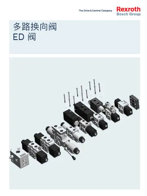
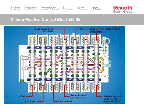
多路换向阀ED 阀2ED 多路阀 | | ED 多路阀 3博世力士乐推出“多路换向阀 — ED 多路阀手册”:根据具体应用,使用该手册可以简化多路阀元件选型。
我们的目标是制作一种非常方便查阅的材料(该材料不能代替产品样本)。
由于我们拥有完整的产品系列、清晰的型号体系以及各种可选项,该手册能有效指导用户选择所需的元件。
ED 多路阀可以替代传统的“六通换向阀”,同时 ED 多路阀元件可以“无限度”地进行组合,以满足用户的各种要求并提高设备的性能。
ED 多路阀手册的编写正是建立在这种 “ 片式 ED 多路阀”的理念基础之上。
ED 多路阀手册帮助用户完成多路阀元件的选型配置,构建控制执行机构(马达或油缸)的开关和比例电磁多路换向阀。
根据液压回路类别,参照该手册可以很容易地选择合适的多路阀元件以构建能够满足回路要求的系统。
手册中也包括了一些我们可以开发的适用于不同回路或应用的液压元件。
如果系统或应用对单联流量要求超过 80L/min,可以采用 ED 多路阀与 M4-12 / M4-15 阀组合使用的方案,构成“组合控制方案”。
应用:f 1. 随车起重机 f 2. 全路面起重机 f 3. 爬梯高空作业车 f 4. 车载高空作业车 f 5. 高空作业车 f 6. 叉车 f 7. 喷药车 f 8. 联合收割机 f 9. 伸缩臂叉车 f 10. 挖掘装载机 f 11. 挖掘机 f 12. 钻机 f 13. 垃圾车 f14. 扫地车简介应用及产品图片EDC 多路阀组合控制方案M4 + EDC + EDB 多路阀组合控制方案M4 + EDC + ED 多路阀EDD 多路阀图 1图 2从图 1 和图 2 中,我们可以看出 ED 多路阀与传统六通换向阀的区别。
对于传统控制阀(图 1),油泵通过阀的中位泄荷,而 ED 多路阀只有 4 个油口,因此需要专门的泄荷方法。
最常用的泄荷方法是采用如图 2 所示的 2 位 2 通电磁阀,或者使用逻辑元件。
A轴向柱塞单元名称型号编号版本第二册目录|行走机械液压 1/2⑤定量马达A2FM轴向柱塞定量马达A2FE插装式定量马达定量马达A4FM定量马达A10FM A10FE⑥变量马达轴向柱塞变量马达A6VMA6VE变量插装式马达双排量马达A10VM、插装式⑦常规要求及备件矿物油基液压油液用于轴向活塞件元件的环保型液压RC 91001RC 91008RC 91120RC 91172RC 91604RC 91606RC 91703RC 90220RC 90221A2FMA2FEA4FMA10FM/EA6VMA6VEA10VM/E07.0504.0504.0006.0605.0606.0506.0405.0301.02油HEES、HEPG和HETG使用HF油液的轴向柱塞元件万向轴连接法兰吸油管冲洗与补油阀SV功率阀LABVD平衡阀通用通轴驱动RC 90223RC 95001RC 95004RC 95512RC 95514RC 95522RC 9558111.9911.0002.9712.9809.9905.0312.05 SVLABVDfür A4VSA10VEA 轴向柱塞单元名称 型号 编号 版本⑧ 外啮合齿轮元件⑨ 径向柱塞马达⑩ 减速机2/2 行走机械液压 | 第二册目录外啮合齿轮泵F 型外啮合齿轮泵静音型外啮合齿轮马达液压马达(径向柱塞元件,多行程)径向柱塞马达(多行程)MCR 5型液压马达(径向柱塞元件,多行程)液压马达(径向柱塞元件,多行程)液压马达(径向柱塞元件,多行程)紧凑型静液压传动装置HYDROTRACGFT 用于定量或变量马达紧凑型静液压传动装置HYDROTRAC 带内置液压双速马达A10VT 回速减速机MOBILEX回转驱动MOBILEX GFB 带斜盘马达A10FD回转驱动MOBILEX GFB 适用于变桨和偏航调节卷扬减速机MOBILEX GFT-W 行星减速机REDULUSRC 10089RC 10095RC 14026RC 15205RC 15206RC 15207RC 15208RC 15209RC 77110RC 77111RC 77201RC 77204RC 76111RC 77502RC 76120AZPF AZPSAZMF, AZMN, AZMGMCR03MCR05MCR10MCR15MCR20GFT GFT 7-40GFB GFB GFB GFT-W GMH/GME08.0405.0401.0502.9806.0602.9810.9403.9507.0407.0405.0603.0109.0405.0410.05。
1/184/3 proportional directional control valve, without position control, with on-board electronics (OBE)Type 4WRBAE..E.. /..W..Nominal size (NG) 6, 10Unit series 2XMaximum working pressure P, A, B 315 bar, T 250 barNominal flow rate Q nom 18...32 l/min (NG6), 35...65 l/min (NG10)RE 29051/01.06Replaces: 09.05Overview of ContentsContents PageFeatures 1Ordering data 2Preferred types2Symbols 2Function, sectional diagram 3Accessories 4T echnical data5 to 7On-board trigger electronics 8 to 11Characteristic curves 12 to 15Unit dimensions16 and 17Features– D irectly controlled NG6 and NG10 valves with positive overlap and on-board electronics– A ctuated on both sides, standard symbols E, W – A djustable by means of the setpoint in the on-board electronics, see Characteristic Curves– V alves are preset at the factory, ramp is set to minimum ramp time and overlap (Q min at 0.8 V) to Q nom at 8 V– F or subplate attachment, mounting hole configuration NG6 to ISO 4401-03-02-0-94, NG10 to ISO 4401-05-04-0-94– S ubplates as per catalog sheet, RE 45053 for NG6, RE 45055 for NG10 (order separately)– P lug-in connector to DIN 43563-AM6, see catalog sheet RE 08008 (order separately)– D ata for the on-board trigger electronics• Complies with CE, EMC directives EN 61000-6-2: 2002-08 and EN 61000-6-3: 2002-08• U B = 24 V nom DC• Electrical connection 6P+PE • Signal actuation– Standard 0...±10 V (A1) – Version 2...12...20 mA (F1)• Valve curves calibrated at the factoryOrdering dataFunction, sectional diagramGeneralDirectly operated type 4WRBAE 4/3 proportional directional control valves without position control, with on-board electronics, are available in nominal sizes 6 and 10.Hysteresis is < 6 % for the NG6 and < 8 % for the NG10.The valve electronics are integrated and are preset during valve testing. The operating limits are largely determined by the available magnetic force, see characteristic curves.Basic principleT o adjust the oil flow rate, a setpoint is set in the valve elec-tronics. Based on the polarity and magnitude of this setpoint, the electronics control the solenoid coil “a” or “b” with thea ppropriate amount of magnetic force. The proportional sole-noid converts the current to a mechanical force, with which an armature plunger acts on a spool to push against the spring. If the magnetic force and the spring force are the same, this produces a spool position in conformity with the spring characteristic curve. If the drop in pressure is minimal (< 30 bar) the throttling function takes effect, if the pressure drop is greater, the operating limits (see characteristic curves) must be observed.The pressure drop at the valve is reliably limited by the use of an external pressure compensator with shuttle valve.Manual auxiliary overrideNG6Regelmagnet RegelmagnetManual auxiliary overrideValve bodySolenoid “a”Solenoid “b”Electronics(see page 4)Manual auxiliary overrideManual auxiliary overrideValve bodySolenoid “a”Solenoid “b”Electronics(see page 4)NG10Testing and service equipmentT est box type VT-PE-TB3, see RE 30065Measuring adapter 6PE+PE type VT-PA-2, see RE 30068AccessoriesTypeMaterial Number (4x) f ISO 4762-M5x30-10.9Cheese-head bolts NG6 2 910 151 166(4x) f ISO 4762-M6x35-10.9Cheese-head bolts NG10 2 910 151 207*Plug-in connector 6P+PE, see also RE 08008KS 1 834 482 022KS 1 834 482 026MS 1 834 482 023MS1 834 482 024KS 90°1 834 484 252Technical dataPort P, A, B: 315Port T: 250* N ominal flowThis is always based on a pressure differential of ∆p = 5 bar at the throttling point.Where other pressure differentials are involved, the flow is calculated according to the following formula: ∆p XQ x = Q nom ·Ί 5However, the operating limits must be borne in mind. If they are exceeded, the ensuing flow forces lead to un-controllable spool movements. Pressure compensators are used to reliably limit ∆p .Ϲ 6 Ϲ 8 Ϲ 3 Ϲ 5 50901) T he purity classes stated for the components must becomplied with in hydraulic systems. Effective filtration prevents problems and also extends the service life of components.For a selection of filters, see catalog sheets RE 50070, RE 50076 and RE 50081.Technical dataNote:Power supply 40 V DCnom, max. 31 V DC, max. ripple 2 V DC.Valve in center position:Version 0...±10 Vat UD –EՅ ±0.2 VVersion 4...20 mAat ID –E= 12 mAՅ ±0.4 mAConnectionFor electrical data, see page 6 and Operating Instructions 1 819 929 083Technical notes for the cableDesign: – Multi-wire cable – Extra-finely stranded wire to VDE 0295, Class 6 – Safety earth conductor, green/yellow – Cu braided shield Typ: – e.g. Ölflex-FD 855 CP (from Lappkabel company)No. of wires: – Determined by type of valve, plug type and signal assignment Cable Ø: – 0.75 mm 2 up to 20 m long – 1.0 mm 2 up to 40 m long Outside Ø: – 9.4...11.8 mm – Pg11– 12.7...13.5 mm – Pg16ImportantPower supply 24 V DC nom ,if voltage drops below 18 V DC, rapid shutdown resembling “Enable OFF” takes place internally.In addition, with the “mA signal” version:I D–E м 3 mA – valve is activeI D–E Ϲ 2 mA – valve is deactivated.Electrical signals (e.g. actual values) emitted via the trigger electronics must not be used to shut down safety-relevantm achine functions!(Also see European Standard, “T echnical Safety Requirements for Fluid-Powered Systems and Components – Hydraulics”, EN 982).On-board trigger electronics Circuit diagram/pin assignment0...±10 VVersion A1: UD –EOn-board trigger electronics Circuit diagram/pin assignment4...12...20 mAVersion F1: ID –EOn-board trigger electronicsR sh = 200 ΩIINOUTPin assignmentVersion A1: U D – E 0...±10 V R i = 100 k ΩPin assignment 6P+PEVersion F1: I D – E 4...12...20 mA R sh = 200 ΩOn-board trigger electronicsValve adjustment4/3 proportional directional control valves with on-board electronics without position control are preset at the factory.Valves without position control are subject to broader toler-ances than valves with position control. Therefore, the design of the valves allows them to be adjusted when installed in the machine.First, slacken the screws, then open the lid to set the para-meters using potentiometers.NoteThe characteristic curve and dither frequency are factory-set. We recommend that you only alter P2...P6 if absolutely necessary.The P1 ramp is adjustable:0.05...5 s for 0.8...10 V, or 12.6...20 mA signal change.For other possibilities, see valve curves.Adjusting the electronicsFirst, slacken the screws,then open the lid to set the parameters.Version: U D – E = 0...±10 V Version: I D – E = 4...12...20 mACharacteristic curves NG6 (measured with HLP 46,oil= 40 °C ±5 °C)UD–E[V]1)ID–E[mA]2)UD–E[V]1)ID–E[mA]2) Qnom= 18 l/minQnom= 32 l/minSee page 11for adjusting the electronics1) Version: UE= 0...±10 V2) Version: IE= 4...12...20 mA= 40 °C ±5 °C) Characteristic curves NG6 (measured with HLP 46,oilOperating limitsCharacteristic curves NG10 (measured with HLP 46,oil= 40 °C ±5 °C)Qnom= 35 l/minSee page 11for adjusting the electronics1) Version: UE = 0...±10 V2) Version: IE = 4...12...20 mAQ[I/min]I D–E[mA]2)U D–E[V]1)–Q[I/min]I D–E[mA]2)U D–E[V]1)–Hinweis/Remark/Note:Qnom= 65 l/min= 40 °C ±5 °C) Characteristic curves NG10 (measured with HLP 46,oilOperating limitsUnit dimensions NG6 (nominal dimensions in mm)Required surface quality of mating componentMounting hole configuration: NG6 (ISO 4401-03-02-0-94)For subplates, see catalog sheet RE 450531) Deviates from standard 2) T hread depth:Ferrous metal 1.5 x ØNon-ferrous 2 x ØNot included in scope of deliveryLED for solenoid B LED for solenoid AUnit dimensions NG10 (nominal dimensions in mm)Not included in scope of deliveryRequired surface quality of mating componentMounting hole configuration: NG10 (ISO 4401-05-04-0-94)For subplates, see catalog sheet RE 450551) Deviates from standard 2) T hread depth:Ferrous metal 1.5 x Ø*Non-ferrous 2 x Ø* NG10 min. 10.5 mmLED for solenoid B LED for solenoid ABosch Rexroth AGHydraulicsZum Eisengießer 197816 Lohr am Main, GermanyT elefon +49 (0) 93 52 / 18-0T elefax +49 (0) 93 52 / 18-23 58 documentation@boschrexroth.de www.boschrexroth.de © This document, as well as the data, specifications and other information set forth in it, are the exclusive property of Bosch Rexroth AG. It may not be reproduced or given to third parties without its consent.The data specified above only serve to describe the product. No state-ments concerning a certain condition or suitability for a certain application can be derived from our information. The information given does not release the user from the obligation of own judgement and verification. It must be remembered that our products are subject to a natural process of wear and aging.NotesBosch Rexroth AGHydraulicsZum Eisengießer 197816 Lohr am Main, GermanyT elefon +49 (0) 93 52 / 18-0T elefax +49 (0) 93 52 / 18-23 58 documentation@boschrexroth.de www.boschrexroth.de © This document, as well as the data, specifications and other information set forth in it, are the exclusive property of Bosch Rexroth AG. It may not be reproduced or given to third parties without its consent.The data specified above only serve to describe the product. No state-ments concerning a certain condition or suitability for a certain application can be derived from our information. The information given does not release the user from the obligation of own judgement and verification. It must be remembered that our products are subject to a natural process of wear and aging.NotesBosch Rexroth AGHydraulicsZum Eisengießer 197816 Lohr am Main, GermanyT elefon +49 (0) 93 52 / 18-0T elefax +49 (0) 93 52 / 18-23 58 documentation@boschrexroth.de www.boschrexroth.de © This document, as well as the data, specifications and other information set forth in it, are the exclusive property of Bosch Rexroth AG. It may not be reproduced or given to third parties without its consent.The data specified above only serve to describe the product. No state-ments concerning a certain condition or suitability for a certain application can be derived from our information. The information given does not release the user from the obligation of own judgement and verification. It must be remembered that our products are subject to a natural process of wear and aging.Notes。
二位四通换向阀产品样本公司专业经销德国原装力士乐,在力士乐液压泵、液压阀、伺服及比例阀、放大板等产品具有很强的竞争优势,优势产品型号有、、、、、系列阀,、、系列柱塞泵,、液压马达,系列压力继电器伺服驱动器。
力士乐电磁换向阀是利用电磁铁推动阀芯来控制液流方向的。
采用电磁换向阀可以使操作轻便,容易实现自动化操作,因此应用极广。
电磁换向阀只是采用电磁铁来操纵滑阀阀芯运动,而阀芯的结构及型式可以是各种各样的,所以电磁滑阀可以是二位二通、二位三通、二位四通、三位四通和三位五通等多种型式。
一般二位阀用一个电磁铁,三位阀需用两个电磁铁。
国际液压市埸一直处于世界领先的位置。
力士乐换向阀力士乐换向阀换向座阀:,,,,换向滑阀:,,,,,,,,,,,,,,,力士乐压力阀溢流阀:,,,,,,,减压阀:,,,,,,力士乐流量阀节流阀:,通径,流量约,。
,通径,流量约,。
流量控制阀:,通流量控制阀,(插装阀),通径。
,通流量控制阀。
,流量控制阀(叠加板阀)。
力士乐比例阀比例换向阀:,,,,,,,。
比例压力阀:比例溢流阀:,,,,,。
比例减压阀:,,,。
比例流量阀:,,,二位四通换向阀是采用控制阀体内的启闭件的开度来调节介质的流量,将介质的压力降低,同时借助阀后压力的作用调节启闭件的开度,使阀后压力保持在一定范围内,并在阀体内或阀后喷入冷却水,将介质的温度降低,这种阀门称为减压减温阀。
该阀的特点,是在进口压力不断变化的情况下,保持出口听压力和温度值在一定的范围内。
减压阀按结构形式可分为薄膜式、弹簧薄膜式、活塞式、杠杆式和波纹管式;按阀座数目可人为单座式和双座式;按阀瓣的位置不同可分为正作用式和反作用式。
先导式减压阀当减压阀的输出压力较高或通径较大时,用调压弹簧直接调压,则弹簧刚度必然过大,流量变化时,输出压力波动较大,阀的结构尺寸也将增大。
为了克服这些缺点,可采用先导式减压阀。
先导式减压阀的工作原理与直动式的基本相同。
二位四通换向阀用在受压设备、容器或管路上,作为超压保护装置。