AngioJet产品介绍说课讲解
- 格式:ppt
- 大小:11.40 MB
- 文档页数:20


Page 1©2011 Whelen Engineering Company Inc.Form No.14536A (071112)A u t o m o t i v e : S i r e n s /S w i t c h e sFor warranty information regarding this product, visit /warrantyDANGER! Sirens produce extremely loud emergency warning tones! Exposure to these tones without proper and adequate hearing protection, could cause ear damage and/or hearing loss! The Occupational Safety & Health Administration () provides information necessary to determine safe exposure times in Occupational Noise Exposure Section 1910.95. Until you have determined the safe exposure times for your specific application,operators and anyone else in the immediate vicinity should be required to wear an approved hearing protection device. Failure to follow this recommendation could cause hearing loss!•Proper installation of this product requires the installer to have a good understanding of automotive electronics, systems and procedures.•Whelen Engineering requires the use of waterproof butt splices and/or connectors if that connector could be exposed to moisture.•Any holes, either created or utilized by this product, should be made both air- and watertight using a sealant recommended by your vehicle manufacturer.•Failure to use specified installation parts and/or hardware will void the product warranty.•If mounting this product requires drilling holes, the installer MUST be sure that no vehicle components or other vital parts could be damaged by the drilling process. Check both sides of the mounting surface before drilling begins. Also de-burr the holes and remove any metal shards or remnants. Install grommets into all wire passage holes.•If this manual states that this product may be mounted with suction cups, magnets, tape or Velcro®, clean the mounting surface with a 50/50 mix of isopropyl alcohol and water and dry thoroughly.•Do not install this product or route any wires in the deployment area of your air bag. Equipment mounted or located in the air bag deployment area will damage or reduce the effectiveness of the air bag, or become a projectile that could cause serious personal injury or death. Refer to your vehicle owner’s manual for the air bag deployment area. The User/Installer assumes full responsibility to determine proper mounting location, based on providing ultimate safety to all passengers inside the vehicle.•For this product to operate at optimum efficiency, a good electrical connection to chassis ground must be made. The recommended procedure requires the product ground wire to be connected directly to the NEGATIVE (-) battery post (this does not include products that use cigar power cords).•If this product uses a remote device for activation or control, make sure that this device is located in an area that allows both the vehicle and the device to be operated safely in any driving condition.•It is recommended that these instructions be stored in a safe place and referred to when performing maintenance and/or reinstallation of this product.•FAILURE TO FOLLOW THESE SAFETY PRECAUTIONS AND INSTRUCTIONS COULD RESULT IN DAMAGE TO THE PRODUCT OR VEHICLE AND/OR SERIOUS INJURY TO YOU AND YOUR PASSENGERS!CAUTIONLoud siren noise can cause hearing damage and/or loss.Refer to OSHA Section 1910.95prior to putting ANY siren into service!Wear Protection!ACTIVATION OF THIS SIREN MAY DAMAGE UNPROTECTED EARS!Warnings to InstallersWhelen’s emergency vehicle warning devices must be properly mounted and wired in order to be effective and safe. Read and follow all of Whelen’s written instructions when installing or using this device. Emergency vehicles are often operated under high speed stressful conditions which must be accounted for when installing all emergency warning devices. Controls should be placed within convenient reach of the operator so that they can operate the system without taking their eyes off the roadway. Emergency warning devices can require high electrical voltages and/or currents. Properly protect and use caution around live electrical connections.Grounding or shorting of electrical connections can cause high current arcing, which can cause personal injury and/or vehicle damage, including fire. Many electronic devices used in emergency vehicles can create or be affected by electromagnetic interference. Therefore, after installation of any electronic device it is necessary to test all electronic equipment simultaneously to insure that they operate free of interference from other components within the vehicle. Never power emergency warning equipment from the same circuit or share the same grounding circuit with radio communication equipment. All devices should be mounted in accordance with the manufacturer’s instructions and securely fastened to vehicle elements of sufficient strength to withstand the forces applied to the device. Driver and/or passenger air bags (SRS) will affect the way equipment should be mounted. This device should be mounted by permanent installation and within the zones specified by the vehicle manufacturer, if any. Any device mounted in the deployment area of an air bag will damage or reduce the effectiveness of the air bag and may damage or dislodge the device. Installer must be sure that this device, its mounting hardware and electrical supply wiring does not interfere with the air bag or the SRS wiring or sensors. Mounting the unit inside the vehicle by a method other than permanent installation is not recommended as unit may become dislodged during swerving; sudden braking or collision. Failure to follow instructions can result in personal injury. Whelen assumes no liability for any loss resulting from the use of this warning device. PROPER INSTALLATION COMBINED WITH OPERATOR TRAINING IN THE PROPER USE OF EMERGENCY WARNING DEVICES IS ESSENTIAL TO INSURE THE SAFETY OF EMERGENCY PERSONNEL AND THE PUBLIC.Warnings to UsersWhelen’s emergency vehicle warning devices are intended to alert other operators and pedestrians to the presence and operation of emergency vehicles and personnel. However, the use of this or any other Whelen emergency warning device does not guarantee that you will have the right-of-way or that other drivers and pedestrians will properly heed an emergency warning signal. Never assume you have the right-of-way. It is your responsibility to proceed safely before entering an intersection, driving against traffic, responding at a high rate of speed, or walking on or around traffic lanes. Emergency vehicle warning devices should be tested on a daily basis to ensure that they operate properly. When in actual use, the operator must ensure that both visual and audible warnings are not blocked by vehicle components (i.e.: open trunks or compartment doors), people, vehicles, or other obstructions. It is the user’s responsibility to understand and obey all laws regarding emergency warning devices. The user should be familiar with all applicable laws and regulations prior to the use of any emergency vehicle warning device. Whelen’s audible warning devices are designed to project sound in a forward direction away from the vehicle occupants. However, because sustained periodic exposure to loud sounds can cause hearing loss, all audible warning devices should be installed and operated in accordance with the standards established by the National Fire Protection Association.Safety FirstThis document provides all the necessary information to allow your Whelen product to be properly and safely installed. Before beginning the installation and/or operation of your new product, the installation technician and operator must read this manual completely. Important information is contained herein that could prevent serious injury or damage.Installation Guide:Howler™ Siren Speaker BracketModel: HWLFT112010-2015 Ford Taurus Interceptor51 Winthrop RoadChester, Connecticut 06412-0684Phone: (860) 526-9504Internet: Sales e-mail: autosale@Customer Service e-mail: custserv@®ENGINEERING COMPANY INC.IMPORTANT! READ THESE WARNINGS BEFORE CONTINUING!The Howler™ Supplemental Siren was designed for use in high-risk areas such as an intersection. It is not intended to be, nor should be operated as a replacement or alternative to the vehicle’s primary siren.The low-frequency tones of the Howler demonstrate significantly different audio characteristics as compared to those of a traditional higher-frequency siren. While the low-frequency tones are better able to penetrate other vehicles, thus alerting drivers to the presence of the responding emergency vehicle, these tones may also penetrate into the responding vehicle itself. This could potentially expose the operator to increased noise levels.To help eliminate overexposure, the Howler siren has been designed with a built-in timing circuit. The Occupational Safety & Health Administration (OSHA) () provides information necessary to determine safe exposure times in Noise and Hearing Conservation, Section 1910.95(Occupational Noise Exposure). Until you have determined the safe exposure times for your specific application, this siren should be configured for the minimum operating time and operators should be required to use an approved hearing protection device. FAILURE TO FOLLOW THIS RECOMMENDATION COULD CAUSE HEARING LOSS!IMPORTANT: It is the responsibility of the installation technician to make sure that the installation and operation of this product will not interfere with or compromise the operation or efficiency of any vehicle equipment!Installation:IMPORTANT: The slotted holes in the siren speaker must face toward the road after mounting for proper drainage.1.Bracket mounts to vehicle frame behind front fender on driver side (Fig. 1). Secure Howler siren speaker to Lower Support Bracket using supplied 5/16 X 1” Hex Head Sheet Metal Screws (Fig. 2).2.Loosely secure Lower Support Bracket (around vehicle frame) to Upper Support Bracket using supplied 5/16 Flat Washers, 5/16 Split Lock Washers and 5/16 - 18 X 1 Hex Head Bolts (Fig. 3).3.Line holes in the frame up to circular raised area on both support brackets and install 3/8 - 16 X 4” Hex Head Bolt, 3/8” Flat Washer wires away from any excessive heat or from any vehicle。
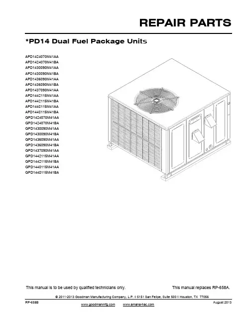
REPAIR PARTSRP-658BThis manual is to be used by qualified technicians only.This manual replaces RP-658A.© 2011-2013 Goodman Manufacturing Company, L.P. ◊ 5151 San Felipe, Suite 500 ◊ Houston, TX 77056August 2013*PD14 Dual Fuel Package UnitsAPD1424070M41AA APD1424070M41BA APD1430090M41AA APD1430090M41BA APD1436090M41AA APD1436090M41BA APD1437090M41AA APD1442115M41AA APD1442115M41BA APD1448115M41AA APD1448115M41BA GPD1424070M41AA GPD1424070M41BA GPD1430090M41AA GPD1430090M41BA GPD1436090M41AA GPD1436090M41BA GPD1437090M41AA GPD1442115M41AA GPD1442115M41BA GPD1448115M41AA GPD1448115M41BAImportant Information For assistance within the U.S.A. contact:Goodman Company, L.P.For assistance outside the U.S.A. contact:IndexFunctional Parts List Rev B: Addition of 3 Ton models with increased efficiencyIllustration and Parts......................................................................................................................................................................................................Views shown are for parts illustrations only, not servicing procedures.AR - As Required NA - Not Available NS - Not Shown00000000 - See NoteQTY - Quantity Example (QTY 3) (If Quantity not shown, Quantity = 1)M - Model Example (M1) (If M Code not shown, then part is used on all Models)Text Codes:ExampleM1 - Model#1 M2 - Model#2 M3 - Model#3Expanded Model Nomenclature:Goodman Manufacturing Company, L.P. is not responsible for personal injury or property damage resulting from improper service. Review all service information before beginning repairs.Warranty service must be performed by an authorized technician, using authorized factory parts. If service is required after the warranty expires, Goodman Manufacturing Company, L.P. also recommends contacting an authorized technician and using authorized factory parts.Goodman Manufacturing Company, L.P. reserves the right to discontinue, or change at any time, specifications or designs without notice or without incurring obligations. 2Consumer Affairs DepartmentGoodman Manufacturing Company, L.P.7401 Security Way Houston, Texas 77040877-254-4729-Telephone 713-863-2382-FacsimileInternational DivisionGoodman Manufacturing Company, L.P.7401 Security Way Houston, Texas 77040713-861-2500-Telephone 713-863-2382-Facsimileg g 4 - 153RP-658BFunctional Parts PartNo:Description:0130M0002524V RELAY10735102BECKETT BURNER (QTY A/R)D6723303S BLOWER WHEEL (M3, M4, M5, M6, M7, M14,M15, M16, M17, M18)B1368058BLOWER WHEEL 10 X 8 (M1, M2, M12, M13) B1368000BLOWER WHEEL 11 X 10 (M8, M9, M10, M11,M19, M20, M21, M22)CAP050400440RT CAPACITOR 5/40/440V (M1, M2, M3, M4, M12,M13, M14, M15)CAP050450440RT CAPACITOR 5/45/440V (M5, M6, M7, M8, M9,M10, M11, M16, M17, M18, M19, M20, M21,M22)ZP21K5EPFV130COMP,21300,208/230/60/1 (M1, M2, M12, M13) ZP34K5EPFV130COMP,34500,208/230/60/1 (M8, M9, M19, M20) ZP25K5EPFV130COMPRESSOR 25200, 208/230/60/1 (M3, M4,M14, M15)ZP29K5EPFV130COMPRESSOR 29000, 208/230/60/1 (M7, M18) ZP31K5EPFV130COMPRESSOR 31100, 208/230/60/1 (M5, M6,M16, M17)ZP39K5EPFV130COMPRESSOR 39000, 208/230/60/1 (M10,M11, M21, M22)0131M00429COND MOTOR 1/4 HP, 1 SP, 6 PL (M8, M9,M10, M11, M19, M20, M21, M22)0131M00061COND MOTOR 1/4 HP, 1 SP, 8 PL (M3, M4,M5, M6, M7, M14, M15, M16, M17, M18)0131M00009P COND MOTOR 1/6 HP, 1 SP, 8 PL (M1, M2,M12, M13)CONT1P025024V CONTACTOR 25 AMP, 1P, 24V (M1, M2, M3,M4, M5, M6, M7, M12, M13, M14, M15, M16,M17, M18)CONT1P030024V CONTACTOR 30 AMP, 1P, 24V (M8, M9, M10,M11, M19, M20, M21, M22)0230G00005CRANKCASE HEATER SWITCH (M8, M9,M19, M20)B1086773FAN BLADE 22" (M1, M2, M12, M13)0150G00003FAN BLADE SWEPT-WING (M8, M9, M10,M11, M19, M20, M21, M22)0150G00002FAN BLADE SWEPT-WING (M3, M4, M5, M6,M7, M14, M15, M16, M17, M18)0130F00010FLAME SENSOR0151F00000P GAS VALVE - WHITE-RODGERS 2-STAGE 0163R00003HEATER, CRANKCASE 230V 40W (M8, M9,M19, M20)0130M00074HIGH PRESSURE SWITCH0130F00014IGNITOR10728344LIMIT SWITCH (M8, M9, M10, M11, M19, M20,M21, M22)10728343LIMIT SWITCH (M1, M2, M3, M4, M5, M6, M7,M12, M13, M14, M15, M16, M17, M18)0130M00075LOW PRESSURE SWITCH10123529MANUAL RESET LIMIT0131M00361MOTOR - 3/4 HP PROGRAMMED SELE (M10,M21)0131M00351MOTOR - 3/4 HP PROGRAMMED SELE (M8,M19)0131M00379MOTOR-1/2 HP PROGRAMMED SELEC (M3,M14)0131M00378MOTOR-1/2 HP PROGRAMMED SELEC (M5,M16)0131M00364MOTOR-1/2 HP PROGRAMMED SELEC (M1,M12)PCBDM133PCB, DEFROST CONTROLPCBAG127PCB, IGNITION, DSI, 2 STG 11112501PRESSURE SWITCH0131M00594PROGRAMMED MOTOR (M7, M18)0131M00434PROGRAMMED MOTOR (M2, M13)0131M00435PROGRAMMED MOTOR (M4, M15)0131M00436PROGRAMMED MOTOR (M6, M17)0131M00441PROGRAMMED MOTOR (M11, M22)0131M00440PROGRAMMED MOTOR (M9, M20)0151M00019REVERSING VALVE (M1, M2, M3, M4, M7,M12, M13, M14, M15, M18)0151M00021REVERSING VALVE (M5, M6, M8, M9, M10,M11, M16, M17, M19, M20, M21, M22)0130M00138TRANSFORMER, 208/230, 24VExpanded Model NomenclatureM1 - APD1424070M41AAM2 - APD1424070M41BAM3 - APD1430090M41AAM4 - APD1430090M41BAM5 - APD1436090M41AAM6 - APD1436090M41BAM7 - APD1437090M41AAM8 - APD1442115M41AAM9 - APD1442115M41BAM10 - APD1448115M41AAM11 - APD1448115M41BAM12 - GPD1424070M41AAM13 - GPD1424070M41BAM14 - GPD1430090M41AAM15 - GPD1430090M41BAM16 - GPD1436090M41AAM17 - GPD1436090M41BAM18 - GPD1437090M41AAM19 - GPD1442115M41AAM20 - GPD1442115M41BAM21 - GPD1448115M41AAM22 - GPD1448115M41BA3RP-658B Top Panel/Fan/Cabinet 4RP-658BTop Panel/Fan/CabinetRef.No:Part No:Description:Ref.No:Part No:Description:Image 1:FAN BLADE 22" (M1, M2, M12, M13)B108677311FAN BLADE SWEPT-WING (M3, M4, M5, M6, M7, M14, M15, M16, M17, M18)0150G0000211FAN BLADE SWEPT-WING (M8, M9, M10, M11, M19, M20, M21, M22)0150G0000311COND MOTOR 1/4 HP, 1 SP, 6 PL (M8, M9, M10, M11, M19, M20, M21, M22)0131M0042921COND MOTOR 1/4 HP, 1 SP, 8 PL (M3, M4, M5, M6, M7, M14, M15, M16, M17, M18)0131M0006121COND MOTOR 1/6 HP, 1 SP, 8 PL (M1, M2, M12, M13)0131M00009P 21GRILLE-FAN 0152G0000231PNL, TOP, PNT 0121G00156PDG 41SMALL SCREW (QTY 6)M022181751ACORN NUT 5/16 HEX BLACK (QTY 4)0163M00006P 61BLOWER DOOR 32" (M1, M2, M3, M4, M5, M6, M7, M12, M13, M14, M15, M16, M17, M18)20464801PDG 71BLOWER DOOR 40" (M8, M9, M10, M11, M19, M20, M21, M22)20464806PDG 71DOOR-EVAP/CONTROL 32 W/PAINT (M1, M2, M3, M4, M5, M6, M7, M12, M13, M14, M15, M16, M17, M18)20464802PDG81EVAP/CONTROL DOOR 40" (M8, M9, M10, M11, M19, M20, M21, M22)20464807PDG 81DOOR-HT EXCHANGE 32 (M1, M2, M3, M4, M5, M6, M7, M12, M13, M14, M15, M16, M17, M18)0121G00526DG 91DOOR-HT EXCHANGE 38 (M8, M9, M10, M11, M19, M20, M21, M22)0121G00527DG 91DOOR-COMPRESSOR 32 W/PAINT (M1, M2, M3, M4, M5, M6, M7, M12, M13, M14, M15, M16, M17, M18)20464804PDG101DOOR-COMPRESSOR 40 W/PAINT (M8, M9, M10, M11, M19, M20, M21, M22)20464809PDG 101LOUVERED PANEL, COND SIDE 32" (M12, M13, M14, M15, M16, M17, M18)20467701PDG 111LOUVERED PANEL, COND SIDE 32" (M1, M2, M3, M4, M5, M6, M7)20467701PLG 111LOUVERED PANEL, COND SIDE 40" (M19, M20, M21, M22)20467702PDG 111LOUVERED PANEL, COND SIDE 40" (M8, M9, M10, M11)20467702PLG 111UTILITY PANEL 32" (M1, M2, M3, M4, M5, M6, M7, M12, M13, M14, M15, M16, M17, M18)20466101PDG 121UTILITY PANEL 40" (M8, M9, M10, M11, M19, M20, M21, M22)20466102PDG 121PNL, DUCT, GAS 32.5" (M1, M2, M3, M4, M5, M6, M7, M12, M13, M14, M15, M16, M17, M18)0121G00442DG 131PNL, DUCT, GAS 40" (M8, M9, M10, M11, M19, M20, M21, M22)0121G00443DG 131SUPPORT POST 32" (M1, M2, M3, M4, M5, M6, M7, M12, M13, M14, M15, M16, M17, M18)0121G00460141SUPPORT POST 40" (M8, M9, M10, M11, M19, M20, M21, M22)0121G00462141LOUVERED PANEL, COND SIDE 32" (M12, M13, M14, M15, M16, M17, M18)20464401PDG 161LOUVERED PANEL, COND SIDE 32" (M1, M2, M3, M4, M5, M6, M7)20464401PLG 161LOUVERED PANEL, COND SIDE 40" (M19, M20, M21, M22)20464402PDG 161LOUVERED PANEL, COND SIDE 40" (M8, M9, M10, M11)20464402PLG 161BASE PAN RAIL (QTY 2)0121G00290181CORNER POST-COMP END 32" (M1, M2, M3, M4, M5, M6, M7, M12, M13, M14, M15, M16, M17, M18)20464201PDG251Image 1:CORNER POST-COMP END 40" (M8, M9, M10, M11, M19, M20, M21, M22)20464202PDG 251CORNER POST-HAIRPIN END 32" (M1, M2, M3, M4, M5, M6, M7, M12, M13, M14, M15, M16, M17, M18)20464301PDG261CORNER POST-HAIRPIN END 40" (M8, M9, M10, M11, M19, M20, M21, M22)20464302PDG 261FLUE HOOD (QTY 2)0121G00323271FLUE HOOD-LOWER 0121G00190281SCREEN-FLUE HOOD 20472601291GAS LINE GROMMET B1910012301ACCESS FITTING (QTY 2)B1373315NS CAP WITH O-RING (QTY 2)0163M00175NS FLUE HOOD ASSY 0270G00070NS PVC CONDUIT 8.25"177********F NS WASHER, BLACK (.50 OD .218ID) (QTY 4)0163M00005P NS WIRE HARNESS, FAN MOTOR (M1, M2, M8, M9, M10, M11, M12, M13, M19, M20, M21, M22)0259G00106NS WIRE HARNESS, FAN MOTOR (M3, M4, M5, M6, M7, M14, M15, M16, M17, M18)0259G00107NSExpanded Model Nomenclature M1 - APD1424070M41AA M2 - APD1424070M41BA M3 - APD1430090M41AA M4 - APD1430090M41BA M5 - APD1436090M41AA M6 - APD1436090M41BA M7 - APD1437090M41AA M8 - APD1442115M41AA M9 - APD1442115M41BA M10 - APD1448115M41AA M11 - APD1448115M41BA M12 - GPD1424070M41AA M13 - GPD1424070M41BA M14 - GPD1430090M41AA M15 - GPD1430090M41BA M16 - GPD1436090M41AA M17 - GPD1436090M41BA M18 - GPD1437090M41AA M19 - GPD1442115M41AA M20 - GPD1442115M41BA M21 - GPD1448115M41AA M22 - GPD1448115M41BA5RP-658B Partition Panels 6RP-658BPartition PanelsRef.No:Part No:Description:Ref.No:Part No:Description:Image 1:BLOWER DIVIDER (M1, M2, M12, M13)2046530571BLOWER DIVIDER 32" 10 X 9 (M3, M4, M5, M6, M7, M14, M15, M16, M17, M18)2046530471BLOWER DIVIDER 38" (M8, M9, M10, M11, M19, M20, M21, M22)0121G0017771FILLER PANEL, HEAT EXCHANGER 32" (M1, M2, M3, M4, M5, M6, M7, M12, M13, M14, M15, M16, M17, M18)20465201101FILLER PANEL, HEAT EXCHANGER 40" (M8, M9, M10, M11, M19, M20, M21, M22)20465202101PNL, PTN, 32.5" (M1, M2, M3, M4, M5, M6, M7, M12, M13, M14, M15, M16, M17, M18)0121G00360111PNL, PTN, 40" (M8, M9, M10, M11, M19, M20, M21, M22)0121G00361111EVAP/HEAT EXCHANGER DIVIDER 32" (M1, M2, M3, M4, M5, M6, M7, M12, M13, M14, M15, M16, M17, M18)20465501121EVAP/HEAT EXCHANGER DIVIDER 38" (M8, M9, M10, M11, M19, M20, M21, M22)20465502121FAN PARTITION SHELF20465701131FAN SURROUND 32" (M1, M2, M3, M4, M5, M6, M7, M12, M13, M14, M15, M16, M17, M18)20465801141SHIELD, HEAT EXCHANGER TUBES 20472501151DRAIN CHANNEL, SUCTION TUBE20496801161EVAP/BASEPAN BLOCK 32" (M1, M2, M3, M4, M5, M6, M7, M12, M13, M14, M15, M16, M17, M18)20463802221EVAP/BASEPAN BLOCK 40" (M8, M9, M10, M11, M19, M20, M21, M22)20463801221Effective July 2008 (serial codes 0807), single phase units will no longer be factory shipped with horizontal duct covers.For downshot applications, contact your local Goodman distributor.Expanded Model Nomenclature M1 - APD1424070M41AA M2 - APD1424070M41BA M3 - APD1430090M41AA M4 - APD1430090M41BA M5 - APD1436090M41AA M6 - APD1436090M41BA M7 - APD1437090M41AA M8 - APD1442115M41AA M9 - APD1442115M41BA M10 - APD1448115M41AA M11 - APD1448115M41BA M12 - GPD1424070M41AA M13 - GPD1424070M41BA M14 - GPD1430090M41AA M15 - GPD1430090M41BA M16 - GPD1436090M41AA M17 - GPD1436090M41BA M18 - GPD1437090M41AA M19 - GPD1442115M41AA M20 - GPD1442115M41BA M21 - GPD1448115M41AA M22 - GPD1448115M41BA7RP-658BBasepan/Blower Assembly 8RP-658BBasepan/Blower AssemblyRef.No:Part No:Description:Ref.No:Part No:Description:Image 1:TC SCREW 1.25" (QTY 3)M025056511MOTOR MOUNT BAND 0121M0003821MOTOR MOUNT ARM (QTY 3)B137685731BLOWER WHEEL (M3, M4, M5, M6, M7, M14, M15, M16, M17, M18)D6723303S 41BLOWER WHEEL 10 X 8 (M1, M2, M12, M13)B136805841BLOWER WHEEL 11 X 10 (M8, M9, M10, M11, M19, M20, M21, M22)B136800041MACHINE SCREW HWH 1/4-20 X 1-1/2 BZ B139332361BASEPAN, PACKAGE0121G0044471SINGLE COVER, DOWN DISCHARGE (QTY 2)0121G0014891LOCKNUT, NYLON, INSERT 1/4, 20B1393800101MOTOR - 3/4 HP PROGRAMMED SELE (M8, M19)0131M00351121MOTOR - 3/4 HP PROGRAMMED SELE (M10, M21)0131M00361121MOTOR-1/2 HP PROGRAMMED SELEC (M1, M12)0131M00364121MOTOR-1/2 HP PROGRAMMED SELEC (M5, M16)0131M00378121MOTOR-1/2 HP PROGRAMMED SELEC (M3, M14)0131M00379121PROGRAMMED MOTOR (M2, M13)0131M00434121PROGRAMMED MOTOR (M4, M15)0131M00435121PROGRAMMED MOTOR (M6, M17)0131M00436121PROGRAMMED MOTOR (M9, M20)0131M00440121PROGRAMMED MOTOR (M11, M22)0131M00441121PROGRAMMED MOTOR (M7, M18)0131M00594121AUXILIARY LIMIT, AUTO RESET20269903131BLOWER BLOCK-OFF (M3, M4, M5, M6, M7, M14, M15, M16, M17, M18)764742141BLOWER BLOCK-OFF 10 X 8 (M1, M2, M12, M13)764740141BLOWER CUT-OFF (M8, M9, M10, M11, M19, M20, M21, M22)1864703F 141AUXILIARY LIMIT BRACKET2509503F 151BLOWER HOUSING ASSY (11X10) (M8, M9, M10, M11, M19, M20, M21, M22)2539309161BLOWER HOUSING ASSY 10 X 8 (M1, M2, M12, M13)0271F00001P 161BLOWER HOUSING ASSY 10 X 9 (M3, M4, M5, M6, M7, M14, M15, M16, M17, M18)0271G0002416111 X 10 BLOWER MOUNTING (M8, M9, M10, M11, M19, M20, M21, M22)20463701171Expanded Model Nomenclature M1 - APD1424070M41AA M2 - APD1424070M41BA M3 - APD1430090M41AA M4 - APD1430090M41BA M5 - APD1436090M41AA M6 - APD1436090M41BA M7 - APD1437090M41AA M8 - APD1442115M41AA M9 - APD1442115M41BA M10 - APD1448115M41AA M11 - APD1448115M41BA M12 - GPD1424070M41AA M13 - GPD1424070M41BA M14 - GPD1430090M41AA M15 - GPD1430090M41BA M16 - GPD1436090M41AA M17 - GPD1436090M41BA M18 - GPD1437090M41AA M19 - GPD1442115M41AA M20 - GPD1442115M41BA M21 - GPD1448115M41AA M22 - GPD1448115M41BA9RP-658B Compresor/Tubing Assembly 10RP-658BCompresor/Tubing AssemblyRef.No:Part No:Description:Ref.No:Part No:Description:Image 1:COMP,21300,208/230/60/1 (M1, M2, M12, M13)ZP21K5EPFV13011COMP,34500,208/230/60/1 (M8, M9, M19, M20)ZP34K5EPFV13011COMPRESSOR 25200, 208/230/60/1 (M3, M4, M14, M15)ZP25K5EPFV13011COMPRESSOR 29000, 208/230/60/1 (M7, M18)ZP29K5EPFV13011COMPRESSOR 31100, 208/230/60/1 (M5, M6, M16, M17)ZP31K5EPFV13011COMPRESSOR 39000, 208/230/60/1 (M10, M11, M21, M22)ZP39K5EPFV13011TF SHOULDER SCREW (QTY 4)M022164131TUBING ASSY, EVAP COIL (M10, M11, M21, M22)0202G0028261TUBING ASSY, EVAP COIL (M1, M2, M12, M13)0202G0028361TUBING ASSY, EVAP COIL (M3, M4, M7, M14, M15, M18)0202G0031561TUBING ASSY, EVAP COIL (M8, M9, M19, M20)0202G0031661TUBING ASSY, EVAP COIL (M5, M6, M16, M17)1262643 61COND COIL TUBING ASSY (M1, M2, M3, M4, M5, M6, M7, M12, M13, M14, M15, M16, M17, M18)0201G0016491COND COIL TUBING ASSY (M8, M9, M19, M20)0201G0024291COND COIL TUBING ASSY (M10, M11, M21, M22)0201G0026091REVERSING VALVE (M1, M2, M3, M4, M7, M12, M13, M14, M15, M18)0151M00019111REVERSING VALVE (M5, M6, M8, M9, M10, M11, M16, M17, M19, M20, M21, M22)0151M00021111HIGH PRESSURE SWITCH0130M00074141HEATER, CRANKCASE 230V 40W (M8, M9, M19, M20)0163R00003171ACCUMULATOR (M1, M2, M3, M4, M7, M12, M13, M14, M15, M18)B1226206211ACCUMULATOR .875 (M5, M6, M8, M9, M10, M11, M16, M17, M19, M20, M21, M22)B1226207211BI-FLOW FILTER DRIER20485201241COMPRESSOR GROMMET (QTY 4)B1339533NS COMPRESSOR SCROLL HARNESS (M1, M2, M3, M4, M5, M6, M7, M12, M13, M14, M15, M16, M17, M18)0159G00002NSCOMPRESSOR SCROLL HARNESS (M8, M9, M10, M11, M19, M20, M21, M22)0159G00006NS CONTROL, DEFROST (M1, M2, M3, M4, M5, M6, M7, M12, M13, M14, M15, M16, M17, M18)0130M00099NS CONTROL, DEFROST (M8, M9, M10, M11, M19, M20, M21, M22)0130M00102NS CRANKCASE HEATER SWITCH (M8, M9, M19, M20)0230G00005NS DRAIN PAN-EVAP COIL 20464901DF NS DRAIN PAN-EVAP COIL 20464901DF NS EVAP DRAIN FITTING 20513001NS EVAP DRIP SHIELD 0121G00324NS LOW PRESSURE SWITCH 0130M00075NS SOLENOID COIL B1225022NS WIRE ASSY-9 CIRCUIT0259G00029NSExpanded Model Nomenclature M1 - APD1424070M41AA M2 - APD1424070M41BA M3 - APD1430090M41AA M4 - APD1430090M41BA M5 - APD1436090M41AA M6 - APD1436090M41BA M7 - APD1437090M41AA M8 - APD1442115M41AA M9 - APD1442115M41BA M10 - APD1448115M41AA M11 - APD1448115M41BA M12 - GPD1424070M41AA M13 - GPD1424070M41BA M14 - GPD1430090M41AA M15 - GPD1430090M41BA M16 - GPD1436090M41AA M17 - GPD1436090M41BA M18 - GPD1437090M41AA M19 - GPD1442115M41AA M20 - GPD1442115M41BA M21 - GPD1448115M41AA M22 - GPD1448115M41BAHeat Exchanger/Manifold/Gas ValveHeat Exchanger/Manifold/Gas ValveRef.No:Part No:Description:Ref.No:Part No:Description:Image 1:ID BLOWER0131G0000121ID BLOWER PLATE LRG 5 BRNR (M8, M9, M10, M11, M19, M20, M21, M22)0121G0021831ID BLOWER PLATE SML 3 BRNR (M1, M2, M12, M13)2046310231ID BLOWER PLATE SML 4 BRNR (M3, M4, M5, M6, M7, M14, M15, M16, M17, M18)2046310331PRESSURE SWITCH1111250141PART/TUBE ASSY 3B (M12, M13)2049070751PART/TUBE ASSY 3B (M1, M2)2049071051PART/TUBE ASSY 4B (M14, M15, M16, M17, M18)2049070351PART/TUBE ASSY 4B (M3, M4, M5, M6, M7)2049071151PART/TUBE ASSY 5B (M19, M20, M21, M22)2049070551PART/TUBE ASSY 5B (M8, M9, M10, M11)2049071351IGNITOR0130F0001471GAS VALVE - WHITE-RODGERS 2-STAGE 0151F00000P 81FLAME SENSOR0130F0001091MANIFOLD - 3 BRNR (M1, M2, M12, M13)20493103101MANIFOLD - 4 BRNR (M3, M4, M5, M6, M7, M14, M15, M16, M17, M18)20493104101MANIFOLD - 5 BRNR (M8, M9, M10, M11, M19, M20, M21, M22)20493106101BECKETT BURNER (QTY A/R)10735102111BURNER BRACKET 3B (M1, M2, M12, M13)20190411121BURNER BRACKET 4B (M3, M4, M5, M6, M7, M14, M15, M16, M17, M18)20190412121BURNER BRACKET 5B (M8, M9, M10, M11, M19, M20, M21, M22)20190413121MANUAL RESET LIMIT 10123529131ELBOW-FLUE LEFT 20484401141ELBOW-FLUE RIGHT20484402141ORIFICE SHIELD (M1, M2, M12, M13)11072202151ORIFICE SHIELD (M3, M4, M5, M6, M7, M14, M15, M16, M17, M18)11072203151ORIFICE SHIELD (M8, M9, M10, M11, M19, M20, M21, M22)11072204151SMALL SCREW (QTY 25)M022*******ID BLOWER PLATE GASKET LRG (M8, M9, M10, M11, M19, M20, M21, M22)20463001NS ID BLOWER PLATE GASKET SML (M1, M2, M3, M4, M5, M6, M7, M12, M13, M14, M15, M16, M17, M18)20462801NSORIFICE (QTY A/R)10716003NS Expanded Model Nomenclature M1 - APD1424070M41AA M2 - APD1424070M41BA M3 - APD1430090M41AA M4 - APD1430090M41BA M5 - APD1436090M41AA M6 - APD1436090M41BA M7 - APD1437090M41AA M8 - APD1442115M41AA M9 - APD1442115M41BA M10 - APD1448115M41AA M11 - APD1448115M41BA M12 - GPD1424070M41AA M13 - GPD1424070M41BA M14 - GPD1430090M41AA M15 - GPD1430090M41BA M16 - GPD1436090M41AA M17 - GPD1436090M41BA M18 - GPD1437090M41AA M19 - GPD1442115M41AA M20 - GPD1442115M41BA M21 - GPD1448115M41AA M22 - GPD1448115M41BAControl PanelControl PanelRef.No:Part No:Description:Ref.No:Part No:Description:Image 1:LIMIT SWITCH (M1, M2, M3, M4, M5, M6, M7, M12, M13, M14, M15, M16, M17, M18)1072834341LIMIT SWITCH (M8, M9, M10, M11, M19, M20, M21, M22)1072834441PCB, IGNITION, DSI, 2 STG PCBAG12751TRANSFORMER, 208/230, 24V0130M0013861CAPACITOR 5/40/440V (M1, M2, M3, M4, M12, M13, M14, M15)CAP050400440RT 71CAPACITOR 5/45/440V (M5, M6, M7, M8, M9, M10, M11, M16, M17, M18, M19, M20, M21, M22)CAP050450440RT 71CONTACTOR 25 AMP, 1P, 24V (M1, M2, M3, M4, M5, M6, M7, M12, M13, M14, M15, M16, M17, M18)CONT1P025024V 81CONTACTOR 30 AMP, 1P, 24V (M8, M9, M10, M11, M19, M20, M21, M22)CONT1P030024V 81PCB, DEFROST CONTROL PCBDM1339124V RELAY0130M00025111CAPACITOR STRAP 20520901NS WIRE HARNESS ASSY 0259G00101NS WIRE HARNESS ASSY 0259G00102NS WIRE HARNESS ASSY0259G00103NS WIRE HARNESS ASSY (M1, M2, M3, M4, M5, M6, M7, M12, M13, M14, M15, M16, M17, M18)0259G00104NS WIRE HARNESS ASSY (M8, M9, M10, M11, M19, M20, M21, M22)0259G00105NS WIRE HARNESS ASSY (M1, M2, M3, M4, M5, M6, M7, M12, M13, M14, M15, M16, M17, M18)0259G00108NS WIRE HARNESS ASSY (M8, M9, M10, M11, M19, M20, M21, M22)0259G00109NS WIRE HARNESS, 6 CIRCUIT 0259G00098NS WIRE HARNESS, 9 CIRCUIT 0259G00110NS WIRE HARNESS, ECONO0259G00099NS WIRE HARNESS, OUTDOOR THERMO0259G00100NSExpanded Model Nomenclature M1 - APD1424070M41AA M2 - APD1424070M41BA M3 - APD1430090M41AA M4 - APD1430090M41BA M5 - APD1436090M41AA M6 - APD1436090M41BA M7 - APD1437090M41AA M8 - APD1442115M41AA M9 - APD1442115M41BA M10 - APD1448115M41AA M11 - APD1448115M41BA M12 - GPD1424070M41AA M13 - GPD1424070M41BA M14 - GPD1430090M41AA M15 - GPD1430090M41BA M16 - GPD1436090M41AA M17 - GPD1436090M41BA M18 - GPD1437090M41AA M19 - GPD1442115M41AA M20 - GPD1442115M41BA M21 - GPD1448115M41AA M22 - GPD1448115M41BA。


tank cleaning•High-impact cleaning in a 360° repeatable cleaning pattern •Cleaning process can be validated using Alfa LavalRotacheck•Heavy-duty (HD) version can handle re-circulation of larger particles in the cleaning liquid2•Burst version with fast chemical wetting reduces cleaning time and costsStandard designThe choice of nozzle diameters can optimize jet impact length and flow rate at the desired pressure. These special versions are available:•Alfa Laval TJ40G-HD for applications where largeramounts of particles in the cleaning liquid are re-circulated over the machine. Its special design ensures that particles do not get trapped inside the machine or damage / block the machine during operation.•Alfa Laval TJ40G Burst with a special burst nozzle design for fast chemical wetting of the tank. Burst cleaningreduces cleaning cycle time and the use of water andchemicals. For more information, see the separatedatasheet about the burst technique.Alfa Laval offers a wide range of tank cleaning machines suitable for different duties and industries. An alternative that offers performance similar to the Alfa Laval TJ40G range is the Alfa Laval GJ 8 or Alfa Laval GJ 4 for applications that require a small tank inlet opening.Working principleThe high-impact jet stream from the Alfa Laval TJ40G rotary jet head range is designed to cover the entire surface of the tank interior in a successively denser pattern. This achieves a1 Heavy-duty distillery version can handle re-circulation of larger particles in the cleaning liquid.powerful mechanical impact with a low volume of water and cleaning media.The flow of the cleaning fluid makes the nozzles perform a geared rotation around the vertical and horizontal axes. In the first cycle, the nozzles lay out a course pattern on the tank surface. The subsequent cycles gradually make the pattern denser until at full cleaning pattern is reached. Once the full cleaning pattern is reached, the machine will start over again and continue to perform the next full cleaning pattern. Cleaning PatternFirst cycle Full pattern The above drawings show the cleaning pattern achieved on a cylindrical horizontal vessel. The difference between the first cycle and the full pattern represents the number of additional cycles available to increase the density of the cleaning. Certificates2.2 material certificate, Q-doc and ATEXTECHNICAL DATAInterior surface finish:Ra 0.8 μmImpact throw length (5 bar):10.5 mRecommended pressure:5-7 barPHYSICAL DATA1FDA compliance 21CFR§177Max. ambient temperature:140 °CCautionAvoid hydraulic shock, hard and abrasive particles in the cleaning liquid, as this can cause increased wear and/or damage of internal mechanisms. For low amount of particles in the cleaning media a 3 mm strainer is recommend for both the TJ40G and TJ40G-HD. For high amount of particles in the cleaning media a 0.1mm strainer (TJ40G) and 1mm (TJ40G-HD) is recommended. Do not use for gas evacuation and air dispersion.4xØ615.820.817.522.54xØ6,618.223.220.025.04xØ7,320.925.922.527.54xØ929.134.131.036.04xØ1033.838.835.540.54xØ1139.044.041.046.02xØ1019.221.720.322.82xØ1122.424.923.425.9Qualification DocumentationQ-doc•EN 1935/2004 DoC•EN 10204 type 3.1 inspection Certificate and DoC •FDA DoC•GMP EC 2023/2006 DoC •EU 10/2011 DoC •ADI DoC •QC DoC ATEXATEX approved machine for use in explosive atmospheresCategory 1 for installation in zone 0/20 in accordance with directive 2014/34/EU II 1G Ex h IIC 85 °C ...175 °C Ga II 1D Ex h IIIC T85 °C ...T140 °C DaFlow rateGF ED CBA1234567891011120510152025303540455055606500M /h 3barInlet pressureNozzles (mm)A = 4x Ø11.2 C = 4x Ø9 E =4x Ø7.3G = 4x Ø6 + fastB = 4x Ø10D = 4x Ø8.1F = 4x Ø6.6Cleaning time for complete pattern (= 8 cycles)00G F E D CB A H 012345678910111205101520253035402.557.51012.51517.52022.52527.530[sec] [min]Sec. pr. rev. PTM (Pattern Time Minutes)barInlet pressureNozzles (mm)A = 4x Ø11.2 C = 4x Ø9 E =4x Ø7.3G = 4x Ø6 + fastB = 4x Ø10D = 4x Ø8.1F = 4x Ø6.6Burst cleaning version has a 20-25% faster complete patternImpact throw lengthGNFMELDKCJBIAH0123456789101112Wetting Impact cleaning4.579.51214.51719.52224.52729.532M /h3Nozzles mmbarInlet pressureNozzles (mm)A = 4x Ø11.2 C = 4x Ø9 E = 4x Ø7.3G = 4x Ø6B = 4x Ø10 D = 4x Ø8.1 F = 4x Ø6.6H =4x Ø11.2J = 4x Ø9L= 4x Ø7.3N= 4x Ø6I = 4x Ø10K = 4x Ø8.1M = 4x Ø6.6Throw length measured according to tech. specification93P003Dimensions (mm)TRAX simulation toolWetting Intensity0000D4.6 m H5.5 m, Toftejorg TJ40G, 4 x Ø7.3 mm,Time = 2 min, Water consumption = 700 lD4.6 m H5.5 m, Toftejorg TJ40G, 4 x Ø7.3mm, Time = 16 min, Water consumption =5600 lThis document and its contents are subject to copyrights and other intellectual property rights owned by Alfa Laval Corporate AB. No part of this document may be copied, re-produced or transmitted in any form or by any means, or for any purpose, without Alfa Laval Corporate AB’s prior express written permission. Information and services provided in this document are made as a benefit and service to the user, and no representations or warranties are made about the accuracy or suitability of this information and these services for any purpose. All rights are reserved.200006234-1-EN-GB© Alfa Laval Corporate ABHow to contact Alfa LavalUp-to-date Alfa Laval contact details for all countries are always available on our website at 。
讲解模式总结------家居护理系列与个人护理系列产品讲解示范模式要求:1.选择一个好的环境来进行产品示范(示范在什么样的环境中进行直接影响效果)2.在示范之前,要准备好所有要讲解示范的产品及工具产品以系列为单位来进行摆放:A.家洁(乐新及压取器、碟新及配比瓶、洗碗棉、速洁及喷雾瓶、透丽及喷雾瓶、丽宝、典雅、家居亮洁剂、空气清新)B.衣洁(洗衣粉,丝白、纤细丝白及量杯盖、预洗喷、预洗洁衣液、皮革亮洁剂)C.雅蜜(沐浴露及沐浴花、香皂、润肤露)D.丽齿健(牙膏、口喷、漱口水)E.丝婷(洁净调理二合一、滋润调理、清爽调理、去屑调理洗发露、柔顺润泽护发素、去屑调理护发素、彩洗,彩护,深层修护润发乳、保湿顺发喷雾、自然造型摩丝、清爽造型锗哩、持久造型定型水)产品示范道具一定要齐备、美观、干净。
示范之前一定要作好充分的准备(如水盆,擦手的毛巾、其他产品等)3.讲解注意事项:◆语言要简洁、精练,不罗嗦,每款产品讲解5分钟内完成,切勿超时。
◆形象气质能够代言安利产品,穿着得体。
男士西装领带,打啫喱;女士职业装,淡妆;◆表情自然,热情积极,有兴奋度,声音洪亮,要保证会场最后面的朋友都能听清。
◆要交代清楚实验示范的目的(即为什么要这样示范、如为什么示范沐浴露要用食盐)新老朋友配合◆只有亲自作过示范后,才可以给别人做,保证示范成功。
自己没有用出的功效不要大讲特讲,不要夸大产品功效◆被邀请配合示范的人要适合参与该产品的示范(如碟新示范最好请家庭妇女来参与,最好男女搭配,示范动作要标准,姿势富有美感。
)◆尽量让新人接触产品,有体验产品的机会4.具体操作可参考产品示范书与产品示范VCD讲解要点:(五个环节,缺一不可)1.导入(通过导入来下危机,也使接下来讲解自然、生活化)2.中文及英文产品全称3.功效与示范(主要功效一定要讲到,如LOC 去污、避味……)4.产品成分及包含专利成分5.使用方法与价格分析6.促单,说明注意事项安利产品的八大魅力一.环保性无磷我们只有一个地球。
Principle of Operation:Parker Autoclave Engineers’ Wellhead Gauge valves are designed for reliable shut-off service at a maximum working pressure of 30,000 psi (2068 bar). The Wellhead Gauge and Bleed Valves are standard in 316 stainless steel material. Special materials available on request.Wellhead Gauge Features:• One inlet, three outlet ports • Metal-to-metal bubble tight shut-off • Packing below stem threads• Two piece non-rotating stem on standard valvesBleed Valve Features:• One piece hex construction allows easy installation • Vent port tapped for plumbing to safe area • Tee handle for easy operation • Positive blow out prevention on stem • 1/8" NPT outlet connection • O-ring VitonWellhead Gauge Applications:• Sample Lines• Instrumentation CalibrationBleed Valve Applications:• Pressure BleedAll Parker Autoclave Engineers products are designed in accordance with ASME B31.3 Chapter IX High Pressure Piping standards.Needle ValveWellhead Gauge/Bleed ValvePressure to 30,000 psi (2068 bar)2Needle Valves: Wellhead Gauge and Bleed Valves 02-1250SE 0318Wellhead Gauge/Bleed Valve:Pressures to 30,000 psi (2068bar)Bleed Valve 20GV 3/8SM375CX 0.093 (2.36)-20,000 (1379)20GV 9/16SM562CX 0.093 (2.36)-20,000 (1379)30GV9/16M562C0.093 (2.36)-30,000 (2068)*Notes* Rating shown is in closed position.Rating @ 15,000 psi (1034 bar) in open position. Glands and collars includedOrdering Guide:Catalog number is created based on customer selection of product parameters, see below for example.Wellhead Gauge Valve (order individually)3Needle Valves: Wellhead Gauge and Bleed Valves 02-1250SE 0318Material of Construction:Wellhead Gauge Valve Dimensions:All dimensions for reference only and subject to change • For prompt service, Parker Autoclave stocks select products. Consult factory.4Needle Valves: Wellhead Gauge and Bleed Valves 02-1250SE 0318Material of Construction:Ordering Guide:Catalog number is created based on customer selection of product parameters, see below for example.Bleed Valve (order individually)Bleed Valve Dimensions:All dimensions for reference only and subject to change • For prompt service, Parker Autoclave stocks select products. Consult factory.5 Needle Valves: Wellhead Gauge and Bleed Valves 02-1250SE 03186Needle Valves: Wellhead Gauge and Bleed Valves 02-1250SE 0318Electric Valve Actuators :Remotely controlling process flow at high pressure enhances safety and low-ers labor costs. Parker Autoclave Engineers developed a flow control valve available in several models including weatherproof and explosionproof options.The Electrically Actuated Shut-off/Flow Regulating Actuator (FRC Series) is available for most of our Needle Valves through 9/16” tubing size and up to 60,000 psi maximum pressure. They are available in all body patterns except 3-Way / 2-Stem Manifold, and can withstand wide process temperature ranges.Please consult the appropriate needle valve brochure for information on valve options, ratings, flow coefficient, body dimensions, and other specifications.Pneumatic Valve Actuators :The need to control process and vent valves from a remote location makes air operated valves a vital component to many processing operations. All Parker Autoclave Engineers’ valves are available with piston type actuators. Five sizes of air actuators (light, mini-light, medium, heavy duty or extra heavy, single and double stage) are offered to meet the service require-ments of Parker Autoclave Engineers’ Low, Medium and High Pressure needle valves. Both air-to-open (normally closed) and air-to-close (normally open) designs are included in the product line. Optional air to open AND close actuators available upon request. Please see our Pneumatic ValveActuator Brochure to help size the proper actuator for your application.both control and shut-off. While it is not as precise as the control associated with the MicroMetering stem, especially with smaller flows, it does offer substantially better control than the Vee stem.increase service life.7Needle Valves: Wellhead Gauge and Bleed Valves 02-1250SE 0318High/Low Temperature Extension:Not typically needed for 10V/SW Series valves as temperature range does not exceed the barriers below, but option is shown for consideration.-HT High Temperature (over 800°F (427°C))-LTLow Temperature (under -100°F (-73°C))ES Stem Extender:Stem extenders are offered for High and Low temperature operation or to extend through panel or barricade.To order valve with Stem Extender, add “ES-” and length (6”, 12”, 18”, 24”) to beginning of valve part number e.g. ES12-20SM6071. Other lengths to special order.To order Stem Extender only, provide valve model prefix e.g. ES12-20SM6. Handle not included – use same provided with original valve.Needle Valve Clam Shell Handle Lockout:(order separately using part numbers shown below, padlock not included)Clam Shell Handle locks are provided to lockout valves in open or closed position preventing unauthorized personnel from actuating valve during shutdown or emergency situations.This clamshell design is available in four (4) sizes dependent on handle length:P/N AE004855 – 1" to 2.5" handle length P/N 90088 – 2.5" to 5.0" handle length P/N 90194 – 6.5" to 10" handle lengthP/N AE004350 – 8" to 13" handle length! CAUTION !Do not mix or interchange component parts or tubing with those of other manufacturers. Doing so is unsafe and will void warranty.Parker Autoclave Engineers Valves, Fittings, and Tools are not designed to interface with common commercial instrument tubing and are designed to only connect with tubing manufactured toParker Autoclave Engineers AES specifications. Failure to do so is unsafe and will void warranty.Offer of SaleThe items described in this document are available for sale by Parker Hannifin Corporation, its subsidiaries or its authorized distributors. Any sale contract entered by Parker will begoverned by the provisions stated in Parker's standard terms and conditions of sale (copy available upon request).©2018 Parker Hannifin Corporation | Autoclave Engineers is a registered trademark of the Parker Hannifin Corporation Literature #: 02-1250SE March 2018Parker WorldwideAE – UAE, Dubai Tel: +971 4 8875600********************AR – Argentina, Buenos Aires Tel: +54 3327 44 4129******************AT – Austria, Wiener Neustadt Tel: +43 (0)2622 23501-0*************************AT – Eastern Europe, Wiener NeustadtTel: +43 (0)2622 23501 970****************************AU – Australia, Dandenong Tel: +61 (0)3 9768 5555******************************AZ – Azerbaijan, Baku Tel: +994 50 2233 458****************************BE/LX – Belgium, Nivelles Tel: +32 (0)67 280 900*************************BR – Brazil, Sao Jose dos Campos Tel: +55 12 4009 3504******************BY – Belarus, Minsk Tel: +375 17 209 9399*************************CA – Canada, Grimsby, Ontario Tel +1 905-945-2274*********************CH – Switzerland, Etoy Tel: +41 (0) 21 821 02 30*****************************CL – Chile, Santiago Tel: +56 (0) 2 2303 9640******************CN – China, Shanghai Tel: +86 21 2899 5000*****************************CZ – Czech Republic, Klecany Tel: +420 284 083 111*******************************DE – Germany, Kaarst Tel: +49 (0)2131 4016 0*************************DK – Denmark, Ballerup Tel: +45 43 56 04 00*************************ES – Spain, Madrid Tel: +34 902 33 00 01***********************FI – Finland, VantaaTel: +358 (0)20 753 2500*************************FR – France, Contamine s/Arve Tel: +33 (0)4 50 25 80 25************************GR – Greece, Athens Tel: +30 210 933 6450************************HU – Hungary, Budapest Tel: +36 1 220 4155*************************ID – Indonesia, Tangerang Tel: +62 (0)21 7588 1906********************IE – Ireland, DublinTel: +353 (0)1 466 6370*************************IN – India, MumbaiTel: +91 22 6513 7081-85IT – Italy, Corsico (Ml)Tel: +39 02 45 19 21***********************JP – Japan, Tokyo Tel: +(81) 3 6408 3900******************KR – South Korea, Seoul Tel: +82 2 559 0400*******************KZ – Kazakhstan, Almaty Tel: +7 7272 505 800****************************LV – Latvia, Riga Tel: +371 6 745 2601************************MX – Mexico, Toluca Tel: +52 722 275 4200*******************MY – Malaysia, Selangor Tel: +603 784 90 800*******************NL – The Netherlands, Oldenzaal Tel: +31 (0)541 585 000********************NO – Norway, Stavanger Tel: +47 (0)51 826 300************************NZ – New Zealand, Mt Wellington Tel: +64 9 574 1744PL – Poland, Warsaw Tel: +48 (0)22 573 24 00************************PT – Portugal, Leca da Palmeira Tel: +351 22 999 7360**************************RO – Romania, Bucharest Tel: +40 21 252 1382*************************RU – Russia, Moscow Tel: +7 495 645-2156************************SE – Sweden, Spånga Tel: +46 (0)8 59 79 50 00************************SG – Singapore,Tel: +65 6887 6300*******************SK – Slovakia, Banská Bystrica Tel: +421 484 162 252**************************SL – Slovenia, Novo Mesto Tel: +386 7 337 6650**************************TH – Thailand, Bangkok Tel: +66 2 186 7000*********************TR – Turkey, Istanbul Tel: +90 216 4997081************************TW – Taiwan, Taipei Tel: +886 2 2298 8987*************************UA – Ukraine, Kiev Tel: +380 44 494 2731*************************UK – United Kingdom, Warwick Tel: +44 (0)1926 317878********************USA – IPD, Huntsville Tel: +1 256 881 2040*****************USA – Autoclave Engineers, Erie Tel: +1 814 860 5700*******************VN – Vietnam, Hochi Minh City Tel: +84 (0)8337 546 51**********************ZA – South Africa, Kempton Park Tel: +27 (0)11 961 0700*****************************ISO-9001 CertifiedInstrumentation Products Division Autoclave Engineers Operation 8325 Hessinger Drive Erie, PA 16509-4679Tel: 814 860 5700Fax: 814 860 /ipdusInstrumentation Products Division Autoclave Engineers Operation, Houston15340 Vantage Parkway, East Houston, TX 77032Tel: 281 987 3828Fax: 281 987 2318Parker Hannifin Manufacturing Ltd.Instrumentation Products Division, EuropeRiverside RoadPottington Business ParkBarnstaple, UK, EX31 1NP , UK Tel: 44 1271 313131Fax: 44 1271 373636WARNINGFAILURE, IMPROPER SELECTION OR IMPROPER USE OF THE PRODUCTS AND/OR SYSTEMS DESCRIBED HEREIN OR RELATED ITEMS CAN CAUSE DEATH,PERSONAL INJURY AND PROPERTY DAMAGE.This document and other information from Parker Hannifin Corporation, its subsidiaries and authorized distributors provide product and/or system options for further investigation by users having technical expertise. It is important that you analyze all aspects of your application and review the information concerning the product or system in the current product catalog. Due to the variety of operating conditions and applications for these products or systems, the user, through its own analysis and testing, is solely responsible for making the final selection of the products and systems and assuring that all performance, safety and warning requirements of the application are met. The prod-ucts described herein, including without limitation, product features, specifications, designs, availability and pricing, are subject to change by Parker Hannifin Corporation and its subsidiaries at any time without notice.Needle Valves: Wellhead Gauge and Bleed Valves 02-1250SE 0318。
产品介绍(PPT)人口、资源、环境、健康将是21世纪人类面临的四大难题,各国的决策者和有识之士把解决这些难题的希望寄托于科技进步,特别是生命科学!一、当今人类的健康状况——亚健康世界卫生组织进行的调查显示:全球真正健康的人约占5%;经医生诊断患有疾病的人约占20%。
其余75%的人都处于一种健康和疾病之间的亚健康状态。
中国卫生部公布的数据显示,我国处于亚健康状态的人占总人口的73—77%。
这一数据与世界卫生组织调查的数据高度吻合。
这是值得每一个现代人思考的、非常关键的问题:为什么对于绝大多数人来讲,保持真正的健康会如此不容易?大多数人都不从主观上希望自己完全健康吗?所有希望自己完全健康的人都一定能够做到这一点吗?很多人,年年体检。
健康指标开始偏离标准值时,也并没有采取任何有效措施,不当回事。
事实上,此时您已经从健康状态走向了可怕的亚健康状态!世界卫生组织(WHO)认为:与现代社会人们的不健康生活方式及所承受的社会压力不断增大有直接关系。
亚健康状态是健康与疾病之间的临界状态,各种仪器是检验检验不出来到底是那种病,但人会有各种各样的不适感觉。
如果处在亚健康状态而不及时改善,往往会引发各种疾病,也不乏各种癌症!例:结石类疾病、消化系统疾病、心脑血管疾病、心脏病、癌症、糖尿病等。
早期癌症患者,只有54%的存活率;乳腺癌患者5年存活率为60—80%;45岁以下心脏病患者,手术后只有75%的存活率;心、肺等大部分重要器官移植,手术后最多只有90%的存活率;糖尿病等很多慢性疾病都需要终生用药,不但不能治愈,反而越治越重,吃药越来越多,用药种类越来越多,直至死亡。
健康问题不仅严重影响了人们的生活、寿命,也给现代人带来了医疗费用的巨大负担!心肌梗塞早期发现一生花费18万元,冠状动脉手术一个桥就需要7.5万元,脑中风花费7-20万元,癌症花费7-30万元,肾炎花费5-25万元,肾透析每次655元(每周2次),肾移植花费15万元,障碍性贫血花费15-30万元,良性脑肿瘤花费2-10万元,糖尿病花费7-35万元,肝病花费6-28万元。