LED恒温加热平台说明书(英文版)
- 格式:doc
- 大小:66.50 KB
- 文档页数:3
Star Manufacturing International Inc.10 Sunnen DriveS t. Louis, MO 63143Phone: (314) 781-2777Fax: (314) 781-3636Installation and Operating Instructions STAR-MAXELECTRIC HOT PLATEMODELS502A AND 502FA2M-Z1436 Rev. B 6/25/02Model 502AModel 502FASAFETY SYMBOLThis symbol is intended to alert the user to the presence of Arrayimportant operating and maintenance instructions in the manualaccompanying the appliance.RETAIN THIS MANUAL FOR FUTURE REFERENCENOTICEUsing any part other than genuine Star factory suppliedparts relieves the manufacturer of all liability.NOTICEStar reserves the right to change specifications and productdesign without notice. Such revisions do not entitle thebuyer to corresponding changes, improvements, additionsor replacements for previously purchased equipment.MAINTENANCE AND REPAIRSContact your local authorized service agent for service or required maintenance. Refer to the authorizedservice center listing provided with the unit. The Star Service Help Desk (1-800-807-9054) is available duringnormal business hours to answer any questions that may arise. Please have your model number and serialnumber for faster service.CAUTION CAUTIONThis equipment is designed and sold for commercialuse only by personnel trained and experienced in itsoperation and is not sold for consumer use in andaround the home nor for use directly by the generalpublic in food service locations. For equipment tobe used by the general public, please contact thefactory.The Star-Max models 502A and 502FA Electric HotPlates are equipped for the voltage indicated on thenameplate mounted on the front panel. This unit isdesigned to operate on alternating current (A.C.),two wire single phase service only. DO NOTCONNECT TO DIRECT CURRENT (D.C.).Total Connected Load502FA - at 240 Volts, Wattage is 5200.at 208 Volts, Wattage is 3900.502A - at 240 Volts, Wattage is 4200.at 208 Volts, Wattage is 3150.INSTALLATIONFor your protection, we recommend that aqualified electrician install this appliance. Theelectrician should be familiar with electricalinstallations and your local electrical requirements.The external wiring should be in conduit or anapproved type of flexible cable and of suitable sizeto carry the load. The supply circuit should beproperly fused and equipped with a means ofdisconnecting as required by local electrical code.The body of the hot plate should be grounded (Donot ground to a gas supply pipe). The connectionsare made in this unit at the pigtail leads located inthe junction box on the back of the unit. To gainaccess to the pigtail leads remove cover on junctionbox.LEVELING UNIT Level unit by adjusting the (4) feet for accurate and perfect line up with other Star-Max series units.CAUTION GENERAL OPERATING INSTRUCTIONSUSE ONLY FLAT BOTTOM PANS AND POTS! DO NOT USE RAISED BOTTOM UTENSILS OR BUCKETS! GOOD HEAT TRANSFER DEPENDS UPON GOOD CONTACT BETWEEN THE ELEMENT AND POT.Two (2) heating elements are used. For the 502FA each element draws 2600 watts on 240 Volts and 1950 watts on 208 Volts. For the 502A each element draws 2100 watts on 240 Volts and 1575watts on 208 Volts. Each element is controlled by an infinite position switch. The right control knob controls the rear cooking element and the left control knob controls the front cooking element.On "HI" the element delivers uninterrupted full heat. Between "LO" and "5" any desired amount of heat can be obtained between 6% and 60% of full heat.Signal lights are provided above the control knobs to give a visual check if either one or both heating units are turned on.OPERATING PROCEDURE DO NOT INSTALL WITHOUT FEET.LOCATE THE UNIT Do not install the unit closer than 1 inch from a side wall and/or closer than 1 inch from a rear wall.CLEANINGThe exterior surfaces can be kept clean and attractive by regularly wiping with a clean soft cloth. Any discoloration can be removed with a non-abrasive cleaner.For model 502A, the heating elements may be raised for access to the drip pans, which may be removed for cleaning and the bottom pan may be removed by sliding pan forward. REPLACEMENT OF INFINITE CONTROLBE SURE POWER IS DISCONNECTED BEFORE ATTEMPTING TO SERVICE UNIT.1.Pull control knobs on front panel forward toremove.2.Remove 4 screws from front panel and tiltfront panel forwards.3.Remove the nut that mounts the inoperativecontrol and pull the control to the side.4.Remove one wire at a time from theinoperative control and connect at the sameterminal on the new control. Carefully checkto see that proper wires have been connected to the terminals of the control. See attachedwiring diagram.5.Assemble new control to the front panel. MAINTENANCE AND REPAIRSContact the factory or one of its representatives or a local service company for service or maintenance if required.RETAIN THIS MANUAL FOR FUTURE REFERENCE Part No. 2M-Z1436 Rev. B 6/25/02Part# 2M-4497-2 01/02The foregoing warranty is in lieu of any and all other warranties expressed or implied and constitutes the entire warranty.FOR ASSISTANCEShould you need any assistance regarding the Operation or Maintenance of any Star equipment; write, phone, fax or email our Service Department.In all correspondence mention the Model number and the Serial number of your unit, and the voltage or type of gas you are using.ALL:* Pop-Up Toasters * Butter Dispensers * Pretzel Merchandisers * Pastry Display Cabinets * Nacho Chip Merchandisers * Accessories of any kind * Sneeze Guards * Pizza Ovens * Heat Lamps * Hot Cups * Pumps Visit our Website at: Email: **********************************************:(800) 807-9814THOROUGHLY INSPECT YOUR UNIT ON ARRIVALThis unit has been tested for proper operation before leaving our plant to insure delivery of your unit in perfect condition. However, there are instances in which the unit may be damaged in transit. In the event you discover any type of damage to your product upon receipt, you must immediately contact the transportation company who delivered the item to you and initiate your claim with same. If this procedure is not followed, it may affect the warranty status of the unit.LIMITED EQUIPMENT WARRANTYAll workmanship and material in Star products have a one (1) year limited warranty on parts & labor in the United States and Canada. Such warranty is limited to the original purchaser only and shall be effective from the date the equipment is placed in service. Star's obligation under this warranty is limited to the repair of defects without charge, by the factory authorized service agency or one of its sub-agencies. Models that are considered portable (see below)should be taken to the closest Star service agency, transportation prepaid.>Star will not assume any responsibility for loss of revenue.>On all shipments outside the United States and Canada, see International Warranty.*The warranty period for the JetStar series six (6) ounce popcorn machines is two (2) years.*The warranty period for the Chrome-Max Griddles is five (5) years on the griddle surface. See detailed warranty provided with unit.* The warranty period for Teflon/Dura-Tec coatings is one year under normal use and reasonable care. This warranty does not apply if damage occurs to Teflon/Dura-Tec coatings from improper cleaning, maintenance, use of metallic utensils, or abrasive cleaners. This warranty does not apply to the “non-stick” properties of such materials.>This warranty does not apply to "Special Products" but to regular catalog items only. Star's warranty on "Special Products" is six (6) months on parts and ninety (90) days on labor.>This warranty does not apply to any item that is disassembled or tampered with for any purpose other than repair by a Star Authorized Service Center or the Service Center's sub-agency.>This warranty does not apply if damage occurs from improper installation, misuse, wrong voltage, wrong gas or operated contrary to the Installation and Operating instructions.PARTS WARRANTYParts that are sold to repair out of warranty equipment are warranted for ninety (90) days. The part only is warranted. Labor to replace the part is chargeable to the customer.SERVICES NOT COVERED BY WARRANTYPORTABLE EQUIPMENTStar will not honor service bills that include travel time and mileage charges for servicing any products considered "Portable" including items listed below.These products should be taken to the Service Agency for repair:1.Travel time and mileage rendered beyond the 50 mile radius limit 2.Mileage and travel time on portable equipment (see below) 3.Labor to replace such items that can be replaced easily during a daily cleaning routine, ie; removable kettles on fryers, knobs, grease drawers on griddles, etc. 4.Installation of equipment 5.Damages due to improper installation 6.Damages from abuse or misuse 7.Operated contrary to the Operating and Installation Instructions 8.Cleaning of equipment 9.Seasoning of griddle plates10.Voltage conversions 11.Gas conversions 12.Pilot light adjustment 13.Miscellaneous adjustments 14.Thermostat calibration and by-pass adjustment 15.Resetting of circuit breakers or safety controls 16.Replacement of bulbs 17.Replacement of fuses 18.Repair of damage created during transit, delivery, &installation OR created by acts of God * The Model 510F Fryer.* The Model CFS Series Food Steamer.* The Model 526TO Toaster Oven.* The Model 526WO Warming Oven.* The Model J4R, 4 oz. Popcorn Machine.* The Model 518CM & 526CM Cheese Melter.* The Model 12NCPW & 15NCPW Nacho Chip/Popcorn Warmer.* All Hot Dog Equipment except Roller Grills & Drawer Bun Warmers.* All Nacho Cheese Warmers except Model 11WLA Series Nacho Cheese Warmers.* All Condiment Dispensers except the Model CSD Series Chili/Cheese Dispenser.* All Specialty Food Warmers except Model 130R, 500, 11RW Series, and 11WSA Series.March 18, 2009 RB W/Ceramic Block。
Thermostatic Heater IllustrationI.Item description:Adopted by original Yudian Automation PDI economic type temperature controller, its high-accuracy, operation is safe, simple, clear and convenience.Adopted by multiple high-quality metal heating pipes, maintenance is convenience and low failure-rate.The aluminum top surface is high thermal conductivity, heat fast and evenly.The whole case is made by high-quality SUS304 stainless to ensure it against from rusted and peeling off in the usual condition.II. SpecfationPower Supply:220V (50HZ);Controllable Temperature Range:Basic Type (Ordinary Temperature~350℃); Elevated TemperatureType( Ordinary Temperature~450℃),Ultra Temperature Type (Ordinary Temperature~500℃), Each type of the item hasUnitary Type (Model A), Splitting Type (Model B) and Guardrail Type ( Model C).E,F。
Fan coil units3PictogrammesManual cool/heat changeoverAutomatic cool/heat changeover based on water temperatureAutomatic cool/heat changeover based on air temperatureControl of the 3-way/4-port ON/OFF valve. The water valve shut-off once the desired temperature is reached.The controller controls the electric heater as integration or replacement of the hot water heating system. When the operating mode selector witch is turned on “electric heater” and the electric heater is turned on, the fan runs continuously at medium speed.The fan speed can be set at one of the 3 speeds (low, medium or maximun) by turning the operation mode selector.The fan speed is switched automatically based on the difference between the temperature set on the thermostat and the room temperature.Optimised comfort cooling. When the fan coil has reached the desired setpoint, the fan will operate at medium speed and at regular intervals to ensure constant room temperature and lower sound.The controller prevents the fan coil unit from operating in one mode, if the required water temperature is not achieved to operate in the selected mode.The dead zone is a temperature interval close to the set temperature. When the air is warmer/cooler than the top/lower limit of the neutral zone, the cooling/ heating mode is selected.FWV FWL FWM01234567891011kWFWD24681012141618202224kWFWB24681012141618202224kWFan Coil Reference 2-pipe4-pipeProduct portfolioFan Coil Reference 2-pipe4-pipeCooling HeatingFan Coil Reference 2-pipe4-pipeDaikin fan coil units deliver quiet, reliable, controllable comfort of air conditioning without all the noise of other central systems.Fan coil units are a highly efficient means of turning a water chiller or hot water boiler into an efficient, quiet air conditioning system.The units are super quiet because the only moving part is the fan; making them ideal for use in offices, hotels and the home.The new range of fan coil units offers 5 models, of which 3 in flexible application. A wide range of accessories is available.For the ultimate in quiet, controllable air conditioning with all the comfort but none of the bulk or noise, the clear choice is Daikin.Easy to installFast and easy field set up, ready for use!KEY HOLE SYSTEM / LEVELLING•Quick fixing system for wall/ceiling mounting Advantage : No need to unscrew the nut •Units just need to be perfectly leveledAdvantage : No need to calculate the condensate drainageWATER CONNECTION •Pre-assembled 3-way/4-port ON/OFF valves are available •Valve packages are insulated, no extra drain pan required •Valve packages contain balancing valves and sensor pocket •Valve packages can be factory-mounted and are leak tested•Same valve package can be installed vertically and horizontally, on the right or on the left side of the unit without changeAdvantage : Easy to connect even when space is limitedCONDENSATE DRAINAGE•Condensate drain pan features slopes to reduce water accumulation •Supplied with flexible rubber hose pipe for easy connectionAdvantage : Eliminates the need to align drain pan outlet with customer pipingAdvantage : No need for collar if pipe diameter is compatibleQUICK ELECTRICAL CONNECTIONS•Fast-on connections for electrical options : no tools needed •Controls are already factory-wired and testedAdvantage : Control panel no longer needs to be opened (external customer connections)•Wiring diagram on the cover of the electrical boxEasy to maintainLow maintenance and high effeciency QUICK REMOVAL OF WASHABLE FILTER•No tools needed•Same system on vertical and horizontal unitsAdvantage: very fast filter removalELECTRIC HEATER RESETTING•No relay up to 2kW capacityAdvantage: even quieter operation•Manual reset easily accessible•Equipped with two overheat cut-out thermostats(manual & automatic reset)Advantage: anticipates the upcoming standardsFAN MOTOR/CONTROL PANEL ACCESSIBILITY• 4 screws to access to the fan motor•Fan board is removable without bringing the unit down•Motor is life-lubricated and has a life span of 40,000 hours•Control panel removable by a single screw•Can be unfolded for a better component access•Removable grilles•Easy access to control valvesSTRUCTURE•Modular concept•Height of the units only 240mm for all the sizes•Cooling coil and fan module is made of:-galvanised sheet steel-internally insulated (with 3mm close-cell polyurethane)•Key-hole system for fast mounting•Rubber anti-vibration damper to isolate the unit from supporting structure •Straight duct connector is mounted to both suction and discharge side (width 30mm)• A template is available in the carton box for easy connection to the ceiling HEAT EXCHANGER•3, 4 or 6 stage row cooling coil•Standard left handed water connections + air-purge(water connections can easily be turned)•Drain pan can to collect the condensate from:-Heat exchanger-Regulating valvesFAN MOTOR ASSEMBLY•1, 2 or 3 centrifugal fans with forward profile blades, dynamically andstatically balanced•7-speed electrical motors (with thermal protection on windings)•All 7 speeds pre-wired in the factory in the terminal block of the switch box •To reduce the requested installation space is the terminal block located onthe same side as the water connectionsAIR FILTER•Located in the air inlet•Removable from the bottom•Made of acrylic fiber, filter class EU2STRUCTURE•Possibility of installation both in horizontal and vertical position•Reduced height 280mm up to model 10•The unit is made of:- galvanised sheet steel- insulated with noise-proof/anti-condensing material(self-extinguishing in Class 1, with a thickness of 10mm)•Key-hole system for fast mounting•Straight duct connector is mounted to discharge side(width 30mm)HEAT EXCHANGER• 1 or 2 stage row cooling coil•Standard left handed water connections + air-purge•System for collecting and discharging condensate setup either for ceiling or wall mounting.FAN MOTOR ASSEMBLY•Dual intake centrifugal fans made of aluminum, dynamically and statically balanced •3-speed electric motor, installed on vibration damping supports(with thermal protection on windings)AIR FILTER•Air-intake module + Filter is standard delivered with each unit•Removable filter from the bottom•Made of acrylic fiber, filter class EU2EPIMSA6EPIA6FWV/L/M FWB FWD01y02y y03y y04y y y05y06y yx /v07y 08yx /v x /v09x /v 10yx /v x /v12v 16v 18vy v /x vEasy to control !The new fan coil units can be operated by 3 different controllers:• electronic control built-in (ECFWEB6)• electronic control remote (ECFWER6)• electromechanical control built-in (ECFWMB6)The electronic control consists of:•Operating mode selector , to turn the fan coil on and off,to choose the type of operating mode (automatic or at fixed speed) and to control the electric heating.•Cooling / Heating selector•Operational LEDs that indicates the current operation mode•Thermostat to control the room temperature•Free contacts for external enabling signal that may switch on or off the unit.• Free contacts for centralized cool/heat changeover • Water temperature probe • Air temperature probeSeveral configurations are possible by changing dip switches.The electromechanical controller includes a fan speed selector (3 speeds + stop) and manual cool/heat changeover. In case of the on/off valves, control can also be done through this controller.Power interface / master slave interfaceAn additional interface is required for units with a current greater than 1,12A.Master slave interface (EPIMSA6: 4x3A)For remote control of up to 4 fan coil units, an optional master/slave interface can be installed. Up to 3 EPIMSA6can be connected in parallel (--> max. 12 fan coils).Power interface (EPIA6: 1x16A)This is absolutely required for connection of ECFWER6 to FWD12 to18. It can be used as an alternative for EPIMSA6for all other fan coils.Master slave interface is only needed in case of remote control of multiple fan coil unitsObigation to use master slave interface or power interface Obligation to use power interfaceControl featuresBasic control functionsOptionsCooling/heating changeover2-p i p e4-p i p eCOOLINGTotal capacity (H)kW Sensible capacity (H)kW Water flow l/h Pressure drop kPa HEATINGHeating capacity (H)kW Water flow l/h Pressure drop kPa Power input HW Coil water volume lAir flowH/M/L m 3/h Sound power level H/M/L dBA WeightFWV kg FWM kg FWL kg COOLINGTotal capacity (H)kW Sensible capacity (H)kW Water flow l/h Pressure drop kPa Cooling coil water volume l HEATINGHeating capacity (H)kW Water flow l/h Pressure drop kPa Heating coil water volume l Power input H W Air flowH/M/L m 3/h Sound power level H/M/L dBA WeightFWV kg FWM kg FWL kgWater connections inch Max. absorbed current WDimensions FWV/FWL mm FWM mmPower supplyV/~/HzFWV/FWL/FWM01-10C**010203040608101.542.09 2.93 4.33 4.77 6.718.711.20 1.51 2.113.15 3.654.91 6.382653595047458201,1541,498131311121412192.14 2.79 3.815.636.367.8311.12653595047458201,1541,498910991091336466287891822440.50.71 1.4 1.4 2.1 2.1319/233/178344/271/211442/341/241706/497/361785/605/4701,011/771/5701,393/1,022/64247/39/3452/44/3650/44/3855/48/4059/52/4459/52/4466/58/481920253031414114151923233232202127323344441.5 1.79 2.87 4.26 4.67 6.648.551.17 1.46 2.07 3.09 3.57 4.85 6.262583084947338031,1421,471131311121412190.50.71 1.4 1.4 2.1 2.12.23 2.07 2.91 4.51 4.677.919.301961822863964656948167851010890.20.20.30.40.40.60.63659628789182244307/225/174327/261/205431/332/238690/490/356763/593/460998/765/5651,362/1,007/63647/39/3454/48/4250/45/3855/48/4059/53/4659/52/4466/58/482021263233444415162025253434212228343546461/2"1/2"1/2"1/2"1/2"3/4"3/4"0.160.210.270.390.380.80 1.12564x774x226564x984x226564x1,194x226564x1,404x251535x584x224535x794x224535x1,004x224535x1,214x249230/1/5001020304060810FWV FWL FWM ESRH02A6ESRH03A6ESRH06A6ESRH10A6x x x EEH01A6EEH02A6EEH03A6EEH06A6EEH10A6x x x E2MV03A6E2MV06A6E2MV10A6x x x E4MV03A6E4MV06A6E4MV10A6x x x YFSTA6xx x EAIDF02A6EAIDF03A6EAIDF06A6EAIDF10A6--x ESFV06A6ESFV10A6x -x ESFVG02A6ESFVG03A6ESFVG06A6ESFVG10A6x --EFA02A6EFA03A6EFA06A6EFA10A6x -x ERPV02A6ERPV03A6ERPV06A6ERPV10A6x x -ECFWMB6x x -ECFWEB6x x -ECFWER6x x x EPIMSA6x x x EDPVA6x x x EDPHA6-xx2-p i p e ( **= T N o r T V )4-p i p e ( **= F N )** = T N (2-p i p e , w i t h o u t v a l v e s ), T V (2-p i p e , w i t h v a l v e s ), F N (4-p i p e , w i t h o u t v a l v e s )Additional single row heat exchanger*Electric heater**2-pipe ON-OFF 3-way motor driven valve with complete mounting kit*4-pipe ON-OFF 3-way motor driven valve with complete mounting kit*(**)Fan stop thermostat**(only for ECFWMB6)Air intake & discharge grille +front filter fixing kit for concealed models Supporting feet(= supporting brackets + covers)Supporting feet + grille Manual fresh air intake louver Rear panel for vertically installed units Controller - electromechanical built-in**Controller - electronic built-in + water probe**Controller - electronic remote + water probe Power interface for connection of up to 4 FCU to a single control panel Vertical drain pan Horizontal drain panOption description * C a n b e o r d e r e d f a c t o r y m o u n t e d ** f a c t o r y m o u n t e d o n r e q u e s tMeasuring conditions (at nominal air flow and ESP) COOLING • Air temperature entering the unit: 27°C/19°C • Water temperature entering the unit 7°C • Water temperature rise 5 KHEATING • Room air temperature 20°C • For 2 pipe units : Water inlet temperature 50°C - Water flow rate same as for the cooling test • For 4 pipe units : - Water inlet temperature 70°C - Water temperature decrease 10 KFWB02-10AT 10Additional heat exchanger 3-way valve std h/e 3-way valve add. h/e 2-way valve std h/e 2-way valve add. h/e Electric heater Fan stop thermostat Power interface (*)Master slave interface (*)Controller electronic - remoteOption description 020304050607080910EAH04A6EAH07A6EAH10A6factory mounted on requestE2MV307A6E2MV310A6factory mounted on requestE2MV207A6E2MV210A6factory mounted on requestYFSTA6-EPIA6EPIMSA6ECFWER60203040506070809104008001,2007165592.61 3.14 3.49 5.08 5.45 6.477.578.6710.341.88 2.16 2.34 3.6 3.87 4.4 5.23 5.96 6.94485395988739361,1111,2991,4881,77481411158142121265.47 6.01 6.4710.3111.3912.2815.0516.8518.784805275679049991,0771,3191,4791,647710812710161518232426313335434548239x1,039x609239x1,389x609239x1,739x6093.14 5.9912.82755261,1233587917239x788x243239x1,138x243239x1,497x3351061922940.510.94 1.28586069230V/1~/50HzFWB2-p i p e /4-p i p e Air flow ratem 3/h Available static pressure Pa COOLINGTotal capacity (H)kW Sensible capacity (H)kW Water flow l/h Pressure drop kPa HEATINGHeating capacity (H)kW Water flow l/h Pressure dropkPa Machine weight kg Dimensions (HxWxD)mm HEATINGHeating capacity (H)kW Water flow l/h Pressure dropkPa Weight kg Dimensions mm Power input (H)W Running curent (H)A Sound power level (H)dBAPower supply2-p i p eA d d . H e a t e x c h a n g e rMeasuring conditionsCOOLING 2-pipe: air: 27°CDB/19°CWB - entering water 7°C - leaving water 12°C HEATING 2-pipe: air: 20°CDB - entering water 70°C - leaving water 60°CSound power level according to ISO3741 - sound pressure calculated at 1.5m distance - Q=2(*) In combination with ECFWER6, EPIMSA6 or EPIA6 must be installed for FWB08-1011Notes:1. The valves for FWD12-16-18 do not contain piping nor drain pan.2. Requires electronic control.3. Neglecting the absolute requirement to install an additional interface (EPIA6 or EPIMSA6) to FWD06 -->18 may cause fire or other damage to the equipment.4. In combination with ECFWER6, EPIMSA6 or EPIA6 must be installed for FWD06-10.5. In combination with ECFWER6, EPIA6 must be installed for FWD12-18.Electric heater: small (2)Electric heater: big (2)2-pipe 3-way valve (1)4-pipe 3-way valve (1)Vertical drain pan Horizontal drain pan Fan stop thermostatFresh air intake louvers (motorised) Controller - electronic remote + water probe (3)Master / Slave Interface (4)Power interface (5)Option description 2- p i p e / 4-p i p eCOOLINGTotal capacity kW Sensible capacity kW Water flow (H)l/h Pressure drop (H)kPa HEATINGHeating capacity kW Water flow (H)l/h Pressure drop (H)kPa Available static pressure Pa Weight kg COOLINGTotal capacity kW Sensible capacity kW Water flow (H)l/h Pressure drop (H)kPa HEATINGHeating capacity kW Water flow (H)l/h Pressure drop (H)kPa Available static pressure Pa Weight kg Air flow rate m 3/h Power input W Water connections inch Max. absorbed current A Dimensions mm Sound power level OveralldBA Power supplyV/~/HzFWD04-18A*2-p i p e ( *= T )4-p i p e ( *= F )Measuring conditions (at nominal air flow and ESP) COOLING • Air temperature entering the unit: 27°C/19°C • Water temperature entering the unit 7°C • Water temperature rise 5 KHEATING • Room air temperature 20°C • For 2 pipe units : Water inlet temperature 50°C - Water flow rate same as for the cooling test • For 4 pipe units : - Water inlet temperature 70°C - Water temperature decrease 10 K040608101216183.90 6.207.808.8211.9016.418.33.08 4.65 6.527.369.3612.814.16741,0641,3391,5142,0562,8333,140172424162634454.057.719.4310.7914.4519.8121.926741,0641,3391,5142,0562,8333,140142020132128376658686497145134334147496577803.90 6.207.808.8211.9016.418.33.08 4.65 6.527.169.3612.814.16741,0641,3391,5142,0562,8333,140172424162634454.49 6.629.219.2115.8621.1521.153495818088081,3921,8561,85691513131216166353635992138128354350527183868001,2501,6001,6002,2003,0003,0001772743153255309911,0013/43/43/43/41110.95 1.58 1.971.97 3.21 5.375.37280x754x559280x964x559280x1,174x559352x1,174x718352x1,384x71866697272747878230/1/5004060810121618EDEH04A6EDEHS06A6EDEHS10A6EDEHS12A6EDEHS18A6EDEH04A6EDEHB06A6EDEHB10A6EDEHB12A6EDEHB18A6ED2MV04A6ED2MV10A6ED2MV12A6ED2MV18A6ED4MV04A6ED4MV10A6 2 x ED2MV12A62 x ED2MV18A6EDDPV10A6EDDPV18A6EDDPH10A6EDDPH18A6YFSTA6EDMFA04A6EDMFA06A6EDMFA10A6EDMFA12A6EDMFA18A6ECFWER6EPIMSA6----EPIA6FWDE P C E 04-25B / C D / 04/06 L a M o v i d a P r i n t e d o n n o n -c h l o r i n a t e d p a p e r / P r i n t e d i n B e l g i u mDaikin products are distributed by:Zandvoordestraat 300B-8400 Oostende, Belgium The present publication is drawn up by way of information only and does not constitute an offer binding upon Daikin Europe N.V .. Daikin Europe N.V . has compiled the content of this publication to the best of its knowledge. No express or implied warranty is given for the completeness, accuracy, reliability or fitness for particular purpose of its content and the products and services presented therein. Specifications are subject to change without prior notice. Daikin Europe N.V . explicitly rejects any liability for any direct or indirect damage, in the broadest sense, arising from or related to the use and/or interpretation of this publication. All content is copyrighted by Daikin Europe N.V .Daikin Europe N.V . is approved by LRQA for its Quality Management System in accordance with the ISO9001standard. ISO9001 pertains to quality assurance regarding design, development, manufacturing as well as to services related to the product.ISO14001 assures an effective environmental management system in order to help protect human health and the environment from the potential impact of our activities, products and services and to assist in maintaining and improving the quality of the environment.Daikin units comply with the European regulations that guarantee the safety of the product.Daikin Europe NV participates in the Eurovent Certification Programme for Air Conditioners (AC),Liquid Chilling Packages (LCP) and Fan Coil Units (FC); the certified data of certified models are listed in the Eurovent Directory.Daikin’s unique position as a manufacturer of air conditioning equipment, compressors and refrigerants has led to its close involvement in environmental issues. For several years Daikin has had the intention to become a leader in the provision of environmental friendly products. This challenge demands the eco design and development of a wide range of products and an energy management system; which involves energy conservation and reduction of waste.。
第8页光源系列 LAMP Series闪射系列 FLASHING SERIES外形设计美观、烟尘式散热排气孔Beautiful and decent appearance design, Smoke-Dust cooling exhaust hole产品特性 PRODUCTS FEATURES灯体采用6063航空铝材,冷锻式一体成型,外形新颖,美观大方;独有烟尘式散热设计,通过散热排气孔能更快的带走热量,散热效率高;电源采用美国BCD方案设计,高精度智能控制电路,具有过载欠压等保护,使用更安全;进口一体化透镜,透光率高达93%,表面鳞面设计,更好的防止眩光;新型EMC超导热大功率灯珠,具有高光效,高显指,采用陶瓷支架,散热效果更好,将低光衰。
The lamp body is made of 6063 aviation aluminum with novel and beautiful appearance. Product Category: Cold Forging, Integrated molding.Cooling Design: Unique Smoke-Dust Type, it can take away heat faster through the vent holes, so the cooling efficiency is very high.Power source: Using BCD solution design from US with precision smart control circuit, overload & under voltage protection, keeps it more secure.Lens: Integrated lens imported from abroad, light transmission rate is as high as 93%, and the surface design uses Scaly surface, so it can prevent glare much better;New EMC Lamp beads: superconducting heat and high power, high luminance, and high color render index.Ceramic bracket: provides better heat dissipation and low light decay.应用范围商业重点照明、酒店重点照明、装饰照明、专卖店、咖啡厅、KTV、超市、写字楼、书房、面包店、书店、家居等场所。
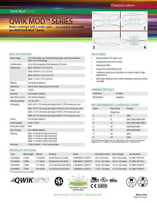
FEATURES• Diamondback 170º Optic Lens• I ntegrated aluminum heatsink• Waterproof IP68• Snap & Peel Qwik Release Tab• 4 different mod styles to perform in a wide variety of sign applications• More light diffusion with a wider batwing resulting in better coverageSPECIFICATIONSBeam Angle 170˚ Ultra-Wide Low Dome Batwing Optic with DiamondbackOptic Lens TechnologyCertifications UL & cUL Recognized (SAM Manual), CE, RoHsDimensions QM1: 0.69”W x 1.4”L x 0.25”HQM2: 0.69”W x 2.2”L x 0.25”HQM3: 0.69”W x 3.14”L x 0.25”HQM4: 1.7”W x 1.77”L x 0.25”HEfficacy See Product OptionsFastening Peel & Stick / Mechanical Screw HoleInput12VDCIntensity See Product OptionsMax Mods (Series)See Product OptionsOperating Temp-30º to +60ºCPackaging QM1: 60 ft. (150 mods) per bag or 600 ft. (1500 mods) per caseQM2: 44.7 ft. (76 mods) per bag or 536.52 ft. (912 mods) per caseQM3: 33.3 ft. (50 mods) per bag or 500 ft. (750 mods) per caseQM4: 25.3 ft. (38 mods) per bag or 608 ft. (912 mods) per casePower See Product OptionsPower Supply P-LED 12VDCProtection Grade IP68Run Footage See Product OptionsSpacing QM1: 2.5 mods/ft. (fully stretched)QM2: 1.7 mods/ft. (fully stretched)QM3: 1.5 mods/ft. (fully stretched)QM4: 1.5 mods/ft. (fully stretched)Warranty 5 Year Product / 5 Year Limited LaborPRODUCT OPTIONSColor Wavelength Efficacy Intensity Power Max Mods (Series)Run Footage Part Number*True White7100K110 LM/W44 LM/mod (110 LM/ft)0.4W/MOD (1.0W/FT)30 ft. (75 mods)60 ft. (150 mods)PL-QM1-TW110-P True White7100K111 LM/W89 LM/mod (150 LM/ft)0.8W/MOD (1.36W/FT)22.3 ft. (38 mods)44.7 ft. (76 mods)PL-QM2-TW150-P True White7100K111 LM/W133.5 LM/mod (200 LM/ft) 1.2W/MOD (1.8W/FT)16.6 ft. (25 mods)33.3 ft. (50 mods)PL-QM3-TW200-P True White7100K109 LM/W174 LM/mod (260 LM/ft) 1.6W/MOD (2.4W/FT)12.6 ft. (19 mods)25.3 ft.(38 mods)PL-QM4-TW260-P•325-227-4577•***************REV20170405WIRING DETAILSWhite/Red PostitiveWhite/Black Negative1234RECOMMENDED COVERAGE CHARTDepth Max. Stroke ProductSingle Row2”6”QM13”8”QM1/QM2/QM3/QM44”12”QM1/QM2/QM3/QM45”16”QM2/QM3/QM46”18”QM2/QM3/QM47”22”QM38”24”QM4Note: Product and depth may vary depending on face material and desiredbrightness. For 2” depths increase module density to 3 mods per foot.Wwarranty5P 5L* “P” denotes lens factory installed.Subject to changes.。
ENMade in Germany1 Included in delivery 32 Adapters 43 Product Description4 Technical specifications 4 Contact information5 Warranty54 Buttons and Displays 6 4.1 Buttons 6 4.2 Boost-Buttons LEDs 7 4.3 LCD 7 Network behavior 8 4.4 Inclusion 9 4.5 Mounting the Spirit Z-Wave Plus 10 4.6 Plus Mechanical Installation 11 4.7 Exclusion 12 4.8 Unmounting the Spirit Z-Wave 13 4.9 Plus Factory Rese 13 5 Operating the device 14 5.1 Setpoint adjustment 14 5.2Child protection14Content5.3 Altering the operating states 14 5.4 Window open detection 15 5.5 Display NodeID 156 Z-Wave 166.1 Assoziation 17 6.2 Basic17 6.3 Configuration 18 6.4 Multilevel Sensor 18 6.5 Multilevel Switch 19 6.6 Notification 19 6.7 Protection 19 6.8 Thermostat Mode 19 6.9 Thermostat Setpoint 207 T roubleshooting201. Spirit Z-Wave Plus energy-saving thermostat2. Screw3. Adapters for Danfoss valves4. 2x AA batteries1. Included in deliveryRASpirit Z-Wave Plusenergy-saving thermostat2x AA batteries Screw for adapter* When using the RAV adapter, you need the RAV Pinfor the extension of the valve stem.WARNING - Remove the connecting pieces of the plastic adapter completely before you use one of the supplied adapters!Additional adapters are available for different valve manufacturers. Please consult the EUROtronic Website for all information about the different adapters at: /Service/FAQFor the following valves no adapter is required:Heimeier, Junkers Landy + Gyr, MNG, Honeywell, Braukmann, as these have a thread of M30 x 1.5mm. The adapters for Danfoss RAV (pin must be plugged on the valve tappet) Danfoss RA and Danfoss RAVL are included.For the following valves an adapter is required:Herz M28 x 1,5 mm, Comap M28 x 1,5 mm, Vaillant 30,5 mm, Oventrop M30 x 1,0 mm, Meges M38 x 1,5 mm, Ondal M38 x 1,5 mm, Giacomini 22,6 mm, Rossweiner M33 x 2,0 mm, Markaryd M28 x 1,0 mm,, Ista M32 x 1,0 mm, Vama M28 x 1,0 mm, Pettinaroli M28 x 1,5 mm, T+A M28 x 1,5 mm, Gampper 1/2/6.If you are not sure which valve you are using, please visit: /Produkte/Adapter for fur-ther Information. Here you will find a list of various valves and adapters.2. AdaptersSpirit Z-Wave Plus is a Z-Wave radio standard compatible energy-saving radiator thermostat. FLiRS (Frequently Listening Receiver Slave):Spirit Z-Wave uses FLiRS to provide short latency and short responding times.3. Product DescriptionIf you wish to receive further technical Support or information about other EUROtronic products, please contact us via E-Mail or telephone.Customer Service:Eurotronic Technology GmbH Südweg 136396 Steinau-Ulmbach GermanyContact informationTelefon: 0 66 67 / 9 18 47-0Servicehotline: 0 66 67 / 9 18 47-17 eMail:*******************Internet: WarrantyThe 24-months warranty period begins at the day of purchase. Please keep the receipt as evidence of pur-chase. During the warranty period, defective radiator thermostats may be sent to your dealer or the address below. Please ensure sufficient postage is paid. A new or repaired device will then be sent to you free of charge.Please note that EUROtronic only grants warranty on the function of the device. EUROtronic will not grant war-ranty for the interaction between the thermostat and the bottom part of the valve. The technical data is only valid for the use of the following valves: Heimeier, Junkers Landys + Gyr, MNG, Honeywell, Braukmann (mea-sure of thread M30 x 1,5), Oventrop (M30 x 1,5) Danfoss RA, RAV and RAVL. Please refer to the combinations of the devices on our website (https:///produkte/adapter-information.html) EUROtronic does not issue a guarantee when using the thermostat with valves which are not mentioned above.Declaration of Conformity:Eurotronic Technology GmbH hereby declares that this device is compliant with the essential require-ments and other relevant provisions. The declaration of conformity is provided at . Advice on environmental protection:From the date of implementation of European guidelines 2002/96/EC and 2006/66/EC, into national law, the following applies: Electric and electronic devices and batteries may not be disposed of in household waste. The consumer is obliged to return electric and electronic devices and batteries to the public col-lection points established for them or to the point of sale. The particulars of this are regulated by the applicable state laws. The symbol on the product, operation instructions or packaging points to these provisions. You make an important contribution to the protection of the environment by reusing or recycling old equipment/bat-teries or making use of them in other ways.WarningDo not use rechargeable batteries!Never recharge batteries, do not short circuit them, do not take them apart - Risk of explosion! Remove dead batteries from the device immediately. Do not use old and new batteries together. Clean battery and device contacts before inserting if necessary.Keep batteries away from children. Avoid contact with skin, eyes and mucous membranes. In case ofcontact with battery acid, rinse the affected areas immediately with plenty of water, and seek medical atten-tion immediately. Do not expose batteries to direct sunlight.Safety Instructions: Spirit Z-Wave Plus is designed for use in buildings. Operate Spirit Z-Wave Plus only as described in the user manual. Spirit Z-Wave Plus should only be put to use in a dry and dust-free place, away from direct sunlight. Do not keep using the device when there is obvious damage. Spirit Z-Wave Plus may not be rebuilt, modified or opened.4.1 Buttons4. Buttons and Display&Minus PlusBoostTechnical specificationsDevice short description Spirit Z-Wave Plus EAN4260012711301Article Number 701003Supply Voltage 2 x 1,5V LR6/Mignon/AA Radio Frequency 868,42 MHz ConnectionM30 x 1,5mmMethod of operation Type 1Dimensions (W x H x D): 56 x 68 x 89 mm Weight176g (incl. batteries)Degree of protection IP20Degree of pollution24.3 LCDColorState MeaningBlinkingOver the Air update of the actuator software in progress. Temperature regulation is not possible during this process. Lights constantly A task has failed.Boost – green Boost – redWrench:Lights up if mechanical tasks are ongoing.Antenna:Displays the Spirit Z-Wave Plus network state. Segment visible: rf-link established Segment turned off: rf-link lostID: Lights up if the Display shows the Z-Wave NodeID.Battery: Lights up if less than 15% battery is remaining Lock: Lights up if child protection is set.Celsius: Displayed if the LCD shows a setpoint temperaturePercent: Displayed instead of °C Icon if the Comet Z Plus is set to direct. control mode.On factory default the device does not belong to any Z-Wave network Spirit Z-Wave Plus needs to be added to an existing wireless network to communicate with the devices of this network. This process is called Inclusion.Spirit Z-Wave Plus can also be removed from a network. This process is called Exclusion. Both processes are initiated by the primary controller of the Z-Wave network. This control-ler is turned into exclusion respective inclusion mode. Please consult the manual of your Z-Wave Controller how to activate Inclusion or Exclusion mode.If Spirit Z-Wave Plus has been added to anetwork, it has to be removed prior to be added to another wireless network.Network behaviorInteroperabilityThis device and every other certified Z-Wave device can be used together with any other certified Z-Wave device regardless of brand and origin as long as both are suited for the same frequency range.SecuritySpirit Z-Wave Plus supports secure communi-cation. Spirit Z-Wave Plus will communicate with other devices secure as long as this device provides the same or a higher level of security. Otherwise Spirit Z-Wave Plus will automatically turn into a lower level of security.Inserting batteriesRemove the battery cover by simply pulling it off. Now insert the batteries. Pay attention to the correctpolarity! At a later battery change, the configuration of your Spirit Z-Wave Plus is maintained.4.4 InclusionStart Inclusion mode of your primary Z-Wave Controller. Press the Boost-Button.Spirit Z-Wave Plus will show the assigned NodeID.After adding the Spirit Z-Wave Plus to a network it is ready to be installed on the radiator. The LCD shows INS. Do not press the boost button yet.4.5 Mounting the Spirit Z-Wave Plus4.6 Mechanical InstallationPress the boost button to start mechanical installation.4.7 ExclusionStart Exclusion mode of your primary Z-Wave Controller.Now press and hold the boost button of the Spirit Z-Wave Plus for at least 5 seconds.Remove the Spirit Z-Wave Plus from the Z-Wave network before unmounting it. Follow the process described in Exclusion and wait until the LCD shows INC. You can now uninstall Spirit Z-Wave Plus from the radiator.Remove batteries.Press and hold boost button.While still holding boost button insert batteries. The LCD shows RES. Release boost button. To perform the factory reset press boost button.2.1.Please use this procedure only when the network primary controller is missing or otherwise inoperable.DEFRES Press Boost button to perform reset.Defaults restoredNode XXX removed4.8 Unmounting the Spirit Z-Wave Plus4.9 Factory Reset5 Operating the deviceThe LCD shows the configured set point or the valve opening percentage if the device is in manufacturer specific mode.5.1 Setpoint adjustmentThe setpoint is adjusted via plus and minus button.Altering the setpoint locally will set the Spirit Z-Wave Plus in heating mode.The energy saving setpoint can only be adjusted via Z-Wave.The configurable setpoint range is 8°C to 28°C.If the setpoint is increased/decreased above/below the set point limits theSpirit Z-Wave Plus will change into boost / off –mode.5.2 Child protectionPress and hold plus and minus button simultaneously for 3 secondsto enable/disable the child protection.If the Spirit Z-Wave Plus is set into the highest protection level it is nolonger possible to operate the device locally.5.3 Altering the operating statesOff-ModePress minus button until OFF is displayed.Boost-ModePush the boost button.Alternatively press the plus button until ON is displayed.Heating-ModeIf the operating state is not heating mode, pressing the plus orminus button will bring the device in heating mode.5.4 Window open detectionIf the roomtemperature drops the window open detection will trigger.Spirit Z-Wave Plus will change temporarily in off mode for 15 minutes.Window open detection will end automatically after 15 minutes and the previously active operating mode will be restored.Window open detection can also be canceled by a button press.The window open detection is disabled during manufacturer specific mode.The sensitivity oft he window open detection can be configured5.5 Display NodeIDPress and hold the boost button for 3 seconds to display the NodeID.6 Z-WaveCommand Class Description Version Control (C)Security *Support (S) Association Allows to associate with other Z-Wave devices.2S U, S0, S2 Allows to group associations. 1S U, S0, S2 Association GroupInformationBasic Provides access to basic functionality.1S U, S0, S2 Battery Returns the current battery level of the device.1S U, S0, S2 Configuration Allows to configure the device settings.1S U, S0, S2 Device Reset Locally Informs the Z-Wave Controller that the device was factory reset. 1S U, S0, S2 Firmware UpdateAllows Over the Air Update of the device.3S U, S0, S2 Meta DataManufacturer Specific Provides information about Manufacturer and Product.1S U, S0, S2 Multilevel Sensor Provides the measured room temperature.5S U, S0, S2 Multilevel Switch Provides or sets the valve opening degree of the valve Controlling1S U, S0, S2 the valve opening degree requires manufacturer specific mode.Notification Informs the controller about critical system events/errors.8S U, S0, S2 Power Level Used to alter the rf-power(required by Z-Wave). 1S U, S0, S2 Protection Allows to lock the device(child protection).1S U, S0, S2 Security Allows encrypted Z-Wave Communication.2S U Thermostat Mode Configures the operation mode. 3S U, S0, S2 Thermostat Setpoint Allows to configure the desired room temperature. 3S U, S0, S2 Transport Service Handles the transmission of large telegrams.2S U Version Returns information about the Firmware.2S U, S0, S2 Z-Wave Plus Info Identifies the device as a Z-Wave Plus Device.1S U*Availability of the Command Class after adding the Spirit Z-Wave Plus to your Z-Wave network.U UnsecureS0 Z-Wave Security standard S0S2 Z-Wave Security standard S26.2 BasicSpirit Z-Wave Plus can only be associated with the Z-Wave controller.Control basic functions of the Spirit Z-Wave Plus via basic command class.Group No Description CommandsMax supported Nodes1LifelineBATTERY_REPORT,DEVICE_RESET_LOCALLY_NOTIFICATION,THERMOSTAT_MODE_REPORT,THERMOSTAT_SETPOINT_REPORT,NOTIFICATION_REPORT,PROTECTION_REPORT,SENSOR_MULTILEVEL_REPORT,SWITCH_MULTILEVEL_REPORT1Value Description Function0x00Energy Save Heating Switches into energy save heating mode. The room temperature will be lowered to the configured setpoint in order to save. energy. 0x0F OFF No Heating. Only Frost-protection.0xF0Full Power HeatingSwitches into Boost mode(Quick heat).0xFE Manufacturer Specific Switches into direct Valve control mode. 0xFFHeatingSwitches into comfort heating mode.The room temperature will be kept at the configured comfortable level.6.4 Multilevel SensorSpirit Z-Wave Plus can be configured during runtime.Spirit Z-Wave Plus measured the room temperature and automatically reports sensor readings to associated devices. Per default the reporting threshold is ±0.5°C. This parameter can be altered via configuration command class.Parameter number Size in Byte Name Description11LCD Invert0x00 LCD-content normal0x01 LCD-content inverted (UK Edition)default: 0x0021LCD Timeout0x00 No Timeout LCD always on0x05-0x1E LCD will turn off after 5 to 30 seconds. default: 0x0031Backlight0x00 Backlight disabled 0x01 Backlight enabled default: 0x0141Battery report0x00 Battery status is only reported as a system notification (Notification CC) 0x01 Send battery status unsolicited once a day. default: 0x0151Measured Temperature report 0x00 Unsolicited Temperature reporting disabled.0x01 – 0x32 report if temperature changed by delta = 0,1°C … 5,0 °Cdefault 0x05 (report on delta T = 0,5°C)61Valve opening percentage report 0x00 Unsolicited valve opening percentage reporting disabled. 0x01-0x64 report if valve opening changed by delta = 1% … 100% default 0x0071Window open detection0x00 Disabled0x01 Sensitivity low 0x02 Sensitivity medium 0x03 Sensitivity high default: 0x02 medium81Measured Temperature offset 0xCE-0x32 Offsets the measured temperature by-5,0°C – (+)5,0°C 0x80 External temperature sensor will be used for regulation.default: 0x00 0,0°C OffsetThe measured room temperature can be adjusted with an offset. Spirit Z-Wave Plus can receive temperature readings from other Z-Wave devices (wall thermostat for example) The external tempera-ture can be used for temperature regulation. This feature has to be enabled via configuration parameter. The Spirit Z-Wave Plus can handle Multilevel Sensor Reports in the following format:Report outgoing:Sensor type: …Air Temperature“Scale: Celsius Precision:2Report incoming:Sensor type: …Air Temperature“Scale: Celsius and Fahrenheit Precision:0, 1 and 26.5 Multilevel Switch6.6 NotificationAllows to request the valve opening in percent. 0% represents a fully shut valve. 100 % a fully open valve. The valve opening can be reported on change. If the configuration parameter is set. Spirit Z-Wave Plus will send notifications on certain events.Notification type ReasonDescriptionPowerManagement Replace battery soonNotification is sent if less than 25% battery remainingPowerManagement Replace battery now Notification is sent if less than 15% battery remainingSystemSystem Hardware failure with manufacturer proprietary failure code Provides manufacturer specific error codes for mechanical problems 0x01 Motor movement not possible 0x02 Not mounted on a valve0x03 Valve closing point could not be detected 0x04 Piston positioning failed6.7 ProtectionSpirit Z-Wave Plus can be locked remotely.Protection level Description0x00Unprotected regular operation possible0x01Restricted: device can be unlocked using a button pattern.0x02No local operation possible.6.8Thermostat ModeSpirit Z-Wave Plus offers the following modes.Mode Name Description0x00Off No heating. Only frost protection.0x01Heat Switches into comfort heating mode. The room temperature will be kept at the configured comfortable level.0x0B Energy Heat Switches into energy save heating mode. The room temperature will be lowe-red to the configured setpoint in order to save energy.0x0FFull PowerSwitches into Boost mode (Quick heat). Spirit Z-Wave Plus heats the room up as fast as possible. The mode is left automatically after 5 minutes or earlier if requested by the user(via Z-Wave or locally on the device).0x1F Manufacturer SpecificSwitches into direct valve control mode. The valve opening percentage can be controlled using the Switch multilevel command class.6.9 Thermostat SetpointThe following setpoints of the Spirit Z-Wave Plus can be altered.Modus Name Precision Scale Temp. Range 0x01Heat0,1 and 2Celsius and Fahrenheit8°C-28°C0x0B Energy Heat0,1 and 2Celsius and Fahrenheit8°C-28°C 7 T roubleshootingProblem Reason SolutionBatterie Icon Batteries do not haveenough power.Replace batteries.Heating element does not warm up.Is the boiler water temperature O.K.?Valve does not open, is it calcifiedafter the summer pause/heatingpause.Adjust the temperature of the boiler water.Remove the Comet Blue, move the valve back and forthper hand or with a tool.Heating element does not cool down.Valve does not close completely.It may be that the closing pointof your valve seat has shifted.Unmount Spirit Z-Wave Plus. Move the valve stem severaltimes by hand, it may be that adaptation is impossiblebecause your valve is calcified or the seat no longerperforms its function.Pressure piece falls out (This can also cause an E1-error)Due to an endless thread thepressure piece, which is situatedat the bottom, can fall out if thedevice has not been affixed on thevalve.Remove batteries. Put in the pressure piece.Insert the batteries. The endless thread is rotatingnow and fixes the pressure piece again.ER1-3 and ERR The error code can be cleared bypressing the boost button.Err Inclusion failed Z-Wave Controller out of range.ER1Valve positioning not possible Check if the valve is jammed.ER2Valve not detected Check if the Spirit Z-Wave Plus is correctly mounted. ER3Valves closing point not detected Check if the Spirit Z-Wave Plus is correctly mounted.。
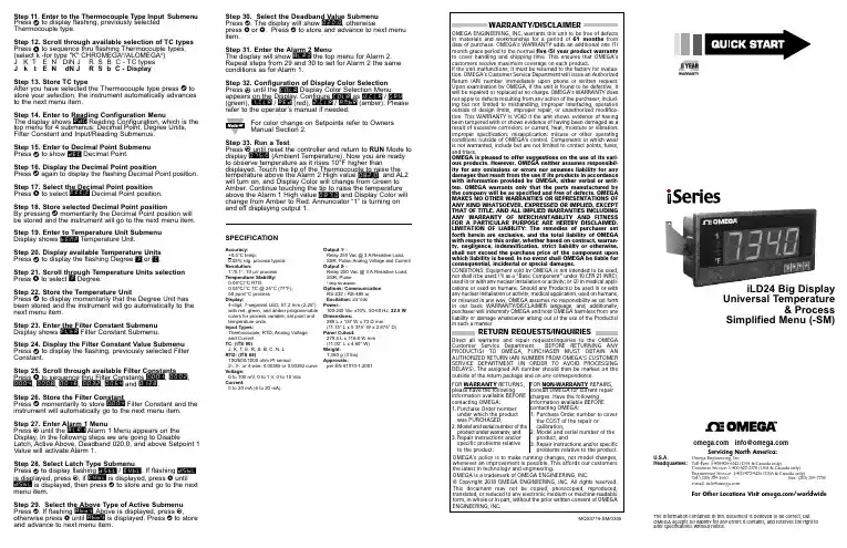
Step 11. Enter to the Thermocouple Type Input Submenu Press d to display flashing, previously selected Thermocouple type.Step 12. Scroll through available selection of TC types Press b to sequence thru flashing Thermocouple types,(select k -for type "K" CHROMEGA ®/ALOMEGA ®)J K T E N DIN J R S B C - TC types J k t E N dN J R S b C - DisplayStep 13. Store TC typeAfter you have selected the Thermocouple type press d to store your selection, the instrument automatically advances to the next menu item.Step 14. Enter to Reading Configuration MenuThe display shows RDG Reading Configuration, which is the top menu for 4 submenus: Decimal Point, Degree Units,Filter Constant and Input/Reading Submenus.Step 15. Enter to Decimal Point Submenu Press d to show DEC Decimal Point.Step 16. Display the Decimal Point positionPress d again to display the flashing Decimal Point position.Step 17. Select the Decimal Point position Press b to select FFF.F Decimal Point position.Step 18. Store selected Decimal Point positionBy pressing d momentarily the Decimal Point position will be stored and the instrument will go to the next menu item.Step 19. Enter to Temperature Unit Submenu Display shows TEMP Temperature Unit.Step 20. Display available Temperature Units Press d to display the flashing Degree °F or °C .Step 21. Scroll through Temperature Units selection Press b to select °F Degree.Step 22. Store the Temperature UnitPress d to display momentarily that the Degree Unit has been stored and the instrument will go automatically to the next menu item.Step 23. Enter the Filter Constant Submenu Display shows FLTR Filter Constant Submenu.Step 24. Display the Filter Constant Value Submenu Press d to display the flashing, previously selected Filter Constant.Step 25. Scroll through available Filter Constants Press b to sequence thru Filter Constants 0001, 0002,0004, 0008, 0016, 0032, 0064and 0128.Step 26. Store the Filter ConstantPress d momentarily to store 0004Filter Constant and the instrument will automatically go to the next menu item.Step 27. Enter Alarm 1 MenuPress a until the ALR1Alarm 1 Menu appears on the Display. In the following steps we are going to DisableLatch, Active Above, Deadband 020.0, and above Setpoint 1Value will activate Alarm 1.Step 28. Select Latch Type SubmenuPress d to display flashing DSBL / ENBL .If flashing DSBL is displayed, press a , if ENBL is displayed, press buntil DSBL is displayed, then press d to store and go to the next menu item.Step 29. Select the Above Type of Active Submenu Press d . If flashing ABoV Above is displayed, press a ,otherwise press b until ABoV is displayed. Press d to store and advance to next menu item.MQS3716-SM/0305iLD24 Big Display Universal Temperature&ProcessSimplified Menu (-SM)WARRANTY/DISCLAIMEROMEGA ENGINEERING, INC. warrants this unit to be free of defects in materials and workmanship for a period of 61 months from date of purchase. OMEGA’s WARRANTY adds an additional one (1) month grace period to the normal five (5) year product warranty to cover handling and shipping time. T his ensures that OMEGA’s customers receive maximum coverage on each product.If the unit malfunctions, it must be returned to the factory for evalua-tion. OMEGA’s Customer Service Department will issue an Authorized Return (AR) number immediately upon phone or written request. Upon examination by OMEGA, if the unit is found to be defective, it will be repaired or replaced at no charge. OMEGA’s WARRANTY does not apply to defects resulting from any action of the purchaser, includ-ing but not limited to mishandling, improper interfacing, operation outside of design limits, improper repair, or unauthorized modifica-tion. This WARRANTY is VOID if the unit shows evidence of having been tampered with or shows evidence of having been damaged as a result of excessive corrosion; or current, heat, moisture or vibration; improper specification; misapplication; misuse or other operating conditions outside of OMEGA’s control. Components in which wear is not warranted, include but are not limited to contact points, fuses, and triacs.OMEGA is pleased to offer suggestions on the use of its vari-ous products. However, OMEGA neither assumes responsibil-ity for any omissions or errors nor assumes liability for any damages that result from the use if its products in accordance with information provided by OMEGA, either verbal or writ-ten. OMEGA warrants only that the parts manufactured by the company will be as specified and free of defects. OMEGA MAKES NO OTHER WARRANTIES OR REPRESENTATIONS OF ANY KIND WHATSOEVER, EXPRESSED OR IMPLIED, EXCEPT THAT OF TITLE, AND ALL IMPLIED WARRANTIES INCLUDING ANY W ARRANTY OF MERCHANTABILITY AND FITNESS FOR A PARTICULAR PURPOSE ARE HEREBY DISCLAIMED. LIMITATION OF LIABILITY: The remedies of purchaser set forth herein are exclusive, and the total liability of OMEGA with respect to this order, whether based on contract, warran-ty, negligence, indemnification, strict liability or otherwise, shall not exceed the purchase price of the component upon which liability is based. In no event shall OMEGA be liable for consequential, incidental or special damages.CONDITIONS: Equipment sold by OMEGA is not intended to be used, nor shall it be used: (1) as a “Basic Component” under 10 CFR 21 (NRC), used in or with any nuclear installation or activity; or (2) in medical appli-cations or used on humans. Should any Product(s) be used in or with any nuclear installation or activity, medical application, used on humans, or misused in any way, OMEGA assumes no responsibility as set forth in our basic WARRANT Y/DISCLAIMER language, and, additionally, purchaser will indemnify OMEGA and hold OMEGA harmless from any liability or damage whatsoever arising out of the use of the Product(s) in such a manner.RETURN REQUESTS/INQUIRIESDirect all warranty and repair requests/inquiries to the OMEGA Customer Service Department. BEFORE RE URNING ANY PRODUC (S) O OMEGA, PURCHASER MUS OB AIN AN AUTHORIZED RETURN (AR) NUMBER FROM OMEGA’S CUSTOMER SERVICE DEPART MENT (IN ORDER T O AVOID PROCESSING DELAYS). T he assigned AR number should then be marked on the outside of the return package and on any correspondence.FOR WARRANTY RETURNS, please have the followinginformation available BEFORE contacting OMEGA:1. Purchase Order number under which the product was PURCHASED,2.3. Model and serial number of the product under warranty, and Repair instructions and/or specific problems relative to the product.FOR NON-WARRANTY REPAIRS, consult OMEGA for current repair charges. Have the following information available BEFORE contacting OMEGA:1. P urchase Order number to cover the COST of the repair or calibration,2.3.Model and serial number of the product, and R epair instructions and/or specific problems relative to the product.OMEGA’s policy is to make running changes, not model changes, whenever an improvement is possible. This affords our customers the latest in technology and engineering.OMEGA is a trademark of OMEGA ENGINEERING, INC.© Copyright 2018 OMEGA ENGINEERING, INC. All rights reserved. T his document may not be copied, photocopied, reproduced, translated, or reduced to any electronic medium or machine-readable form, in whole or in part, without the prior written consent of OMEGA ENGINEERING, INC.***********************Servicing North America:Omega Engineering, Inc.Toll-Free: 1-800-826-6342 (USA & Canada only)Customer Service: 1-800-622-2378 (USA & Canada only) Engineering Service: 1-800-872-9436 (USA & Canada only) Tel: (203) 359-1660 Fax: (203) 359-7700 e-mail:**************For Other Locations Visit /worldwidehis Quick Start Reference provides information on setting up your instrument for basic operation. The latest complete Communication and Operational Manual as well as free Software and ActiveX Controls are available at or on the CD-ROM enclosed with your shipment .SAFETY CONSIDERATIONThe instrument is a panel mount device protected in accordance with EN 61010-1:2001, electrical safetyrequirements for electrical equipment for measurement, control and laboratory.Remember that the unit has no power-on switch. Building installation should include a switch or circuit-breaker that must be compliant to IEC 947-1 and 947-3.SAFETY:•Do not exceed voltage rating on the label located on the back of the instrument housing.•Always disconnect power before changing signal and power connections.•Do not use this instrument on a work bench without its case for safety reasons.•Do not operate this instrument in flammable or explosive atmospheres.EMC:•Whenever EMC is an issue, always use shielded cables. •Never run signal and power wires in the same conduit.•Use signal wire connections with twisted-pair cables.•Install Ferrite Bead(s) on signal wire close to the instrument if EMC problems persist.。
恒温加热台使用方法(一)恒温加热台使用方法详解什么是恒温加热台?恒温加热台是一种专门用于实验室或工业生产中的设备,能够提供恒定的温度环境来加热样品或反应容器。
它具有温度稳定、控制精度高等特点,广泛应用于化学、生物、医药等领域。
恒温加热台的使用方法步骤1:准备工作1.确保恒温加热台的电源线已经连接到稳定可靠的电源插座,电源开关处于关闭状态。
2.检查恒温加热台的加热盘和控制面板是否清洁,并做好相应的清洁工作。
步骤2:设置温度1.打开恒温加热台的电源开关,待显示屏上出现相关信息后,进入温度设置界面。
2.通过控制面板上的温度调节按钮,调整加热台的温度设定值。
通常可通过“上”和“下”按钮进行微调。
3.确定设定值后,按下确认键,开始加热。
步骤3:放置样品1.将需要加热的样品或反应容器放置在恒温加热台的加热盘上。
确保样品平稳并与加热盘接触良好。
2.注意避免样品或容器与恒温加热台的控制面板、电源线等接触,以防影响加热效果或造成安全隐患。
步骤4:加热过程1.恒温加热台开始加热后,会以设定温度作为目标,尽可能保持加热盘上的温度稳定。
2.在加热过程中,可以通过恒温加热台的显示屏上的温度显示,实时监测加热盘上的温度变化。
步骤5:加热结果1.当样品达到所需的温度后,可根据实验需求进行相应的操作。
2.加热结束后,关闭恒温加热台的电源开关,待设备冷却后再进行清洁和存放。
常见问题及解决方法问题1:恒温加热台无法正常加热解决方法:检查电源线是否连接良好,确保电源供应稳定,若问题仍未解决,建议联系售后服务。
问题2:加热盘温度不稳定解决方法:检查加热盘是否有杂物或污垢影响散热,清洁加热盘后再试,若问题仍未解决,建议联系售后服务。
问题3:温度显示与实际温度不一致解决方法:进行温度校准,按照设备说明书中的方法进行校准,若问题仍未解决,建议联系售后服务。
小结恒温加热台是一种功能强大的加热设备,在实验和生产中起到重要作用。
正确使用恒温加热台并掌握常见问题的解决方法,能够提高工作效率和实验数据的可靠性。

User Manual 1TZT-100 Multi-functionThermostatPlease take time to read and understand these instructions. Doing so will assist you to benefit from the many features offered in this premium product.If properly installed, your thermostat will provide years of trouble- free control of the air temperature within your living or working environment.The TZT-100 thermostat has been designed and built by Smart Temp Australia P/L, to be an attractive, highly reliable and an easy to use thermostat. The TZT-100 model is a modified version of a standard Smart Temp product. It has been configured specifically to Oasis Heat Pumps requirements for use on Oasis Heat and Chill Heat PumpsCare has been taken in the preparation of this manual. However, Oasis takes no responsibility for errors or omissions in this document. It is the responsibility of the user to ensure this thermostat and the equipment connected to it, is operating to theirspecifications, and in a safe manner.Due to ongoing product improvement Smart Temp Pty. Ltd., Oasis. reserve the right to change the specifications of this thermostat (or its components) without notice. . Any such changes may impact upon the operational detail described in this manual. The user should ensure they are reading documentation which relates to the version of thermostat they have..Table of ContentsIntroductionCommercial Programmable modeOn / Off and Mode SelectionSetting the ClockProgramming Your 2 Daily Events9After Hours Rn TimerManual modelOn / Off and Mode SelectionSetting the Fan FunctionSetting the ClockSetting Your Desired TemperatureSwitching Between Day and Night Set PointsTo Review the Set TemperatureCommon FunctionsThe Buttons Explained – ON/Off and Mode Selection etc Control ModesFan FunctionsThis TZT-100 thermostat is able to be used as a residential programmable thermostat, a commercial programmable thermostat or as a simple to use manual thermostat. Your installer will have set these modes to best suit your individual needs.For clarity, this user manual is broken into the following main sections.Commercial Programmable Mode.Allows programming of 1 “Start” and 1 “Stop” time and temperature per day.Manual Mode. (See page 18 of this manual).Use the MODE button to switch On and Off. No time-related programming available.Common Functions - All modes..Commercial Programmable ModeOn /Off and Mode SelectionTap the “MODE” button to cycle the thermostat throughthe available modes: “Heat” only, “Cool” only, Auto-changeover (Shown by both “Heat” & “Cool” in the LCD),Emergency Heat (if fitted), and “OFF”. If the fan mode isset to “Fan On”, when you select “OFF” mode the f anmode will automatically change to “Auto Fan” to preventthe fan from running unexpectedly while the unit is OFF.(Note – Not all modes may be active on your thermostat). Setting the ClockThe thermostat is fitted with a real time clock. This clock is used by the thermostat for the programming functions as described below.It is essential that the clock time and day are set accurately if you require your programmed events to start on time.To set the clock, tap the “PROG”button. The LCD will show the hours digit flashing. Use the up ()or down ()button to adjust the hours to the correct time(note the AM / PM symbol). Tap the “PROG”button again and now the minutes digits will flash.Adjust this value using the up ()or down ()button to show the correct minute. Tap the “PROG”button again and now the weekday flashes, again use the up ()or down () button to set this value to the correct day of the week. Tap the “PROG”button again to exit the clock set function.Programming Your 2 Daily EventsCommercial programming of the thermostat has been designed to be an extremely simple and logical process. The thermostat permits you to program a START time for the air conditioning system, then a Stop time for each day of the week. When the thermostat i s displaying “START” in the LCD, it will maintain whatever set point has been chosen. When the thermostat is displaying “STOP”in the LCD it will be OFF (or it will maintain an energyefficient overnight temperature if set by the installer).To enter the program mode:Press and hold the “PROG” button for 3 seconds. Thedisplay will change to show the Day “Monday” flashing.Using the up()or down()buttons adjust the dayto the day you wish to start programming an event or tothe day you wish to edit an existing event.Tap the “PROG” button to advance to the next step, TheLCD will show the word “START” with the hour’s digiting the up ()or down ()buttons adjustthe hours value to the time you wish the building AirConditioning system to start.Tap the “PROG” button again, now the minute’s digitsing the up ()or down ()b u t t o n s set theminute to the time you wish the building air conditioningsystem t o “START” for the currently selected day.Tap the “PROG” button to advance to the next step, The LCD will show the word “STOP”with the hour’s digit ing the up ()or down ()buttons adjust thehours to the time you wish the building air conditioningsystem to “STOP” for the currently selected day.Tap the “PROG”button again, now the minute’s digitsing the up ()or down ()b u t t o n s set theminute to the time you wish the building airconditioning system to “STOP” for the currentlyselected day. The LCD will now show the word “COPY”.You now have TWO optionsOption 1 - Continue programming as above.Simply continue to tap the “PROG” Button as you have been previously to advance to thenext day, “Tuesday” in this example “START” then “STOP” times, then Wednesday, Thursday etc, following the same simple steps previously explained….OROption 2 –“Copy” ProgramTo copy the values you have just set to other days of theweek tap the up()or down()buttons to“T A G”eachadditional day you wish to copy the currently set daysprogram to. When you have finished “Tagging” the daysyou desire press the “PROG”button to initiate the copyprocess. The word “Copy” will flash briefly to confirm thecopy process and your current days values will be copiedto the days selected. Normal programming will resume atthe next day to be programmed.Please Note –Your thermostat’s programs may be controlled from a Building Management System (BMS) thereby overriding any program you may have entered, as described ab ove. If the BMS is controlling the thermostat the word “Start” or“Stop” will flash in the LCD to indicate the thermostat program is under BMS control.After Hours Run TimerFor convenience, the installer may have set the after-hours run function. This function permits you to temporarily turn the thermostat back on for an installer pre-set period of time if the “Stop” program is running, at the conclusion of which the thermostat will automatically turn back off again.To activate the after-hours run timer, simply tap the“O/RIDE” button. (Or, the optional “After Hours” runbutton on the remote room temperature sensor.) The LCDwill show the word “Override” flashing in the LCD.You can cancel any unexpired portion of the timer periodby tapping the “O/RIDE” button again. The word“Override” will vanish from the screen.To Review the Set Temperature:Simply tap the up ()or down ()button to first turn the LCD backlight t h e n again to display the currently set temperature.Your Installer may have set a default “Start” event temperature that will be used at the commencement of each day; this will override any previous day’s temperature adjustments.Manual ModeON / OFF and Mode SelectionTap the “MODE” button to cycle through all the availablemodes: “Heat”-only, “Cool”-only, Auto-changeover (Both“Heat” & “Cool” show in the LCD at the same time),Emergency Heat (if fitted), and “OFF”. If the fan mode isset to “Fan On”, when you select “OFF” mode, the fanmode will automatically change to “Auto Fan” to preventthe fan from running unexpectedly while the unit is OFF.(Note – Not all modes may be active on your thermostat). Setting the Fan FunctionDetail of the thermostat’s fan control functions can be found on page 26 of this manual. Setting the ClockThe thermostat has a real time clock. In Manual mode, this clock has no function other than to display the time. The clock display can be disabled by the installer if desired.To set the clock, press and hold the “PROG”button for 3 seconds. The LCD will show the hours digit(s)e the up()or down()button to adjust t h e hours to the correct time (note the AM / PM symbol). Tap the “PROG” button and now the minutes digits will flash.Adjust this value using the up()or down()button to show the correct minute.Tap the“PROG”button and now the week day e the up ()or down () button to set this value to the correct day of the week.Tap the“PROG”button again to exit the clock set function or simply wait 30 seconds to auto exit this screen and return to the main operating display.Your clock is now set.Setting Your Desired TemperaturePress and hold the up ()or down ()buttons for3seconds.The t h e r m o st at display will change to show the word “SET”, and the active set point for the current mode. (Heating or Cooling)as you hold the up ()or down ()buttons the current set point will change accordingly.If Auto mode is selected (Indicated by both “Heat” & “Cool” showing on the display at the same time); after adjusting the “Heat” set point, wait without touching a button for 3 seconds. The thermostat display will change to show “Cool”, “SET” and your curr ent cooling set temperature.If desired change this value with the up ()or down () buttons.Wait for another3seconds for the thermostat to automatically exit this temperature setting screen. Your new set temperatures will be maintained.Switching Between Day and Night Set PointsIf the function is set by your installer, the thermostat will keep two sets of temperatures in its memory. Typically one set is for daytime set point temperatures, and the other for the night settings.The thermostat provides a quick and simple way to change between your day and night time set temperatures. Simply tap the “PROG” button. The display will change, showing “Day” or “Night” in the top left hand corner as you switch between modes.Set the “Day” set temperature(s), separately from the “Night”. Each are set as described on the previous page.To Review the Set Temperature:Simply tap the up ()or down ()button to first turn the LCD backlight t h e n again to display the currently set temperature.Common FunctionsThe Buttons Explained – ON/Off and Mode Selection etcMODETap this button to cycle the thermostat through the available modes: “Heat” only, “Cool” only, Auto-changeover (Indicated by the wo rds; “Heat” and “Cool” being visible on the display at the same time), Emergency Heat (if fitted), and “OFF”. When setting the thermostat to “OFF” mode, the fan mode will automatically change to “Auto Fan” mode so the fan does not unexpectedly continue to run.(Note – Not all modes may be active on your thermostat.)O/RIDE (Override)Commercial Programmable Mode:This button initiates the after-hours run timer. When activated, the thermostat will temporarily replace the “Stop” program temperatures with the “Start” program temperatures for an installer-defined pre set period.Residential Programmable Mode:The “O/RIDE” button is used to override the current “event” time scheduling, and to hold the currently set temperature indefinitely. This set temperature will be maintained until released by tapping the “O/RIDE” button again. “Hold” will be displayed in the LCD to confirm this function is active.(Up)Use this button to increase the desired room temperature for “Heating” or “Cooling” modes, or to increase a “value” in programming modes. Also used to force an override of the pre-programmed temperatures and temporarily replace them with a new higher set temperature.(Down)Use this button to decrease the desired room temperature for “Heating” or “Cooling” modes, or to decrease a “value” in programming modes. Also used to force an override of the pre-programmed temperatures and temporarily replace them with a new lower set temperature.PROG (Program)In Residential or Commercial Programmable mode:Tap the “PROG” button to begin setting the clock. Press and hold the “PROG” button for 3 seconds to begin programming your daily e vents.In Manual mode:Tap the “PROG” button to switch between “Day” & “Night” modes. P ress and hold the “PROG” button for 3 seconds to begin setting the clock.Control Modes:Heat-only Mode - The thermostat will turn on the Heating when the room temperature falls below the Heat set point temperature. In Heat-only mode the thermostat will NOT bring on the Cooling regardless of the room temperature and the Cooling set point temperature. In Heat-only mode, only the word “Heat” will be displayed in the LCD. When your thermostat is calling for heat, the word “Heating” will b e displayed.If the word “Heat” is flashing, the thermostat is performing an Anti-Rapid-Cycle safety delay prior to restarting the heating cycle.E. Heat Mode - The thermostat will only use your emergency heating device to maintain your desired heating temperature. This method of heating can be quite expensive therefore Emergency Heat mode is not recommended unless it is essential. When your air conditioning system is heating using emergency heat, the word “E.Heat” in the LCD will change to the word “E.Heating”.Cool-only Mode - The thermostat will turn on the Cooling when the water temperature rises above the Cool set point. In Cool-only mode the thermostat will NOT bring on the Heating regardless of the water temperature and Heating set point temperature. In Cool-only mode, only the word “Cool” will be displayed in the LCD. When your heat pump system is cooling, the word “Cooling” will be displayed.If the word “Cool” is flashing, the thermostat is performing an Anti-Rapid-Cycle safety delay prior to restarting the Cooling.Auto-changeover Mode - The thermostat will turn on the Heating if the water temperature falls below the Heat Set point temperature. Likewise it will commence Cooling if the water temperature rises above the Cool Set point. This is the recommended mode as it provides automatic control of the heat pump system to maintain the desired water temperature. Auto-changeover mode is indicated by both words “Heat” & “Cool” showing in the LCD at the same time.If “Heat” or “Cool” is fl ashing; the thermostat is performing an Anti-Rapid-Cycle safety delay prior to restarting the air conditioning system.Padlock Symbol.Whenever this symbol is shown, a control limit has been reached, or a button,or other function has been locked out.Spanner Symbol.If you see a spanner ICON flashing on your LCD, the installer has left yourthermostat in “Commissioning mode” Although your thermostat will operateyour heating and cooling system whilst in “commissioning mode”, all activesafety and energy conservations delays have been disabled. It is thereforeHIGHLY recommended that you contact your installer and request that theinstaller mode be disabled.Satellite SymbolThis indicates that your thermostat is receiving or sending information toanother “communicating” controller, or a Building Management System.Information received from the building supervisory control system maychange the function (mode or set temperature) of the thermostat. This isnormal and no cause for concern.The intent of this communications is to permit the centralised control of building functions which can include building climate control. To achieve this the BMS must be able to override thermostat settings made by the user. This ability is especially useful when a large facility has a number of heat pumps.TEXT “Locked”:The temperature of the outside air can initiate, or prevent certain functions within the thermostat from operating. If this happens, the word “LOCKED” appears. These functions automatically “unlock” once the outside air temperature becomes favourable. TEXT “FAULT”The TZT-100 has been “requested” to shut down the heating, cooling or heat pump system as a response from an external command. This request may have come from a sensor fitted to the heat pump system, a sensor monitoring supply power or a multitude of safety interlocks that can be used. To clear this fault a service call to your service person may be necessary.Remote Temperature Sensors:Your thermostat is fitted with an accurate and reliable temperature sensor used to measure the water temperature. There may be occasions where the thermostat cannot be placed in an ideal location for water temperature measurement; therefore the installer may have fitted “remote temperature sensor(s)”. These sensors will then report the water temperature from the remote temperature location back to the thermostat where this temperature will be displayed on the LCD.If your thermostat is used in a commercial location, your water temperature sensor may be fitted with a button which activates the “After Hours” run function. Consult your installer if you require this feature or have questions about its use.Symptom Suspected Fault Suggested remedyTemperature display seems inaccurate Sensor location needs to be checked Make sure sensor is in correct position Position of sensor in titanium pocket Make sure sensor is at the bottom of thetitanium pocketSensor calibration may be incorrect Call your installer, Smart Temp or Oasis, forinformation on how tocalibrate the air temperature sensorA remote temperature sensor may be in use. The temperature is NOT being measured atthe thermostat location. The remotelocation may have a different temperature.“Locked” appears on LCD. Heating or Cooling will not operate. This is not a fault.Outside air temp too high to permit heatingOutside air temp too low to permit cooling.Heating and/or cooling disabled to conserveenergy. The heating or cooling function canbe disabled when the outsidetemperature is warm or cool enough to notwarrant the use of the heat pumpController has no display Check main fuse Reset Circuit breakerCall an approved service agent. Faulty Wiring Call an approved service agent.Heat Pump System seems to run all the time Heating and/or cooling temperatures set to anun-achievable value.Set a lower heat temperature and/or ahigher cooling temperature. Review manualon setting temperaturesHeat-Cool System set to Heat Pump Mode Installer setting Incorrect – call for serviceSpanner Symbol in the LCD flashes all the time Installer has left the thermostat in“Commissioning mode”Contact your installer and request“Commissioning mode” be disabled.TroubleshootingSpecificationsInput Voltage 24VAC 50/60 Hz +/- 15%.Relay rating 24VAC @ 1Amp maximum per r elay.Operating Temperature 0-50°C (32 to 122°F).Operating RH 0-95% (non condensing).Storage Temperature 0-65°C (32 to 150°F).Size 113 x 103 x 23mm.Display Size 74 x 55mm.Temperature Sensor(s) 10K NTC type 3.Memory type Non volatile – Settings do not require battery backup. Accuracy +/- 0.3°C @ 25°C. (77°F)Stage Delays Minimum temperature change + time m ethod. Maximum stages controlled 2 cool & 3 heat (Installer s electable)Fan Speeds controlled 1 or 3 (Installer s electable)Timed upstage Delay 5~90 minutes (installer adjustable).Anti-Rapid Cycle Delay Installer selectable –“Off”, or“4-minutes”. Maximum hourly cycles Unlimited, 30, 10 or 6. (Installer s et)Display resolution 0.1 deg C (0.2F).Control Range Off to 45c (113F).Outside Air temp display range -8 ~ +60c (17 ~ 140F).Security Pin protected Installer menu with key l ock.Heat & Cool set control limits.Lithium backup battery for clock functions.Back light Blue EL.Backlight life 3,000 hours to half brightness.Optimised Start/Stop method Time-to-Start v Temp Differential method - updating. Communications Protocol Modbus RTU 4.8K 9.6K 19.2K No parity 1 data 1 stop.– Contact Oasis for Modbus objects l ist. “Auto Fan” speed selection method Difference between room and s et temp. Approvals FCC (Part 15) (pending), C-tick.Battery type CR 1220 (Backs up clock only)Battery life > 5years (10 years Maximum)Oasis Technologies LtdPh 09 5358891Mobile 021 725651Email:*********************************** © Oasis – All rights reserved.Intellectual Rights apply。
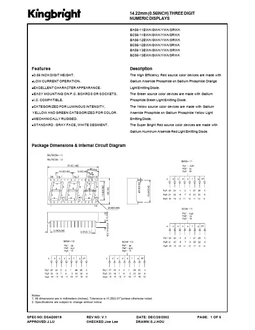
恒温加热器使用说明书一、产品介绍恒温加热器是一种用于控制温度的设备,适用于实验室、工业生产等领域。
本产品采用先进的温度传感器和控制技术,能够实现精确的温度控制,具有稳定性好、操作简单等特点。
二、安全注意事项1. 本产品需在干燥、通风良好的环境下使用。
2. 请确保电源连接正确,接地可靠,以确保使用安全。
3. 仔细阅读产品说明书,并按照说明进行正确操作,避免不必要的事故发生。
4. 使用过程中应避免遮挡散热孔,避免过载使用。
5. 使用结束后,请拔掉电源插头,确保设备断电。
三、产品特点1. 温控范围广:本产品的温控范围可根据需要进行调整,满足不同的实验需求。
2. 温度稳定性好:经过精确的温度控制算法设计,保证设备稳定运行,提供精确的温度控制。
3. 操作简单:本产品采用触摸屏设计,界面简洁清晰,操作便捷,即使对设备不熟悉的用户也能够轻松上手使用。
4. 故障自诊断:设备具有故障自诊断功能,一旦出现故障,会自动报警并显示故障原因,方便用户快速排除故障。
四、使用方法1. 打开设备:接通电源后,按下电源按钮,待设备开机完成后进入待机状态。
2. 设置温度:通过触摸屏上的温度调节按钮,可自定义所需温度。
设定后,系统会根据设定值进行温度控制。
3. 启动加热:设定好温度后,点击启动加热按钮,设备将开始加热,并根据设定温度进行温度调节。
4. 监控温度:设备运行时,观察触摸屏上显示的实时温度值,确保温度始终在设定范围内。
5. 结束使用:使用完毕后,点击停止加热按钮,设备会停止加热并保持待机状态。
拔掉电源插头,确保设备断电。
五、故障排除1. 故障自诊断:设备出现故障时,会自动报警并显示故障原因,用户可根据报警信息进行故障排除。
2. 联系售后服务:若设备故障无法解决,请联系售后服务中心进行维修或更换。
六、维护保养1. 定期清洁:使用过程中请保持设备干燥,避免积尘。
定期用软布擦拭设备外壳,以保持清洁。
2. 防止碰撞:使用过程中请避免撞击设备,以免损坏设备外壳或内部元件。
MCTRL R5Independent ControllerProduct Version:V1.0.1Document Number: NS110100550User ManualXI 'AN N OVA S T AR T EC HCO .,L T D.Copyright © 2018 Xi’an NovaStar Tech Co., Ltd. All Rights Reserved.No part of this document may be copied, reproduced, extracted or transmitted in any form or by any means without the prior written consent of Xi’an NovaStar Tech Co., Ltd.Trademarkis a trademark of Xi’an No vaStar Tech Co., Ltd.StatementYou are welcome to use the product of Xi’an NovaStar Tech Co., Ltd. (hereinafter referred to as NovaStar). This document is intended to help you understand and use the product. For accuracy and reliability, NovaStar may make improvements and/or changes to this document at any time and without notice. Any problem in use or any good suggestion, please contact us through ways provided in the document. We will do our utmost to solve the problems and adopt the suggestions after evaluation as soon as possible.X I'A NN OV AS TA RT EC HC O.,LT D.User Manual Change HistoryChange HistoryX I'A NN OV AS TA RT EC HC O.,ContentsChange History ................................................................................................................................ ii 1 Safety ............................................................................................................................................... 1 2 Overview ......................................................................................................................................... 2 3 Hardware Structure.. (3)3.1 Appearance .................................................................................................................................................. 3 3.2 Dimensions .. (5)4 Homepage ....................................................................................................................................... 6 5 Menu Operations .. (8)5.1 Brightness Adjustment ................................................................................................................................. 8 5.2 Screen Settings ........................................................................................................................................... 8 5.2.1 Quick Configuration .................................................................................................................................. 8 5.2.2 Advanced Configuration ........................................................................................................................... 9 5.2.3 Image Offset ............................................................................................................................................. 9 5.3 Rotation Settings ....................................................................................................................................... 10 5.4 Input Settings ............................................................................................................................................. 10 5.4.1 Input Video Source Settings ................................................................................................................... 10 5.4.2 Input Resolution Settings ........................................................................................................................ 10 5.5 Display Control ........................................................................................................................................... 11 5.6 Advanced Settings ...................................................................................................................................... 11 5.6.1 Mapping Function .................................................................................................................................... 11 5.6.2 Loading Cabinet Files .............................................................................................................................. 11 5.6.3 Alarm Threshold ...................................................................................................................................... 12 5.6.4 Saving to Hardware ................................................................................................................................ 12 5.6.5 Redundancy ............................................................................................................................................ 13 5.6.6 Preset Template ...................................................................................................................................... 13 5.6.7 Hot Backup for Input Source .................................................................................................................. 13 5.6.8 Factory Reset ......................................................................................................................................... 13 5.6.9 Go Homepage (s) ................................................................................................................................... 13 5.6.10 Greyscale Adjustment ........................................................................................................................... 13 5.6.11 Hardware Version ................................................................................................................................. 13 5.7 Communication Settings ............................................................................................................................ 13 5.8 Language (14)XI 'AN NOVA S T AR T EC HCO .,L T D.6 Specifications (15)X I'A NN OV AS TA RT EC HC O.,LT D.User Manual 1 Safety1 SafetyTo avoid potential hazards, please use this product according to regulations. Poweroutlet should be installed near the unit and easy to reach. In the event of breakdowns,only trained personnel may disassemble it for maintenance, and please contact theafter-sales department of NovaStar for help.High-voltage hazard: Operating voltage of this product ranges from 100V to 240 V AC.Grounding: Ground connection of this product is enabled through powercords. Please make sure that ground conductors are in good condition.Electromagnetic interference: Keep this product far away from magnets,motors and transformers.Moisture proof: Keep this product in a dry and clean environment. Incase of liquid immersion, please pull the power plug out immediately.Keep the product away from flammable and explosive hazardoussubstances.Prevent liquids or metal fragments from dropping into the product inorder to avoid accidents.X I'A NN OV.,LT D.User Manual 2 Overview2 OverviewDeveloped by NovaStar, the MCTRL R5 is the first independent controller thatsupports rotation function. With up to 3840×1080@60Hz loading capacity of a singleunit, it can support any custom resolution within this range as required, thus meetingthe on-site configuration requirements of extra-long or extra-large LED displays.The MCTRL R5 supports HDMI, Dual Link DVI, SDI signal inputs, as well as 8Neutrik Gigabit Ethernet ports, and 2 optical fiber outputs.The distinctive and innovative design of the MCTRL R5 enables screen configurationwithout PC, diverse image rotation effects, and amazing visual experience for users.Note: The device must be powered off before connection.To control multiple MCTRL R5 units (10 units at most), please cascade them according to the figure below.X I'A NN OV AS TA RT EC HC O.,LT D.3Hardware Structure3.1 AppearanceFront PanelInstruction on knob operations:On the home screen, pressing the knob enters the main menu.XI 'AC HCO .,L T D.● On the main menu, rotating the knob selects a menu item or adjusts theparameter, and pressing the knob confirms the selection or enters the submenu. ●Holding down the knob and BACK button simultaneously for 5 seconds locks or unlocks all the buttons.Rear PanelNote : Type-A USB port is prohibited from being connected to the upper computer directly.XI 'A3.2 DimensionsUnit: mmX I'A NN OV AS TA RT EC HC O.,LT D.4HomepageAfter the MCTRL R5 is powered on, the home screen is shown in the figure below.Power voltage of the motherboard Temperature inside the deviceScreen brightnessXI 'AA S T AR T E C HCO .,L T D.1~2 Optical fiber ports connection: ●●//Control ports:Connects to USB/ Ethernet/ GenLock synchronization/Rotation enabled/lockedX I'A NN OV AS TA RT EC HC O.,5 Menu OperationsMCTRL R5 features powerful functions and simple operations. To achieve betterdisplay effects, users can choose to set other options in the menu.5.1 Brightness AdjustmentOn the main menu, press the knob to select the Brightness item and rotate the knobto adjust the brightness value.5.2 Screen Settings5.2.1 Quick ConfigurationBefore you start, load the cabinet configuration files and save them to the receivingcard.Step 1 Press the knob to enter the main menu.Step 2 Choose Screen Settings > Quick Config to enter the submenu, and rotate the knob to set corresponding options.●Set the row and column quantity of cabinets based on the actual condition of ascreen.●Set the cabinet quantity connecting to port 1. There are limits on the loadingcapacity of ports. Refer to a) in Note for details.●Set data flow of the screen, and refer to c), d), and e) in Note for details.X I'A NN OV AS TA RT EC HC O.,LT D.5.2.2 Advanced ConfigurationStep 1 Choose Advanced Config and press the knob to enter its submenu.Step 2 On the warning screen, click Yes to enter the advanced configuration screen. Step 3 Select Enable and set the parameters of targeted Ethernet ports.5.2.3 Image OffsetSet the horizontal offset and vertical offset of devices ’ loading image.XI 'AN N OVA S5.3 Rotation SettingsThere are 2 rotation methods: Port rotation and screen rotation.●Port rotation: Rotation of cabinets loaded by an Ethernet port (For example, set the rotation angle of port 1, and the cabinets loaded by port 1 will rotate according to the angle).●Screen rotation: Rotation of the whole LED screen according to the rotation angle set before.Rotation settings:Step 1 Choose Rotation Settings > Rotation Enable , and choose ENABLE . Step 2 Choose Port Rotate or Screen Rotate and set parameters. Step 3 Select Save to save your settings.Notes:● Hardware screen configuration is required to be done before the rotation settings. ●After screen configuration are done on SmartLCT, set rotation function on MCTRL R5, and a message “Reconfig screen . Are you sure?” will appear. Choose Yes to perform rotation settings.5.4 Input Settings5.4.1 Input Video Source Settings There are several types of input sources available for users to choose.5.4.2 Input Resolution Settings There are 2 methods to set input resolution:Method 1: Preset resolution Choose a proper resolution from the preset standard resolutions, or use method 2 tocustomize the resolution.Method 2: Custom resolutionRotate the knob to set the custom width (growing in even numbers), custom height, and custom refresh rate, and choose Apply . Press the knob to confirm the setting. If Apply is not enabled, the custom resolution is invalid.XI 'A N N O V A S T AR T EC HCO .,L T D.5.5 Display ControlNormal: Playing the input source normally. Black Out: The screen is black out, with no display. Freeze: Freezing the displaying image.Test Pattern: 8 test patterns including pure color and lines testing.Image Settings: Setting red, green and blue brightness, color temperature, Gamma rate, and saving parameters.5.6 Advanced SettingsAdvanced settings include settings of multiple main functions, as shown below.5.6.1 Mapping FunctionWhen Mapping Function is enabled, each of the cabinets will display the cabinet number and Ethernet port number it belongs to.5.6.2 Loading Cabinet FilesConnect to PC and start NovaLCT on PC, and import the saved cabinet configuration files.Step 1 Save cabinet configuration files.After configuring the receiving cards, click Save to File to save the cabinet configuration files (.rcfgx) to local PC.XI 'AN N OVA S T AR T EC HCO .,L T D.Step 2 Import the cabinet configuration files to the MCTRL R5.Note: After entering the Configuration File of Controller Cabinet Import window, NovaLCTwill automatically read the configuration files already existed in the MCTRL R5. Users can change the names and orders of these files or delete them.Step 3 Load the cabinet configuration files.5.6.3 Alarm ThresholdSet the ranges of temperature and voltage values.5.6.4 Saving to HardwareSave all the configurations related to the receiving cards to the receiving cards and those data will not be lost even after the device is powered off.XI 'AN N OVA S T AR T EC HCO .,L T D.5.6.5 RedundancySet the current device as the primary or backup device.5.6.6 Preset TemplateSave configuration information, rotation parameters, and user settings information astemplates. Users can add 10 templates at most.5.6.7 Hot Backup for Input SourceSet backup source for the current input source. The backup source should be othertypes of input source supported by the device.5.6.8 Factory ResetReset the current device to factory settings.5.6.9 Go Homepage (s)The current page stays for how many seconds before going homepage when there isno actions.5.6.10 Greyscale AdjustmentAdjust greyscale among the range from 4 to 15 for the LED display screen.5.6.11 Hardware VersionView the hardware version of current device. In case of new version release, accessNovaLCT through PC to upgrade the hardware version.5.7 Communication SettingsSet the communication mode and network parameters.Two communication modes are provided: USB Preferred and LAN Preferred. When the USB and Ethernet ports are connected at the same time, the system will use the communication mode set by the user.X I'A NN OV AS TA RT EC HC O.,LT D.Network settings include manual mode and auto mode. When setting the networkmanually, the IP address of current device cannot conflict with IP addresses of otherdevices.5.8 LanguageChange the UI language of the MCTRL R5 unit.X I'A NN OV AS TA RT EC HC O.,LT D.User Manual 6 Specifications6 SpecificationsX I'A NN OV AS TAD.。
Klimat58787516S40,V4001-Petrol30618095-1Diesel3730340-1 20000excl.AT Petrol30618095-1 -99excl.2.0T AT,T4AT Petrol30618095-1 +Time controlling the heater,see p.3.Digital timer,type43544554-3 A fuel-driven parking heater ensures that the car is warm when you need it,irrespective of where it is parked.Starting an engine that is already warm means:•the car will emit less noxious exhaust gases.•the passengers sit in a warm car,reducing the risk of catching a cold,•there is no need to scrape ice from windows,•the car consumes considerably less fuel,•engine wear is reduced.A new generation of heater has been introduced in the912-B.This heater is lighter and smaller than previous heater091-B. The control module is optimised for efficient combustion.AccessoriesRemote start TP41,see p.4.8787516S40,V40Digital timer for time setting or manual starting(direct start)and for switching the heater off.Easy to set,even in the darkas the LCD display is back-lit.The timer displays a24hoursetting and can be used as a clock.Digital timer,type43544554-3Functions:Digital timer,type4•Installed in the glove compartment.•Setting the departure time.The timer reads the temperatureand calculates the start time of the heater to reach thecorrect temperature for departure.•Two start times can be preprogrammed.•Start and shut-off.The heater switches off after one hourif not switched off manually.•LEDs which indicate if the timer is active and if the heateris operating.•Can be combined with remote start,see p.5(SE and NOonly).•No other timer is required.Replacement partsInstructionmanualDigital timer,type45929571-78787514Remote start8685694-5The heater can be controlled using the remote control with areceiver in the car and a small transmitter.The remote control can be indispensable on cold winter dayswhen you do not want to go out to the car to switch on theheater Easy to carry due to its small design.The heater is started by a short button press and is connectedfor a pre-set time.If the heater is to be disconnected at anearlier time,simply press the off-button on the remote control.Suitable for both fuel-driven and electric heaters.Technical dataRange TP41Up to600m if unimpededFrequency434MHzBattery transmitter Three x micro1.5V/AAA/LR03Transmitter dimensions114x50x24mm-20–+60°COperating temperaturetransmitterOperating temperature,-40–+75°CreceiverImportantSuitable only with digital timer,type4.8787514S40,V40Receiver SE3729605-0NO3730078-7Warm and environmentally friendly car by means of atelephone call!A product that enables you to make even betteruse of your fuel heater.It is often the case that a departure timehas been forgotten to be set.Perhaps the time of departure isnot known.You can now phone your car,for example,on theway to the airport just before takeoff.When you arrive your carwill be warm.You only need to take out your phone and call!You can switch off the heater in the same way.The system is based on a Mini-call receiver connected to thedigital timer,type4.Only function on certain markets.It is possible to retrofit on cars already equipped with a heater.ImportantSuitable for all cars with a fuel-driven heater and digi-tal,type4.8787613S40,V4001-Relay8685637-4This accessory allows you to set a start and a stop time for anelectric engine or passenger compartment heater.Facts and Advantages•No other timer is required.•Can be combined with remote start,see p.4.ImportantC not be combined with Fuel-driven heater912-B,912-D.Op.no.S40,V40With an electrical engine block heater and cabin heater,thecar is warm to sit in when it is cold outside.Starting an already warm engine subjects the engine toless wear,uses far less fuel and therefore reduces harmfulemissions.Information for the230-volt systemIt is a complete kit,consisting of a heater element whichisfitted to the engine and a small front hatch.The smalldimension of the front hatch ensures:•Simpler installation.Drilling a single hole•No sawing or other machining required.•Separate kits for the front engine block heater socket notrequired.•It is easier to position both aesthetically and ergonomically.•Simple design.The system can be supplemented easily with the passengercompartment connector socket.ImportantThe ideal preheating time with an electric engineheater is2-3hours.This is enough to raise the tem-perature of the engine to30-50°C above the outsidetemperature.After that the temperature does notincrease and the electric current(and your money)isused only to maintain the temperature.Output:500W.878765287656S40,V40Complete kitEU,230V()Petrol engines00-excl.GDI9162171-4GDI9499644-4 -99excl.GDI30883201-3 GDI9499644-4 Turbo30883202-1 Diesel engines01-8682350-7 -009499645-1 US,CA,110VPetrol engines(grounded switch)8670956-5Accessory(230V EU,()Passenger compartment connector socket,incl.Y connector GDI,turbo,diesel9499646-9 Petrol9499646-9 Passenger compartment unit,1500/600W9451735-6 (see p.9.)Connection cable2.5m(included in the above kits)9451508-7 5m9451649-9 Remote start TP41(see p.4.)Digital timer(see p.6.)8789991S40,V40,US,CA1500/600W9451735-6 The passenger compartment unit is placed on thefloor by the passenger seat.One of two power settings can be selected,1500or600 watt.The output is adjusted automatically to suit the outside temperature to minimise energy consumption.Facts and Advantages•Connected to the passenger compartment connector socket or other grounded socket.•Approved for use in moist environments and at low temperatures.•Suitable in combination with an electric engine heater.•The passenger compartment unit should not be left inside the passenger compartment while the car is being driven, since it may cause injuries during sudden braking or if the car is involved in an accident.•Unnecessary idling is avoided if windows are defrosted.This also reduces damage to the environment.The following power settings should be used,depending on the fuse size:Current supply fused with6A(1320W)Up to600W,also in combination with engine block heaters. Current supply fused with10A(2200W)Up to maximum setting1500W,also in combination with engine block heaters.Replacement partsThermal fuse kit9481278-1 ImportantFan heaters designed for use indoors must not be used in cars.7789991S40,V4001-30664131-7Fits tyre dimensions:•195/60R15•205/55R15•205/50R16Max.speed:50km/hour.A snow chain specially developed for larger tyre dimensionsThis type of snow chain has the advantage of not beingfittedon the inside of the tyre and does not take up the spacerequired by larger tyres.TÜV approved.Facts and Advantages•One pair,ready tofit.•Easy tofit.•Spare links included.Replacement partsHandle3529438-8Protective cover3529448-8Adapter,21mm30623786-8ImportantStandard snow chains cannot be used on wheels oflarger dimensions due to lack of space(risk of dam-aging the wheel housing etc.).These chains must beused instead.7789991S40,V40Fits tyre dimensions:205/50R15,205/45R1630862800-7205/55R151********-7195/60R15US30889647-1Maximum speed50km/h.A snow chain with narrow links specially developed for largertyre dimensions for the S40,V40.Facts and Advantages•Extremely compact links(3.1x10;traditional dimensions4x12)which are heat treated to maintain the same servicelife as traditional snow chains.•Fast and easy installation using the ring mechanism.•Reversible for increased service life.•Packed in a durable bag;ready for use.ImportantStandard snow chains cannot be used on wheels oflarger dimensions due to lack of space(risk of dam-aging the wheel housing etc.).These chains must beused instead.1Can not be used on cars equipped with chassis kits.117789991S40,V40Fits tyre dimensions:01-205/50R1630889098-7175/65R1430816222-1185/65R143472033-4185/65R15,195/60R159166342-7195/55R1530816224-7The quick installation snow chains are made of high gradegalvanised steel.Facts and Advantages•Prepacked in plastic bag,with installation instructions.•Can befitted in a couple of minutes.ImportantStandard snow chains cannot be used on wheels oflarger dimensions due to lack of space(risk of damag-ing the wheel housing etc.)For suitable snow chains.12。
INSTALLATION SHEET601011CHSingle LED Lamp Vanity19054 28th Avenue Surrey, BC Canada V3Z 6M3T: 604 538 7162 TF: 1-855 85 KUZCO F: 604 538 7196 W: 201503311.Remove the fixture from its original packaging. Remove the canopy mounting plate from within the canopy and attach it to the electrical junction box, and wall, using the screws provided in the hardware package.2.Attach the canopy to the mounting plate, which is attached to the electrical junction box on the wall. First attach all wiring with the provided marrets (white to white “N”, black to black “L”, ground to ground “G”). Push the canopy onto the mounting plate, then insert the screw into the holes on the top and bottom of the canopy, once inserted, screw in the screws provided to secure the fixture to the wall.3.Install the glass light cover onto the fixture. Take the glass light cover and guide it gently onto the fixture. Carefully turn the glass light cover in a clockwise motion in order to screw it firmly into place (do not over tighten).4.You have now completed the installation of your fixture, please enjoy.Please Note:• All Kuzco LED fixtures come with pre-wired LED module(s).• Unless instructed to do so, please do not touch any part of the LED module(s) as any unnecessary contact with the module could cause permanent damage.• For dimming, an ELV (Electronic Low Voltage) dimmer is required.3.1.2.。
OPERATING INSTRUCTIONS Works With Your Existing Roll-In Combi Rack or Trolley Brand and Model of Rack or Trolley was specified at time of order to assure docking alignment and cabinet compatibility.Any Variation of Heated Holding Companion HHC ModelsHEATED HOLDING COMPANIONRack Shown For Example Only Rack Shown For Example OnlyFWE Heated Holding Cabinet Temperature Range 90°F to 190°F1FWE TOP MOUNT HEAT SYSTEM ON/OFF Rocker Switch Heat Cycling Indicator Light (Amber)Temperature Setting Power Indicator Light (Green)Thermometer Works With Your Existing Roll-In Combi Rack or TrolleyRack or Trolley Sold Separately.Brand and Model of Rack or Trolley was specified at time of orderto assure docking alignment and cabinet compatibility.Racks Shown For Example Only2CONGRATULATIONS......and thank you for purchasing an FWE Top Mount heated holding cabinet. Your unit has been designed and manufactured under rigid controls to assure you the most efficient service. It is a full time unit,and may be used continuously.Please take a moment to read through this booklet of important information pertaining to your cabinet. By following a routine of proper use and care described on the following pages, your cabinet will last for many years.IMPORTANT: Your Manufacturer Registration Card must be returned within 30 days after initial delivery to activate the warranty.T he control panel is equipped with an adjustable thermostat (to 190°F) for temperature selection, an operational rangethermometer to show the actual internal temperature of the cabinet, a 20 amp ON/OFF rocker switch, a green power indicating light to tell you when the cabinet is “ON”, and an amber indicating light that illuminates when the heating element is activated and cycling.Your cabinet may have been custom ordered with Protected Security Controls or Hidden Controls which are pre-set at factory.FILL OUT REGISTRATION CARD CONTROL PANELINSTALLATION AND CARESERIAL AND MODEL NUMBERThese numbers are found on the nameplate (serial tag) affixedto the rear of the unit. Please record them in this booklet,in the space provided on page 9. When ordering parts and/orservice, you will need to provide this information. The voltageand amperage of the unit are also stamped on the serial tag.UNPACKINGAfter uncrating your cabinet, remove all tape and padding whichheld all doors, shelves, racks, cord, etc., in place during shipment.ELECTRICAL REQUIREMENTS AND GROUNDING FWE standard models operate on 110/120 volt, 60 Hz, 1 ph, A.C.(unless ordered otherwise), and are equipped with a three pronggrounding cord plug for your protection against possible shockhazards. Be sure to plug only into a properly grounded three prong wall receptacle. If you have any questions with regard to adequate wiring or grounding in your building, a qualified electrician should be contacted before using your cabinet. The amperage of your cabinet is stamped on the serial tag attached to the unit.DO NOT, UNDER ANY CIRCUMSTANCES, CUT OR REMOVE THE GROUNDING PRONG FROM THE CORD PLUG.WARNING: ONLY A QUALIFIED ELECTRICIAN SHOULDATTEMPT TO REPAIR OR REPLACE ELECTRICALCOMPONENTS OR WIRING.BE SURE THAT MODEL IS UNPLUGGED FROM ELECTRICAL SOURCE BEFORE REMOVING CONTROL PANEL.3FWE TOP MOUNT HEAT SYSTEM4Keep your cabinet clean by simply wiping the interior and exterior, as needed, with a damp cloth or sponge and a mild soapy solution.NEVER USE ABRASIVES, ACIDS, ORSTRONG CLEANERS.Do not flood or allow electrical parts to become wet. The interior tray slide assemblies and humidifier pans are removable for easy cleaning. A stainless steel cleaner/polish is recommended for the exterior to maintain a "like-new" appearance.DO NOT USE WAX OR STRONG CLEANERS ON DOOR GASKETS OR VINYL TRIM.CLEANINGCLEANING CARE AND MAINTENANCE YES!USE THESEPRODUCTS7FWE TOP MOUNT HEAT SYSTEMFOOD SAFETY CAUTION: HOLDING FOOD AT TEMPERATURES OF LESS THAN 140°F MAY BE DANGEROUS.TEMPERATURES UNDER 140°F PROMOTE THE GROWTH OF HARMFUL BACTERIA AND TOXINS IN SOME FOODS.160 ––150 ––140 ––130 ––120 ––110 ––100 ––90 ––80 ––70 ––60 ––50 ––40 ––30 ––20 ––10 ––0 ––– 70– – 60– – 50–– 40–– 30–– 20–– 10– – 0–– -10–– -20°F °CBacteria Reproduce Rapidly Bacteria Survive and Grow !TEMPERATURE DANGER ZONECheck this list first before you call for service...PROBLEM POSSIBLE CAUSE REMEDYTEMP TOO HOT TEMP NOT HOT ENOUGHNO HEAT AT ALL 1A] Adjustable thermostat set too high 1B] Thermostat needs re-calibrating**2A] Opening door unnecessarily 2B] Thermostat set too low 2C] Cord plug pulled out from outlet 2D] Fuse blown - no power to outlet 2E] Thermostat out of calibration**3A] Cabinet not plugged into outlet 3B] Thermostat knob at “ OFF ”3C] Rocker switch at “ OFF ” position 3D] Fuse Blown - no power to outlet 3E] Thermostat needs replacing 3F] Heating element burned out*1A] Set thermostat at a lower temperature (no lower than 140°F).1B] Loosen screw in thermostat knob and remove knob.Adjust set screw in hollow stem with small bladescrewdriver by turning CLOCK-WISE.1/4 turn lowers temperature approximately 10°F.DO NOT REMOVE SET SCREW.2A] Keep door closed and latched shutas much as possible.2B] Set thermostat at a higher temperature.2C] Replug cord into proper outlet.2D] Have a qualified electrician check powerand fuse box.2E] Loosen set screw in thermostat knoband remove knob. Adjust set screw in hollow stemwith small blade screwdriver by turningCOUNTER-CLOCKWISE.1/4 turn raises temperature approximately10°F. DO NOT REMOVE SET SCREW.3A] Plug cabinet into properly grounded electrical outlet.3B] Adjust thermostat knob to temperature setting required.3C] Turn switch to “ ON ” position.3D] Have a qualified electrician check power to fuse box.3E] Unplug cabinet from electrical source. Loosen set screw in thermostat knob and remove knob. Remove control panel, disconnect wires fromterminals on thermostat, and remove 2 screwsholding thermostat to control panel. Replacethermostat with new one, and re-install controlpanel and thermostat knob.3F] Unplug cart from electrical source. Remove screws holding heating element in place. Gently pullelement away from back wall a few inches toexpose wire connections. Disconnect wires, andreplace element with new one. Reconnect wires,secure element with screws.* * NOTE: CALIBRATION IS EXCLUDED FROM FWE WARRANTY. Thermostats on all units are calibrated at the factory * * prior to shipping. Due to conditions in transit, beyond our control, occasionally units will need to be re-calibrated prior * * to use. This is a simple procedure for which instructions are given above. (1B, 2E)* Heating element will either function or not function. Only a slight warmth indicates a problem with the thermostat, * not the element.8SERVICE RECORDModel Number ______________________Serial Number ______________________Date of Purchase ______________________Notes:___________________________________________________ ___________________________________________________ ___________________________________________________ ___________________________________________________ ___________________________________________________ ___________________________________________________ ___________________________________________________ ___________________________________________________ ___________________________________________________ ___________________________________________________ ___________________________________________________ ___________________________________________________ ___________________________________________________ ___________________________________________________ ___________________________________________________ ___________________________________________________ ___________________________________________________ ___________________________________________________ ___________________________________________________ ___________________________________________________ ___________________________________________________ ___________________________________________________ ___________________________________________________ ___________________________________________________ ___________________________________________________ ___________________________________________________ ___________________________________________________ 9FWE TOP MOUNT HEAT SYSTEMLIMITED TWO YEAR WARRANTYFWE / Food Warming Equipment Company, Inc.(Seller) warrants to the original purchaser, subject to the exceptions and conditions below, that FWE manufactured equipment shall be free from defects in material or factory workmanship, under ordinary use for the purpose for which it is designed. The effective warranty period is as follows:PARTS: Seller will furnish without charge to the original purchaser, FOB Sellers’ factory, replacement parts for repairs to all new stand ard catalog prod ucts and factory custom / modified units, which in Seller’s sole judgement, prove defective in materials or workmanship under normal and proper use with the reserved right to request the return of any part claimed to be defective, prior to issuing replacement part or authorizing warranty service, for a period of two (2) years from date of original shipment from Seller’s plant, except for equipment used in a Correctional Environment / Facilities, which is warranted for a period of one (1) year from date of original shipment from Seller’s plant.LABOR:Seller’s labor warranty shall be performed by a Seller-approved Service Agency who must contact Seller to obtain a Warranty Service Authorization (WSA) number prior to performing any repairs. If service is required during overtime periods, the difference between overtime and standard labor rates shall be paid by the purchaser. Seller does not assume any responsibility for any charges not expressly authorized, incidental to the repair or replacement of equipment covered by this warranty, nor charges exceed ing, in Sellers sole jud gement, normal and customary amounts. Only approved travel charges will be allowed. Seller’s labor warranty shall be from the date of original shipment date from Seller’s plant for a period of one (1) year, except for equipment used in a Correctional Environment / Facilities which is warranted for a period of six (6) months.This warranty is for normal usage and does not apply to any product or parts thereof that have been misused, altered, or where Seller’s operating instructions or specific voltage is not observed; nor shall this warranty apply to defective products or parts resulting from accident following date of original shipment, nor extend to or cover removal, installation, reinstallation or calibration, or service calls or cost of repairs undertaken by a customer. This warranty is also subject to the following:1.] Customer returning the warranty registration card, accompanying Sellers originalshipment, to Seller within thirty (30) days of receipt;2.] Giving immediate notice of any allegedly defective part or product to Seller; and3.] Customer, at Sellers request, returning said defective parts or product to Seller.This is the sole warranty applicable to the merchandise. It is expressly understood that Seller’s liability hereunder is limited to the repair or replacement, at Seller’s option, of products or parts, defective materials or workmanship as provided above. Seller’s judgement as to the cause and nature of any d efect will be final.Seller shall in no case be responsible for special or con-sequential damages or any other obligation or liability with respect to products sold by Seller. This warranty, as stated above, applies to equipment installed in the Continental United States. FWE equipment installed outside the Continental United States shall carry parts coverage only. All labor costs are approved on a discretionary basis, based on like repairs in the Continental U.S. This warranty shall stand in whole or in part as allowed by law. Any exclusion of a part of this warranty, as may be allowed by law, shall not void balance of warranty.This is a limited warranty pursuant to the Consumer Product Warranties Act, 15 U.S. Code. section 2303.© 2003 Food Warming Equipment Co., Inc.© 2013 Food Warming Equipment Co., Inc. Errors subject to correction. All specifications subject to change without notice. Printed in USA.FWE Parts Department:Phone: 815 459 7500FAX: 815 459 7989Ops-Manual-HHCModelsWE OFFER SALES AND SERVICE WORLDWIDE Food Warming Equipment Company, Inc.P .O. Box 1001 • Crystal Lake, IL 60039-1001Manufacturing Facilities:5599 Highway 31 West • Portland, TN 37148***************。
Features• IP65/67 - Ingress Protection Rating• Meets Canada Food Inspection Agency standards • NSF and NEMA 4X Certified• Replaces 250 or 400 watt HID fixtures• Up to 50% energy savings compared to equivalent metal halide luminaire • 80+ CRI• Standard low voltage dimming (0-10V, 1%)Featured Options• Emergency battery pack • Motion Sensors• Ceiling-mount bracket • Stainless Steel Latches• Clear, textured polycarbonate lens with linear ribsOptical SystemLens is optically clear, impact resistant acrylic for maximum light transmission and longevity or optional UV stabilized polycarbonate lenses for maximum impact resistance. The sides have precise linear prisms and ends are frosted to reduce direct glare.MountingStainless steel V-hook with hook hangers are standard. Optional cable hangers and ceiling mount brackets are available.ConstructionMolded one-piece glass reinforced plastic housing. Continuous poured in place polyurethane gasket. Diffuser flange fits into the gasketed retention slot providing a continuous seal, and is held in place with white celcon retaining latches. Holes on each end are 7/8 inch nominal diameter and are provided with two EPDM rubber caps for connection and through wiring.FinishPre-painted steel geartrays.SuspensionSeveral suspended mounting accessories are available (See mounting accessories).ElectricalAll electrical components are CSA approved or UL listed. Long life LEDs coupled with high efficiency drivers provide quality illumination. Rated to deliver L80 performance > 60,000 hours. System efficacy >140 lumens per watt for standard units.Warranty5 year limited warranty. For complete warranty, click here:*Maximum ambient temperature, refer to lumens chart on page 2. See Mounting KIT00013 and KIT00006Consult installation guide for exact dimensions.Approvals• Approved to CSA and UL standards.• Tested to LM79 standards. Suitable for wet locations.• DesignLights Consortium ® Qualified.All configurations may not be DLC qualified. Check /QPL forqualified configurations.DimensionsTop ViewEnd ViewProduct DescriptionPremium-grade high or low bay IP67 LED luminaire. For use with indoor and outdoor applications where high-efficiency, high-performance and dust/water resistance is required. This luminaire’s glass reinforced polyester housing and acrylic lens makes it ideal for applications that require a high degree of ingress protection. Suitable for 1500psi Pressure spray down. Operating ambient temperature range is from -40° to55°C*. For use in wet locations.ApplicationsCanopies, Dusty and Damp locations, Food processing, Parking garage, Wet location,Gymnasiums.TA LACOMP WETLOCIP65IP67Order Key080L - 8000 120L - 12000 150L - 15000 180L - 18000 240L - 24000 120L - 12000 150L - 15000 180L - 18000 240L - 24000 300L - 30000Driver Options B39††Emergency Lighting Battery Pack(Voltage must be specified 120V, 277V, 347V, 480V)Housing Construction OptionsC16 Stainless Steel LatchesC18 Tamperproof LatchesLens Options(High Impact Acrylic is standard P05)P07 Clear Polycarbonate LensP67 High Impact Acrylic Frosted Smooth Molded LensPackaging OptionsK0 Bulk Pack/Pallet Packed and/or WrappedWiring OptionsV08 Flexible Cord Feed (Single Circuit Cord) 6-ft StandardV10(1) Hub Compact for 1/2” Threaded Pipe (3/4” OD) - 1 EndV10(2) Hub Compact for 1/2” Threaded Pipe (3/4” OD) - 2 EndV15 Liquid Tight Strain Relief (Not For XH)V32 Wiring 2-Circuit CordApproval and Rating OptionsXH Class I Zone 2 Groups IIC, IIB + H2, IIAZone 22 Groups IIB, IIA(Class I Div 2 Groups A, B, C, DClass II Div 2 Groups F, GClass III)T3C or T4Controls OptionsClick Here for wireless controls guide.V68 Microwave Occupancy SensorV82 IP65 Motion Sensor (For Wet Locations)Note: Supplied with 2 pc. of HAZLOC 1/2” Hubs and 1 pc. of 1/2” Thread Plug.Cord not available.†† Emergency battery packs have limited operating temperatures.If fixture is to be switched a 2 circuit cord V32 is advised. Consult factory.* Emergency battery pack is not available with Haz Loc (HX)** 90+ CRI reduces lumen output by 20%, not available with 5000KOther options may be available, consult factory. Specifications and datasubject to change without notice.48”EXAMPLE: LHBV48-LED840K180LUNV-P0724”KIT00001KIT00013KIT00006PhotometricsPerformance DataLifetime ExpectancyPerformance Scaling Factor。
Mounting Guide:Dash/Suction Cup or Swivel Mount BracketDominator™ TIR3™ Super-LED® Series©2004 Whelen Engineering Company Inc.Form No.13885B (061614)For warranty information regarding this product, visit /warranty•Proper installation of this product requires the installer to have a good understanding of automotive electronics, systems and procedures.•Whelen Engineering requires the use of waterproof butt splices and/or connectors if that connector could be exposed to moisture.•Any holes, either created or utilized by this product, should be made both air- and watertight using a sealant recommended by your vehicle manufacturer.•Failure to use specified installation parts and/or hardware will void the product warranty.•If mounting this product requires drilling holes, the installer MUST be sure that no vehicle components or other vital parts could be damaged by the drilling process. Check both sides of the mounting surface before drilling begins. Also de-burr the holes and remove any metal shards or remnants. Install grommets into all wire passage holes.•If this manual states that this product may be mounted with suction cups, magnets, tape or Velcro®, clean the mounting surface with a 50/50 mix of isopropyl alcohol and water and dry thoroughly.•Do not install this product or route any wires in the deployment area of your air bag. Equipment mounted or located in the air bag deployment area will damage or reduce the effectiveness of the air bag, or become a projectile that could cause serious personal injury or death. Refer to your vehicle owner’s manual for the air bag deployment area. The User/Installer assumes full responsibility to determine proper mounting location, based on providing ultimate safety to all passengers inside the vehicle.•For this product to operate at optimum efficiency, a good electrical connection to chassis ground must be made. The recommendedprocedure requires the product ground wire to be connected directly to the NEGATIVE (-) battery post (this does not include products that use cigar power cords).•If this product uses a remote device for activation or control, make sure that this device is located in an area that allows both the vehicle and the device to be operated safely in any driving condition.•Do not attempt to activate or control this device in a hazardous driving situation.•This product contains either strobe light(s), halogen light(s), high-intensity LEDs or a combination of these lights. Do not stare directly into these lights. Momentary blindness and/or eye damage could result.•Use only soap and water to clean the outer lens. Use of other chemicals could result in premature lens cracking (crazing) and discoloration. Lenses in this condition have significantly reduced effectiveness and should be replaced immediately. Inspect and operate this product regularly to confirm its proper operation and mounting condition. Do not use a pressure washer to clean this product.•It is recommended that these instructions be stored in a safe place and referred to when performing maintenance and/or reinstallation of this product.•FAILURE TO FOLLOW THESE SAFETY PRECAUTIONS AND INSTRUCTIONS COULD RESULT IN DAMAGE TO THE PRODUCT OR VEHICLE AND/OR SERIOUS INJURY TO YOU AND YOUR PASSENGERS!A u t o m o t i v e : Warnings to InstallersWhelen’s emergency vehicle warning devices must be properly mounted and wired in order to be effective and safe. Read and follow all of Whelen’s written instructions when installing or using this device. Emergency vehicles are often operated under high speed stressful conditions which must be accounted for when installing all emergency warning devices. Controls should be placed within convenient reach of the operator so that they can operate the system without taking their eyes off the roadway. Emergency warning devices can require high electrical voltages and/or currents. Properly protect and use caution around live electrical connections.Grounding or shorting of electrical connections can cause high current arcing, which can cause personal injury and/or vehicle damage, including fire. Many electronic devices used in emergency vehicles can create or be affected by electromagnetic interference. Therefore, after installation of any electronic device it is necessary to test all electronic equipment simultaneously to insure that they operate free of interference from other components within the vehicle. Never power emergency warning equipment from the same circuit or share the same grounding circuit with radio communication equipment. All devices should be mounted in accordance with the manufacturer’s instructions and securely fastened to vehicle elements of sufficient strength to withstand the forces applied to the device. Driver and/or passenger air bags (SRS) will affect the way equipment should be mounted. This device should be mounted by permanent installation and within the zones specified by the vehicle manufacturer, if any. Any device mounted in the deployment area of an air bag will damage or reduce the effectiveness of the air bag and may damage or dislodge the device. Installer must be sure that this device, its mounting hardware and electrical supply wiring does not interfere with the air bag or the SRS wiring or sensors. Mounting the unit inside the vehicle by a method other than permanent installation is not recommended as unit may become dislodged during swerving; sudden braking or collision. Failure to follow instructions can result in personal injury. Whelen assumes no liability for any loss resulting from the use of this warning device. PROPER INSTALLATION COMBINED WITH OPERATOR TRAINING IN THE PROPER USE OF EMERGENCY WARNING DEVICES IS ESSENTIAL TO INSURE THE SAFETY OF EMERGENCY PERSONNEL AND THE PUBLIC.Warnings to UsersWhelen’s emergency vehicle warning devices are intended to alert other operators and pedestrians to the presence and operation of emergency vehicles and personnel. However, the use of this or any other Whelen emergency warning device does not guarantee that you will have the right-of-way or that other drivers and pedestrians will properly heed an emergency warning signal. Never assume you have the right-of-way. It is your responsibility to proceed safely before entering an intersection, driving against traffic, responding at a high rate of speed, or walking on or around traffic lanes. Emergency vehicle warning devices should be tested on a daily basis to ensure that they operate properly. When in actual use, the operator must ensure that both visual and audible warnings are not blocked by vehicle components (i.e.: open trunks or compartment doors), people, vehicles, or other obstructions. It is the user’s responsibility to understand and obey all laws regarding emergency warning devices. The user should be familiar with all applicable laws and regulations prior to the use of any emergency vehicle warning device. Whelen’s audible warning devices are designed to project sound in a forward direction away from the vehicle occupants. However, because sustained periodic exposure to loud sounds can cause hearing loss, all audible warning devices should be installed and operated in accordance with the standards established by the National Fire Protection Association.Safety FirstThis document provides all the necessary information to allow your Whelen product to be properly and safely installed. Before beginning the installation and/or operation of your new product, the installation technician and operator must read this manual completely. Important information is contained herein that could prevent serious injury or damage.51 Winthrop RoadChester, Connecticut 06412-0684Phone: (860) 526-9504Internet: ®ENGINEERING COMPANY INC.Installation: Swivel Mount1.Attach the bail strap brackets to the swivel bracket using twoof the supplied 10-24 wiz nuts as shown (do not fully tighten yet).2.Mount the 4 carriage bolts with elastic stop nuts to the bailstrap bracket (do not fully tighten yet).3.Remove the endcap from the Dominator™, slide the 4carriage bolts on the bracket into the back and then replace the endcap.4.Place the unit with bracket in its mounting position on themounting surface. After the bracket has been adjusted for proper angle, windshield clearance, etc., tighten the wiz nuts and elastic stop nuts to secure the Dominator into the desired position.5.With the Dominator still in its mounting position, mark the 4mounting holes onto the mounting surface.6.Check both sides of the mounting surface to be sure that novehicle components or other vital parts could be damaged by the drilling process, then remove the Dominator and drill the 4 mounting holes using an appropriately sized drill bit.7.Mount the unit using the supplied 10-24 x 1” PPHMS and wiznuts and extend the cable to power. Refer to your Dominator manual for detailed wiring information.CAUTION: This product has been designed to rest on top of the vehicle’s dashboard. Suction cups are used to prevent lateral movement while the vehicle is in motion. These suction cups should not be used to suspend this product above the dashboard.WARNING! DO NOT MOUNT A DOMINATOR THAT HAS 3 OR MORE LIGHTHEADS TO A WINDSHIELD!WARNING! Do not install this product or route any wires in the deployment area of your air bag. Equipment mounted or located in the air bag deployment area will damage or reduce the effectiveness of the air bag, or become a projectile that could cause serious personal injury or death. Refer to your vehicle owners manual for the air bag deployment area. The User/Installer assumes full responsibility to determine proper mounting location, based on providing ultimate safety to all passengers inside the vehicle.Installation: Dash/Suction Cup Mount1.Attach the suction cups to the mounting bracket as shown.2.Mount the two carriage bolts to the bracket with the elasticstop nuts. (Do not fully tighten)3.Remove the endcap as shown and slide the 2 carriage boltson the bracket into the back of the Dominator™ then replace the endcap.4.Adjust the position of the bracket for horizontal light projectionthen tighten the two carriage bolts.5.Extend the cable to power. Refer to your Dominator manualfor wiring.。
Thermostatic Heater IllustrationI. Item description:∙Adopted by original Yudian Automation PDI economic type temperature controller, its high-accuracy, operation is safe, simple, clear and convenience.∙Adopted by original high-quality AC solid-state relay, long lasting as 100 times of the common contact relay.∙Adopted by multiple high-quality metal heating pipes, maintenance is convenience and low failure-rate.∙The aluminum top surface is high thermal conductivity, heat fast and evenly.∙The whole case is made by high-quality SUS304 stainless to ensure it against from rusted and peeling off in the usual condition.II. SpecfationPower Supply: 220V (50HZ);Controllable Temperature Range: Basic Type (Ordinary Temperature~350℃); Elevated Temperature Type( Ordinary Temperature~450℃), Ultra Temperature Type (Ordinary Temperature~500℃), Each type of the item has Unitary Type (Model A), Splitting Type (Model B) and Guardrail Type ( Model C).E,F。
III. Application filed∙Electronic industrial bonding sealing and application heating.∙LED industrial aluminum base welding and maintenance∙mold core pre-heating∙Essential equipment at the laboratory in various industrials such as biology, genetics, medicine and environment etc.IV. Application Instruction∙Plug in the power and turn on the POWER switch while the RED indicator light constant light, its means the device has being powered.∙Turn on the HEATING switch and the device is starting then, GREEN indicator light constant light, it’s means the device is h eating up; sparkling means it has been into the constant temperature while workstation is being recycle heating up.∙Once it finish using, please turn off the HEATING switch first and the device will be stopped heating, while the RED indicator light are still constant light in order toreminding the device are still working and please don’t touch the work surface. Waitfor the work surface being cool down (suggesting after an hour) and torn off thePOWER switch then.V. Attention:∙Voltage must be 220V, please use the 3 pole socket which is connect to the earth and with anticreeping switch as well.∙Please don’t open the case or switch any wire position unless you are the specific operation.∙Hand touch is prohibited in case to avoid burn.∙Please unplug the power supply when the people away or device has being long term idle.∙Please keep the vent hole clean since the device has been cooperated with fan cooler,∙Please make sure it has unplugged from the power source when the fuse needs to be replaced for safety.VII. Parameter Settingshowing at the display window under the default situation, press the key ∨ for value reducing, press the key ∧ for value increasing, the dot sparkly with the number which position switched( sparkly like cursor). Press down for quick increase / reduce value, and the value will be speed up while the position of the dot rightward switch. Press the key <to move and modify the position of the value (cursor). Press the key ∧ or ∨ to modify the value which is sparkly, control convenience.●Automatic adjustable (AT) operation, available with Automatic (AT) operating toconfirm the PID adjustable parameter when use AI agronomical PID control. The AT parameter shows up after press the key <at 2 seconds under the default situation.Press the key ∧ to modify the OFF to ON which is shown at the bottom displaywindow, the Automatic Adjustable operation will be start by press the key “O” toconfirm. At the same time, the letter “AT” will be sparking at the display window which is at the bottom of instrument panel, the result of the suitable PID parameter for the current condition will be counted automatically by the local micro CPU of theinstrument panel, and it will be exterminated automatically from the AT operating.Press the key <at another 2 seconds to switch up the AT parameter from ON toOFF and confirmed by press the key “0” to give up the AT operating. (Remarks: The system parameter value are totally different within the different set value, SV value modify are prohibited while the AT operating in process. The control result might be not the best once the AT operation finished, it will be got the best result after use in a whileNonstandard specification is available to booking with 5~7 working days lead-timeVIII, Guarantee●12 months guaranteed for the complete device (6 months for heating pipe) beyondhuman control.●Lifetime beneficial service after guarantee.Note:●Please make sure the connector plug is plug in fastened, no shaking movement,otherwise the power socket will be burned by the spark.●The temperature might be 3-5 degrees higher than the setting number and it willbe back to it after few minutes, this feature could be increase the uniformity ofheating panel temperature.●Since the heating panel is machined goods, there has some machine oil left atthe screw hole and it would be some smoke with smell comes up after burning bythe high temperature, this is normal phenomenon and will be disappeared after aperiod.●Please ignore the noise when this equipment running, it’s because of grating thatthe heating pipe rubs against with panel during the situation of substancesexpand when heated and contract when cooled.●There are 2 fuses inside the equipment to ensure the safety.●It has been took 24 hours for burn-in test before out-going of the factory, pleasedon’t change the default parameter without authorized,otherwise ourassociation will take no responsibility and liability.。