U1240 系列数字多用表技术资料
- 格式:pdf
- 大小:1.87 MB
- 文档页数:9
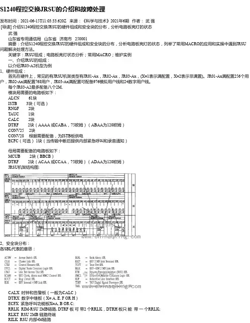
S1240程控交换JRSU的介绍和故障处理发布时间:2021-06-15T11:03:33.620Z 来源:《科学与技术》2021年6期作者:武强[导读] 介绍S1240程控交换JRSU的硬件组成和安全块的分布,分析电路板亮灯的状态武强山东省专用通信局山东省济南市 250001摘要:介绍S1240程控交换JRSU的硬件组成和安全块的分布,分析电路板亮灯的状态,列举了常用MACRO的应用和实操中遇到JRSU 问题解决处理方法。
关键字:JRSU组成;电路板亮灯状态分析;常用MACRO;维护实例一、介绍JRSU的组成:以介绍JR03-A2机型为例1、硬件组成:首先在硬件上,常见的有JRSU机架类型有JR01-Ax,JR02-Ax,JR03-Ax,(X=1表示满配置,X=2表示非满置)。
JR01-Ax满配置256个用户,JR02-Ax满配置768用户,JR03-Ax满配置可配备976模拟用户线和24数字用户线。
每个JR03-A2最多配备八个2M,模块局需要的电路板如下: ALCN 61块ISTB 3块(可选) RNGF 2块TAUC 1块CALC 2块DTRF 2块(AAAA 或CABA,75欧姆)(ABAA为120欧姆) CONV25 2块CONV28 根据需要配备,为ISTB板供电 ECFC(可选) 1块(当传输中断后提供内部紧急呼叫和录音通知)母局需要配备的电路板如下: MCUB 2块(BBCB) DTRF 2块(ACAA 或CCAA,75欧姆)(ADAA为120欧姆) JRSU机架结构图:2、安全块分布:各SBL代表的意思:CALX 时钟和告警板(一般为CALC) DTRX 数字中继板(X= A, E, F OR H) ECFX 紧急呼叫功能板X=A, B OR C; RRLK RIM-RSU 2MB链路, DTRF 板可带2 个RRLK,DTRH 板只能带一个RRLK; RLKT RSU 2MB 链路终端 RILK RSU 内部4M链路RCAM RSU 时钟告警和人机命令控制二、各电路板灯的状态:1、 DTRX-RIM 指示灯的说明(母局) LED1 & LED2 当RSU未被激活时,此两盏灯慢闪,当RSU活了之后,此两灯快闪; LED3 只有当进行PACKET SWITCHING 时,才闪动; LED4 指示LOOPA的状态熄灭没有告警常亮有告警慢闪此LOOP上没有RSU处于工作状态快闪此LOOP上至少有一个RSU处于工作状态 LED5 指示LOOPB的状态,说明同LED4; LED6 指示系统的不同工作状态熄灭普通工作状态常亮不正常的状态。
F S9721_L P3产品说明书4,000格数字多用电表专用集成电路.Rev. 2.0June 2006Fortune Semiconductor Corp.FS9721_LP1-DS-20_SC CR-004251台北县淡水镇中正东路二段27号28楼电话:886-2-28094742传真:886-2-28094874注 意1. 为了用好FS9721_LP3,请仔细阅读本说明书。
2. 本说明书提供的各应用电路图及各图中的组件规格,仅供参考,实际应用中电 路形式、组件规格和参数要根据各具体情况而定,才能保证达到设计要求。
3. 用FS9721_LP3作测量仪表时,要注意各输入端的过电压、过电流保护,以免 在过电压、过电流情况下造成FS9721_LP3和仪表的损坏。
4. 本器件的“自动关机”,是指一种休眠状态,在休眠状态下,仍要消耗微小的 电流(小于5μA),若长期不用,最好切断电源。
5. FS9721_LP3是带微处理器的高精度、多功能模/数变换器,应用FS9721_LP3 时PCB 的设计、元器件的摆放要考虑抗干扰的措施,尽量减少外部引入的干 扰和内部的交叉干扰,以期求得满意的效果。
6. 随着产品的改进和提高, 本说明书有些参数和电路会有些变动,变动时,恕不另行通知,若有问题,请直接与本公司联系。
目 录一、简介 (4)二、FS9721与FS9711的异同点 (4)三、特征 (4)四、可测量种类 (4)五、可应用产品领域 (5)六、方框图 (5)七、脚位图 (5)八、脚位描述 (6)九、技术规格 (7)十、测量种类选择 (9)十一、按键定义 (10)十二、其它功能 (10)十三、应用说明 (11)十四、RS232传输协议 (18)十五、液晶显示器及波形 (19)十六、封装片外形及裸片尺寸 (20)十七、采购信息 (21)十八、更新纪录 (22)一、简介FS9721_LP3是高性能、低功耗、3 3/4位(4000 Counts)带微处理器的模/数变换器(ADC+MCU),内部包含有8位微处理器,低噪声、高稳定运算放大器,交流整流运算放大器,电压提升电路及稳压电源,高稳定带隙基准电源,自动量程转换及功能控制电路,蜂鸣器驱动电路,时钟振荡电路,背光显示控制电路,液晶显示驱动电路等。
HP34401A数字多⽤表第⼀章 HP34401A数字多⽤表HP34401A 数字多⽤表是具有6 1/2数字显⽰、⾼性能的数字式万⽤表。
它将台式仪器的整体性能融为⼀体,为我们进⾏电量测量提供多种不同的测试⽅案,使我们获得满意的测量结果。
构制⾼精度的测量●测量直流电压、直流电流、电阻:设置6位的数字分辨率(使⽤6位数字慢模式可进⼀步减⼩测量燥声)。
对于100mA, 1V,和10V量程,设置输⼊阻抗⼤于10 GΩ,可获得最好的直流测量精度。
使⽤4线电阻测量可获得最⾼的电阻测量精度。
使⽤数学归零测量2线导线电阻,在直流电压测量时,并可消除互连偏置的影响。
●测量交流电压、交流:设置6位的数字分辨率选择低通交流滤波器 (1 Hz to 300 kHz)●测量频率和周期:设置6位的数字分辨率⽅便的台式仪器特性●清晰的真空荧光显⽰器●内设数学运算功能●连续测试及⼆极管测量功能●⽆需⼿动、读数保留特性●可携带、⽆台架的厚实外壳灵活的系统特性●HP-IB (IEEE-488) 接⼝标准配制●RS-323 接⼝标准配制●标准程控语⾔包括: SCPI, HP34578A, and FLUKE 8840.●读取速率⾼达1000 个/每秒●存储量可达512个读数●极限测试,并有 pass/fail 信号第⼀节技术指标⼀.万⽤表的技术指标说明在这⼀节中,我们将介绍技术指标中的部分术语,以便对数字多⽤表的技术指标能更好的理解。
位数及超量程位数指标是数字多⽤表最基本的、⽽有时也是最容易混淆的特性。
位数等于数字多⽤表可以测量或显⽰出“9”的最⼤数量,这表⽰完整的位数数量。
但是,⼤多数多⽤表可以测量超量程的量值,即可再加上部分或“1/2”个位数。
例如,HP 34401A 设置在10V量程范围时,测量到 9.99999 VDC,这表⽰分辨率为6个完整的数位。
但是,该表也可以测量超过10V量程的范围,最⼤可以测量到12.00000 VDC. 这就是所谓超过20%的测量范围能⼒和6 1/2 位数的测量。
本文版权归原作者所有,仅供学习用。
第六章S1240 EC74版程控交换设备上海贝尔生产的S1240程控数字电话交换设备在中国通信网上已成功运行十几年,系统性能稳定,同时S1240程控交换设备不断在硬件和软件上升级换代。
S1240程控交换设备从硬件分为A型机、E型机和J型机;从软件版本分为35/42版、5x版、EC72版、EC74版等,对国家骨干通信网、本地市话网、国家智能网、省内智能网、NO.7信令网、综合业务数字网(ISDN)、用户接入网的发展起了重要的作用。
目前各交换局普遍使用的S1240程控交换设备是S1240 EC74版J型机,它具有NO.7信令功能、ISDN功能、智能网功能、接入Internet功能。
局间中继可采用TUP或ISUP,ISUP正在逐步替代TUP。
S1240内部的交换码率为4.096Mbit/s。
·6.1 S1240 系统结构上海贝尔生产的S1240程控数字电话交换设备在中国通信网上已成功运行十几年,系统性能稳定,同时S1240程控交换设备不断在硬件和软件上升级换代。
S1240程控交换设备从硬件分为A 型机、E型机和J型机;从软件版本分为35/42版、5x版、EC72版、EC74版等,对国家骨干通信网、本地市话网、国家智能网、省内智能网、NO.7信令网、综合业务数字网(ISDN)、用户接入网的发展起了重要的作用。
目前各交换局普遍使用的S1240程控交换设备是S1240 EC74版J 型机,它具有NO.7信令功能、ISDN功能、智能网功能、接入Internet功能。
局间中继可采用TUP或ISUP,ISUP正在逐步替代TUP。
S1240内部的交换码率为4.096Mbit/s。
6. 1 S1240系统结构S1240程控数字电话交换设备具有以下特点:①全数字化②全分布控制S1240系统的控制功能由分布在各个终端和辅助控制单元(ACE)中的微处理机共同完成。
采用全分布控制使得系统的处理能力可以适应不同容量和不同业务的需要。
S1240基础知识第一部分机型简介一、系统结构A1000 S12的功能结构非常简单,它由一个内部交换网络和连接在网络上的不同的模块所构成。
模块的类型和数量取决于交换局的容量和提供的业务. A1000 S12程控交换机的中心是交换网络,所有的模块通过PCM链路连接到网络上。
内部交换网络(又称数字交换网,简称DSN)由一系列按一定拓扑结构连接的交换单元构成,模块数目的增加和话务量的增长,将引起DSN交换级数和平面数的增加。
另一方面,所有模块通过PCM链路连接到DSN。
所有模块都包含一个结构相同的部份--控制单元(简称CE),控制单元由一个微处理器及存贮器,和一个连接交换网络的标准接口构成。
控制单元(CE)通常分为两类:终端控制单元(简称TCE)和辅助控制单元(ACE)。
终端控制单元(TCE)含有一个标准接口,这个接口与具有特定模块功能的终端电路相连,比如用户电路,中继电路等。
辅助控制单元(ACE)不含任何终端电路,主要用于完成一些特殊任务,比如:错误处理、字冠分析、本局用户标识。
下面简单介绍一些主要的A1000 S12模块:模拟用户模块(简称ASM):由一个控制单元和一组用户电路构成,提供到模拟用户的接口。
这些用户电路可以支持不同类型的模拟用户(普通用户、公用投币话机用户、优先级用户等)。
另外,还有综合业务数字网(ISDN)用户模块、移动通信用户模块等。
数字中继模块(简称DTM):由一个控制单元(CE)和数字中继电路构成。
通过标准的PCM链路,数字中继模块作为与外部系统的接口,比如:交换局、小交换机、远端用户单元等。
数字中继模块还可以处理不同的信令类型(多频或数字信令),当然这是在专门的信令处理模块(服务电路模块和数字信令处理模块)的支持下完成。
外设和负载模块(P&L):作为与外设(人机通信终端、打印机、磁带、磁盘等)、告警盘和告警灯的接口。
时钟和信号音模块(CTM):提供系统同步信号和产生必要的电话信号音等。
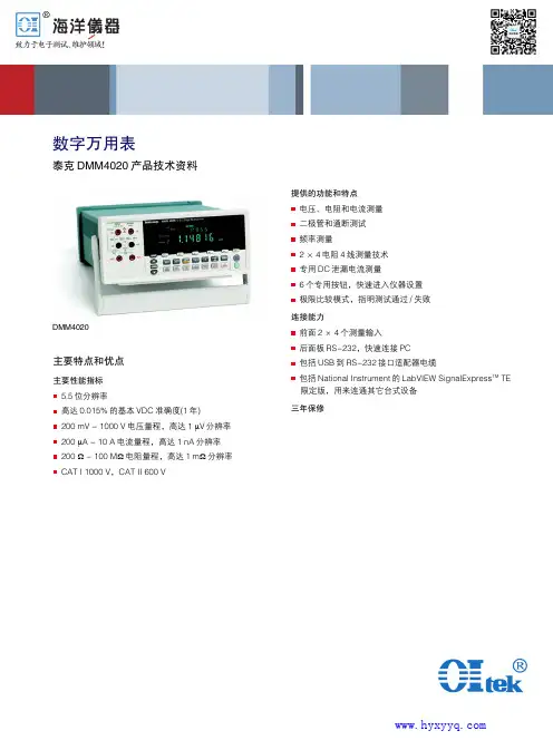
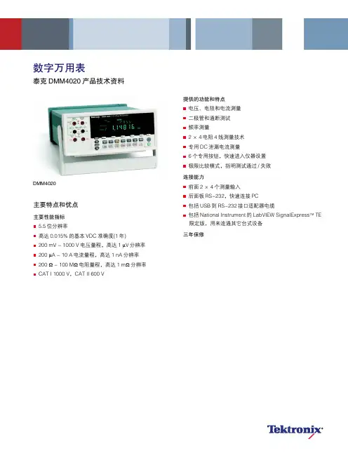
主要特点和优点主要性能指标 5.5位分辨率高达0.015%的基本VDC 准确度(1年) 200 mV - 1000 V 电压量程,高达1 µV 分辨率 200 µA - 10 A 电流量程,高达1 nA 分辨率 200 Ω - 100 M Ω电阻量程,高达1 m Ω分辨率 CAT I 1000 V,CAT II 600 V数字万用表泰克DMM4020产品技术资料提供的功能和特点 电压、电阻和电流测量 二极管和通断测试 频率测量2×4电阻4线测量技术 专用DC 泄漏电流测量6个专用按钮,快速进入仪器设置 极限比较模式,指明测试通过/失败连接能力前面2×4个测量输入 后面板RS-232,快速连接PC 包括USB 到RS-232接口适配器电缆包括National Instrument 的LabVIEW SignalExpress TM TE 限定版,用来连通其它台式设备三年保修DMM40202产品技术资料只需按一个按钮,即可轻松进行测量随着嵌入式系统中的电路日益完善,您必须测量大量不同的参数,验证设计。
泰克DMM4020 5.5位台式万用表在一台简便易用的仪器中提供了大量的功能。
它可以以高达0.015%的基本VDC准确度,执行电压、电阻和电流等典型的万用表测量,确保为设计提供所需的仪器性能。
您还可以使用DMM4020测量频率,执行通断测试和二极管测试。
您可以使用一台多功能仪器代替计数器、通断测试仪和传统DMM,节约工作台空间和成本。
测量毫微安培信号测量当前能耗效率高的设计中的待机电流,要求考察非常低的电流,其通常只有几微安或几纳安。
对这种测量,使用传统万用表会导致结果不准确,因为传统万用表一般采用分流电阻技术来测量电流。
DMM4020改进了测量低电流的方法。
通过使用电流到电压功放技术,DMM4020可以以1nA 的分辨率测量电流,给被测电流带来的负荷影响达到最小,其结果反映了设备在实际环境中的工作情况。
第四节微机自动准同期装置的维护Section four Maintenance of microcomputer automatic quasi-synchronization deviceSID-2SL-A型微机多功能同步表技术说明SID-2SL-A type microcomputer multi-functional synchronization meter technical description概述General本装置集同步表和同期闭锁继电器于一体,用于手动同期相位角指示,及手动同期和自动同期同期闭锁功能。
主要功能如下:This device integrates synchronization meter and synchronization blocking relay, used to manual synchronization phase angle indication and manual synchronization and automatic synchronization blocking functions. The major functions are as follows: 1.1 并列点两侧电压相位角指示,用模拟和数字两种方式显示。
1.2 该装置有多达12个同期闭锁继电器,每个同期闭锁继电器可单独整定闭锁角,在外部输入同频或差频并网类别开入量时,被选中的同期闭锁继电器将自动设置与并网性质相对应的同期闭锁角整定值。
1.3 同步表输入的TV二次电压可为相电压、线电压或220V电压。
如果两侧电压存在固有相角差,可通过对每个并列点的系统侧电压单独设置转角进行修正。
1.4 每个并列点可单独设置允许压差、允许频差。
当电压差或频率差超过允许值时,闭锁继电器自动闭锁合闸回路。
1.5 支持单侧无压合闸或双侧无压合闸。
在满足单侧无压合闸或双侧无压合闸条件时,闭锁继电器一直导通,而不需使用其他回路来解除该闭锁继电器。
Agilent U1240 Series Handheld Digital MultimetersHelping You Check and Fix More Installation and Maintenance BugsData SheetThe Agilent U1240 Series handheld digital multimeters enable you to check more with wider measurement ranges. They feature true RMS readings on their 10,000-count displays. The adjustable backlighting allows you to complete your jobs even in subdued lighting conditions, or to simply prolong battery life. Your maintenance tasks are greatly simplified due to the built-in switch counter, harmonic ratio, dual and differential temperature capabilities, with just a press of the button. The meters have a high safety rating with CAT III 1000 V and CAT IV 600 V protection and are certified to CE and CSA standards. On top of that, the U1240 Series comes with a certificate of calibration and test report – at no extra cost.The latest multimeters in this series, the U1241B and U1242B, now come in vivid orange cases, offering the capabilities and functions you need.Key featuresCheck more, fix more • 10,000-count display • 0.09% basic DCV accuracy • True RMS AC measurement • Basic functions — ACV, DCV, ACI, DCI, resistance, frequency, diode, continuity tests • Advanced functions — Capacitance, temperature, MINMAX recording Ease of use• Adjustable backlighting — two intensity levels • Manual data logging (U1242B only)• Built-in switch counter,harmonic ratio (U1242B only), dual/differential temperature capabilities (U1242B only)Built to last• Overmold body casing • CAT III 1000 V andCAT IV 600 V safety protection • Certified to CE and CSA standards • Operating temperature:–10 to 55 °CAmbient temperatureT1–T2 Differential Temperature (U1242B only)Functions and ranges at a glanceDC specificationsVoltage11000.0 mV0.1 mV–0.09% + 510.000 V0.001 V–0.09% + 2 100.00 V0.01 V–1000.0 V0.1 V–0.15% + 5Current 1000.0 µA0.1 µA< 0.06 V (50 Ω)0.1% + 3 10000 µA 1 µA< 0.55 V (50 Ω)0.1% + 3 100.00 mA0.01 mA< 0.18 V (0.5 Ω)0.2% + 3 440.0 mA20.1 mA< 0.8 V (0.5 Ω)0.5% + 3 10.000 A30.001 A< 0.4 V (0.01 Ω)0.6% + 5Resistance41000.0 Ω50.1 Ω0.5 mA0.3% + 3 10.000 kΩ50.001 kΩ50 µA100.00 kΩ0.01 kΩ 4.91 µA1000.0 kΩ0.1 kΩ447 nA10.000 MΩ0.001 MΩ112 nA0.8% + 3 100.00 MΩ60.01 MΩ112 nA 1.5% + 3Diode test7 1 V0.001 V approximately 0.5 mA0.3% + 21. Input impedance: 10 MΩ (nominal).2. Current can be measured up to 440 mA continuously. An additional 0.2% needs to be added to the specified accuracy if the signal measured is in therange of 440 mA to 1100 mA for 30 seconds maximum. After measuring a current of > 440 mA, leave the meter to cool down for twice the measur-ing time used before applying a low current measurement.3. Current can be measured up to 10 A continuously with a maximum operating temperature of 50 °C. An additional 0.3% needs to be added to thespecified accuracy if the signal measured is in the range of 10 A to 19.999 A for 15 seconds maximum. After measuring a current of > 10 A, leave the meter to cool down for 60 seconds before applying a low current measurement.4. The maximum open voltage is < 2.8 V. For instant continuity, the built-in buzzer sounds when resistance is < 10.0 Ω.5. The accuracy of 1 kΩ and 10 kΩ is specified after Null function, which is used to substrate the test lead resistance and the thermal effect.6. For the range of 100 MΩ, the R.H. is specified for < 60%. The temperature coefficient will be 0.15 times of specified accuracy as > 50 MΩ.7. Overload protection: 1000 V RMS for circuits < 0.3 A short circuit current. The built-in buzzer sounds when reading is approximately below 50 mV andaudible single tone for normal forward biased diode or semiconductor junction as 0.3 V ≤ Reading ≤ 0.8 V.AC specificationsAC voltage8, 12 True RMS 1000.0 mV0.1 mV–1% + 52% + 5–10.000 V0.001 V–1% + 52% + 5 100.00 V0.01 V–1000.0 V0.1 V––AC current9, 12 True RMS 1000.0 µA0.1 µA< 0.06 V (50 Ω)1% + 5 1.5% + 5–10000 µA 1 µA< 0.55 V (50 Ω)100.00 mA0.01 mA< 0.18 V (0.5 Ω)440.0 mA100.1 mA< 0.8 V (0.5 Ω)10.000 A110.001 A< 0.4 V (0.01 Ω)8. Input impedance: 10 MΩ (nominal) in parallel with < 100 pF, with overload protection of 1000 V RMS9. Crest factor ≤ 3. For non-sinusoidal waveforms with crest factor up to 3, add 2% reading + 2% full scale typical.10. Current can be measured from 50 mA to 440 mA continuously. An additional 0.2% needs to be added to the specified accuracy if the signalmeasured is in the range of 440 mA to 1100 mA for 30 seconds maximum. After measuring a current of > 440 mA, leave the meter to cool down for twice the measuring time used before application of low current measurement.11. Current can be measured from 0.5 A up to 10 A continuously with a maximum operating temperature of 50 °C. An additional 0.3% needs to be addedto the specified accuracy if the signal measured is in the range of 10 A to 19.999 A for 15 seconds maximum. After measuring a current of >10 A, leave the meter to cool down for 60 seconds before applying a low current measurement.12. AC voltage and AC current specifications are AC coupled. True RMS measurement is valid from 5 % of range to 100 % of range. Temperature specificationsThermocouple type Range Resolution Accuracy ± (% of reading + offset error)K (for U1241B and U1242B)–40 to 1000 ºC/–48 to 1832 ºF0.1 °C /0.1 °F1% + 1 ºC/1% + 1.8 °FJ (for U1242B only)–40 to 1000 ºC/–48 to 1832 ºF0.1 ºC/0.1 ºF1% + 1 ºC/1% + 1.8 °FCapacitance specificationsRange Resolution Accuracy ± (% of reading + counts of least significant digit) 1000.0 nF0.1 nF1.2% + 410.000 µF0.001 µF100.00 µF0.01 µF1000.0 µF0.1 µF2% + 410.000 mF0.001 mFHarmonic ratio specificationsRange Frequency Voltage0.0% to 99.9%40 to 500 Hz100 mVAC to 1000 VACSwitch counter definition3Low level Normally close Lo< 370 ohms Intermittent 4Close to open Number of switch count Low to high transition High level Normally open Hi> 430 ohms Intermittent 5Open to closeNumber of switch countHigh to low transition1. Detects intermittent Opens or Closes lasting for at least 250 μsec.2. Test current of 0.5 mA with maximum open circuit voltage of 2.8 V is used.3. Maximum count reading: 199.99 M (display “OL” when achieving 2 x 10⁸ and thereafter).4. Count only low to high transition for initial switch condition of Low.5.Count only high to low transition for initial switch condition of High.Frequency specifications RangeResolutionAccuracy Minimum input frequency100.00 Hz 0.01 Hz 0.03%+3 1 Hz1000.0 Hz 0.1 Hz 10.000 kHz 0.001 kHz 100.00 kHz 0.01 kHz 1000.0 kHz 10.1 kHz1. Effective frequency measurement of up to 200 kHz; refer to frequency sensitivity table below for details.Frequency sensitivity during voltage measurement1000.0 mV 0.3 V 0.6 V 10.000 V 0.5 V 1.8 V100.00 V 5 V 10 V (< 100 kHz)1000.0 V50 V100 V (< 100 kHz)Frequency sensitivity during current measurement1000.0 µA 100 µA 10000 µA 500 µA 100.00 mA 10 mA 440.00 mA 50 mA 10.000 A1 AMeasuring rateACV7DCV (V or mV)7Ω14Diode14Capacitance 4 (< 100 µF)DCA (μA, mA, A)7ACA (μA, mA, A)7Temperature7 (single)Frequency 1 (> 10 Hz)General SpecificationsDisplay Dual display (secondary display is intended for temperature function display only)consists of 4-digit liquid crystal display (LCD) with maximum reading of 11,000 counts.Automatic polarity indication.Power consumption0.22 VA maximumBattery type and life Four single standard 1.5 V AAA batteries (Alkaline or Zinc Chloride type); 300 hourstypicalOperating environment• Full accuracy at –10 to 55 °C; and to 80% RH for temperatures up to 30 °C, decreasinglinearly to 50% RH at 55 °C• 0 – 2000 meters per IEC 61010-1 2nd Edition CAT III, 1000 V / CAT IV, 600 V IEC61010-1 2nd EditionStorage compliance–20 to 70 °CSafety compliance• IEC 61010-1:2001 / EN61010-1:2001• Canada: CSA C22.2 No. 61010-1:2004Measurement category CAT III 1000 V / CAT IV 600 V Overvoltage Protection, Pollution Degree 2EMC compliance• CISPR 11:1990/EN55011:1990• Canada: ICES-001:2004• Australia/New Zealand: AS/NZS CISPR11:2004Common Mode Rejection Ratio (CMRR)> 90 dB at DC, 50/60 Hz ± 0.1% (1 kΩ unbalanced)Normal Mode Rejection Ration (NMRR)> 60 dB at 50/60 Hz ± 0.1%Crest factor< 3.0Temperature coefficient0.1 × (specified accuracy) / °C (from –10 to 18 °C or 28 to 55 °C)Shock and vibration Tested to IEC/EN 60068-2Dimensions (H x W x D)193.8 mm x 92.2 mm x 58.0 mmWeight• 450 g with batteries• 400 g without batteriesWarranty• Three years for main unit• Three months for standard shipped accessoriesOrdering Information• Four 1.5 V AAA alkaline batteries• Certificate of Calibration (CoC)• Test probe leads (4-mm tips)• Quick Start Guide• Free test data (Option UK6)Measuring accessories (non-temperature)U1161A Extended testlead kit Includes two test leads (red and black), two test probes, medium-sized alligator clips and 4-mm banana plugs.• Test leads: CAT III 1000 V, CAT IV 600 V, 15 A• Test probes: CAT lll 1000 V, CAT lV 600 V, 15 A• Medium-sized alligator clips: CAT III 1000 V, CAT IV 600 V, 15 A • 4-mm banana plugs: CAT II 600 V, 10 AU1162AAlligator clips • One pair of insulated alligator clips (red and black).Recommended for use with Agilent standard test leads.• Rated CAT III 1000 V, CAT IV 600 V, 15 AU1163ASMT grabbers • One pair of SMT grabbers (red and black). Recommended for use with Agilent standard test leads.• Rated CAT II 300 V, 3 AU1164A Fine-tip testprobes • One pair of fine-tip test probes (red and black). Recommended for use with Agilent standard test leads.• Rated CAT II 300 V, 3 AU1168A Standard testlead kit Includes two test leads (red and black), 19-mm and 4-mm test probes, alligator clips, fine-tip test probes, SMT grabbers and mini grabber (black).• Test leads: CAT III 1000 V, CAT IV 600 V, 15 A• Test probes (19-mm tip): CAT II 1000 V, 15 A• Test probes (4-mm tip): CAT III 1000 V, CAT IV 600 V, 15 A (highly recommended for CAT IV environment)• Alligator clips: CAT III 1000 V, CAT IV 600 V, 15 A• Fine-tip test probes: CAT II 300 V, 3 A• SMT grabber: CAT II 300 V, 3 A• Mini grabber: CAT II 300 V, 3 AU1169ATest probe leads Includes two test leads (red and black), and a pair each of 19-mm and 4-mm test probes.• Test leads: CAT III 1000 V, CAT IV 600 V, 15 A• Test probes (19-mm tip): CAT II 1000 V, 15 A• Test probes (4-mm tip): CAT III 1000 V, CAT IV 600 V, 15 A (highly recommended for CAT IV environment)U1583BAC current clamp • Dual range: 40 A and 400 A• Rated CAT III 600 V• BNC-to-banana-plug adapter provided for use with DMMsU1241B U1242BMagnetic hangingkitU1179A IR Connectivity Bracke Connect with U1177A IR-to-Bluetooth adapter or U1173A IR-USB cableOrdering Information/find/handhelddmmLAN eXtensions for Instruments puts the power of Ethernet and the Web inside your test systems. Agilent is a founding member of the LXI consortium.Agilent Channel Partners/find/channelpartners Get the best of both worlds: Agilent’s measurement expertise and product breadth, combined with channel partner convenience.For more information on AgilentTechnologies’ products, applications or services, please contact your local Agilent office. The complete list is available at:/find/contactus Americas Canada (877) 894 4414 Brazil (11) 4197 3600Mexico 01800 5064 800 United States (800) 829 4444Asia Pacifi c Australia 1 800 629 485China 800 810 0189Hong Kong 800 938 693India 1 800 112 929Japan 0120 (421) 345Korea 080 769 0800Malaysia 1 800 888 848Singapore 180****8100Taiwan 0800 047 866Other AP Countries (65) 375 8100Europe & Middle East Belgium 32 (0) 2 404 93 40 Denmark 45 45 80 12 15Finland 358 (0) 10 855 2100France 0825 010 700**0.125 €/minute Germany 49 (0) 7031 464 6333 Ireland 1890 924 204Israel 972-3-9288-504/544Italy 39 02 92 60 8484Netherlands 31 (0) 20 547 2111Spain 34 (91) 631 3300Sweden 0200-88 22 55United Kingdom 44 (0) 118 927 6201For other unlisted countries: /find/contactus(BP-3-1-13)Product specifications and descriptions in this document subject to change without notice.© Agilent Technologies, Inc. 2013Published in USA, July 11, 20135989-7040EN/qualityAdvancedTCA ® Extensions forInstrumentation and Test (AXIe) is an open standard that extends theAdvancedTCA for general purpose and semiconductor test. Agilent is a founding member of the AXIe consortium.PCI eXtensions for Instrumentation (PXI) modular instrumentation delivers a rugged, PC-based high-performance measurement and automation system.Quality Management SystemQuality Management Sys ISO 9001:2008DEKRA Certified /find/myagilentA personalized view into the information most relevant to you.myAgilent my Agilent/find/AdvantageServices Accurate measurements throughout the life of your instruments.Agilent Advantage ServicesThree-Year Warranty/find/ThreeYearWarranty Agilent’s combination of product reliability and three-year warranty coverage is another way we help you achieve your business goals: increased confidence in uptime, reduced cost of ownership and greater convenience.。
Agilent U1230 SeriesHandheld Digital Multimeters (DMMs)Data SheetWhether it is dark, noisy or evendangerous, the U1230 Series handheld digital multimeters keep you equipped with features that anticipate worst-case scenarios. The ergonomic shaped handheld allows you to single-handedly illuminate the test area with a built-in flashlight while selecting measurement functions using the rotary dial. Vsense performs non-contact voltage detection while continuity detection is made easy with the audible beeper alert and flashing backlight display. With the U1230 Series, you work better in the conditions you are in.• Built-in LED flashlight to illuminate test area • Flashing backlight as additional visual alert during continuity tests in noisy environments • Vsense to perform non-contact voltage detection • Data logging capability (stores up to 10 readings)• IR-to-USB connectivity to transfer data to PC for recordErgonomically shaped with a built-in flashlightBuilt for handheld users working in a poorly lit environment, the U1230 Series allows you to single-handedly illuminate your test area while making measurements with its easily activated built-in flashlight. Its ergonomicshape fits your hand, while the easily accessible rotary dial allows selection of measurement functions.Flashing backlight and beeping alert for continuity detectionThe U1230 Series is built for con-tinuity detection in dark and noisy environments. Its audible beep and flashing backlight display provides increased visual and audio alert to indicate continuity.Non-contact voltage detection with VsenseThe Vsense, a unique feature found in the U1233A model performs non-contact voltage detection. It delivers more safety while making measurements in dangerous working environments by avoiding any contact with hot or live wires. Upon detection of voltage, it produces a unique combination of beeping alert and blinking LED light to make measure-ments more efficiently – especially in a dark or noisy environment.FeaturesRetool your expectations with the new Agilent U1230 Series Handheld DMMs- the first to combine a built-in LED flashlight, both audible and visual alerts, and non-contact AC voltage detection in one handheld.Take a Closer LookLow input impedance to eliminate ghost voltagemeasurement Anti-slip rotary dial for easy measurementfunction selectionFlashing light and audible beep during presence of voltage 1Bar graph indication and frequency measurement pathVsense performs non-contact voltage detection 1Ease viewing with display backlight or built-in flashlightFigure 1. U1230 Series front viewFreezes and stores currentmeasurement value Allows flexibility to changemeasurement rangeFigure 2. The built-in flashlight as illustratedNotes:1. Only applicable for the U1233A modelDC specificationsNotes for DC voltage specifications:1. The accuracy of the 600 mV range is specified after the Null function is used to subtract the thermal effect (by shorting the test leads).2. For VZ(low input impedance) measurements, auto-ranging is disabled and the multimeter’s range is set to 600 V in the manual ranging mode.LOWNotes for resistance specifications:1. Overload protection: 600 Vrms for short circuits with < 0.3 A current.2. Maximum open voltage is < +3 V.3. Built-in buzzer beeps when the resistance measured is less than 23 Ω ± 10 Ω. The multimeter can capture intermittent measurements longer than 1 ms.4. The accuracy of the 600 Ω to 6 kΩ range is specified after the Null function is used to subtract the test lead resistance and thermal effect (by shortingthe test leads).5. For the ranges of 6 MΩ and 60 MΩ, the RH is specified for < 60%.Notes for diode specifications:1. Overload protection: 600 Vrms for short circuits with < 0.3 A current.2. Built-in buzzer beeps continuously when the voltage measured is less than 50 mV and beeps once for forward-biased diode or semiconductorjunctions measured between 0.3 V and 0.8 V (0.3 V ≤ reading ≤ 0.8 V).3. Open voltage for diode: < +3 V DC.4. The maximum display for diode measurements is 2100 counts.Notes for DC current specifications:1. Overload protection for 60 μA to 600 μA range: 600 Vrms for short circuits with < 0.3 A current.2. Overload protection for 6 A to 10 A range: 11 A/1000 V; 10 × 38 mm fast-acting fuse.3. Specification for 10 A range: 10 A continuous. Add 0.3% to the specified accuracy when measuring signals > 10 A to 20 A for 30 seconds maximum. Aftermeasuring currents > 10 A, cool down the multimeter for twice the duration of the measured time before proceeding with low current measurements.4. Only applicable for the U1232A/U1233A model5. DC current range of 0.6 μA to 1 μA is not measureable on the U1232A and U1233A models.AC specificationsVoltage600 mV0.1 mV 1.0% + 3 2.0% + 3NA6 V0.001 V 1.0% + 3 2.0% + 3NA60 V0.01 V 1.0% + 3 2.0% + 3NA600 V0.1 V 1.0% + 3 2.0% + 3NA)30.1 V 2.0% + 3 4.0% + 3NA600 (VZLOWCurrent160 μA20.01 μA 1.5% + 3NA< 2.5 V/1 kΩ600 μA20.1 μA 1.5% + 3NA< 2.5 V/1 kΩ6 A3,50.001 A 1.5% + 3NA< 0.2 V/0.005 Ω10 A3, 40.01 A 1.5% + 3NA< 0.4 V/0.005 ΩNotes for true rms ac voltage specifications:1. Overload protection: 600 Vrms. For millivolt measurements, 600 Vrms for short circuits with < 0.3 A current.2. Input impedance: 10 MΩ (nominal) in parallel with < 100 pF.3. VZinput impedance: 3 kΩ (nominal).LOWNotes for ac current specifications:1. AC current measurement not available for U1231A model.2. Overload protection for 60 μA to 600 μA range: 600 Vrms for short circuits with < 0.3 A current.3. Overload protection for 6 A to 10 A range: 11 A/1000 V; 10 × 38 mm fast-acting fuse.4. Specification for 10 A range: 10 A continuous. Add 0.3% to the specified accuracy when measuring signals > 10 A to 20 A for 30 seconds maximum.After measuring currents > 10 A, cool down the multimeter for twice the duration of the measured time before proceeding with low current measurements.5. AC current range of 0.6 μA to 300 μA is not measureable on the U1232A and U1233A modelsCapacitance specifications1000 nF 1 nF 1.9% + 2 4 times/second10 μF0.01 μF 1.9% + 2 4 times/second100 μF0.1 μF 1.9% + 2 4 times/second1000 μF 1 μF 1.9% + 2 1 time/second10 mF0.01 mF 1.9% + 20.1 time/secondNotes :1. Overload protection: 600 Vrms for short circuits with < 0.3 A current.2. The accuracy of for all ranges is specified based on a film capacitor or better, and after the Null function is used to subtract the test lead resistanceand thermal effect (by shorting the test leads).3. The maximum display is 1200 counts.Temperature specificationsK –40 °C to 1372 °C 0.1 °C 1% + 1 °C –40 °F to 2502 °F0.1 °F1% + 1.8 °FNotes:1. The specification above is specified after 60 minutes of warm up time. If the unit is exposed during storage in high humidity (condensing) environ-ment, 120 minutes of operating time is required instead.2. The accuracy does not include the tolerance of the thermocouple probe.3. Do not allow the temperature sensor to contact a surface that is energized above 30 Vrms or 60 V DC. Such voltages poses a shock hazard.4. Ensure that the ambient temperature is stable within ±1 ºC and that the Null function is used to reduce the test lead’s thermal effect and temperature offset. Before using Null function, set the multimeter to measure temperature without ambient compensation (°C) and keep the thermocouple probe as close as possible to the multimeter (avoid contact with any surface that has a different temperature from the ambient temperature).5. When measuring temperature with respect to any temperature calibrator, try to set both the calibrator and multimeter with an external reference (without internal ambient compensation). If both the calibrator and multimeter are set with internal reference (with internal ambient compensation), some deviations may show between the readings of the calibrator and multimeter, This difference is caused from the calibrator and multimeters’s ambient compensation. The deviation can be reduced by keeping the multimeter close to the output terminal of calibrator.6. The temperature calculation is specified according to the safety standards of EN/IEC-60548-1and NIST175.7. The approximate ambient temperature (cold-junction compensation) is shown on the display when you have an open thermocouple. The open thermocouple message may be due to broken (open) probe or because no probe is installed into the input jacks of the multimeter.8. For temperature measurement on U1233A, the type-K thermocouple probe and adapter such as the U1186A (purchase separately) is required.9. For auxillary temperature measurement on U1231A & U1232A, a temperature module such as the U1586B (purchase separately) is required.Frequency specifications99.99 Hz 0.01 Hz 0.1% + 2 5 Hz999.9 Hz 0.1 Hz 0.1% + 29.999 kHz 1 Hz 0.1% + 299.99 kHz10 Hz0.1% + 2Notes:1. Overload protection: 600 V; input signal is < 20,000,000 V × Hz (product of voltage and frequency).Frequency sensitivity specifications600 mV in Scale mode50 mV50 mV50 mV 600 mV120 mV120 mV120 mV 6 V0.6 V0.6 V0.6 V 60 V 5.0 V 5.0 V 5.0 V 600 V50 V50 V50 VNotes:1. Maximum input for specified accuracy, refer to “AC specifications” on page 106 of the User Guide.60 μA30 μA30 μA600 μA30 μA30 μA6 A0.5 A0.5 A10 A0.5 A0.5 ANotes:1. Maximum input for specified accuracy, refer to “AC specifications” on page 106 of the User Guide.Scale transfer (mV)DC 600 mV0.1 mV0.5% + 22AC 600 mV0.1 mV 1.0 % + 3 @ 45 Hz to 500 Hz2.0 % + 3 @ 500 Hz to 1 kHzNotes:1. Overload protection: 600 Vrms for short circuits with < 0.3 A current.2. The accuracy of the DC 600 mV range is specified after the Null function is used to subtract the thermal effect (by shorting the test leads).3. Input impedance: 10 MΩ (typical).Display update rate (approximate)AC V (V or mV)55DC V (V or mV)55)11AC V/DC V (VZLOWScale transfer (mV)55Ω55Diode55 Capacitance 4 (< 100 μF) 4 (< 100 μF) DC A (μA, mA, or A)NA5AC A (μA, mA, or A)NA5 Frequency 1 (> 10 Hz) 1 (> 10 Hz)Power supplyBattery type • 4 × 1.5 V AAA Alkaline battery (ANSI/NEDA 24A or IEC LR03), or • 4 × 1.5 V AAA Zinc Chloride battery (ANSI/NEDA 24D or IEC R03)Battery life• 500 hours typical (based on new Alkaline batteries) with backlight and flashlight disabled Low battery indication• Low battery indicator will flash when the battery voltage drops below approximately 4.4 VPower consumption 450 mVA maximum (with backlight and flashlight enabled)Fuse 10 × 38 mm 11 A/1000 V fast-acting fuseDisplay Liquid crystal display (LCD) (with maximum reading of 6600 counts)FlashlightCool white LED (5500 K typical); luminous intensity from 2240 mcd to 5600 mcd Operating environment• Operating temperature from –10 °C to 55 °C, 0% to 80% RH• Full accuracy up to 80% RH for temperatures up to 30 °C, decreasing linearly to 50% RH at 55 °C • Altitude up to 2000 meters •Pollution degree IIStorage compliance –40 °C to 60 °C, 0% to 80% RH without batteriesSafety compliance EN/IEC 61010-1:2001, ANSI/UL 61010-1:2004, and CAN/CSA-C22.2 No. 61010-1-04Measurement category CAT III 600 VElectromagnetic compatibility (EMC)Commercial limits compliance with EN61326-1Temperature coefficient 0.1 × (specified accuracy) / °C (from –10 °C to 18 °C, or 28 °C to 55 °C)Common Mode Rejection Ratio (CMRR)> 100 dB at DC, 50/60 Hz (1 kΩ unbalanced)Normal Model Rejection Ration (NMRR)> 60 dB at 50/60 Hz Dimensions (H x W x D)169 mm × 86 mm × 52 mmWeight U1232A and U1233A: 371 grams (with batteries and holster)U1231A: 365 grams (with batteries and holster)Warranty • Three years for product 1• Three months for product’s accessories Calibration cycleOne yearNotes:1. Please take note that for the product, the warranty does not cover: • Damage from contamination• Normal wear and tear of mechanical components • Manuals, fuses, and batteriesSpecification assumptions• Accuracy is given as ±(% of reading + counts of least significant digit) at 23 °C ± 5 °C, with relative humidity less than 80% RH.• AC V and AC A specifications are AC coupled, true RMS and are valid from 5% of range to 100% of range.• The crest factor may be up to 3.0 at full- scale (4000 counts)• For non- sinusoidal waveforms, add (2% reading + 2% full scale) typical.• After VZ LOW (low input impedance) voltage measurements, wait at least 20 minutes for thermal impact to cool before proceeding with any other measurement.Ordering InformationStandard U1231A, U1232A and U1233A include:• Quick Start Guide• Certificate of Calibration (CoC)• U1167A 4 mm Tips probes test leads• 4 x 1.5 V batteriesU1174A Soft carrying caseU1168A Standard test lead kitU1173A IR-to-USB cableU1171A Magnetic hanging kit/find/U1230DMMAgilent Email Updates/find/emailupdates Get the latest information on the products and applications you select.LAN eXtensions for Instruments puts the power of Ethernet and the Web inside your test systems. Agilent is a founding member of the LXI consortium.Agilent Channel Partnersw w w /find/channelpartners Get the best of both worlds: Agilent’s measurement expertise and product breadth, combined with channel partner convenience.For more information on AgilentTechnologies’ products, applications or services, please contact your local Agilent office. The complete list is available at:/find/contactus Americas Canada (877) 894 4414 Brazil (11) 4197 3600Mexico 01800 5064 800 United States (800) 829 4444Asia Pacific Australia 1 800 629 485China 800 810 0189Hong Kong 800 938 693India 1 800 112 929Japan 0120 (421) 345Korea 080 769 0800Malaysia 1 800 888 848Singapore 180****8100Taiwan 0800 047 866Other AP Countries (65) 375 8100 Europe & Middle East Belgium 32 (0) 2 404 93 40 Denmark 45 45 80 12 15Finland 358 (0) 10 855 2100France 0825 010 700**0.125 €/minuteGermany 49 (0) 7031 464 6333 Ireland 1890 924 204Israel 972-3-9288-504/544Italy39 02 92 60 8484Netherlands 31 (0) 20 547 2111Spain 34 (91) 631 3300Sweden0200-88 22 55United Kingdom 44 (0) 118 927 6201For other unlisted countries:/find/contactusRevised: January 6, 2012Product specifications and descriptions in this document subject to change without notice.© Agilent Technologies, Inc. 2012Published in USA, September 20, 20125990-7550ENAgilent Advantage Services is committed to your success throughout your equip-ment’s lifetime. To keep you competitive, we continually invest in tools andprocesses that speed up calibration and repair and reduce your cost of ownership. You can also use Infoline Web Services to manage equipment and services more effectively. By sharing our measurement and service expertise, we help you create the products that change our world./quality/find/advantageservicesAdvancedTCA ® Extensions for Instrumentation and Test (AXIe) is an open standard that extends the AdvancedTCA for general purpose and semiconductor test. Agilent is a founding member of the AXIe consortium.PCI eXtensions for Instrumentation (PXI) modular instrumentation delivers a rugged, PC-based high-performance measurement and automation system.Quality Management SystemQuality Management Sys ISO 9001:2008DEKRA CertifiedAgilent U1177A Infrared (IR)-to-Bluetooth adapter offers wireless remote connectivity solution via Bluetooth connection simply by attaching the adapter to the IR port of an Agilent handheld digital multimeter. The wireless remote connectivity is set up when an Agilent handheld digital multimeter is connected to U1177A and an Android device (tablet or smart phone) with the installed software. Every U1177A also has a unique Media Access Control (MAC)address. User can quickly and easily scan for the right U1177A using their Android device and pair up with the U1177A.Features• Enables Bluetooth connec-tion to Agilent handhelddigital multimeters •Easy to install by attaching to Infrared (IR) port located at the back of Agilent hand-held digital multimeters •Compatible with Agilent U1230 series, U1240 series, U1250 series and U1270 series handheld digital multimeters•Operated by two 1.5 V AAA batteriesBluetooth and the Bluetooth logos are trademarks owned by Bluetooth SIG, Inc., U.S.A. and licensed to Agilent Technologies, Inc.Figure 2. Agilent wireless remote connectivity solutionFigure 1. Award winning U1177A Infrared (IR)-to-Bluetooth adapter is being recognized as an innovative solution in Test & Measurement industryTake a closer lookLow battery indication:Red LED flashingBluetooth disconnected:Green LED flashingBluetooth connected:Green solid LEDBluetooth power off:LED offON/OFF/Setupslide switchFigure 3. The U1177A as illustratedAgilent Mobile Meter is a free Android application software that allows an Android device to connect, control and perform up to 3 multimeter measure-ments. Without the need to be physically present at various points, users can now extend their reach to two or three places. This solution allows you to make measurements from a safe distance, eliminates the need to walk back-and-forth between measure target and control points, and monitors multiple measure-ments simultaneously. Achieve higher work productivity when you use theU1177A with your Agilent handheld digital multimeters.Monitor up to three multimeter measurements at the same timewith Agilent Mobile MeterFigure 5. Up to three multimeters measurements with the Agilent Mobile MeterFigure 6. Make measurements with the Agilent Mobile Meter via an Android smart phoneData logging is an important function for industrial users to capture datastreams or plotting trending graphs. These data and graphs are used for analysis to identify intermittent behavior or detect drifts. Agilent Mobile Logger is the free Android application software that logs data and provides trending graphs from Agilent handheld digital multimeters. Agilent Mobile Logger offers an array of extended functions such as sending e-mail or Short Message Service (SMS) automatically, and pan and zoom function via the Android device’s touch screen. Alternatively, data logging and monitoring activities can also be performed at the comfort of one’s Personal Computer (PC) via a downloadable Agilent GUI data logger software.Perform data logging with up to three multimeters – wirelessly and simultaneously!Notes:1. Agilent Mobile Meter and Agilent Mobile Logger can be downloaded from /find/hh-Android or from Android Market (https:///)2. Agilent GUI Data Logger Software can be /find/hh-loggerFigure 4. Data logging with AgilentMobile Logger software.Radio specification• Frequency: 2402 MHz ~ 2480 MHz• Antenna Power: 1 mW or less• Number of Channels: 79• Modulation: GFSK / PSKOperating environment Operating temperature from –20 to 55 °CStorage environment Storage temperature from –40 to 70 °CRelative humidity (R.H.)Relative humidity up to 95% at 40 °C (non-condensing) Power consumption Maximum 130 mVA for two 1.5 V AAA batteries Battery life30 hours typical (based on continuous data transfer)Battery type Alkaline 24 A (ANSI/NEDA) and LR03 (IEC), or Zinc Chloride 24 D (ANSI/NEDA) and R03 (IEC)Dimension (W x H x L)39.0 × 71.0 × 37.0 mm Weight60 g with batteries Warranty Three monthsBluetooth "Bluetooth" Version 2.1 + EDR compliant, SPP profile, Class 2 device (with 10 metres connection range)Safety The U1177A complies with the requirements of the following safety and regulationstandards:• FCC Part15C (Certification) (15.209, 15.247) FCC ID: ZKMAGILENT-U1177A• FCC Part15B (DoC) (15.109)• RSS–210 Issue 8:2010 IC: 6310A–U1177A• ICES–003 Issue 4:2004• EN 300 328 V1.7.1:2008• EN 301 489–1V1.8.1:2008/–17 V2.11:2009• EN 55022:2006+A1:2007/EN55024:1998+A1:2001+A2:2003• EN 50371:2002• EN 60950–1:2006/A11:2009/A1:2010• Complies with IDA Standards (DB 102425)• India Equipment Type Approval (ETA) Certificate No: 1424/2011/WRLO• COFETEL Certificate No: RCPAGU111-1066, registered under Agilent TechnologiesMexico S de RL de CV"This telecommunication equipment conforms NTC technical requirement" SpecificationsStandard shipped items:• Two 1.5 V AAA batteries• Operating instructions/find/U1177ALAN eXtensions for Instruments puts the power of Ethernet and the Web inside your test systems. Agilent is a founding member of the LXI consortium.Agilent Channel Partners/find/channelpartners Get the best of both worlds: Agilent’s measurement expertise and product breadth, combined with channel partner convenience.For more information on AgilentTechnologies’ products, applications or services, please contact your local Agilent office. The complete list is available at:/find/contactus Americas Canada (877) 894 4414 Brazil (11) 4197 3600Mexico 01800 5064 800 United States (800) 829 4444Asia Pacifi c Australia 1 800 629 485China 800 810 0189Hong Kong 800 938 693India 1 800 112 929Japan 0120 (421) 345Korea 080 769 0800Malaysia 1 800 888 848Singapore 180****8100Taiwan 0800 047 866Other AP Countries (65) 375 8100Europe & Middle East Belgium 32 (0) 2 404 93 40 Denmark 45 45 80 12 15Finland 358 (0) 10 855 2100France 0825 010 700**0.125 €/minute Germany 49 (0) 7031 464 6333 Ireland 1890 924 204Israel 972-3-9288-504/544Italy 39 02 92 60 8484Netherlands 31 (0) 20 547 2111Spain 34 (91) 631 3300Sweden 0200-88 22 55United Kingdom 44 (0) 118 927 6201For other unlisted countries: /find/contactus(BP-3-1-13)Product specifications and descriptions in this document subject to change without notice.© Agilent Technologies, Inc. 2013Published in USA, March 13, 20135990-9531EN/qualityAdvancedTCA ® Extensions forInstrumentation and Test (AXIe) is an open standard that extends theAdvancedTCA for general purpose and semiconductor test. Agilent is a founding member of the AXIe consortium.PCI eXtensions for Instrumentation (PXI) modular instrumentation delivers a rugged, PC-based high-performance measurement and automation system.Quality Management SystemQuality Management Sys ISO 9001:2008DEKRA Certified /find/myagilentA personalized view into the information most relevant to you.myAgilent my Agilent/find/AdvantageServices Accurate measurements throughout the life of your instruments.Agilent Advantage ServicesThree-Year Warranty/find/ThreeYearWarranty Agilent’s combination of product reliability and three-year warranty coverage is another way we help you achieve your business goals: increased confidence in uptime, reduced cost of ownership and greater convenience.。
技术资料Keysight U1240 系列手持式数字万用表主要特性更宽的检查范围,更好的修理能力–10,000 计数显示–0.09% 基本直流电压精度–真有效值交流测量–基本功能——ACV、DCV、ACI、DCI、电阻、频率、二极管、导通测试–先进测量功能——电容、温度、最大最小记录易于使用–可调背光——两种亮度–手动数据记录(仅限 U1242B )–内置开关计数器、谐波比(仅限 U1242B)、双温/温差测量功能(仅限 U1242B)坚固耐用–铸模机壳–CAT III 1000 V 和 CAT IV 600 V 安全防护–遵从CE 和CSA 标准–工作温度:–10 至55 °C Keysight U1240 系列手持式数字多用表使您能够在更宽的测量范围检查更多的参数。
以10,000 计数显示真有效值是它的一项突出优点。
可调背光灯帮助您在较弱光效条件下完成测量任务,并且不会影响电池寿命。
只需按下按钮,您就能利用仪表的内置开关计数器、谐波比、双温和温差测量功能简化设备维护工作。
该系列仪表符合CAT III 1000 V 和CAT IV 600 V 安全指标,并已通过CE 和CSA 标准认证,因此具有很高的操作安全性。
更可贵的是,U1240 系列还附带校准证书和测试报告,并且没有额外的费用。
U1241B 和U1242B 是U1240 系列最新型号,它们使用了亮橙色的包装,为您提供所需要的功能和特性。
细察仪器环境温度T1–T2温差(仅限U1242B)直流技术指标1000.0 mV0.1 mV–0.09% + 510.000 V0.001 V–0.09% + 2100.00 V0.01 V–1000.0 V0.1 V–0.15% + 5电流1000.0 μA0.1 μA< 0.06 V (50 Ω)0.1% + 310000 μA 1 μA< 0.55 V (50 Ω)0.1% + 3100.00 mA0.01 mA< 0.18 V (0.5 Ω)0.2% + 3440.0 mA20.1 mA< 0.8 V (0.5 Ω)0.5% + 310.000 A30.001 A< 0.4 V (0.01 Ω)0.6% + 5电阻41000.0 Ω50.1 Ω0.5 mA0.3% + 310.000 kΩ50.001 kΩ50 μA100.00 kΩ0.01 kΩ 4.91 μA1000.0 kΩ0.1 kΩ447 nA10.000 MΩ0.001 MΩ112 nA0.8% + 3100.00 MΩ60.01 MΩ112 nA 1.5% + 3二极管测试7 1 V0.001 V近似0.5 mA0.3% + 21. 输入阻抗:10 MΩ(标称值)。
2. 可连续测量高达440 mA 的电流。
如果测得的信号在440 mA 至1100 mA 范围内保持最多30 秒,那么指定精度上要增加0.2% 的附加误差。
在测量了大于440 mA 的电流后,在进行低电流测量前需有两倍测量时间的冷却时间。
3. 在最大工作温度50 °C 时,可连续测量高达10A 的电流。
如果测得的信号在10A 至19.999 A 范围内保持最多15 秒,那么指定精度上要增加0.3% 的附加误差。
在测量了大于10 A 的电流后,在进行低电流测量前需有60 秒的冷却时间。
4. 最大开路电压< 2.8 V。
在即时导通测量中,当电阻< 10.0 Ω时,内置蜂鸣器将会报警。
5. 使用Null 功能后,精度范围规定为1 kΩ至10 kΩ,以降低测试引线电阻和热效应。
6. 规定100 MΩ量程的相对湿度小于60%。
大于50 MΩ时,温度系数为规定精度的0.15 倍。
7. 过载保护:< 0.3 A 短路电流的电路为1000 V RMS。
在低于50 mV,以及正向偏置二极管或半导体结的读数在0.3 V 至0.8 V 之间时,内部蜂鸣器将会报警。
8. 输入阻抗:10 M Ω(标称值)并联 < 100 pF 电容,带 1000 V RMS 过载保护。
9. 波峰因数 ≤ 3。
对于波峰因素为 3 的非正弦波形,增加(读数的 2% + 全量程的 2%)的附加误差(典型值)。
10. 可连续测量 50 mA 至 440 mA 的电流。
如果测得的信号在 440 mA 至 1100 mA 范围内保持最多 30 秒,那么指定精度上要增加 0.2% 的附加误差。
在测量了大于 440 mA 的电流后,在进行低电流测量前需有两倍测量时间的冷却时间。
11. 在最大工作温度 50 °C 时,可连续测量 0.5 A 至 10A 的电流。
如果测得的信号在 10A 至 19.999 A 范围内保持最多 15 秒,那么指定精度上要增加 0.3% 的附加误差。
在测量了大于 10 A 的电流后,在进行低电流测量前需有 60 秒的冷却时间。
12. 交流电压和交流电流技术指标为交流耦合,5% 至 100% 量程内的真有效值测量。
交流技术指标温度技术指标交流电压8, 12真有效值1% + 510.000 V 0.001 V –1% + 52% + 5100.00 V 0.01 V –1000.0 V 0.1 V ––交流电流9, 12真有效值1000.0 μA 0.1 μA < 0.06 V (50 Ω)1% + 5 1.5% + 5–10000 μA 1 μA < 0.55 V (50 Ω)100.00 mA 0.01 mA < 0.18 V (0.5 Ω)440.0 mA 100.1 mA < 0.8 V (0.5 Ω)10.000 A 110.001 A< 0.4 V (0.01 Ω)°C °F °C °F °C °F J (仅限 U1242B )–40 至 1000 °C /–48 至 1832 °F0.1 °C /0.1 °F1% + 1 °C /1% + 1.8 °F1.2% + 410.000 μF 0.001 μF 100.00 μF 0.01 μF 1000.0 μF 0.1 μF 2% + 410.000 mF0.001 mF0.0% 至 99.9%40 至 500 Hz100 mVAC 至 1000 VAC1. 探测瞬间开闭时间至少为 250 μs 。
2. 测试电流为 0.5 mA ,使用的最大开路电压为 2.8 V 。
3. 最大计数读数:199.99 M (当达到 2 x 10⁸ 或之后显示“OL ”)。
4. 当初始开关条件为低时,仅记录低至高的跳变数。
5. 当初始开关条件为高时,仅记录高至低的跳变数开关计数器定义电压测量时的频率灵敏度Ω瞬间动作5开至闭开关计数高至低跳变0.03%+3 1 Hz1000.0 Hz 0.1 Hz 10.000 kHz 0.001 kHz 100.00 kHz 0.01 kHz 1000.0 kHz10.1 kHz1. 有效频率测量达 200 kHz ;详情参见下面的频率灵敏度表。
10.000 V 0.5 V 1.8 V 100.00 V 5 V 10 V (< 100 kHz)1000.0 V50 V 100 V (< 100 kHz)μμ10000 μA 500 μA 100.00 mA 10 mA 440.00 mA 50 mA 10.000 A1 A开关计数器定义DCV (V 或mV)7Ω14二极管14电容 4 (< 100 μF) DCA (μA, mA, A)7ACA (μA, mA, A)7温度7(单一温度)频率 1 (> 10 Hz)通用技术指标U1241B U1242B– 校准证书(CoC)– 测试探头引线(4 mm 探针)– 快速入门指南– 免费提供测试数据(选件UK6)线套件和4 mm 香蕉插头。
–测试引线:CAT III 1000 V, CAT IV 600 V, 15 A–测试探头:CAT lll 1000 V, CAT lV 600 V, 15 A–中型鳄口形夹具:CAT III 1000 V, CAT IV 600 V, 15 A– 4 mm 香蕉插头:CAT II 600 V, 10 AU1162A 鳄口形夹具–一对(红色和黑色)绝缘鳄口形夹具,建议与是德科技标准测试引线配合使用。
–符合 CAT III 1000 V、CAT IV 600 V,15 A 标准U1163A SMT 抓取器–一对(红色和黑色)SMT 抓取器,建议与是德科技标准测试引线配合使用。
–符合 CAT II 300 V,3 A 标准U1164A 尖针测试探头•一对(红色和黑色)尖针测试探头,建议与是德科技标准测试引线配合使用。
•符合 CAT II 300 V,3 A 标准U1168A 标准测试引线套件包括一对测试引线(红色和黑色)、19 mm 和4 mm 测试探头,鳄口形夹具、尖针测试探头、SMT 抓取器和微型抓取器(黑色)。
–测试引线:CAT III 1000 V, CAT IV 600 V, 15 A–测试探头(19 mm 探针):CAT II 1000 V, 15 A–测试探头(4 mm 探针):CAT III 1000 V、CAT IV 600 V,15 A(强烈推荐用于 CAT IV 环境)–鳄口形夹具:CAT III 1000 V, CAT IV 600 V, 15 A–尖针测试探头:CAT II 300 V, 3 A–SMT 抓取器:CAT II 300 V, 3 A–微型抓取器:CAT II 300 V, 3 AU1169A 测试探头引线包括一对(红色和黑色)测试引线、一对具有19 mm 探针的测试探头和一对具有4 mm 探针的测试探头。
–测试引线:CAT III 1000 V, CAT IV 600 V, 15 A–测试探头(19 mm 探针):CAT II 1000 V, 15 A–测试探头(4 mm 探针):CAT III 1000 V、CAT IV 600 V,15 A(强烈推荐用于 CAT IV 环境)U1583B 交流电流钳– 双量程:40 A 和400 A– 符合 CAT III 600 V 标准– 提供用于数字万用表的 BNC 至香蕉插头适配器引线套件,J 型和 K 型–J/K 型热电偶适配器–J 型热电偶焊珠:–20 °C 至 200 °C –K 型热电偶焊珠:–20 °C 至 200 °C U1181A 浸入式温度探头–适用于油和其他液体的 K 型热电偶–测量范围:–50 °C 至 700 °C–包括连接至数字万用表的 U1184A 适配器U1182A 工业表面温度探头–适用于平面的 K 型热电偶 –测量范围:–50 °C 至 400 °C–包括连接至数字万用表的 U1184A 适配器U1183A 空气温度探头–适用于空气和非腐蚀性燃气的 K 型热电偶–测量范围:–50 °C 至 800 °C–包括连接至数字万用表的 U1184A 适配器U1184A 温度探头适配器–适用于数字万用表的微型连接器与香蕉插头适配器U1185A 热电偶(J 型)和温度探头适配器 –J/K 型热电偶适配器–J 型热电偶焊珠:–20 °C 至 200 °CU1186A 热电偶(K 型)和温度探头适配器 –J/K 型热电偶适配器–J 型热电偶焊珠:–20 °C 至 200 °CU1179A IR 连通性支架连接 U1177A 红外至蓝牙适配器或 U1173A 红外至 USB 电缆09 | Keysight | U1240 系列手持式数字万用表-技术资料如欲获得是德科技的产品、应用和服务信息, 请与是德科技联系。