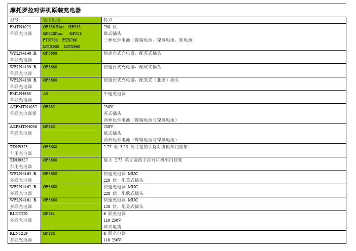
原装正品立锜原装RT9293
- 格式:pdf
- 大小:1.10 MB
- 文档页数:13

如需产品安装、维护或支持信息,请参考文档末的信息。
1.0 产品描述供货尺寸• 1 ¼ – 2 ½ 英寸/DN32 – DN65• 螺纹出口尺寸:½ 英寸/DN15、¾ 英寸/DN20 和 1 英寸/DN25注• 本产品可提供 IGS 沟槽 1 英寸/DN25 出口。
请参见10.54号技术文件。
最大工作压力• 300 psi/2068 kPa/21 Bar应用• 提供一种方便的出口整合方法,可以直接连接喷淋头、下伸管嘴、短立管、仪表、排水管和其他出口接口产品管道材料• 碳钢• 如需使用其他管道类型和壁厚,请与 Victaulic (唯特利)联系2.0 认证/列名注• 有关其他认证信息,请参见第 7.2 节“参考资料”。
Victaulic ®(唯特利™)FireLock ™ 出口-T 922 型10.52-CHI系统编号位置提交人日期规格部分段落批准人日期3.0 规格 - 材料壳体:符合ASTM A536之65-45-12等级要求的球墨铸铁。
根据特殊要求,可提供符合ASTM A395之65-45-15等级要求的球墨铸铁。
壳体涂层:(请指定选择)橙色瓷漆(北美、拉丁美洲、亚太地区)。
红色瓷漆(欧洲)。
可选:如需其他涂层,请与 Victaulic(唯特利)联系。
密封垫圈1:"E" 级 EPDM(A 类)EPDM(紫色代码)仅适用于湿式和干式(无油空气)喷淋头服务。
在湿式和干式系统的连续使用具有列名/认证。
用于 -40 ˚F/-40 ˚C 及以上的干式系统具有列名/认证。
不推荐用于热水或蒸汽应用。
1 列出的应用场合仅作为一般应用场合指南。
必须注意在某些应用场合中,这些密封垫圈可能不兼容。
请务必参考最新的Victaulic(唯特利)密封材料选用指南获取具体密封垫圈应用规范和不兼容应用的清单。
螺栓/螺母:标准型:碳钢椭圆颈轨道螺栓,符合ASTM A449(英制)和ISO 898-1 Class 9.8(公制)所规定的机械性能要求。

RT7313GSRT7313Copyright © 2016 Richtek Technology Corporation. All rights reserved. is a registered trademark of Richtek Technology Corporation.DS7313-01 July 20161PFC Controller with Critical Conduction ModeGeneral DescriptionThe RT7313 is an active Power Factor Correction (PFC) controller with critical conduction mode (CRM) operation that is designed to meet line current harmonic regulations for the applications of AC/DC adapters, electronic ballasts and medium off-line power converters (<300W). The CRM and Feed-Forward schemes provide near unity power factor across a wide range of input voltages and output powers.The totem-pole gate driver with 600mA sourcing current and 800mA sinking current provides powerful driving capability for power MOSFET to improve conversion efficiency. The RT7313 features an extra low start-up current (≤20μA) and supports a disable function to reduce power consumption in standby mode, which makes it easy to comply with energy saving regulations such as Blue Angel, Energy Star and Energy 2000.This controller integrates comprehensive safety protection functions for robust designs including input under-voltage lockout, output over-voltage protection, under-voltage protection and cycle-by-cycle current limit.The RT7313 is a cost-effective solution for PFC power converter with minimum external components. It is available in the SOP-8 package.Features● Critical Conduction Mode (CRM) Operation ● Constant On-Time Control (Voltage Mode) ● Near Unity Power Factor● Ultra Low Start-up Current (≤20μA)● Input Voltage Feed-Forward Compensation ● Wide Supply Voltage Range from 12V to 25V ● Totem Pole Gate Driver with 600mA/-800mA ● Maximum Frequency Clamping (120kHz) ● DCM THD Optimization ● Fast Dynamic Response● Light Load Burst Mode Operation ● Disable Function● Maximum/Minimum On-Time Limit ● Cycle-by-Cycle Current Limit● Output Over-Voltage Protection (OVP) ● Under-Voltage Lockout (UVLO) ●RoHS Compliant and Halogen FreeApplications● Electrical Lamp Ballast ● LED Lighting●AC/DC Adapter/Charger for Desktop PC, NB, TV, Monitor, Etc.●Entry-Level Server, Web ServerSimplified Application CircuitPSR ConverterOUT +OUT -SSR ConverterOUT +OUT -OUT1OUT2RT7313Copyright © 2016 Richtek Technology Corporation. All rights reserved. is a registered trademark of Richtek Technology Corporation. DS7313-01 July 20162Ordering InformationRT7313G : Green (Halogen Free and Pb Free)Note :Richtek products are :④ RoHScompliant and compatible with the currentrequirements of IPC/JEDEC J-STD-020.④ Suitable for use in SnPb or Pb-free soldering processes.Marking InformationRT7313GS : Product Number YMDNN : Date CodePin Configuration(TOP VIEW)INV COMPFF CSVDD GD ZCDGNDSOP-8Functional Pin DescriptionFunctional Block DiagramRT7313Copyright © 2016 Richtek Technology Corporation. All rights reserved. is a registered trademark of Richtek Technology Corporation.DS7313-01 July 20163OperationCritical Conduction Mode (CRM)The Critical Conduction Mode is also called Transition Mode or Boundary Mode. Figure 1 shows the CRM operating at the boundary between Continuous Conduction Mode (CCM) and Discontinuous Conduction Mode (DCM).In CRM, the power switch turns on immediately when the inductor current decreases to zero. The CRM is the preferred control method for medium power (<300W) applications due to the features of zero current switching and lower peak current than that in DCM.Figure 1. Inductor Current of DCM, CRM and CCM Constant On-Time Voltage Mode ControlFigure 2 shows a typical flyback converter. When the MOSFET turns on with a fixed on-time (t ON ), the inductor current can be calculated by the following equation (1).TX1OUTV OUTFigure 2. Typical flyback ConverterIN L_PK ON PFCVI = t (1)L⨯If the input voltage is a sinusoidal waveform and rectified by a bridge rectifier, the inductor current can be expressed with equation (2). When the converter operates in CRM with constant on-time voltage modecontrol, the envelope of inductor peak current will follow the input voltage waveform with in-phase. The average inductor current will be half of the peak current shown as Figure 3. Therefore, the near unity power factor is easy to be achieved by this control scheme.||||IN_pk ONL_pk PFCV sin θt I sin θ=(2)L ⨯⨯⨯I L_PK I Q1I in_avg I DOUTPeak Inductor Current MOSFET Current Average Input Current Output Diode CurrentV IN Input Voltage V Q1_GATE MOSFET Gate VoltageFigure 3. Inductor Current of CRM with ConstantOn-Time Voltage Mode Control Under-Voltage LockoutThe controller will be enabled when VDD exceeds V ON_TH (16V typ.) and disabled when VDD decreases lower than V OFF_TH (9V typ.).The maximum VDD voltage is set at 27V typically forover-voltage protection shown as Figure 4. An internal 29V zener diode is also used to avoid over voltage stress for the internal circuits.When the VDD is available, the precise reference is generated for internal circuitries such as Error Amplifier, Current Sense, OVP, UVP. The internal reference equips with excellent temperature coefficient performance so that the RT7313 can be operated in varied environments.RT7313Copyright © 2016 Richtek Technology Corporation. All rights reserved. is a registered trademark of Richtek Technology Corporation.DS7313-01 July 20164Figure 4. VDD and UVLOFeedback Voltage DetectionFigure 5 shows the feedback voltage detection circuit. The INV pin is the inverting input of the Error Amplifier with 1.5V reference voltage. Over-voltage protection is provided with threshold voltage 1.65V. If the INV voltage is over 1.65V, the gate driver will be disabled to prevent output over voltage condition or feedback open condition. Although the INV is an input pin with high impedance, it is suggested that the bias current of the potential divider should be over 30µA for noise immunity.Figure 5. Feedback Voltage DetectionTransconductance Error AmplifierThe RT7313 implements transconductance error amplifier with non-linear GM design to regulate the Flyback output voltage and provide fast dynamic response. The transconductance value is 100µA/V in normal operation. When the INV voltage increases over 1.65V or decreases under 1.35V, the output of error amplifier will source or sink 1.5mA(typ.) maximum current at COMP pin respectively shown as Figure 6. Thus, the non-linear GM design can provide fast response for the dynamic load of PFC converters even though the bandwidth of control loop is lower than linefrequency.Figure 6. Non-linear GMFeed-Forward CompensationThe FF pin is an input pin with high impedance to detect the line input voltage shown as Figure 7. A proper voltage divider should be applied to sense the line voltage after bridge diode rectifier. Since the FF voltage is proportional to the line input voltage, it provides a feed-forward signal to compensate the loop bandwidth for high line and low line input conditions.Figure 7. FF Detection CircuitThe constant on-time, t ON , can be derived from the following equations.()2)ON IN_pk ON IN IN_pk L_pk L_pk ONS PFC2IN_pk IN_pk ON ON IN IN_pk ON ON PFC S PFC SIN PFCON IN_pk S V t1P V I I t 4t L V (V t t 11P V t t 4L t 4L t 4P L t (3)t V t =⨯⨯⨯=⨯=⨯⨯⨯⨯=⨯⨯⨯⨯⨯⇒=⎛⎫⨯ ⎪⎝⎭RT7313Copyright © 2016 Richtek Technology Corporation. All rights reserved. is a registered trademark of Richtek Technology Corporation.DS7313-01 July 20165In RT7313, the t ON is implemented by a constant current charging a capacitor till V COMP threshold voltage is reached. Therefore, the t ON is a function of V COMP .()ramp COMP D ON ramp C V V t = 4I ()⨯-Then, the V COMP can be derived from equation (3) and (4).()()()22ramp COMP D IN PFCramp ON IN_pk S ramp IN PFCCOMP D rampON IN_pk S C V V 4P L I t V t I 4P L V + V (5)C t V t ⨯-⨯⨯=⎛⎫⨯ ⎪⎝⎭⨯⨯=⨯⎛⎫⨯ ⎪⎝⎭According to equation (5), the V COMP is reversely proportional to the input voltage so that the V COMP has a large variation for the change of line voltage between high and low input voltages. This variation will impact t ON , Burst mode entry level and loop bandwidth. In order to compensate the variation, the I ramp is designed to be proportional to the input voltage shown as equation (6).()2ONramp IN_pk FF ramp S2ON FF2IN_RMS ramp FF1FF2S 2FF2ramp IN PFC FF1FF2Comp D 2rampt I (V )k V gm t t R = k V gm (6)R + R t V 8gm P L R + R V (FF) + V C π=⨯⨯⨯⎡⎤⎛⎫⨯⨯⨯⎪⎢⎥⎝⎭⎣⎦⎛⎫⨯⨯⨯⨯ ⎪⎝⎭=⨯ (7)in which k, gm ramp , C ramp , and V D are fixed parameters in the RT7313, and the typical values are : k = 0.5, gm ramp = 10μA/V, C ramp = 4.5pF, and V D = 1V. Ramp GeneratorThe RT7313 provides constant on-time voltage mode control to achieve near unity power factor for the CRM Flyback converters. Figure 8 shows the Ramp Generator with Feed-Forward compensation and THD optimization circuit for the constant on-time operation.Figure 8. Ramp GeneratorThe charging current of ramp generator is modulated following the squared FF voltage with line voltage compensation and the THD optimization scheme is implemented to compensate the harmonic distortion. ZCD and Enable FunctionIn CRM operation, when the power switch turns on, the inductor current increases linearly to the peak value. When the power switch turns off, the inductor current decreases linearly to zero. The zero current can be detected by the ZCD pin with the auxiliary winding of Flyback inductor.Figure 9 and Figure 10 show the ZCD block diagram and related waveforms. The ZCD block diagram provides zero current detection, voltage clamp and shutdown control functions. When the inductor current decreases to zero, the auxiliary winding voltage will turn from high to low. Once the ZCD voltage decreases to the threshold V ZCDT (1V, typ.), the controller will generate a signal for gate driver. The hysteresis voltage between the threshold V ZCDA (1.6V, typ.) and V ZCDT is designed to avoid mis-triggering. In order to prevent over voltage stress, the ZCD pin voltage is clamped at V ZCDH (4.8V, typ.) if the input voltage is too high from the auxiliary winding and the ZCD pin voltage is clamped at V ZCDL (0.6V, typ.) if the input voltage is lower than V ZCDL .RT7313Copyright © 2016 Richtek Technology Corporation. All rights reserved. is a registered trademark of Richtek Technology Corporation. DS7313-01 July 20166R ZCDFigure 9.ZCD Block DiagramThe RT7313 provides shutdown function to save power consumption in standby mode. When the ZCD pin is pulled lower than 250mV, the gate driver will be turned off and operate in standby mode with low quiescent current less than 600µA. Once the ZCD pin is released, the controller will be activated.The RT7313 also provides ZCD time-out detection function. If the controller runs at maximum frequency and there is no ZCD signal being detected after 4µs delay time, the PWM will be turned on for ZCD time-out detection.V V I V V V VFigure 10. ZCD Related Waveforms.RT7313Copyright © 2016 Richtek Technology Corporation. All rights reserved. is a registered trademark of Richtek Technology Corporation.DS7313-01 July 20167Absolute Maximum Ratings (Note 1)● Supply Voltage, VDD --------------------------------------------------------------------------------------------- -0.3 to 30V ● Gate Driver Output, GD ------------------------------------------------------------------------------------------ -0.3V to 20V ● Other Pins ----------------------------------------------------------------------------------------------------------- -0.3V to 6V ●Power Dissipation, P D @ T A = 25°CSOP-8 ------------------------------------------------------------------------------------------------------------------ 0.625W ●Package Thermal Resistance (Note 2)SOP-8, θJA ------------------------------------------------------------------------------------------------------------ 160°C/W ● Junction Temperature -------------------------------------------------------------------------------------------- 150°C ● Lead Temperature (Soldering, 10 sec.) ------------------------------------------------------------------------ 260°C● Storage Temperature Range ------------------------------------------------------------------------------------- -65°C to 150°C ● ESD Susceptibility (Note 3)●HBM (Human Body Model) --------------------------------------------------------------------------------------- 2kVRecommended Operating Conditions (Note 4)● Supply Voltage, VDD ----------------------------------------------------------------------------------------------- 12V to 25V ●Junction Temperature Range ------------------------------------------------------------------------------------ -40°C to 125°CElectrical Characteristics(V DD = 15V, T A = 25︒C, unless otherwise specification)RT7313Copyright © 2016 Richtek Technology Corporation. All rights reserved. is a registered trademark of Richtek Technology Corporation. DS7313-01 July 20168Note 1. Stresses beyond those listed “Absolute Maximum Ratings ” may cause permanent damage to the device. These arestress ratings only, and functional operation of the device at these or any other conditions beyond those indicated in the operational sections of the specifications is not implied. Exposure to absolute maximum rating conditions may affect device reliabilityNote 2. θJA is measured under natural convection (still air) at T A = 25︒C with the component mounted on a loweffective-thermal-conductivity single-layer test board on a JEDEC 51-3 thermal measurement standard. θJC is measured at the exposed pad of the package.Note 3. Devices are ESD sensitive. Handling precaution is recommendedNote 4. The device is not guaranteed to function outside its operating conditions. Note 5. Guaranteed by Design.Note 6. Leading edge blanking time and internal propagation delay time is guaranteed by design.RT7313Copyright © 2016 Richtek Technology Corporation. All rights reserved. is a registered trademark of Richtek Technology Corporation.DS7313-01 July 20169Typical Application CircuitTypical PSR Application CircuitOUT +OUT -CTypical SSR Application CircuitOUT +OUT -C OUT1OUT2RT7313Copyright © 2016 Richtek Technology Corporation. All rights reserved. is a registered trademark of Richtek Technology Corporation.DS7313-01 July 201610Typical Operating CharacteristicsNon-inverting Input Reference vs. VDD1.471.481.491.501.511.521.53914192429VDD (V)N o n -i n v e r t i n g R e f e r e n c e (V )Transconduction vs. Temperature889092949698100102-50-25255075100125Temperature (°C)T r a n s c o n d u c t i o n (µA /V )Transconduction vs. Temperature9092949698100102-50-25255075100125Temperature (°C)T r a n s c o n d u c t i o n (µA /V )I COMP vs. V COMP (Sourcing)-2500-2000-1500-1000-50012345V COMP (V)I C O M P(µA ) I COMP vs. V COMP (Sinking)0300600900120015001800012345V COMP (V)I C O MP (µA )Maximum COMP Voltage vs. VDD4.4104.4154.4204.4254.4304.4354.440810.51315.51820.52325.528VDD (V)M a x i m u m C O M P V o l t a g e (V )RT7313Copyright © 2016 Richtek Technology Corporation. All rights reserved. is a registered trademark of Richtek Technology Corporation.DS7313-01 July 201611Maximum COMP Voltage vs. Temperature4.364.374.384.394.404.414.424.43-50-25255075100125Temperature (°C)M a x i m u m C O M P V o l t a g e (V )RT7313Copyright © 2016 Richtek Technology Corporation. All rights reserved. is a registered trademark of Richtek Technology Corporation. DS7313-01 July 201612Application InformationStart-Up Circuit DesignFigure 11. Start-Up CircuitV V IFigure 12. Start-Up Waveforms of VDD and I DD Figure 11 and Figure 12 show the equivalent start-up circuit and VDD waveform during start-up. In general, the start-up time (t start ) is required from system specification. The charging current (Ich VDD ) can be estimated by the following equation.VDD ON_THVDD startC V Ich = (8)t ⨯where C VDD is the capacitor connected between VDD and GND, V ON_TH is the power on threshold (16V typ.). The start-up resistor (R start ) connected between V CSIN and VDD should be able to support the charging current (Ich VDD ), start-up current (I DD_ST ) and leakage current (I leakage ) of C VDD before the VDD is supported by the auxiliary winding. The maximum start-up resistance can be calculated by the equation (9).Start DD_ST VDD leakageRwhere V IN ac_min is the minimum input voltage. Note that the start-up resistor must have adequate voltage rating for reliability. 2 resistors in series can be applied for most of applications.For example, the system required start-up time is 3sec, V IN ac_min = 75V and maximum I DD_ST = 20μA. If C VDD = 22μF is selected and the leakage current of C VDD can be ignored, the start-up resistor should be less than 772k Ω.The capacitor C FF is applied to filter out the input ripplevoltage. The corner frequency should be lower than line frequency (f line ). If the FF pin voltage is not flat, the PF and THD performance will be degraded.line FF1FF2FF1 < 0.1f (10)2(R // R )C π⨯⨯⨯Thermal ConsiderationsFor continuous operation, do not exceed absolutemaximum junction temperature. The maximum power dissipation depends on the thermal resistance of the IC package, PCB layout, rate of surrounding airflow, and difference between junction and ambient temperature. The maximum power dissipation can be calculated by the following formula : P D(MAX) = (T J(MAX) - T A ) / θJAwhere T J(MAX) is the maximum junction temperature, T A is the ambient temperature, and θJA is the junction to ambient thermal resistance.For recommended operating condition specifications, the maximum junction temperature is 125︒C. The junction to ambient thermal resistance, θJA , is layout dependent. For SOP-8 package, the thermal resistance, θJA , is 160︒C/W on a standard JEDEC 51-3 single-layer thermal test board. The maximum power dissipation at T A = 25︒C can be calculated by the following formula :P D(MAX) = (125︒C - 25︒C) / (160︒C/W) = 0.625W for SOP-8 packageThe maximum power dissipation depends on the operating ambient temperature for fixed T J(MAX) and thermal resistance, θJA . The derating curve in FigureRT7313Copyright © 2016 Richtek Technology Corporation. All rights reserved. is a registered trademark of Richtek Technology Corporation.DS7313-01 July 20161313 allows the designer to see the effect of rising ambient temperature on the maximum power dissipation.Figure 13. Derating Curve of Maximum PowerDissipation Layout ConsiderationsA proper PCB layout can abate unknown noise interference and EMI issue in the switching power supply. Please refer to the guidelines when designing a PCB layout for switching power supply.④The current path(1) from input capacitor, transformer, MOSFET, R CS return to input capacitor is a high frequency current loop. The path(2) from GD pin,MOSFET, R CS return to input capacitor is also a high frequency current loop. They must be as short as possible to decrease noise coupling and kept a space to other low voltage traces, such as IC control circuit paths, especially. Besides, the path(3) between MOSFET ground(b) and IC ground(d) is recommended to be as short as possible, too.④It is good for reducing noise, output ripple and EMI issue to separate ground traces of input capacitor(a), MOSFET(b), auxiliary winding(c) and IC control circuit(d). Finally, connect them together on input capacitor ground(a). The areas of these ground traces should be kept large.④Placing bypass capacitor for abating noise on IC is highly recommended. The capacitors C INV and C CS should be placed as close to controller as possible. ④In addition, apply sufficient copper area at the anode and cathode terminal of the diode for heat-sinking. It is recommended to apply a larger area at the quiet cathode terminal. A large anode area will induce high-frequency radiated EMI.NeutralFigure 14. PCB Layout GuideRT7313Copyright © 2016 Richtek Technology Corporation. All rights reserved. is a registered trademark of Richtek Technology Corporation. DS7313-01 July 201614Outline Dimension8-Lead SOP Plastic PackageRichtek Technology Corporation14F, No. 8, Tai Yuen 1st Street, Chupei City Hsinchu, Taiwan, R.O.C. Tel: (8863)5526789Richtek products are sold by description only. Richtek reserves the right to change the circuitry and/or specifications without notice at any time. Customers should obtain the latest relevant information and data sheets before placing orders and should verify that such information is current and complete. Richtek cannot assume responsibility for use of any circuitry other than circuitry entirely embodied in a Richtek product. Information furnished by Richtek is believed to be accurate and reliable. However, no responsibility is assumed by Richtek or its subsidiaries for its use; nor for any infringements of patents or other rights of third parties which may result from its use. No license is granted by implication or otherwise under any patent or patent rights of Richtek or its subsidiaries.RT7313GS。

如需產品安裝、維護或支援資訊,請參考文檔末的資訊。
4 – 8英寸/DN100 – DN20010英寸/DN250及以上尺寸專利設計1.0 產品描述供貨尺寸• 4 – 8英寸/DN100 – DN200(芯管長度為6英寸/150毫米)• 10英寸/DN250及以上尺寸(芯管長度為6英寸/150毫米)最大工作壓力• 300 psi/2068 kPa/21 bar功能• 兼具溫度計套管和無環扣機械介面的特點,可提供方便快捷的連接• 配備 NPT (標準)、UNEF (可選)或BSPP (可選)出口連接 • 非常適用於芯管長度為6英寸/150毫米的各種工業玻璃溫度計• 採用流線型探頭,可減小主管內部的摩擦損失• 插入流體內部的長度為3英寸/80毫米• 允許2 ½英寸/73毫米的隔熱保溫套層出口連接:(請指定選擇) 配備¾英寸內螺紋NPT 連接配備1 ¼英寸– 18 UNEF 內螺紋連接配備¾英寸內螺紋BSPP 連接(僅用於歐洲地區)2.0 認證/列名產品的設計和製造依照Victaulic (唯特利)品質管制體系進行(根據ISO-9001:2008獲得LPCB 認證)。
Victaulic (唯特利)無環扣溫度計介面 924型11.06-TCH系統編號位置提交人日期規格部分段落批准人日期3.0 規格 – 材料本體和螺母:符合ASTM A536之65-45-12等級要求的球墨鑄鐵。
本體和螺母塗層:黑色醇酸樹脂瓷漆。
套環:ASTM A569熱軋、酸洗及油處理鋼,按照ASTM B633 FE/ZN 5, finish Type III進行電鍍鋅。
底座/襯墊:(請指定選擇1)“E”級EPDM(三元乙丙橡膠)EPDM(三元乙丙橡膠)(綠色條紋色碼)。
溫度範圍:–30°F至+230°F/–34°C至+110°C。
可用於指定溫度範圍內的熱水系統,以及多種稀酸、無油空氣和眾多化工應用場合。

TAOB压入机日文注释(工程未设置)软元件名注释中文注释备注X0SYSYEM_ ON进入系统X1非常停止SW急停开关X2THERMAL TRIP热断路装置X3DOOR.SW?X4MANUAL/ AUTO_SW手动/自动转换X5原点復帰SW回到原点开关X6 RESET,SW蜂鸣复位开关X7異常 RESET SW异常复位开关X8自動運転起動SW自动运行启动开关X9停止停止循环X0A /在线/离线?X0B G9SA-301動作ONX0C MODE SW①保养模式开关1X0D MODE SW②保养模式开关2X0E区域传感器、光栅X10倍率選択x1_1倍数选择*1X11倍率選択x10_1倍数选择*10X12倍率選択x100_1倍数选择*100X13軸No1選択X軸轴1选择X轴?X14軸No2選択Y軸轴2选择Y轴?X15軸No3選択Z軸轴3选择Z轴?X16軸No4選択θ軸轴4选择θ轴?X17手動OFF.SW手动脉冲发生器开关?X1A 起動SW①启动开关1X1B起動SW②启动开关2X1E AIR圧力SW空气压力按钮X1F BL-2203CALARM BL-2203C报警?X20CH1送信正常完了CH1发送消息成功X23CH1受信読出要求收到CH1的申请?X24CH1受信異常検出()CH1收信检测异常X28CH2送信正常完了CH2发送消息成功X2A CH2 受信読出要求?X3EREADYX3F(WDT???)看门狗定时器错误?X60準備完了准备开始X61原点復帰完了回到原点X62 番号ACK ACK程序号X63 番号異常程序号异常X64判定NG 発生伺服压力机的NG判定X66判定NG "BIT0"?X67判定NG "BIT1"?X68発生错误X69電源再投入要求?X6A原点復帰要求请求回到原点X6B運転動作中正在运行中X6C加圧駆動中加压驱动中X6D上昇中/ 待機中上升中/待机中X6E非常停止検出紧急停止检测X70SET治具上下上昇ORG设置夹具,上升org?X71SET治具上下下降MOV设置夹具,下降移动?X72BUSH機種方向検知前後前進ORG?X74BUSH 機種判別検知衬套,检测模型判定?X75BUSH 方向判別検知?X78SET治具機種検知1(ON=L)检测模型夹具1 (左为ON)X79SET治具機種検知2(ON=R)检测模型夹具2 (右为ON)X7C PRESS WORK検知X7D WORK 治具①確認确认夹紧夹具1X7E WORK 治具②確認确认夹紧夹具2X7F NG_BOX WORK確認X80塗布前後後退ORGX81塗布前後後退前進MOVX82塗布上下下降ORGX83塗布上下上昇MOVX84OIL 検知油量检测X85 SW自动料箱浮法?X88回転開閉開ORG卡盘旋转开合开为ORG?X89回転開閉閉MOV卡盘旋转开合开为ORG?X8A面取用前後後退ORGX8B面取用前後前進MOVX8C面取WORK検知工作检测单位倒角X8D面取手動 OPEN=ON開X8F NG 検知 ###面取###X90圧入機種検知1X91圧入機種検知2X92BUSH品種確認前後後退ORGX93BUSH品種確認前後前進MOVX94BUSH吸着検知 (T112)有(T113)無X96品種判別左SIDE判定类别为左边X97品種判別右SIDE判定类别为右边X99"軸1(-)" (X軸)“轴1”(-)溢出(X轴)X9A"軸1(+)" (X軸)“轴2”(+)溢出(X轴)X9F BUSH方向確認検知衬套方向检测确认X0F0Q64AD READYX0FE AD変換完了AD转换X0FF A1SD64 A1SD64 错误标志?Y0STOP_PLY1原位置原位置灯?Y2自動起動自动启动Y3異常発生PLY4PLC的联锁Y5SW ? 解除Y8音色#1蜂鸣器音乐1Y9音色#2蜂鸣器音乐2Y0A音色#3蜂鸣器音乐3Y0B音色#4蜂鸣器音乐4Y0C赤(上段)信号灯赤色(上段)Y0D黄(中段)信号灯黄色(中段)Y0E緑(下段)信号灯绿色(下段)Y0F白信号灯白色Y14LEDLED灯Y15発生器#1有効脉冲发生器1号有效Y17軸1STOP轴1停止Y18RLS軸1 X軸 -RLS轴1 X轴超下限Y19FLS軸1 X軸 +FLS轴1 X轴溢出Y1C面取電源ON BL-2203CY1D G9SA-301RESETY1E LAZER/ SENSOR ON LAZER\传感器开启Y1F 無効光栅无效Y20CH1送信要求CH1请求发送Y21CH1受信読出完了CH2接受信息完毕Y27CH2送信要求Y28CH2受信読出OKY2E CH1側情報初期化要求通道CH1端的错误信息初始化请求Y2F CH2 CH2错误复位Y40SQ_READYY41全軸 SERVO_ON全轴伺服器开Y44軸1停止轴1停止Y45軸2停止轴2停止Y46軸3停止轴3停止Y47軸4停止轴4停止Y48軸1正転JOG轴1正转 JOGY49軸1逆転JOG轴1逆转 JOGY50軸1位置始動 STARTING轴1位置始动开始Y90治具上下下降夹具上下下降Y91治具上下上昇夹具上下上升Y0A0起動 (SYSIN1)伺服压入机启动(系统输入1)Y0A1非常停止(SYSIN2)伺服压入机急停(系统输入2)Y0A2下降(SYSIN3)伺服压入机下降(系统输入3)Y0A3Prg番号LODE (SYSIN4)Y0A4Prg/No B0 (SYSIN5)Prg/No.B0 (系统输入5)Y0A5Prg/No B1 (SYSIN6)Prg/No.B1 (系统输入6)Y0A6Prg/No B2 (SYSIN7)Prg/No.B2 (系统输入7)Y0A7Prg/No B3 (SYSIN8)Prg/No.B3 (系统输入8)Y0A8Prg/No B4 (SYSIN9)Prg/No.B4 (系统输入9)Y0A9Prg/No B5 (SYSIN10Prg/No.B5 (系统输入10)Y0AA Prg/No B6 (SYSIN11Prg/No.B6 (系统输入11)Y0AB作業原点戻り (SYSIN12回到工作原点(系统输入12)Y0AC RESET (SYSIN13重置(系统输入13)Y0AD加圧一旦停止 (SYS1N14停止加压(系统输入14)Y0AE作業途中終了 (SYSIN15工作途中结束(系统输入15)Y0AF機械原点復帰 (SYSIN17回到机械原点(系统输入16)Y0B0BL-2203CDIR 正転/逆転BL-2203CDIR 正转/逆转Y0B1BL-2203CR/S 運転BL-2203CR/S 运转Y0B2BL-2203CBRK BL-2203CBRK 刹车Y0B3BL-2203C速度切替CH1BL-2203C高速替换CH1Y0B4BL-2203C速度切替CH2BL-2203C高速替换CH2Y0B5BL-2203C速度切替CH3BL-2203C高速替换CH3Y0B6作業OK 完了表示PL作业OK 指示灯表示?Y0B7作業NG 完了表示PL作业NG 指示灯表示Y0B8前工程OK完了表示PL ()前工程OK 指示灯表示(橙色)Y0B9BUSH.SET完了PL衬套重置完成指示灯Y0BA面取OK 完了品LANPY0BB面取WORK投入可能PLY0BC機種検知OK_PL机型检测OK 指示灯Y0BD方向検知OK_PL方向检测OK 指示灯Y0C0塗布前後前進刷涂前后推进Y0C1塗布前後後退刷涂前后后退Y0C3塗布上下下降刷涂上下下降Y0C4SET治具上下下降设置夹具上下下降Y0C5SET治具上下上昇设置夹具上下上升Y0C6OIL圧送ON/OFF抽油机开/关Y0C8面取前後前進Y0C9面取前後後退Y0CA回転開閉閉夹头回转开关关闭Y0CB回転開閉開夹头回转开关打开Y0CC O潰CLOSE O型环关闭?Y0CD O潰OPEN O 型环打开?Y0CE BUSH着座確認ON (VAC)衬套确定坐标开?Y0CF BUSH着座確認OFF (VAC)衬套确定坐标关?Y0D0BUSH機種方向検知前後後退衬套机型方向检测后退Y0D1BUSH機種方向検知前後前進衬套机型方向检测推进Y0D2品種判別前後前進品种判定前后推进Y0D3品種判別前後後退品种判定前后后退Y0E0一致信号No1 信号CH1Y0E1 指令CH1预设指令CH1Y0E2一致信号指令CH1Y0E3減算指令CH1减数运算指令CH1?Y0E4指令CH1计数启用指令CH1Y0E5外部検出指令CH1外部复位预置检测指令CH1Y0E6機能選択開始指令CH1启用计数器功能选择指令CH1 Y0E7一致信号No2 指令CH1Y0E8一致信号No1 信号CH2Y0E9 指令CH2预设指令CH2Y0EA一致信号指令CH2Y0EB減算指令CH2减数运算指令CH2Y0EC???? ?????? 指令CH2计数启用指令CH2Y0ED外部検出指令CH2外部复位预置检测指令CH2Y0EE機能選択開始指令CH2启用计数器功能选择指令CH2 Y0EF一致信号No2 指令CH2Y0F9AD変換設定要求AD转换设置请求Y0FF A1SD64 A1SD64 错误复位Y1300状態表示01状态注释显示01Y1301状態表示02状态注释显示02Y1302状態表示03状态注释显示03Y1303状態表示04状态注释显示04Y1304状態表示05状态注释显示05Y130A状態表示11状态注释显示11Y130B状態表示12状态注释显示12Y130C状態表示13状态注释显示13Y130D状態表示14状态注释显示14Y130E状態表示15状态注释显示15Y130F状態表示16状态注释显示16Y1400配列报警序列Y1401表示No.102注释显示No.102Y1402表示No.103注释显示No.103Y1403表示No.104注释显示No.104Y1404表示No.105注释显示No.105Y1405表示No.106注释显示No.106Y1406表示No.107注释显示No.107Y1407表示No.108注释显示No.108Y1409表示No.110注释显示No.110 Y140A表示No.111注释显示No.111 Y140B表示No.112注释显示No.112 Y140C表示No.113注释显示No.113 Y140D表示No.114注释显示No.114 Y140E表示No.115注释显示No.115 Y140F 表示No.116注释显示No.116 Y1410表示No.117注释显示No.117 Y1411表示No.118注释显示No.118 Y1412表示No.119注释显示No.119 Y1413表示No.120注释显示No.120 Y1414表示No.121注释显示No.121 Y1415表示No.122注释显示No.122 Y1416表示No.123注释显示No.123 Y1417表示No.124注释显示No.124 Y1418表示No.125注释显示No.125 Y1419表示No.126注释显示No.126 Y141A表示No.127注释显示No.127 Y141B表示No.128注释显示No.128 Y141C表示No.129注释显示No.129 Y141D表示No.130注释显示No.130 Y141E表示No.131注释显示No.131 Y141F 表示No.132注释显示No.132 Y1420表示No.133注释显示No.133 Y1421表示No.134注释显示No.134 Y1422表示No.135注释显示No.135 Y1423表示No.136注释显示No.136 Y1424表示No.137注释显示No.137 Y1425表示No.138注释显示No.138 Y1426表示No.139注释显示No.139 Y1427表示No.140注释显示No.140 Y1428表示No.141注释显示No.141 Y1429表示No.142注释显示No.142 Y142A表示No.143注释显示No.143 Y142B表示No.144注释显示No.144 Y142C表示No.145注释显示No.145 Y142D表示No.146注释显示No.146 Y142E表示No.147注释显示No.147 Y142F 表示No.148注释显示No.148 Y1430表示No.149注释显示No.149 Y1431表示No.150注释显示No.150 Y1432表示No.151注释显示No.151 Y1433表示No.152注释显示No.152 Y1434表示No.153注释显示No.153 Y1435表示No.154注释显示No.154 Y1436表示No.155注释显示No.155 Y1437表示No.156注释显示No.156 Y1438表示No.157注释显示No.157 Y1439表示No.158注释显示No.158 Y143A表示No.159注释显示No.159 Y143B表示No.160注释显示No.160 Y143C表示No.161注释显示No.161 Y143D表示No.162注释显示No.162Y1442表示No.167注释显示No.167 Y1443表示No.168注释显示No.168 Y1444表示No.169注释显示No.169Y1445表示No.170注释显示No.170 Y1446表示No.171注释显示No.171 Y1447表示No.172注释显示No.172 Y1448表示No.173注释显示No.173 Y1449表示No.174注释显示No.174 Y144A表示No.175注释显示No.175 Y144B表示No.176注释显示No.176 Y144C表示No.177注释显示No.177 Y144D表示No.178注释显示No.178 Y144E表示No.179注释显示No.179 Y144F表示No.180注释显示No.180 Y1450表示No.181注释显示No.181 Y1451表示No.182注释显示No.182 Y1452表示No.183注释显示No.183 Y1453表示No.184注释显示No.184 Y1454表示No.185注释显示No.185 Y1455表示No.186注释显示No.186 Y1456表示No.187注释显示No.187 Y1457表示No.188注释显示No.188 Y1458表示No.189注释显示No.189 Y1459表示No.190注释显示No.190 Y145A表示No.191注释显示No.191 Y145B表示No.192注释显示No.192 Y145C表示No.193注释显示No.193 Y145D表示No.194注释显示No.194 Y145E表示No.195注释显示No.195 Y145F表示No.196注释显示No.196 Y1460表示No.197注释显示No.197 Y1461表示No.198注释显示No.198 Y1462表示No.199注释显示No.199 Y1463表示No.200注释显示No.200 Y1464表示No.201注释显示No.201 Y1465表示No.202注释显示No.202 Y1466表示No.203注释显示No.203 Y1467表示No.204注释显示No.204 Y1468表示No.205注释显示No.205 Y1469表示No.206注释显示No.206 Y146A表示No.207注释显示No.207 Y146B表示No.208注释显示No.208 Y146C表示No.209注释显示No.209 Y146D表示No.210注释显示No.210 Y146E表示No.211注释显示No.211 Y146F表示No.212注释显示No.212 Y1470表示No.213注释显示No.213 Y1471表示No.214注释显示No.214 Y1472表示No.215注释显示No.215 Y1473表示No.216注释显示No.216Y1478表示No.221注释显示No.221 Y1479表示No.222注释显示No.222 Y147A表示No.223注释显示No.223 Y147B表示No.224注释显示No.224 Y147C表示No.225注释显示No.225 Y147D表示No.226注释显示No.226 Y147E 表示No.227注释显示No.227 Y147F表示No.228注释显示No.228 Y1480表示No.229注释显示No.229 Y1481表示No.230注释显示No.230 Y1482表示No.231注释显示No.231 Y1483表示No.232注释显示No.232 Y1484表示No.233注释显示No.233 Y1485表示No.234注释显示No.234 Y1486表示No.235注释显示No.235 Y1487表示No.236注释显示No.236 Y1488表示No.237注释显示No.237 Y1489表示No.238注释显示No.238 Y148A表示No.239注释显示No.239 Y148B表示No.240注释显示No.240 Y148C表示No.241注释显示No.241 Y148D表示No.242注释显示No.242 Y148E 表示No.243注释显示No.243 Y148F表示No.244注释显示No.244 Y1490表示No.245注释显示No.245 Y1491表示No.246注释显示No.246 Y1492表示No.247注释显示No.247 Y1493表示No.248注释显示No.248 Y1494表示No.249注释显示No.249 Y1495表示No.250注释显示No.250 Y1496表示No.251注释显示No.251 Y1497表示No.252注释显示No.252 Y1498表示No.253注释显示No.253 Y1499表示No.254注释显示No.254 Y149A表示No.255注释显示No.255 Y149B表示No.256注释显示No.256 Y149C表示No.257注释显示No.257 Y149D表示No.258注释显示No.258 Y149F 表示No.260注释显示No.260 Y14A0表示No.261注释显示No.261 Y14A1表示No.262注释显示No.262 Y14A2表示No.263注释显示No.263 Y14A3表示No.264注释显示No.264 Y14A4表示No.265注释显示No.265 Y14A5表示No.266注释显示No.266 Y14A6表示No.267注释显示No.267 Y14A7表示No.268注释显示No.268 Y14A8表示No.269注释显示No.269 Y14A9表示No.270注释显示No.270 Y14AA表示No.271注释显示No.271Y14AF表示No.276注释显示No.276 Y14B0表示No.277注释显示No.277 Y14B1表示No.278注释显示No.278 Y14B2表示No.279注释显示No.279 Y14B3表示No.280注释显示No.280 Y14B4表示No.281注释显示No.281 Y14B5表示No.282注释显示No.282 Y14B6表示No.283注释显示No.283 Y14B7表示No.284注释显示No.284 Y14B8表示No.285注释显示No.285 Y14B9表示No.286注释显示No.286 Y14BA表示No.287注释显示No.287 Y14BB表示No.288注释显示No.288 Y14BC表示No.289注释显示No.289 Y14BD 表示No.290注释显示No.290 Y14BE表示No.291注释显示No.291 Y14C7表示No.300注释显示No.300 Y14C8表示No.301注释显示No.301 Y14C9表示No.302注释显示No.302 Y14CA表示No.303注释显示No.303 Y14CB表示No.304注释显示No.304 Y14CC表示No.305注释显示No.305 Y14CD 表示No.306注释显示No.306 Y14CE表示No.307注释显示No.307 Y14CF表示No.308注释显示No.308 Y14D0表示No.309注释显示No.309 Y14D1表示No.310注释显示No.310 Y14D2表示No.311注释显示No.311 Y14D3表示No.312注释显示No.312 Y14D4表示No.313注释显示No.313 Y14D5表示No.314注释显示No.314 Y14D6表示No.315注释显示No.315 Y14D7表示No.316注释显示No.316 Y14D8表示No.317注释显示No.317 Y14D9表示No.318注释显示No.318 Y14DA表示No.319注释显示No.319 Y14DB表示No.320注释显示No.320 Y14DC表示No.321注释显示No.321 Y14DD 表示No.324注释显示No.322 Y14DE表示No.323注释显示No.323 Y14DF表示No.324注释显示No.324 Y14E0表示No.325注释显示No.325 Y14E1表示No.326注释显示No.326 Y14E2表示No.327注释显示No.327 Y14E3表示No.328注释显示No.328 Y14E4表示No.329注释显示No.329 Y14E5表示No.330注释显示No.330 Y14E6表示No.331注释显示No.331 Y14E7表示No.332注释显示No.332 Y14E8表示No.333注释显示No.333Y14ED表示No.338注释显示No.338 Y14EE表示No.339注释显示No.339 Y14EF表示No.340注释显示No.340 Y14F0表示No.341注释显示No.341 Y14F1表示No.342注释显示No.342 Y14F2表示No.343注释显示No.343 Y14F3表示No.344注释显示No.344 Y14F4表示No.345注释显示No.345 Y14F5表示No.346注释显示No.346 Y14F6表示No.347注释显示No.347 Y14F7表示No.348注释显示No.348 Y14F8表示No.349注释显示No.349 Y14F9表示No.350注释显示No.350 Y14FA表示No.351注释显示No.351 Y1535 COMMENT409Y1536 COMMENT410Y1537 COMMENT411Y1538 COMMENT412Y1539 COMMENT413Y153A COMMENT414Y153B COMMENT415Y153C COMMENT416Y153D COMMENT417Y153E COMMENT418Y153F COMMENT420Y1540 COMMENT421Y1541 COMMENT422Y1542 COMMENT423Y1543 COMMENT424Y1544 COMMENT425Y1545 COMMENT426Y1546 COMMENT427Y1547 COMMENT428Y1548 COMMENT429Y1549 COMMENT430Y154A COMMENT431Y154B COMMENT432Y154C COMMENT433Y154D COMMENT434Y154E COMMENT435Y154F COMMENT436Y1550 COMMENT437Y1551 COMMENT438Y1552 COMMENT439Y1553 COMMENT440Y1554 COMMENT441Y1555 COMMENT442Y1556 COMMENT443Y1557 COMMENT444Y1558 COMMENT445Y155A COMMENT447 Y155B COMMENT448 Y155C COMMENT449 Y155D COMMENT450 Y155E COMMENT451 Y155F COMMENT452 Y1560 COMMENT453 Y1561 COMMENT454 Y1562 COMMENT455 Y1563 COMMENT456 Y1564 COMMENT457 Y1565 COMMENT458 Y1566 COMMENT459 Y1567 COMMENT460 Y1568 COMMENT461 Y1569 COMMENT462 Y156A COMMENT463 Y156B COMMENT464 Y156C COMMENT465 Y156D COMMENT466 Y156E COMMENT467 Y156F COMMENT468 Y1570 COMMENT469 Y1571 COMMENT470 Y1572 COMMENT471 Y1573 COMMENT472 Y1574 COMMENT473 Y1575COMMENT474 Y1576 COMMENT475 Y1577 COMMENT476 Y1578 COMMENT477 Y1579 COMMENT478 Y157A COMMENT479 Y157B COMMENT480 Y157C COMMENT481 Y157D COMMENT482 Y157E COMMENT483 Y157F COMMENT484 Y1580 COMMENT485 Y1581 COMMENT486 Y1582 COMMENT487 Y1583 COMMENT488 Y1584 COMMENT489 Y1585 COMMENT490 Y1586 COMMENT491 Y1587 COMMENT492 Y1588 COMMENT493 Y1589 COMMENT494 Y158A COMMENT495 Y158B COMMENT496 Y158C COMMENT497 Y158D COMMENT498 Y158E COMMENT499Y1590 COMMENT501Y1591 COMMENT502Y1592 COMMENT503Y1593 COMMENT504Y1594 COMMENT505Y1595 COMMENT506Y1596 COMMENT507Y1597 COMMENT508Y1598 COMMENT509Y1599 COMMENT510Y159A COMMENT511Y159B COMMENT512Y159C COMMENT513Y159D COMMENT514Y159E COMMENT515Y159F COMMENT516Y15A0 COMMENT517Y15A1 COMMENT518Y15A2 COMMENT519Y15A3 COMMENT520Y15A4 COMMENT521Y15E5表示No.586注释显示No.586Y15E6表示No.587注释显示No.587Y15E7表示No.588注释显示No.588Y15E8表示No.589注释显示No.589Y15E9表示No.590注释显示No.590Y15EA表示No.591注释显示No.591Y15EB表示No.592注释显示No.592Y15EC表示No.593注释显示No.593Y15ED表示No.594注释显示No.594Y15EE表示No.595注释显示No.595Y15EF表示No.596注释显示No.596Y15F0表示No.597注释显示No.597Y15F1表示No.598注释显示No.598Y15F2表示No.599注释显示No.599Y15F3表示No.600注释显示No.600Y15F4表示No.601注释显示No.601Y15F5表示No.602注释显示No.602Y15F6表示No.603注释显示No.603Y15F7表示No.604注释显示No.604Y15F8表示No.605注释显示No.605Y15F9表示No.606注释显示No.606Y15FA表示No.607注释显示No.607Y15FB表示No.608注释显示No.608Y15FC表示No.609注释显示No.609Y15FD表示No.610注释显示No.610Y15FE表示No.611注释显示No.611Y15FF表示No.612注释显示No.612Y1A00 格納済み配列错误代码存储序列M0PLC異常PLC异常M1ON开启系统? M2SYSTEM ON系统运作中? M3ON PLSM4??圧力異常气压异常M5PC異常PC主机异常M6運転準備运转准备M7運転準備运转准备脉冲? M8運転準備PLF运转准备? M10ON PLS重置开启 PLSM11重置M12PLSM13非常停止急停M14異常热异常M15異常系统故障M16異常单位异常M17総合異常综合异常M18無し没有工作M19満杯全职工作M20起動位置原点復帰受付起始位置回到原点?M21MANU. SET PLF手动设置PLF(下降沿)?M22AUTO SET PLS自动甚至PLS(上升沿)?M23起動位置原点復帰PLS?M24MANU. OPE OK M25手動手动模式M26自動自动模式M27ON LINE MODE在线模式M28OFF LINE MODE离线模式M29起動位置原点復帰#1M30起動位置原点復帰起始位置回到原点M31起動位置原点復帰PLSM32原点復帰M33MANU. SET PLFM34PRTS. SET PLSM35起動原位置起动原位置M36ALL READY全部准备M38NOT BUSY空闲,不忙M40 自動起動PLS在线自动起动PLSM41運転受付接收运转操作M42運転受付PLSM43INDEX START PLSM44自動運転中M45自動運転PLSM46自動運転自动运转连锁M47MODE SELECT ERR.模式选择错误M48停止受付接收停止M49停止停止M50PLS蜂鸣器复位 PLSM51ON LINE MODE,PLS在线模式,PLSM52OFF LINEMODE,PLS离线模式,PLSM55異常脉冲异常M56異常出力蜂鸣器输出异常M57警報1PLS报警1 PLSM58警報BZ 出力1报警BZ输出1M59警報2PLS报警2 PLSM60警報BZ 出力2报警BZ输出2M64HOST.PC 作成中1=BUSYHOST.PC 数据库创建中? M65自動運転中PC.動作PASSS設定受付M66HOST.PC 正常 READY HOST.PC 正常准备M70安全扉閉安全门关闭M71DOOR OPENM72MNT MODE安全扉無効MNT 模式安全门无效M75DOOR 開开门M76DOOR, OPEN, ERROR 开门,错误M79手動中DOOR開手动开门M80異常光栅异常M82異常①CL&SOL M83 異常②1軸M84異常③JANOME PURESS M86自動運転無効1光栅自动运转无效1M87自動運転無効2光栅自动运转无效2M88部品# 格納PLS 存储部分?M89部品# 読出PLF 读出部分?M90起動位置原点復帰受付PLS M91☆WORK☆TYPE(L)工作类型(L)M92☆WORK☆TYPE(R)工作类型(R)M94 遮光警報光栅遮光报警M95PC/TEST MODE PLS PC/测试模式 PLS M98切替PLFM99始業点検中画面表示中M100HOST.PC 装置使用設定中HOST.PC 装置使用设定中M101装置1号機装置1号机M102装置2号機装置2号机M103装置3号機装置3号机M108PC問合READY PC查询就绪M110前工程問合開始BUSY M111#1設備M1122DM 読込開始2D M代码开始读入M113????? ???脱线路径M1142D 読込OK 完了2D代码读入OK 结束M1152D 読込NG 完了2D代码读入NG 结束M1162D 読込NG 手入力動作開始2D代码读入NG 手动录入开始操作M1182D.CODE手入力OK完了2D 代码手动录入OK 结束M1192D.CODE 手入力PASS 跳过2D 代码手动录入M1202D CODE 読出OK 完了受付2D 代码读出OK 结束接收M121O/L.2D. CODE入力完了O/L.2D代码完成输入M1222D CODE入力読取完了2D代码完成输入读取M124機種TYPE方向TYPE一致OK 机型键入与方向一致OK M125機種TYPE照合不一致机型键入配套不一致M126方向TYPE照合不一致方向键入配套不一致M128 照合一致OK 电源线配套一致 OKM129 照合不一致異常問电源线配套不一致异常问题M130前工程問合開始M132読出応答OK PC ?PLC 读取相应数据OK PC ?PLCM133読出応答NG PC ?PLC 問合读取相应数据NG PC ?PLC 查询M134送信受信装置ID 照合OK 发送接收设备ID验证 OKM135送信受信装置ID 照合異常問合发送接收设备ID验证异常查询M136送信受信ID 照合OK 发送接收文本ID验证 OK M137送信受信ID 照合異常問合发送接收文本ID验证异常查询M138送信受信装置 2D/CODE 照合OK发送接收设备 2D代码验证OK M140送信受信装置 2D照合OK 发送接收设备 2D验证OK M141送信受信装置 2D照合NG 发送接收设备 2D验证NG M142 受信結果OK 接收数据结果OKM143 受信結果NG 接收数据结果NG M150自工程OK完了品自我工程工作制品完成OK M151自工程NG完了品自我工程工作制品完成NG M152前工程NG品前工程工作制品NG M153工程飛びNG品M154未使用工程問合異常未使用工程异常查询?M155要求DATA異常请求DATA异常?M156予備②初步2?M157その他NG 其他NG M158PC.ERRORDATA収集異常PC.ERROR DATA 异常集合M160 読込ON SC供給条形码读入ON SC供给?M170PC問合結果OK/NG完了PC查询结果完成OK/NG M172PC問合信号OFF "0"PC查询信号OFF "0"M179PC工程進捗動作完了PC工程进展动作完成?M180進捗問合1 問合进展查询超时查询M1822D読込NG 手入力動作開始2D码读入NG 手动录入动作开始M190送信完了PLS 发送完毕 PLS M191送信異常发送异常M192送信完了发送完毕M193送信完了PLS 发送完毕PLS M199PC工程進捗問合異常PC工程进展查询异常M200NG品報告有ON=有NG品报告ON=有M220実績報告開始BUSY 性能情况报告开始BUSY ?M224OK実績報告開始性能OK 开始报告?M225NG実績報告開始性能NG 开始报告?M226実績報告無し无性能报告?M230実績報告開始信号ON 性能报告开始信号 ON ?M232読出応答OK PC ?PLC 读出响应数据OK PC ?PLC M233読出応答NG PC ?PLC 報告读出响应数据NGPC ?PLC 报告M234送信受信装置ID 照合OK 发送接收设备ID验证 OKM235送信受信装置ID 照合異常報告发送接收设备ID验证异常报告M236送信受信ID 照合OK 发送接收文本ID验证 OK M237送信受信ID 照合異常報告发送接收设备ID验证异常报告M238送信受信装置 2D/CODE 照合OK发送接收设备 2D代码验证OK M239送信受信装置 DATA 照合OK 发送接收设备 DATA 验证OK M240送信受信装置2D& DATA照合OK 发送接收设备2D&DATA验证OK M241送信受信装置2D& DATA照合NG 发送接收设备2D&DATA验证NG M242受信結果OK 接收结果OK M243受信結果NG 報告接收结果NG 报告M250NG予備①NG 初步1?M251NG予備②NG 初步2?M252NG予備③NG 初步3?M253NG 予備④NG 初步4?M254NG予備⑤NG 初步5?M255要求DATA異常请求数据异常M256NG予備⑥NG 初步6M257その他異常其他异常M258PC_DATA 収集異常PC DATA 收集异常M270PC報告結果OK 完了PC报告结果OK 完成M272PC実績報告信号OFF "0"PC性能报告信号OFF "0"M279PC報告動作完了PC报告动作完成M280実績報告1 報告性能报告超时 ?M299PC実績報告異常PC性能报告异常M300CPK用荷重DATA"0"CPK负荷重 DATA"0"M320GRAPH作成開始BUSY 图片作成开始 BUSY M324GRAPH 作成動作有图片作成动作有M326GRAPH作成動作無图片作成动作无M328PC_GRAPH作成開始受付PC 图片作成开始接收M330GRAPH作成開始信号ON 图片作成开始信号 ON M332GRAPH 作成応答OK PC ?PLC 图片作成响应OK PC ?PLCM333GRAPH作成応答NG PC ?PLC 報告图片作成响应NG PC ?PLC 报告M334送信受信装置ID 照合OK 发送接收设备ID 验证OKM335送信受信装置ID 照合異常報告发送接收设备ID 验证异常报告M336送信受信ID 照合OK 发送接收文本ID 验证OK M337送信受信ID 照合異常報告发送接收文本ID 验证异常报告M338送信受信装置 2D/CODE 照合OK发送接收设备 2D代码验证OK M340送信受信装置2D& DATA照合OK 发送接收设备2D&DATA验证OK M341送信受信装置2D& DATA照合NG 发送接收设备 2D&DATA验证NG M342受信結果OK 接收结果OK M343受信結果NG 報告接受结果NG 报告M350仕掛工作过程中的数据文件错误M351No 重複異常没有重复序列的异常检查M352自工程正常完了品自我工程正常完成品M353自工程NG 完了品自我工程NG 完成品M354工程飛び異常工程跳跃异常M355全行程NG 全行程检查标志NG M356最終工程完了品最终工程完成品M357予備1初步1M358予備2初步2M370PC 報告結果OK 完了PC报告结果OK 完成M372PC_GRAPH作成開始STOP受付PC图片作成开始停止接收M373PC_GRAPH作成開始STOP受付PLS PC图片作成开始停止接收 PLS M374PC_GRAPH 作成最終DATA読出PC图片作成最终DATA 读出M379GRAPH作成動作完了图片作成动作完成M380GRAPH作成報告图片作成报告超时M399GRAPH作成報告異常图片作成报告异常M420運転初始运转互锁M421耐久運転WORK.有無選択SW. PLS 持久运转工作有无选择开关 PLS ?M422耐久運転WORK.無MODE選択持久运转工作无模式选择M423耐久運転WORK.無MODE選択中持久运转工作无模式选择中M424測定受付测量初步验收M426PRESS荷重????? ????MODE 按初始负载检查模式M427PRESS荷重????? ????MODEPLS 按初始负载检查模式 PLS M428OIL塗布????? ????MODE 油箱初次申请检查模式?M429OIL塗布MODEPLS 油箱初次申请检查模式PLS ?M430PRESS 耐久運転MODE 按持久运转模式M431PRESS 耐久運転MODE PLS 按持久运转模式PLS M441始業点検MODE受付接收开启检查模式M442始業点検受付PLS 接收开启检查PLSM443始業点検INDEX START. PLS 开启检查指数开启PLS M444始業点検運転起動开启检查运转起动M445始業点検RUN PLS 开启检查运行 PLS M446始業点検开启检查互锁M448始業点検停止受付开启检查停止接收M449始業点検停止开启检查停止M450 CHECK開始初始启动检查M452始業点検動作完了受付开启检查动作完成接收M459始業点検動作完了开启检查动作完成M460耐久運転WORK "1"個目持久运转工作M470BUSH品種 CHECK動作条件M472BUSH始業点検開始BUSY衬套开启检查开始BUSYM475BUSH方向検知確認OK①衬套方向检测确认OK 1M476品種判別前後前進開始①品种判别前后前进开始 1M477品種判別前後前進完了①品种判别前后前进完结 1M480判定NG 動作OK①判定NG 动作OK 1M481NG.WORK 投入判定OK動作NG①NG.WORK 判定转向行为OK NG1? M482品種判別前後後退開始①品种判别前后后退开始1M483品種判別前後後退完了①品种判别前后后退完结 1M484BUSH着座確認OFF (VAC)衬套坐标确认OFF (VAC)M485BUSH方向検知確認OK②衬套方向检测确认OK 2M486品種判別前後前進開始②品种判别前后前进开始 2M487品種判別前後前進完了②品种判别前后前进完结 2M490判定NG 動作OK②判定NG 动作OK 2M491OK.WORK 投入判定NG動作NG②OK.WORK 判定转向行为OK NG2M492品種判別前後後退開始②品种判别前后后退开始 2M493品種判別前後後退完了②品种判别前后后退完结 2M499BUSH始業点検完了衬套启用检查完结M600PRESS 重複開始按下检查重复数据开始M601PRESS 重複開始PLS按下检查重复数据开始 PLS M602PRESS 読出中按下读取数据中M603PRESS 読出中PLF按下读取数据中 PLFM610読出品種DATA1-32一致读出品种DATA 1-32一致M612品種DATA検索完了品种DATA检索完毕M614PRESS 重複無OK按下检查重复无 OKM616PRESS 重複有NG按下检查重复有 NGM619PRESS 重複完了按下检查重复数据完毕M900動作変更開始PLS动作变更开始 PLSM902品種検知強制OK SATO 120404品种检测强制OK SATO M920 MODE DOOR&無効教学模式门及区域无效?M922 MODE DOOR&無効教学模式门及区域无效?M990BUSH 上治具使用回数M991機種No2 治具使用回数M992JANOME JPU8004 点検回数M993OIL充填回数 COUNT.UP加注油量计数加法?M994修正箇所120711 SATO常時OFFM995☆120417動作変更箇所☆SATO动作变更 SATOM996☆120410動作変更箇所☆SATOM997機種検知追加 130402 SATO/OF新增检测机型M998PC/TEST用111108 SATO PC/测试用 111108 SATOM999PC問合無MODE ON=問合無PC查询无模式 ON=无查询M1000WORK供給RB/READYM1001WORK供給RB/ 起動原点M1003WORK供給RB/ N.BUSYM1005原点復帰SW PLS回归原点开关 PLSM1006WORK供給RB 原点復帰M1007原点在原点的循环时间? M1008軸1(X) HOME. POSITION移動ON轴1 HOME. 位置移动ONM1009軸1(X) HOME. POSITION移動完轴1 HOME. 位置移动完毕M1010原点復帰WORK CLANP OPENM1011原点復帰治具 PALET無M1012軸1(X) HOME. POSITION条件轴1 HOME. 位置条件M1014歩進PLS循环步进 PLSM1016BUSH機種方向検知前後後退開始衬套机型方向检测前后后退开始M1017BUSH機種方向検知前後後退完了衬套机型方向检测前后后退完毕M1018BUSH機種方向検知前後後退開始衬套机型方向检测前后后退开始M1019BUSH機種方向検知前後後退完了衬套机型方向检测前后后退完毕M1020WORK供給歩進受付WORK供给步进周期接收? M1021WORK供給歩進受付PLS WORK供给步进周期接收 PLS? M1022歩進完了步进周期完毕M1023WORK. PRESS始業点検SW. PLS WORK. 按下启用检测开关. PLSM1024WORK. PRESS始業点検BUSY WORK. 按下启用检测BUSYM1025WORK. PRESS始業点検BUSYPLS WORK. 按下启用检测BUSY PLSM1026WORK. PRESS始業点検完了WORK. 按下启用检测完毕M1028始業点検PRESS圧入OK完了启用检测按下注入OK 完毕M1029始業点検PRESS圧入NG完了启用检测按下注入NG 完毕M1031OIL塗布始業点検SW.PLS涂油启用检测开关PLS?M1032OIL塗布始業点検BUSY涂油启用检测开关 BUSYM1033OIL塗布始業点検BUSY.PLS涂油启用检测开关BUSY.PLSM1034OIL塗布始業点検完了涂油启用检测完毕M10352D/CODE 始業点検SW.PLS2D代码启用检测开关 PLS M10362D/CODE 始業点検BUSY2D代码启用检测BUSYM10372D/CODE 始業点検BUSY.PLS2D代码启用检测BUSY PLSM10382D/CODE 始業点検完了2D代码启用检测完毕M10402D/CODE READ. OK完了2D代码读取 OK完毕M10412D/CODE READ. NG完了2D代码读取 NG完毕M1053STEP WORK供給STEPM1054運転受付不明品異常运转接收工作未知品异常? M1055再投入SW, PLS模式周期开关 PLSM1056再投入受付接收模式周期M1058通常受付接收正常周期M1059再投入MODE周期模式M1090選択機種L_TYPE选择机型L_输入M1091選択機種R_TYPE选择机型R_输入M1092SET治具TYPE.OK设置夹具输入OKM1094SET治具TYPE.異常设置夹具输入异常M1100WORK供給 BUSY WORK首次供给 BUSYM1101WORK供給 BUSY.PLS WORK首次供给 BUSY.PLS M1104WORK 治具①②_OK WORK 夹紧夹具1.2 OKM1105WORK 治具①②_NG WORK 夹紧夹具1.2 NGM1110WORK供給POINT移動SUB.ON WORK 供给点移动SUB.ONM1111WORK供給POINT移動SUB.OFF WORK 供给点移动SUB.OFFM1149WORK供給 BUSY完了WORK首次供给 BUSY 完毕M1150WORK供給RB/BUSYM1151WORK供給RB/BUSY PLSM1160SET治具機種No OK设置夹具机型号码 OKM1161SET治具機種No NG设置夹具机型号码 NGM1170WORK PRESS動作OK完了品WORK 按下动作OK完了品? M1171OIL塗布済PRESS 未完了WORK预先涂油按下未完运作M1172OIL塗布PRESS 未完了WORK涂油按下未完运作M1173WORK.NG CODE10<=CODE19>=M1175WORK 不明品WORK 未知不明品M1176PRESS WORK無按下无工作单位M1177PRESS WORK無PLS按下无工作单位PLS?M1180???? ????启动装置M1181???? ????PLS启动装置 PLSM1190WORK 投入WORK 输入启动装置?M1192WORK供給部WORK有WORK 零部件供应部位有运作?M1193WORK供給部WORK有PLS WORK 零部件供应部位有运作PLS M1194WORK供給部WORK無WORK 零部件供应部位无运作M1195WORK供給部WORK無PLS WORK 零部件供应部位无运作PLS M1200WORK PRESS動作OK完了品WORK 按下动作OK完了品M1201WORK PRESS動作OK完了品PLS WORK 按下动作OK 完了品 PLS M1202OIL塗布済PRESS 未完了WORK 预先涂油按下未完 WORK M1203OIL塗布済PRESS 未完了WORK.P 预先涂油按下未完 WORK.P M1204OIL塗布PRESS 未完了WORK 涂油按下未完 WORK M1205OIL塗布PRESS 未完了WORK.P 涂油按下未完 WORK.P M1206前工程NG不明品WORK有M1207前工程NG不明品WORK有PLSM1210WORK. OK/NG品取出動作受付work OK/NG品接收取出动作M1212WORK. OK/NG品取出動作完了work OK/NG品取出动作完毕M1213停止受付①停止接收1M1214OK/NG品取出。
SPECIFICA TIONSNI PXIe-7822RR Series for PXI Express Digital RIO with Kintex-7 325T FPGA Français Deutsch日本語한국어简体中文/manualsThis document contains the specifications for the NI PXIe-7822R. Specifications are typical at 25 °C unless otherwise noted.Caution Using the NI PXIe-7822R in a manner not described in this documentmay impair the protection the NI PXIe-7822R provides.Digital I/ONumber of connectors4 ............................................................................Number of channels per connector32 ............................................................................Maximum frequency80 MHz ............................................................................Compatibility LVTTL, LVCMOS ............................................................................Logic family Software-selectable ............................................................................Default software setting 3.3 V ............................................................................Table 1. Digital Input Logic LevelsTable 1. Digital Input Logic Levels (Continued)Minimum input-0.3 V ............................................................................Maximum input 3.6 V ............................................................................Input leakage current±15 µA max ............................................................................Input impedance50 kΩ typ, pull-down ............................................................................Maximum DC output current per channelSource 4.0 mA....................................................................Sink 4.0 mA....................................................................Output impedance50 Ω............................................................................Power-on state Programmable, by line ............................................................................Protection±20 V, single line1 ............................................................................Digital I/O voltage selection Programmable, per connector, and defined at ............................................................................compilation (not run-time configurable)1NI recommends minimizing long-term over/under-voltage exposure to the Digital I/O. Prolonged DC voltage stresses that violate the maximum and minimum digital input voltage ratings mayreduce device longevity. Over/under-voltage stresses are considered prolonged if the cumulative time in the abnormal condition exceeds 1 year.2| | NI PXIe-7822R SpecificationsPer channelDirection control of digital I/O ............................................................................channelsMinimum I/O pulse width 6.25 ns ............................................................................Minimum sampling period 5 ns ............................................................................External Clock ............................................................................Direction Input into deviceMaximum input leakage±15 µA ............................................................................ ............................................................................Characteristic impedance50 ΩPower-on state Tristated ............................................................................Minimum input-0.3 V ............................................................................ ............................................................................Maximum input 3.6 VLogic level Inherited from programmed digital voltage ............................................................................selection per connectorMaximum input frequency80 MHz ............................................................................Reconfigurable FPGA ............................................................................FPGA type Kintex-7 325TNumber of flip-flops202,800 ............................................................................ ............................................................................Number of LUTs101,400Embedded Block RAM11,700 kbits ............................................................................Number of DSP48 slices600 ............................................................................ ............................................................................Timebase10, 40, 80, 100, 120, 160, or 200 MHz Default timebase40 MHz ............................................................................Timebase reference source PXI Express 100 MHz (PXIe_CLK100) ............................................................................Timebase accuracy±100 ppm, 250 ps peak-to-peak jitter ............................................................................Data transfers DMA, interrupts, programmed I/O ............................................................................NI PXIe-7822R Specifications| © National Instruments| 3Onboard DRAMMemory size 1 Bank; 512 MB ............................................................................Maximum theoretical data rate800 MB/s streaming ............................................................................Synchronization ResourcesInput/output source PXI_Trig<0..7> ............................................................................Input source PXI_Star, PXIe_DStarA, PXIe_DStarB, ............................................................................PXI_Clk10, PXIe_Clk100, External Clock x ............................................................................Output source PXIe_DStarCBus InterfaceForm factor x4 PXI Express, specification v1.0 compliant ............................................................................Slot compatibility x4, x8, and x16 PXI Express or PXI Express ............................................................................hybrid slotsData transfers DMA, interrupts, programmed I/O ............................................................................Number of DMA channels16 ............................................................................Maximum Power RequirementsPower requirements are dependent on the digital output loads and configuration of the LabVIEW FPGA VI used in your application.+3.3 VDC (±5%) 3 A ............................................................................ ............................................................................+12 V 2 A4| | NI PXIe-7822R SpecificationsPhysical CharacteristicsNote If you need to clean the device, wipe it with a dry, clean towel.............................................................................Dimensions16 cm by 10 cm (6.3 in. by 3.9 in.)Weight183 g (0.403 lb) ............................................................................ ............................................................................I/O connectors x4 68-pin female high-density VHDCI type Environmental0 °C to 55 °C ............................................................................Ambient Operating temperature(IEC 60068-2-1, IEC 60068-2-2)Ambient Storage temperature ............................................................................-40 °C to 71 °C(IEC 60068-2-1, IEC 60068-2-2)10% RH to 90% RH, noncondensing Operating humidity ............................................................................(IEC 60068-2-56)Storage humidity (IEC 60068-2-56)5% RH to 95% RH, noncondensing ............................................................................Pollution Degree2 ............................................................................Maximum altitude2,000 m at 25 °C ............................................................................Indoor use only.Shock and VibrationOperational shock30 g peak, half-sine, 11 ms pulse (Tested in ............................................................................accordance with IEC 60068-2-27. Meets MIL-PRF-28800F Class 2 limits.)Random vibrationOperating 5 Hz to 500 Hz, 0.3 g rms....................................................................Non-operating.5 Hz to 500 Hz, 2.4 g rms (Tested in accordance ....................................................................with IEC 60068-2-64. Meets MIL-PRF-28800F Class 3.)NI PXIe-7822R Specifications| © National Instruments| 5Safety StandardsThis product meets the requirements of the following standards of safety for electrical equipment for measurement, control, and laboratory use:•IEC 61010-1, EN 61010-1•UL 61010-1, CSA 61010-1•EN 60079-0:2012, EN 60079-15:2010•IEC 60079-0: Ed 6, IEC 60079-15: Ed 4•UL 60079-0: Ed 5, UL 60079-15: Ed 3•CSA 60079-0: 2011, CSA 60079-15: 2012Note For UL and other safety certifications, refer to the product label or the OnlineProduct Certification section.Electromagnetic CompatibilityThis product meets the requirements of the following EMC standards for electrical equipment for measurement, control, and laboratory use:•EN 61326-1 (IEC 61326-1): Class B emissions; Basic immunity•EN 55011 (CISPR 11): Group 1, Class B emissions•EN 55022 (CISPR 22): Class B emissions•EN 55024 (CISPR 24): Immunity•AS/NZS CISPR 11: Group 1, Class B emissions•AS/NZS CISPR 22: Class B emissions•FCC 47 CFR Part 15B: Class B emissions•ICES-001: Class B emissionsNote Group 1 equipment (per CISPR 11) is any industrial, scientific, or medicalequipment that does not intentionally generate radio frequency energy for thetreatment of material or inspection/analysis purposes.Note For EMC declarations and certifications, and additional information, refer tothe Online Product Certification section.Note In the United States (per FCC 47 CFR), Class A equipment is intended foruse in commercial, light-industrial, and heavy-industrial locations. In Europe,Canada, Australia, and New Zealand (per CISPR 11), Class A equipment is intendedfor use only in heavy-industrial locations.6| | NI PXIe-7822R SpecificationsCE ComplianceThis product meets the essential requirements of applicable European Directives, as follows:•2014/35/EU; Low-V oltage Directive (safety)•2014/30/EU; Electromagnetic Compatibility Directive (EMC)Online Product CertificationRefer to the product Declaration of Conformity (DoC) for additional regulatory compliance information. To obtain product certifications and the DoC for this product, visit / certification, search by model number or product line, and click the appropriate link in the Certification column.Environmental ManagementNI is committed to designing and manufacturing products in an environmentally responsible manner. NI recognizes that eliminating certain hazardous substances from our products is beneficial to the environment and to NI customers.For additional environmental information, refer to the Minimize Our Environmental Impact web page at /environment. This page contains the environmental regulations and directives with which NI complies, as well as other environmental information not included in this document.Waste Electrical and Electronic Equipment (WEEE)EU Customers At the end of the product life cycle, all NI products must bedisposed of according to local laws and regulations. For more information abouthow to recycle NI products in your region, visit /environment/weee.电子信息产品污染控制管理办法(中国RoHS)中国客户National Instruments符合中国电子信息产品中限制使用某些有害物质指令(RoHS)。
RT9297®DS9297-03 June 2019©Copyright 2019 Richtek Technology Corporation. All rights reserved. is a registered trademark of Richtek Technology Corporation.Pin Configuration(TOP VIEW)WDFN-10L 3x3Note :***Empty means Pin1 orientation is Quadrant 1Richtek products are :❝ RoHS compliant and compatible with the current require- ments of IPC/JEDEC J-STD-020.❝ Suitable for use in SnPb or Pb-free soldering processes.3A High Performance Step-Up DC-DC ConverterGeneral DescriptionThe RT9297 includes a high performance step-up DC-DCconverter that provides a regulated supply voltage for active-matrix thin-film transistor (TFT) liquid-crystal displays (LCDs).The Boost Converter incorporates current mode, fixed-frequency, pulse-width modulation (PWM) circuitry with a built-in N-Channel power MOSFET to achieve high efficiency and fast transient response.The RT9297 is available in a WDFN -10L 3x3 package.Features●High Efficiency Up to 90%●Adjustable Output Voltage : V DD to 24V ●Wide Input Supply Voltage : 2.6V to 5.5V ●Input Under Voltage Lockout●Pin-Programmable Switching Frequency 640kHz/1.2MHz●Programmable Soft-Start●Small 10-Lead WDFN Package●RoHS Compliant and Halogen FreeApplications●Notebook Computer Displays ●LCD Monitor Panels ●LCD TV PanelsSS FREQ VDD LXLX Marking Information***RT9297G : Green (Halogen Free and Pb Free)OP= : Product CodeYMDNN : Date CodeEZ= : Product Code YMDNN : Date CodeRT9297©Copyright 2019 Richtek Technology Corporation. All rights reserved. is a registered trademark of Richtek Technology Corporation.Functional Block DiagramFunctional Pin DescriptionTypical Application CircuitV DD2.6V to 5.5VV AVDDRT9297DS9297-03 June 2019©Copyright 2019 Richtek Technology Corporation. All rights reserved. is a registered trademark of Richtek Technology Corporation.Electrical Characteristics(V DD = 3.3V, T A= 25°C, unless otherwise specified)Absolute Maximum Ratings (Note 1)●LX to GND -------------------------------------------------------------------------------------------------------------------−0.3V to 26V ●Other Pins to GND --------------------------------------------------------------------------------------------------------−0.3V to 6V●Power Dissipation, P D @ T A = 25°CWDFN-10L 3x3-------------------------------------------------------------------------------------------------------------1.667W ●Package Thermal Resistance (Note 2)WDFN-10L 3x3, θJA -------------------------------------------------------------------------------------------------------60°C/W WDFN-10L 3x3, θJC -------------------------------------------------------------------------------------------------------8.2°C/W ●Lead Temperature (Soldering, 10 sec.)-------------------------------------------------------------------------------260°C ●Junction T emperature -----------------------------------------------------------------------------------------------------150°C●Storage T emperature Range --------------------------------------------------------------------------------------------−65°C to 150°C ●ESD Susceptibility (Note 3)HBM (Human Body Model)----------------------------------------------------------------------------------------------2kV MM (Machine Model)-----------------------------------------------------------------------------------------------------200VRecommended Operating Conditions (Note 4)●Supply Input Voltage, VDD ----------------------------------------------------------------------------------------------2.6V to 5.5V ●Junction T emperature Range --------------------------------------------------------------------------------------------−40°C to 125°C ●Ambient T emperature Range --------------------------------------------------------------------------------------------−40°C to 85°CRT9297©Copyright 2019 Richtek Technology Corporation. All rights reserved. is a registered trademark of Richtek Technology Corporation.Note 1. Stresses beyond those listed under “Absolute Maximum Ratings ” may cause permanent damage to the device.These are stress ratings only, and functional operation of the device at these or any other conditions beyond those indicated in the operational sections of the specifications is not implied. Exposure to absolute maximum rating conditions may affect device reliability.Note 2. θJA is measured at T A = 25°C on a high effective thermal conductivity four-layer test board per JEDEC 51-7. θJC ismeasured at the exposed pad of the package.Note 3. Devices are ESD sensitive. Handling precaution is recommended.Note 4. The device is not guaranteed to function outside its operating conditions.RT9297Copyright 2019 Richtek Technology Corporation. All rights reserved. is a registered trademark of Richtek Technology Corporation.Typical Operating CharacteristicsEfficiency vs. Load Current010203040506070809010000.050.10.150.20.250.30.350.4Load Current (A)E f f i c i e n c y (%)Efficiency vs. Load Current010203040506070809010000.050.10.150.20.250.30.350.4Load Current (A)E f f i c i e n c y (%)Output Voltage vs. Load Current13.6013.6113.6213.6313.6413.6513.6613.6713.6813.6913.7000.050.10.150.20.250.30.350.4Load Current (A)O u t p u t V o l t a g e (V )Output Voltage vs. Load Current13.6013.6113.6213.6313.6413.6513.6613.6713.6813.6913.7000.050.10.150.20.250.30.350.4Load Current (A)O u t p u t V o l t a g e (V )Output Voltage vs. Input VoltageOutput Voltage vs. Input VoltageRT9297©Copyright 2019 Richtek Technology Corporation. All rights reserved. is a registered trademark of Richtek Technology Corporation.V DD = 3.3V, V AVDD = 13.6V Start Up I VDD (1A/Div)Time (2.5ms/Div)V AVDD (5V/Div)V DD (2V/Div) f = 1.2MHz, I AVDD = 300mA V LX (10V/Div)Load Transient ResponseI AVDD(200mA/Div)Time (100μs/Div)V AVDD(500mV/Div)V DD = 3.3V, V AVDD = 13.6V, f = 1.2MHzLoad Transient ResponseI AVDD(500mA/Div)Time (100μs/Div)V AVDD(500mV/Div)V DD = 5V, V AVDD = 13.6V, f = 1.2MHzV DD = 5V, V AVDD = 13.6V Start UpI VDD (1A/Div)Time (2.5ms/Div)V AVDD (5V/Div)V DD (2V/Div) f = 1.2MHz, I AVDD = 300mAV LX (10V/Div)Switching Frequency vs. Temperature1.001.051.101.151.201.251.301.351.40-40-25-105203550658095110125Temperature (°C)Sw i t c h F r e q u e n c y (M H zReference Voltage vs. Temperature1.2201.2241.2281.2321.2361.2401.2441.2481.2521.2561.260-40-25-105203550658095110125Temperature (°C)R e f e r e n c e V o l t a g e (V )RT9297DS9297-03 June 2019©Copyright 2019 Richtek Technology Corporation. All rights reserved. is a registered trademark of Richtek Technology Corporation.Application InformationThe RT9297 contains a high performance boost regulator to generate voltage for the panel source driver ICs. The following content contains the detailed description and the information of component selection.Boost RegulatorThe boost regulator is a high efficiency current-mode PWM architecture with 640K / 1.2MHz operation frequency. It performs fast transient responses to generate source driver supplies for TFT LCD display. The high operation frequency allows smaller components used to minimize the thickne ss of the LCD panel. The output voltage setting can be achieved by setting the resistive voltage-divider sensing at FB pin. The error amplifier varies the COMP voltage by sensing the FB pin to regulate the output voltage. For better stability, the slope compensation signal summed with the current-sense signal will be compared with the COMP voltage to determine the current trip point and duty cycle.Soft-StartThe RT9297 provides soft-start function to minimize the inrush current. When power on, an internal constant current charges an external capacitor. The rising voltage rate on the COMP pin is limited during the charging period and the inductor peak current will also be limited at the same time. When power off, the external capacitor will be discharged for next soft start time.The soft-start function is implemented by the external capacitor with a 4μA constant current charging to the soft-start capacitor. Therefore, the capacitor should be large enough for output voltage regulation. Typical value for soft-start capacitor range is 33nF. The available soft-start capacitor range is from 10nF to 100nF.Output Voltage SettingThe regulated output voltage is shown as following equation :The recommended value for R2 should be up to 10k Ωwithout some sacrificing. To place the resistor divider as close as possible to the chip can reduce noise sensitivity.1AVDD 2R V = 1.24V x 1+R ⎛⎫⎪⎝⎭Loop CompensationT he voltage feedback loop can be compensated with an external compensation network consisted of R COMP and C COMP . Choose R COMP to set high frequency integrator gain for fast transient response and C COMP to set the integrator zero to maintain loop stability. For typical application V DD = 3.3V , V AVDD = 13.6V , C4 = 4.7μF x 3 ,L = 3.6μH, the recommended value for compensation is as below : R COMP = 56k Ω, C COMP = 330pF.Over Current ProtectionThe RT9297 boost converter has over-current protection to limit peak inductor current. It prevents large current from damaging the inductor and diode. During the ON-time, once the inductor current exceeds the current limit,the internal LX switch turns off immediately and shortens the duty cycle. Therefore, the output voltage drops if the over-current condition occurs. The current limit there should is also affected by the input voltage, duty cycle and inductor value.Over Temperature ProtectionThe RT9297 boost converter has thermal protection function to prevent the chip from overheating. When the junction temperature exceeds 155°C, it will shut down the device.Once the device cools down by approximately 30°C, it will start to operate normally. For continuous operation,do not operate over the maximum junction temperature rating 125°C.Inductor SelectionThe inductance depends on the maximum input current.The inductor current ripple is 20% to 40% of maximum input current that is a general rule. Assume, choose 40%as the criterion thenAVDD AVDD(MAX)VDD(MAX)DD V x I I =η x V I RIPPLE = 0.4 x I VDD(MAX)Where η is the efficiency, I IN(MAX) is the maximum input current, I RIPPLE is the inductor current ripple. Beside, the input peak current is maximum input current plus half of inductor current ripple.RT9297©Copyright 2019 Richtek Technology Corporation. All rights reserved. is a registered trademark of Richtek Technology Corporation.Thermal ConsiderationsFor continuous operation, do not exceed absolute maximum operation junction temperature. The maximum power dissipation depends on the thermal resistance of IC package, PCB layout, the rate of surroundings airflow and temperature difference between junction to ambient.The maximum power dissipation can be calculated by following formula :P D(MAX) = (T J(MAX) − T A ) / θJAWhere T J(MAX) is the maximum operation junction temperature 125°C, T A is the ambient temperature and the θJA is the junction to ambient thermal resistance.For recommended operating conditions specification,where T J(MAX) is the maximum junction temperature of the die (125°C) and T A is the maximum ambient temperature.The junction to ambient thermal resistance θJA is layout()()()2DD AVDD DD 2AVDD AVDD(MAX)OSCη x V x V -V L =0.4 x V x I x f Where f OSC is the switching frequency. To consider the system performance, a shielded inductor is preferred to avoid EMI issue.Diode SelectionSchottky diode is a good choice for an asynchronous Boost converter due to the small forward voltage. However,power dissipation, reverse voltage rating and pulsating peak current are the important parameters for Schottky diode selection. It is recommended to choose a suitable diode whose reverse voltage rating is greater than the maximum output voltage.Capacitor SelectionOutput ripple voltage is an important index for estimating the performance. This portion consists of two parts, one is the product of input current and ESR of output capacitor,another part is formed by charging and discharging process of output capacitor. Refer to Figure 1, evaluate DV OUT1 by ideal energy equalization. According to the definition of Q, the Q value can be calculated as following equation :I PEAK = 1.2 x I VDD(MAX)Note that the saturated current of inductor must be greater than I PEAK . The inductance can be eventually determined as follow equation :Input Capacitor SelectionLow ESR ceramic capacitors are recommended for input capacitor applications. Low ESR will effectively reduce the input voltage ripple caused by switching operation. A 10μF is sufficient for most applications. Nevertheless, this value can be decreased for lower output current requirement. Another consideration is the voltage rating of the input capacitor must be greater than the maximum input voltage.IN L OUT IN L OUT IN OUT OUT1OUT SW111Q = I I I I I I 222V1 = C V V f ⎡⎤⎛⎫⎛⎫⨯+∆-+-∆- ⎪ ⎪⎢⎥⎝⎭⎝⎭⎣⎦⨯⨯⨯∆where f SW is the switching frequency, and ΔI L is the inductor ripple current. Move C OUT to the left side to estimate the value of ΔV OUT1 as the following equation :⨯∆⨯⨯ηOUTOUT1OUT SWD I V =C f Finally, by taking ESR into consideration, the overall output ripple voltage can be determined as the following equation :⨯∆⨯+⨯⨯OUT OUT IN OUT SWD I V = I ESR ηC f Figure 1. The Output Ripple Voltage without theContribution of ESRRT9297DS9297-03 June 2019©Copyright 2019 Richtek Technology Corporation. All rights reserved. is a registered trademark of Richtek Technology Corporation.dependent. For WDFN-10L 3x3 packages, the thermal resistance θJA is 60°C/W on the standard JEDEC 51-7four layers thermal test board. The maximum power dissipation at T A = 25°C can be calculated by following formula :P D(MAX) = (125°C − 25°C) / (60°C/W) = 1.667W for WDFN-10L 3x3 packageThe maximum power dissipation depends on operating ambient temperature for fixed T J(MAX) and thermal resistance θJA . The Figure 2 of derating curves allows the designer to see the effect of rising ambient temperature on the maximum power allowed.Figure 2. Derating Curve of Maximum Power Dissipation0.00.20.40.60.81.01.21.41.61.820406080100120140Ambient Temperature (°C)M a x i m u m P o w e r D i s s i p a t i o n (W)Layout ConsiderationsFor high frequency switching power supplies, the PCB layout is important to get good regulation, high efficiency and stability. The following descriptions are the guidelines for better PCB layout.❝For good regulation, place the power components as close as possible. The traces should be wide and short enough especially for the high-current output loop.❝The feedback voltage-divider resistors must be near the feedback pin. The divider center trace must be shorter and the trace must be kept away from any switching nodes.❝The compensation circuit should be kept away from the power loops and be shielded with a ground trace to prevent any noise coupling.❝Minimize the size of the LX node and keep it wide and shorter. Keep the LX node away from the FB.❝The exposed pad of the chip should be connected to a strong ground plane for maximum thermal consideration.Figure 3. PCB Layout GuideFor good regulation place the power components as close as possible. The traces should be wide and short INThe compensation circuit should be kept away from the power loops and be shielded with a ground trace toW-Type 10L DFN 3x3 PackageRichtek Technology Corporation14F, No. 8, Tai Yuen 1st Street, Chupei CityHsinchu, Taiwan, R.O.C.Tel: (8863)5526789Richtek products are sold by description only. Richtek reserves the right to change the circuitry and/or specifications without notice at any time. Customers should obtain the latest relevant information and data sheets before placing orders and should verify that such information is current and complete. Richtek cannot assume responsibility for use of any circuitry other than circuitry entirely embodied in a Richtek product. Information furnished by Richtek is believed to be accurate and reliable. However, no responsibility is assumed by Richtek or its subsidiaries for its use; nor for any infringements of patents or other rights of third parties which may result from its use. No license is granted by implication or otherwise under any patent or patent rights of Richtek or its subsidiaries.。