三片式承插焊球阀--上海胜克阀门有限公司
- 格式:pdf
- 大小:107.56 KB
- 文档页数:2

三片式焊接球阀执行标准
一、结构形式
三片式焊接球阀采用三片式结构,阀体由两片主体和一片连接板组成,连接板将阀体两侧的主体连接起来。
这种结构形式使得阀门具有较高的强度和稳定性,能够承受较大的压力和温度变化。
二、连接方式
三片式焊接球阀采用焊接连接方式,连接板与主体之间的焊接缝为对接焊缝。
焊接质量对于阀门的密封性和使用寿命有着重要影响,因此,在焊接过程中需遵循相应的焊接规范和工艺要求。
三、执行标准
三片式焊接球阀的制造和检验需遵循以下标准:
1. API 607:石油、化工和天然气工业用阀门的检验和试验标准。
2. API 6FA:石油、化工和天然气工业用全通径和对夹式止回阀的检验和试验标准。
3. API 608:石油、化工和天然气工业用常闭型全通径球阀的检验和试验标准。
4. GB/T 12237:石油、化工、化肥工业用钢制球阀。
5. HG/T 20592~2060:钢制阀门一般要求。
6. 其他相关标准和规范。
四、工作压力等级
三片式焊接球阀的工作压力等级分为PN10、PN16、PN25、PN40、PN64、PN100、PN160等几个等级,根据实际需求选择合适的工作压
力等级。
在选择工作压力等级时,需考虑阀门的工作环境、介质特性以及管道系统的设计压力等因素。
球阀>>三片式球阀>>三片式承插焊球阀
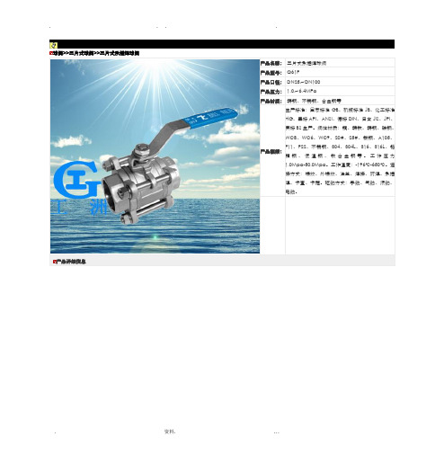
产品名称:三片式承插焊球阀
产品型号:Q61F
产品口径:DN25~DN100
产品压力:1.0~6.4MPa
产品材质:铸钢、不锈钢、合金钢等
产品概括:生产标准:国家标准GB、机械标准JB、化工标准HG、美标API、ANSI、德标DIN、日本JIS、JPI、英标BS生产。
阀体材质:铜、铸铁、铸钢、碳钢、WCB、WC6、WC9、20#、25#、锻钢、A105、F11、F22、不锈钢、304、304L、316、316L、铬钼钢、低温钢、钛合金钢等。
工作压力1.0Mpa-50.0Mpa。
工作温度:-196℃-650℃。
连接方式:螺纹、外螺纹、法兰、焊接、对焊、承插焊、卡套、卡箍。
驱动方式:手动、气动、液动、电动。
产品详细信息
球阀系列价格
供用户或工程项目做预算。

FLUID CONTROL DIVISIONParker Hannifin Corporation95 Edgewood AvenueNew Britain, CT 06051Telephone (860) 827-2300IOM 304Fax (860) 827-2384 (Rev B)INSTALLATION, OPERATING & MAINTENANCE INSTRUCTIONS3-WAY NORMALLY CLOSED, 3-WAY NORMALLY OPENAND 3-WAY UNIVERSALDIRECT ACTING VALVESSERIES 304GENERAL SAFETY INSTRUCTIONS BEFORE INSTALLATIONFAILURE OR IMPROPER SELECTION OR IMPROPER USE OF THE PRODUCTS AND/OR SYSTEMS DESCRIBED HEREIN OR RELATED ITEMS CAN CAUSE DEATH, PERSONAL INJURY AND PROPERTY DAMAGE.Both the conduit coil and leaded one-piece coil contain a green “grounding” wire that must be secured to a proper ground location.DO NOT cut off the green ground wire. Doing so could negate a proper ground path and leave the valve assembly unprotected or “hot”.This document and other information from Parker Hannifin Corporation, its subsidiaries and authorized distributors provide product and/or system options for further investigation by users having technical expertise. It is important that you analyze all aspects of your application, including consequences of any failure, and review the information concerning the product or system in the current product catalog. Due to the variety of operating conditions and applications for these products or systems, the user, through its own analysis and testing, is solely responsible for making the final selection of the products and systems and assuring that all performance, safety and warning requirements of the application are met.The products described herein, including without limitation, product features, specifications, designs, availability and pricing, are subject to change by Parker Hannifin Corporation and its subsidiaries at any time without notice.Carefully read installation, operation and maintenance procedures prior to installing or servicing valve.Do not use valve as a safety shut-off valve when making repairs. Do not install a valve before depressurizing system down to atmospheric pressure.Care must be taken to ensure that the valve materials selected are suitable for the media being handled. Parker assumes no liability for damage caused by improper material selection.Caution: Do not, at any time, make any alteration or modifications to any valve without the express and written approval of Parker’s Fluid Control Division.DESCRIPTIONThese valves are 3-way direct operated valves. The 304 series valve product line are available as Normally Closed (N.C.), Normally Open (N.O.), or universal (U) valves. The direct acting valves operate with zero pressure differential.Valves may be ordered with either NEMA 2, 4, 4X integrated coils for ordinary locations. Additional solenoid coils and enclosures are offered as described in our catalog.FLUID CODESListed below are the common fluid codes. The codes for the approved fluids for use with each valve are printed on the outside of the individual packaging.CODE FLUIDA - Air or nontoxic, nonflammable gasesAC - AcetyleneG - City gas supplied by public utilieisGA - GasolineHO - Petroleum based oils having viscosities up to 400SSU at 38°F02 No1 and No 2 fuel oils with viscosities lessthan 40SSU at 38°COX - OxygenW Water or other aqueous nonflammable liquidsFor the maximum fluid temperatures, as well asvalve ambientlimitations, check the valve part number on the nameplate and refer to the catalog.TORQUE CHARTINSTALLATION INSTRUCTIONS Installation must be done according to all applicable Safety Codes and Standards and by qualified personnel.Inspect valve prior to installation. Damaged valves oractuators must not be installed.Mounting position and pressure limits: Valves can bemounted directly on piping or by using the two #8-32 UNF threaded holes in the bottom of the valve body for the 1/8” NPT valves. Two #10-32 UNF threaded holes for the 1/4” NPT valves. The valves are designed to operate in any position. The valve may be installed in any line regardless of the direction in which the line runs. However, for optimum life and performance, the valve should be mounted vertically upright so as to minimize wear and reduce the possibility of foreign matter accumulating inside the sleeve area. Line pressure, voltage and frequency must conform to nameplate rating. Allow adequate clearance above valve for removal of coil. WARNING: Do not install a valve whose permitted pressure / temperature ratings are inadequate to meet the operating conditions. Piping: Remove protective closures from the ports. Connect line pressure to the inlet port and apparatus piping to the outlet port. Use of Teflon™ tape, threaded coumpounds or sealants is permissible but should be applied sparingly to male pipe threads only. CAUTION : Do not allow foreign particles, Teflon tape, or thread compound to enter valve. Only the wrench flats provided on the body ports should be used in applying the torque. Ports should not be subjected to excessive torque by use of an oversized wrench, wrench extension or by impacting the wrench handle. Do not use the valve to “stretch” or “align” the pipe. Tightening torque should not exceed 100 in-lbs for 1/8” NPT valves and 175 in-lbs [20,0 Nm] for 1/4” NPT valves. Do not use sleeve or enclosure as a lever when applying torque.Media filtration: For protection of the valve, install a suitable strainer or filter in the inlet side as close to the valve as possible. Dirt or foreign material in the media may cause excessive leakage, wear, or in exceptionalcases, malfunction. Clean periodically depending on service conditions. Lubrication: Lubrication is not required although air linelubrication will substantially increase valve life. Electrical connection: Electrical supply must conform to nameplate rating. Connect coil leads or terminals to the electrical circuit using standard electrical practices in compliance with local authorities and the National Electrical Code. Do not power coil until it has been fitted over sleeve and the retaining nut has been installed to prevent possible coil damage from overheating. WARNING : Turn off electrical power before connecting the valve to the power source. If the coil assembly is located in an inconvenient orientation, it may be reoriented to facilitate installation. Loosen coil assembly nut, rotate coil assembly to desired position, then retighten the retaining nut with an input torque per chart. COIL ASSEMBLY Position coil (as described below) on the sleeve, position and tighten retaining nut into the top of the sleeve assembly using a 5/32” or 5mm hex wrench with an input torque per chart. If the coil orientation needs to be repositioned to meet installation wiring needs, simple loosen the retaining nut usi ng a 5/32” or 5mm hex wrench , then rotate the coil to the required position and tighten the retaining nut. NOTE : The one-piece integrated coil assembly contains top and bottom o-ring seals to prevent moisture ingressioninto the sleeve area. The o-ring seals must be installed correctly for proper functionality. PORT MARKING ARRANGEMENTDe-Energized Energized11 33333One-Piece Integrated Coil. The conduit coil meets NEMA 2, 4, 4X classification for ordinary location requirements. Use suitable electrical cabling and conduit materials and components meeting applicable NEMA recommendations.For both the conduit and leaded one-piece coils, slide one o-ring over and down the sleeve assembly until the o-ring rests on the valve body., Slide the coil over the valve sleeve. Place the second o-ring into the recess located on top of the coil. Affix retaining nut to sleeve and tighten per torque chart. Use suitable electrical cabling for wiring connection.WARNING: Both the conduit coil and leaded one-piece coil contain a green “grounding” wire that must be secured to a proper ground location. The grounding wire is welded to the internal coil frame providing the approved ground path for the total valve assembly.DO NOT cut off the green ground wire. Doing so could negate a proper ground path and leave the valve assembly unprotected or “hot”.One-Piece DIN Coil and various cable option terminations:Loosen cable screw and remove plastic housing from DIN coil. Do not remove the gasket from the DIN spades on the coil. Separate the plastic block from the housing with a small screwdriver to expose the elecctrical terminations. Feed the lead wires through the conduit hub and attach them to the appropriate screw terminal. For electrical connection within the terminal box, use field wire that is rated for 90o C or greater. Snap the plastic block back into place inside the metal enclosure. Replace the cover and hand-tighten the cover screws. Place the gasket over the DIN spades on the coil and press the terminal box and coil together. Secure the terminal box to the coil using the mounting screw provided.Slide one o-ring over and down the sleeve assembly until the o-ring rests on the valve body. Slide the DIN coil over the valve sleeve. Place the second o-ring into the recess located on top of the coil. Affix retaining nut to sleeve and tighten per torque chart.Two-Piece Yoke & Spade Coil with 1/4” tabs: With coil inserted inside of U-shaped metal yoke, slide coil over sleeve. Affix retaining nut to sleeve and tighten per torque chart. Connect spade termination connector to spade tabs on coil.Two Piece Yoke & Molded Leaded 2-Wire Coil: With coil inserted inside of U-shaped metal yoke, slide coil over sleeve. Affix retaining nut to sleeve and tighten per torque chart. Use suitable electrical cabling for wiring connection. Two Piece Grommet Housing & Taped 2 Wire Coil: With the taped coil inserted inside the metallic housing, slide coil over sleeve. Affix retaining nut to sleeve and tighten per torque chart. Use suitable electrical cabling for wiring connection.Coil/enclosure temperature:The direct acting valves are supplied with coils designed for continuous duty service. Normal free space must be provided for proper ventilation. When the coil is energized continuously for long periods of time, the coil assembly will become hot. The coil is designed to operate permanently under these conditions. Any excessive heating will be indicated by smoking and/or odor of burning coil insulation.For the maximum valve ambient conditions, as well as the fluid temperatures, check the valve part number on the nameplate and refer to the product catalog to determine the maximum temperatures.MAINTENANCENote: While the valves are design to operate over millions of cycles, depending on service conditions, fluid being used, filtration, and lubrication, it may be required to periodically clean and/or replace worn components to ensure optimum quality performance. See Disassembly Instructions.CAUTION:Do not expose plastic or elastomeric materials to any type of commercial cleaning fluid. Parts should be cleaned with a mild soap and water solution.If a valve is to be removed from a pipeline carrying hazardous media, the parts of the valve in contact with the hazardous media must be properly cleaned and decontaminated before repairs are performed.DISASSEMBLY INSTRUCTIONSWARNING:Depressurize system and turn off electrical power to the valve before attempting repair. The coil must not be energized unless it is installed on the valve. Otherwise, the coil will overheat and burn out.The valve body need not be removed from the line.CAUTION:When removing or replacing the sleeve assembly, it may be necessary to provide proper support to prevent the valve from rotating thereby causing damage to piping.To remove the coil assembly:Using a 5/32” or 5mm hex wrench, unscrew the top retaining nut of the coil assembly. The coil assembly can be lifted off the sleeve tube.To disassemble the pressure vessel:Use the same 5/32” or 5mm hex wrench turning counterclockwise to remove the sleeve tube. The plunger assembly, return spring and o-ring seal may be removed. Replacement Parts: When ordering replacement parts kits, specify valve number and voltage from nameplate. Parts kits are available for each valve. Parts included in each kit are marked with an asterisk (X). See exploded views.PRESSEURE VESSEL REASSEMBLY INSTRUCTIONSTo reassemble the pressure vessel, refer to exploded view drawings. Parts must be replaced in the order shown.Lubricate o-ring with a mineral oil or equivalent and replace the o-ring into the valve body. Install the plunger and spring into the sleeve. Carefully align threads while installing the sleeve into the body.Tighten the sleeve assembly in the body using the 5/32” or 5mm hex wrench turning clockwise with an input torque per torque chart.COIL REASSEMBLY INSTRUCTIONSWith coil assembly repositioned on the sleeve, position the retaining nut into the top of the sleeve assembly and tighten using a 5/32” or 5mm hex wrench with an input torque of of 25-35 in-lbs [2,9 to 4,0 Nm].LABELINGMODULAR LABELINGFor valves sold modularly, a 2-piece label system is used consisting of a base valve identification label and a coil identification overlay label. The base label is affixed to the coil and the overlay label is placed over the base label provide the complete valve identification.VALVE IDENTIFICATIONAll Parker pressure vessels are identified with a valve label. The label indicates the valve part number, maximum operating pressure differential (MOPD), orifice size and date code.FLUID CONTROL DIV NEW BRITAIN, CT USADATE CODE ORIFICE 1207O 7/64 PRESSURE VESSEL30CC02MV4WATTS 10AC 8.5DCAC 50 PSIDC 50 PSICOIL IDENTIFICATIONAll Parker coil enclosures are identified with a label. The label indicates the coil part number, voltage and frequency.FLUID CONTROL DIV NEW BRITAIN, CT USAVOLTS/HZ24VDCENCL & B4BCOILFULLY ASSEMBLED VALVE LABELINGAll Parker valves are identified with a valve label. The label indicates the valve type and size, maximumoperating pressure differential (MOPD), orifice size and applicable agency approval designations. In addition, the label also specifies the appropriate electrical specifications for agency compliance.FLUID CONTROL DIV NEW BRITAIN, CT USAVALVE NUMBER30CC02MV4B2BVOLTS/HZ 24VDCWATTS 8.5 ORIFICE 7/64 3/32PSI50BAR3CODE0907OPARTS LIST AND COMPONENT DRAWINGRetaining NutComplete Portfolio of Available CoilsDECLARATIONParker’s Fluid Control Division certifies its valve appliance products complies wit h the essential requirements of the applicable European Community Directives. We hereby confirm that the appliance has been manufactured in compliance with the applicable standards and is intended for installation in a machine or application where commissioning is prohibited until evidence has been provided that the machine or application is also in compliance with EC directives.The data supplied in the Parker valve catalogs and general Installation, Operating & Maintenance Instructions are to be consulted and pertinent accident prevention regulations followed during product installation and use. Any unauthorized work performed on the product by the purchaser or by third parties can impair its function and relieves Parker Hannifin of all warranty claims and liability for any misuse and resulting damage.A separate Declaration of Conformity or Manufacturer’s declaration is available upon request. Please provide valve identifica tion numbers and order serial numbers of products concerned.。

三阀组一、主要性能规范:型号Type 公称压力PNMpa试验压力PS(Mpa)_Test pressure工作压力(Mpa)Working pressure工作温度(OC)Working temps.适用介质Applicable medium 壳体Shell密封(液)Seal 密封(气)Seal1151-40 4.0 6.0 4.4 0.6 4.0 P≤540OC液化石油气水,酸,蒸汽,油品等Petroleum gasWater,As,Steam,1151-320P 32.0 48.0 35.2 0.6 32.0 C≤425 OCOil,etc.二、三阀组主要外形及连接尺寸:公称直径DN(mm)尺寸 Dimension重量(kg)Weight Do D1 H L L1 d3-6 60 97 220 87 54 3-6 2.2订货须知:一、①三阀组产品名称与型号②三阀组口径③三阀组是否带附件二、若已经由设计单位选定公司的三阀组型号,请按三阀组型号三、当使用的场合非常重要或环境比较复杂时,请您尽量提供设计图纸和详细参数,相关产品:QFF3阀组针型阀针型仪表阀J13W高压内螺纹针型阀J23W铬镍不锈钢焊接针型阀J29H针型仪表阀J49H不锈钢仪表针型阀不锈钢针型仪表阀针型阀JJY1卡套针型阀J13W型针型阀J24W角式高压针型阀CJ123F型针型阀J19H压力表针型阀液化石油气针型阀J61Y焊接针型阀J23SA型针型阀JJM8不锈钢压力表针型阀其它阀系列价格供用户或设计院工程项目做预算管夹阀价格表口径手动电动DN50 450 1350 DN65 690 1575 DN80 1020 3375 DN100 1500 4050 DN125 1950 4500 DN150 **** **** DN200 4350 8400 DN250 7050 9750 DN300 12450 17700 DN350 21450 71700 DN400 29250 35400电动二通阀价格名称型号通径价格三速温控开关液晶显示温控开关大中小电动二通阀(风机管盘)VA70101.6mpa≤180℃DN15 87 37.5 78 75 72DN20 87 37.5 78 75 72DN25 127.5 37.5 78 75 72 HYDF1.6mpa≤120℃DN15 97.5 34.5 78 75 72DN20 97.5 34.5 78 75 72DN25 127.5 34.5 78 75 72名称通径价格电动二通阀DN25 600配套驱动器,传感器,变压器,温度控制器DN32 630 DN40 675 DN50 720 DN65 1125 DN80 1575 DN100 1725 DN125 2100 DN150 23400 DN200 3450 DN250 5250 DN300 7800 DN350 9750 DN400 12900产品名称通径DN工作压力(mpa)1.6(Z)2.5(c)Y416XY110X 减压稳压阀25/110 225 270 32/110 285 345 40/110 315 382.5 50/110 345 42050 585 70565 630 75080 757.5 900 100 915 1095 125 1470 1770 150 1800 21750JM744X气动,液动快开排泥阀80 825 990 100 900 1080 125 1575 1890 150 **** **** 200 1950 2340 250 3150 3780 300 4650 5580产品公称工作压名称通径(mpa)1.0/1.6CARX 复合式排气阀DN20DN25DN32DN40 507 DN50 507 DN65 591 DN80 637.5 DN100 675 DN125 862.5 DN150 1125 DN200 2250产品名称公称通径工作(mpa)1.0/1.6排气阀DN40 216 DN50 216 DN65 262.5 DN80 300 DN100 328.5 DN125 337.5 DN150 394.5 DN200 694.5 DN250 1125 DN300 1500 DN350底阀价格底阀H42F-6P口径4Ni 8Ni 普料DN15DN20DN25DN32DN40 172.5 217.5 135 DN50 240 277.5 150 DN65 315 382.5 210 DN80 457.5 517.5 277.5 DN100 525 570 307.5 DN125 720 900 540 DN150 **** ****.5 757.5 DN200 1650 2182.5 1140 DN250 2400 2775 1650 DN300 3450 3975 2625型号口径单位单价(元)双门底阀DN40 只255 DN50 只300 DN80 只495电动二通阀价格名称型号通径价格三速温控开关液晶显示温控开关大中小电动二通阀(风机管盘)VA70101.6mpa≤180℃DN15 87 37.5 78 75 72DN20 87 37.5 78 75 72DN25 127.5 37.5 78 75 72 HYDF1.6mpa≤120℃DN15 97.5 34.5 78 75 72DN20 97.5 34.5 78 75 72DN25 127.5 34.5 78 75 72名称通径价格电动二通阀配套驱动器,传感器,变压器,温度控制器DN25 600 DN32 630 DN40 675 DN50 720 DN65 1125 DN80 1575 DN100 1725 DN125 2100DN150 23400DN200 3450DN250 5250DN300 7800DN350 9750DN400 12900呼吸阀阻火器价格型号呼吸阀GFQ-2 阻火呼吸阀ZFQ-1 呼吸阀QZF-89 口径铸钢不锈钢铸钢不锈钢铸钢不锈钢DN25 187.5 450 255 502.5 //DN32 262.5 585 315 675 //DN40 277.5 660 330 705 //DN50 315 727.5 360 795 765 1905 DN65 397.5 922.5 465 1125 1005 2505 DN80 465 1170 555 1327.5 1080 2760 DN100 585 1417.5 705 1590 1215 3120 DN125 727.5 2100 915 2280 2085 4485 DN150 952.5 2415 1125 2670 2715 5880 DN200 1425 3367.5 1635 3795 3135 8625 DN250 1897.5 4560 2250 5355 4485 11115 DN300 3360 6555 3825 7905 5700 15015型号管道阴火器GYW-1 管道阻火器GZW-1 阻火器ZGB-1 口径铸钢不锈钢铸钢不锈钢铸钢不锈钢DN25 210 420 240 555 210 420 DN32 285 675 315 900 255 570 DN40 315 765 345 1005 270 600 DN50 360 870 390 1170 315 690 DN65 420 1125 465 1635 345 840 DN80 555 1380 600 1815 450 1035 DN100 660 1635 720 2250 555 1305 DN125 810 2325 1005 3795 660 1980 DN150 **** **** 1350 4830 915 2325 DN200 1635 4320 1980 6645 1290 3150 DN250 2325 5865 2670 9495 1635 4395阻火透气帽公称通径铝合金铸钢不锈钢单价(元)单价(元)DN40 105 150 420 DN50 105 195 450 DN80 210 375 780 DN100 345 450 990 DN150 825 810 1635 DN200 1020 1065 2595型号公称通径铸钢不锈钢单价(元)单价(元)网型阻火器HGS一07DN25 382.5 570 DN40 630 1050 DN50 697.5 1125 DN65 900 1695 DN80 1035 1905 DN100 1417.5 2505 DN150 **** **** DN200 4050 7245 DN250 4275 10530 DN300 6007.5 13455管道砾石阻火器口径DN25 DN50 0N65 DN80 DN100 DN150 铸钢375 600 690 780 1080 1635流量计价格名称通径价格LDE智能型电磁流量计DN15 3300 DN20 3300 DN25 3300 DN32 3450 DN40 3450 DN50 3450 DN65 3450 DN80 3450 DN100 3600DN125 3750DN150 4050DN200 4800DN250 5700DN300 7200DN350 7800DN400 9300DN500 10800DN600 13500DN700 16500DN800 21750DN900 24750DN1000 28500DN1200 36000 名称通径价格涡街流量计DN25 3450 DN32 3525 DN40 3600 DN50 3750 DN65 3900 DN80 4275 DN100 4500 DN125 5250 DN150 6300 DN200 8250 DN250 9750 DN300 11700水处理器价格多功能微电子水处理器DN20 1125 DN25 1125 DN32 1200 DN40 1200 DN50 1200DN65 1275DN80 1350DN100 1500DN125 1650DN150 1875DN200 2400DN250 3000DN300 3600DN350 4200DN400 5700DN450 6750DN500 8400DN600 9000DN700 12750DN800 16500DN900 21000DN1000 24750 名称通径价格内磁水处理器DN25 1500 DN32 1650 DN40 1725 DN50 1950DN6522502550 DN80 2550 DN100 3000 DN125 3750 DN150 4350 DN200 5700 DN250 7350 DN300 8700 DN400 11250 DN500 14250 DN600 18000橡胶接头价格KXT(JGD)可曲挠 橡胶接头 规格单球单球翻边 单球翻边双球变径球l.OMPa 1.6MPa 2.5MPa l.OMPa 1.6MPa 1.OMPa 规格型号1.OMPaDN25 61.5 61.5 118.5 DN32 99 99 165 65×50 313.5 DN40 108 108 174 111 80×65 394.5 DN50 115.5 115.5 214.5 120 165 100×65 435 DN65 151.5 151.5 280.5 162 202.5 100×80 472.5DN80 169.5 169.5 313.5 175.5250.5 100×125 571.5 DN100 198 198 346.5 208.5292.5 100×150 708 DN125 300 300 561 334.5 442.5 125×150 708DN150 351 351 750 417 457.5 538.5 200×100 1170 DN200 487.5 544.5 1125 624 690 703.5 200x125 1170 DN250 646.5 792 1560 867 952.5 1056 200x150 1170 DN300 888 1015.5 2205 1224 1350 1287 250×125 1497 DN350 1023 1270.5 2352 1306.5 1440 2118 250×150 1497 DN400 1339.5 1639.5 3255 1809 1995 2178 250×200 1497 DN450 1617 2178 4200 22885.5 2565 0 300X200 1665 DN500 1815 2722.5 5460 3033 3337.5 4290 300×250 1665 DN600 2392.5 8070 4483.5 4935 6154.5 350X200 1873.5KXT(JGD) 可曲挠橡胶接头规格单球单球翻边 单球翻边双球变径球l.OMPa 1.6MPa 2.5MPa l.OMPa 1.6MPa 1.OMPa规格型号1.OMPa DN700 3157.5 9892.5 5494.5 6045 7590 350*300 1873.5 DN800 429012022.5 6679.57350 8745 400*300 2068.5 DN900 53137986 8790 0 400*350 2236.5 DN1000 61359438 10380 12243 1200*800 32670DN1100 8250 0 备注 以上产品橡胶为天然胶, 法兰锻钢。

全焊接球阀Q 3/6/9 6 1/7 F使用说明书上海双高阀门集团有限公司一、用途:城市煤气:煤气输出管道、主干线及各支线供应管道等。
集中供热:大型供热设备输出管线、主干线、支线。
热交换机:管道及各回路启闭。
钢铁厂:各种流体管道、废气择放管道、煤气和热力供应管道、燃料供应管道。
各种工业设备:各种热处理管道、各种工业煤气和热力管道。
二、特性:整体式焊接球阀,不会有外部泄漏等现象。
由于阀座是由碳化特氟隆密封环及咖弹簧构成的,所以对压力和温度的变化适应能力强,在标注压力和温度范围内不会产生任何泄漏。
球体的加工过程有先进的计算机检测仪跟踪检测,所以球体的加工精度高。
由于阀体材料跟管道材质一样,不会出现应力不均,也不会由于地震及车辆经过地面时而产生变形,管道耐老化。
密封环本体采用含量25%Carbon(碳素)的CPTFE材质,保障完全无泄漏(0%)。
直埋式焊接球阀可以直接埋于地下,不用建高大型阀门井,只需在地面上设置小型浅井,大大节省施工费用及工程时间。
可根据管道的施工及设计要求,调整阀体的长短和阀杆的高度。
球体的加工精度非常精密,操作轻便,无不良干涉。
采用高级的原材料,能保PN25以上的压力。
与同类行业的同种规格产品相比,阀体小,而且外型美观。
在保证阀门正常操作、使用情况下,质保20年。
三、阀门的结构特点1.带锁装置和开闭无误定位装置:本阀门没有带锁装置,如果阀门在特殊情况下可以设计成带锁装置,这样有利于安装在室外的阀门防止闲杂人操作。
开闭无误装置,我们的球阀开闭度的确认通常是根据开关指示标志来决定,当指示标记和管道平行时,阀门处于开启位置,和管道垂直时,阀门处于关闭位置。
(备注:如需其他要求,请在订单中说明)2.防火结构:为防止火灾或骤热的出现使聚四氟乙烯阀座及填料烧损时,发生较大泄漏而助长火势,我们在密封面和阀杆上设计了注脂阀在球体阀座间设置了防火密封环和弹簧,在阀座烧损后,弹簧将阀座迅速推向球体上,注脂阀注入润滑脂注入到阀座和阀杆上,形成金属接触,和润滑脂的双重作用,起到一定程度的密封,从而保证系统的安全。

附件一:SAMSON 气动控制阀规格一览表及供货清单SAMSON PNEUMATIC CONTROL VALVE SPECIFICATION LIST AND THE SUPPLY CHECKLIST制造商:SAMSON AGe m / 序号a g N O . / 设计位号t y / 数量y p e / 型号N / 口径N u n i t s t a n d a r d / 压力单位N /C l a s s / 压力等级o d y M a t e r i a l / 阀体材质l a n g e f o r m / c o n n e c t i o n / 法兰形式/连接a c k i n g / 填料l u g / s e a t m a t e r i a l / 阀芯/阀座材质e a k a g e / 泄漏等级r e s s u r e b a l a n c e d / 压力平衡阀芯h a r a c t e r i s t i c / 流量特性v -v a l u e / 选择C v 值o i s e r e d u c t i o n / 减噪器l o w d i r e c t i o n / 流向o n n e t / 阀盖形式c t u a t o r t y p e / 执行器类型c t u a t o r s i z e [c m 2] / 执行器膜头面积t r o k e [m m ] / 行程a n d w h e e l / M a n u a l / 手轮/手动装置p r i n g r a n g e [b a r ] / 弹簧范围[b a r ]a i l s a f e p o s i t i o n / 故障安全位置o s i t i o n e r / 定位器o l e n o i d v a l v e / 电磁阀i m i t s w i t c h e s / 限位开关i r s e t s w i t h f i l t e re m a r k / 备注I t T Q T D P P B F P P L P C C N F B A A S H S F P S L a R 1HV-311057135101"CLASS 1500A316Ti RJ PStellite 6B IV -log 0.5-FTC IT 32771207.5Y0.4 ... 0.8FCY1Y22HV-312057HV-313057HV-314057HV-315057432561"CLASS1500A216 WCCRJG Stellite 6BIV -log 3-FTC std327735015Y0.2 (1)FCY1Y2Total:5Note:1. Electropneumatic Positioner 3730-3:HART,EEx ia IIC T6, Elec.Conn.: 1/2 NPT2. Air Set 4708:low temperature version3. IT=Extended 角型调节阀-5台.xlsSeite 12010-6-26Valve Sizing Version 4.76Item no.01Tag no.HV-311057Process mediumboiler blowdownState of medium at inlet:liquidProcess and medium dataCase 1Case 2Case 3FlowInlet pressureInlet temperature W p1Differential pressure dp t1[kg/h][bar(g)][bar][°C]82108.6268.93317137108.6268.88317687.1108.6167.99317DensityVapor pressure Critical pressure Viscosityrho1pv pc eta [kg/m³][MPa(a)][MPa(a)][mPas]67510.8422.120.01867510.8422.120.01867510.8422.120.018Flashing portion Densityxd2rho2[%][kg/m³]20.327220.7720.327220.7720.327220.77Results and factorsValve coeff. calculated Min. req. size Outlet velocitySPL VDMA 24422 mod. Flow condition CvLA Req. DN w ["][m/s][dB(A)]0.02350.03920.1975355630.115"0.5090.149"0.8500.334"4.26Flashing Flashing Flashing relative travelDifferent. pressure ratio FL value xFmr valueValve style factor T [%]xF FL xFmr Fd 23.855.900.950.800.0936.955.860.950.800.1178.155.590.950.800.25xFz value at load xFz 0.800.800.80Level exponent Slope exponent Correct. termF1F2delta Lf [dB]-8.28-8.27-8.060.300.300.3018.2818.2818.21Valve dataBody typeMicro valve Series Type3510Valve coefficient Cv 0.5Nominal size DN ["]1"Pressure ratings CLASS 1500Travel S 7.5Seat bore SB 4[mm][mm]Body material A316Ti Noise reduction without Charact.Equal perc.Flow direction FTCStem diameterSd 4[mm]Balanced without (0.0)Internal parts material Stellite 6B Leakage rate IVPacking PTFE (3.2)Sealingmetal (2.0)Bonnetinsulating sPipe dataType of pipe Steel pipe Pipe insulation noneD1["]2"D2["]2"cR 5100rho 7800di 42.8s 8.7[m/s][kg/m³][mm][mm]Actuator dataType3277Fail-safe act.extends Bench range ps0 0.4 ... 0.8Diaphr. areaA 120Supplypsu 2.4[bar][cm²][bar][bar(g)][bar(g)][°C](Defaults:p1max 122.4p2mint1max325)Actuator resultsreq. act. force Fo req.0.22req. diff. psu-ps100 d ps 0.04max. act. force Fmax 10.22Actuator forceFa 0.48[kN][bar][kN][kN]Valve Sizing Version 4.76Item no.02Tag no. HV-312057/313057/314057/315057Process mediumboiler blowdownState of medium at inlet: liquidProcess and medium dataCase 1Case 2Case 3FlowInlet pressureInlet temperature Wp1Differential pressure dp t1[kg/h][bar(g)][bar][°C]496109.870.2318827109.870.131********.668.7318DensityVapor pressure Critical pressure Viscosityrho1pv pc eta [kg/m³][MPa(a)][MPa(a)][mPas]67210.9522.120.01867210.9522.120.01867210.9522.120.018Flashing portion Densityxd2rho2[%][kg/m³]20.327220.7720.327220.7720.327220.77Results and factorsValve coeff. calculated Min. req. size Outlet velocitySPL VDMA 24422 mod. Flow condition CvLA Req. DN w ["][m/s][dB(A)]0.1810.301 1.497073810.284"3.080.367"5.130.822"25.7Flashing Flashing Flashing relative travelDifferent. pressure ratio FL value xFmr valueValve style factor T [%]xF FL xFmr Fd 30.953.470.740.700.1441.653.390.740.700.2079.761.730.750.700.56xFz value at load xFz 0.550.550.56Level exponent Slope exponent Correct. termF1F2delta Lf [dB]-7.75-7.62-7.130.300.300.3020.3520.3220.44Valve dataBody typeAngle valve Series 250Type3256Valve coefficient Cv 3Nominal size DN ["]1"Pressure ratings CLASS 1500Travel S 15Seat bore SB 12[mm][mm]Body material A216 WCC Noise reduction without Charact.Equal perc.Flow direction FTCStem diameterSd 12[mm]Balanced without (0.0)Internal parts material Stellite 6B Leakage rate IVPacking Graphite (10)Sealingmetal (2.0)BonnetstandardPipe dataType of pipe Steel pipe Pipe insulation noneD1["]2"D2["]2"cR 5100rho 7800di 49.3s 5.5[m/s][kg/m³][mm][mm]Actuator dataType3277Fail-safe act.extends Bench range ps0 0.2 (1)Diaphr. areaA 350Supplypsu 1.2[bar][cm²][bar][bar(g)][bar(g)][°C](Defaults:p1max 122.4p2mint1max325)Actuator resultsreq. act. force Fo req.0.45req. diff. psu-ps100 d ps 0.12max. act. force Fmax 24.81Actuator forceFa 0.70[kN][bar][kN][kN]。
三片式焊接球阀尺寸标准在焊接球阀的尺寸标准中,三片式焊接球阀是其中的一种常见类型。
本文将对三片式焊接球阀的尺寸标准进行详细介绍。
一、三片式焊接球阀的概述三片式焊接球阀是一种以球体为阀体,通过旋转球体实现流体控制的阀门。
它由阀体、球体和阀盖三个主要部件组成,通常采用焊接方式连接。
该阀门具有结构紧凑、密封可靠、使用寿命长等特点,广泛应用于石油、化工、冶金等工业领域。
二、三片式焊接球阀尺寸标准的重要性三片式焊接球阀的尺寸标准对于确保阀门的互换性、安装配套性以及流体控制的精准性十分重要。
只有符合标准的尺寸才能确保阀门的性能和使用效果。
三、三片式焊接球阀尺寸标准的内容三片式焊接球阀的尺寸标准一般包括以下几个方面:1. 球阀口径:球阀口径是指球阀的流道内径,其大小决定了阀门的流量通道大小。
通常,三片式焊接球阀的口径范围从1/2英寸到48英寸不等。
2. 球阀连接方式:三片式焊接球阀可采用不同的连接方式,如焊接连接、法兰连接等。
标准中应指明阀门的连接方式及其相关尺寸。
3. 阀体尺寸:阀体尺寸包括长度、宽度、高度等方面的尺寸参数,这些参数对于阀门的安装、维修和配套具有重要意义。
4. 阀盖尺寸:阀盖是三片式焊接球阀的重要组成部分,其尺寸标准应指明阀盖的外径、螺纹规格、法兰尺寸等参数。
5. 其他尺寸参数:除了上述主要尺寸外,还需包含阀杆、密封面直径、焊接接头尺寸等其他重要尺寸参数。
四、三片式焊接球阀尺寸标准的制定机构与应用范围三片式焊接球阀的尺寸标准由国际标准化组织(ISO)、美国石油学会(API)、中国石油和化学工业标准(GB)等制定并发布。
这些标准适用于各类石油化工设备中的三片式焊接球阀。
五、三片式焊接球阀尺寸标准的意义和挑战三片式焊接球阀尺寸标准的制定,可以实现不同厂家生产的阀门互换使用,提高设备的灵活性和可维护性。
然而,由于行业需求的多样化和技术创新的不断推进,标准的制定也面临着挑战,需要不断更新和完善。
六、结论三片式焊接球阀作为一种重要的流体控制阀门,在工业生产中发挥着重要作用。
球阀>>三片式球阀>>三片式球阀产品详细信息球阀系列价格供用户或设计院工程项目做预算一、阀门的选型步骤1.明确阀门在设备或装置中的用途,确定阀门的工作条件:适用介质、工作压力、工作温度等等。
2.确定与阀门连接管道的公称通径和连接方式:法兰、螺纹、焊接等。
3.确定操作阀门的方式:手动、电动、电磁、气动或液动、电气联动或电液联动等。
4.根据管线输送的介质、工作压力、工作温度确定所选阀门的壳体和内件的材料:灰铸铁、可锻铸铁、球墨铸铁、碳素钢、合金钢、不锈耐酸钢、铜合金等。
5.确定阀门的型式:闸阀、截止阀、球阀、蝶阀、节流阀、安全阀、减压阀、蒸汽疏水阀、等。
6.确定阀门的参数:对于自动阀门,根据不同需要先确定允许流阻、排放能力、背压等,再确定管道的公称通径和阀座孔的直径。
7.确定所选用阀门的几何参数:结构长度、法兰连接形式及尺寸、开启和关闭后阀门高度方向的尺寸、连接的螺栓孔尺寸和数量、整个阀门外型尺寸等。
8.利用现有的资料:阀门产品目录、阀门产品样本等选型适当的阀门产品。
二、阀门的选型依据1.所选用阀门的用途、使用工况条件和操纵控制方式。
2.工作介质的性质:工作压力、工作温度、腐蚀性能,是否含有固体颗粒,介质是否有毒,是否是易燃、易爆介质,介质的黏度等等。
3.对阀门流体特性的要求:流阻、排放能力、流量特性、密封等级等等。
4.安装尺寸和外形尺寸要求:公称通径、与管道的连接方式和连接尺寸、外形尺寸或重量限制等。
⑤对阀门产品的可靠性、使用寿命和电动装置的防爆性能等的附加要求。
(在选定参数时应注意:如果阀门要用于控制目的,必须确定如下额外参数:操作方法、最大和最小流量要求、正常流动的压力降、关闭时的压力降、阀门的最大和最小进口压力。
)根据上述选型阀门的依据和步骤,合理、正确地选型阀门时还必须对各种类型阀门的内部结构进行详细了解,以便能对优先选用的阀门做出正确的抉择。
管道的最终控制是阀门。
三片式承插焊球阀
名称: 三片式承插焊球阀 型号: Q61F
口径: DN6‐100
压力: 6.4MPa
材质: 铸钢、不锈钢
三片式承插焊球阀的概述
三片式承插焊球阀是用带有圆形通道的球体作启闭件,球体随阀杆转动实现启闭动作的阀门,其启闭件是一个有孔的球体,绕垂直于通道的轴线旋转,从而达到启闭通道的目的。
三片式承插焊球阀标准规范和适用范围
设计制造标准GB/T 12237-2007
结构长度标准GB/T 12221-2005
承插焊标准 GB12224、ANSIB16.25
压力温度等级GB/T 12224-2005
试验检验标准GB/T 13927-2008
适用介质水、油、气及某些腐蚀性液体(W.O.G)
介质温度 -20~232℃~350℃
公称压力 1.6-6.4MPa
三片式承插焊球阀结构特点
适用于经常操作,启闭迅速、轻便。
1. 流体阻力小。
2. 结构简单,相对体积小,重量轻,便于维修。
3. 密封性能好。
4. 不受安装方向的限制,介质的流向可任意。
5. 无振动,噪声小。
三片式承插焊球阀主要零件材料参数
零件名称材质
阀体不锈钢CF8M 碳钢WCB
密封圈聚四氟乙烯PTFE 聚四氟乙烯PTFE
阀盖不锈钢CF8M 碳钢WCB
球体不锈钢SS316 不锈钢SS304
阀杆不锈钢SS316 不锈钢SS316
螺母不锈钢SS304 FCD45
垫圈不锈钢SS304 FCD45
手柄套塑料塑料
手柄不锈钢SS304 不锈钢SS304 阀杆螺母不锈钢SS304 B7
填料压盖螺母不锈钢SS304 不锈钢SS304 填料聚四氟乙烯PTFE 聚四氟乙烯PTFE 止推垫圈聚四氟乙烯PTFE 聚四氟乙烯PTFE 螺栓不锈钢SS304 B8
三片式承插焊球阀主要尺寸及重量
SIZE 1/4" 3/8"1/2" 3/4" 1" 1-1/4"1-1/2"2" 2-1/2" 3" 4"
D 11.6 12.715 20 25 32 38 50 65 80 100
L 68 68 72 82 90 112 120 145185 210 268
H 50 50 60 64 71 78 86 95 130 148 173
E 100 100130 130 165165 190 190250 250 280
F 14.1 17.621.8 27.5 34.743.0 49.0 61.577.0 90.0 115.2
P 10 10 10 13 13 16 16 18 18 20 20 声明:本文中所有文字、数据、图片均只适用于参考。