变压器风扇中文说明书
- 格式:doc
- 大小:370.50 KB
- 文档页数:11
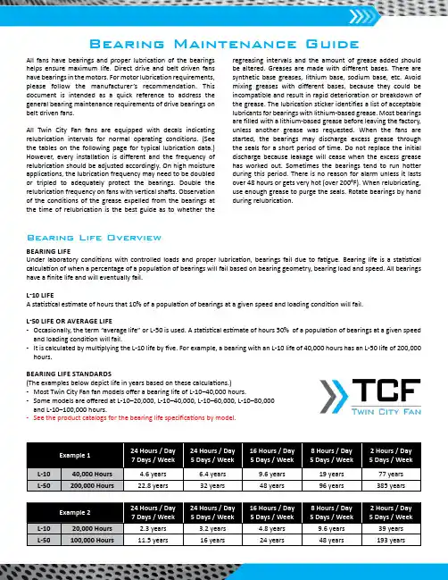
All fans have bearings and proper lubrication of the bearings helps ensure maximum life. Direct drive and belt driven fans have bearings in the motors. For motor lubrication requirements, please follow the manufacturer’s recommendation. This document is intended as a quick reference to address the general bearing maintenance requirements of drive bearings on belt driven fans.All Twin City Fan fans are equipped with decals indicating relubrication intervals for normal operating conditions. (See the tables on the following page for typical lubrication data.) However, every installation is different and the frequency of relubrication should be adjusted accordingly. On high moisture applications, the lubrication frequency may need to be doubled or tripled to adequately protect the bearings. Double the relubrication frequency on fans with vertical shafts. Observation of the conditions of the grease expelled from the bearings atthe time of relubrication is the best guide as to whether theBearing Maintenance Guideregreasing intervals and the amount of grease added should be altered. Greases are made with different bases. There are synthetic base greases, lithium base, sodium base, etc. Avoid mixing greases with different bases, because they could be incompatible and result in rapid deterioration or breakdown of the grease. The lubrication sticker identifies a list of acceptable lubricants for bearings with lithium-based grease. Most bearings are filled with a lithium-based grease before leaving the factory, unless another grease was requested. When the fans are started, the bearings may discharge excess grease through the seals for a short period of time. Do not replace the initial discharge because leakage will cease when the excess grease has worked out. Sometimes the bearings tend to run hotter during this period. There is no reason for alarm unless it lasts over 48 hours or gets very hot (over 200°F). When relubricating, use enough grease to purge the seals. Rotate bearings by hand during relubrication.BEARING LIFEUnder laboratory conditions with controlled loads and proper lubrication, bearings fail due to fatigue. Bearing life is a statistical calculation of when a percentage of a population of bearings will fail based on bearing geometry, bearing load and speed. All bearings have a finite life and will eventually fail.L-10 LIFEA statistical estimate of hours that 10% of a population of bearings at a given speed and loading condition will fail.L-50 LIFE OR AVERAGE LIFE- Occasionally, the term “average life” or L-50 is used. A statistical estimate of hours 50% of a population of bearings at a given speed and loading condition will fail.- It is calculated by multiplying the L-10 life by five. For example, a bearing with an L-10 life of 40,000 hours has an L-50 life of 200,000 hours.BEARING LIFE STANDARDS(The examples below depict life in years based on these calculations.)- Most Twin City Fan fan models offer a bearing life of L-10–40,000 hours.- Some models are offered at L-10–20,000, L-10–40,000, L-10–60,000, L-10–80,000 and L-10–100,000 hours.-See the product catalogs for the bearing life specifications by model.Bearing Life OverviewTWIN CITY FAN & BLOWER | WWW.TCF .COM5959 Trenton Lane N | Minneapolis, MN 55442 | Phone: 763-551-7600 | Fax: 763-551-7601©2022 Twin City Fan Companies, Ltd.Safety & Bearing Lubrication InstructionsIf you have additional questions, please contact your local Twin City Fan sales representative. To find your local sales representative, please visit .。
油浸式电力变压器安装服务手册本说明书适用于额定容量8000kVA及以上,额定电压220kV级及以下油浸式大型电力变压器,作为产品运输、装卸、贮存、安装运行等环节工作中基本技术要求和操作程序的指导性文件。
在使用本说明书时,应结合变压器的具体结构和订货合同(含技术协议)要求,参照相关国家、行业标准和有关组部件安装服务手册的技术要求进行施工。
如有疑问请与生产商联系以便妥善处理。
1、包装1.1 变压器的主体和附件分开运输。
变压器的主体、较长的导油管路、支架、净油器、储油柜、片式散热器及其控制箱、充满变压器油的套管型电流互感器组等,一般不包装运输,但所有管口应密封可靠,其中储油柜的玻璃管式油位计用木盒保护。
1.2 63kV级及以上电容式套管、冷却器及其控制箱等均单独包装。
1.3 片式散热器用风扇、40kV级及以下套管、吸湿器、硅胶、气体继电器、测温装置、较小的导油管路、联气管、小车、备件等,为集中包装。
1.4 一台变压器有多个包装箱时,箱体表面上有编号,装箱单与出厂文件一起包装运输。
2、运输与装卸2.1 运输要求2.1.1 带油运输的变压器,油箱内应充入合格的变压器油,油面高度离油箱顶,平顶时约100mm,梯形顶时约150mm。
密封可靠,无渗漏油现象。
2.1.2 充气(指纯氮气或干燥空气,以下同)运输的变压器,油箱内油面高度为下部放油阀管径上部约50mm。
应充入纯度大于99.9%、露点不高于-40℃的纯氮气或露点不高于-40℃的干燥空气,并应在油箱上部装置补充气体设备和压力表,保持油箱内正压力0.015~0.03MPa。
2.1.3运输装车和固定,按有关运输部门规定和要求执行。
特别提示必须利用上节油箱的吊拌和下节油箱的吊轴孔进行变压器固定,严禁使用加强铁工艺孔、升高座或法兰管等不能承受拉力的组附件。
完成装车后,应对索固件的位置进行有效的标记,以备运输过程中和到达目的地时测定位移情况。
2.1.4按照GB/T6451的要求,容量≥150MVA的变压器主体运输时应装冲撞记录仪;一般情况下,容量<150MVA的变压器主体运输时也应装冲撞记录仪。
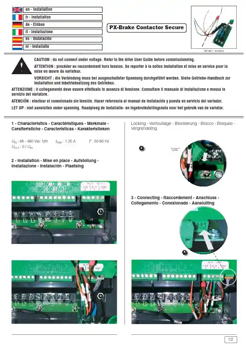
CAUTION : do not connect under voltage. Refer to the drive User Guide before commissionning.ATTENTION : procéder au raccordement hors tension. Se reporter à la notice Installation et mise en service pour lamise en œuvre du variateur.VORSICHT : die Verbindung muss bei ausgeschalteter Spannung durchgeführt werden. Siehe Getriebe-Handbuch zurInstallation und Inbetriebsetzung des Getriebes.ATTENZIONE : il collegamento deve essere effettuato in assenza di tensione. Consultare il manuale di installazione e messa in servizio del variatore.ATENCIÓN : efectuar el conexionado sin tensión. Hacer referencia al manual de instalación y puesta en servicio del variador.LET OP : niet aansluiten onder spanning. Raadpleeg de installatie- en ingebruikstellingsnota voor het gebruik van de variator.PX-Brake Contactor Secure1/24123PX-Brake Contactor Secure4.2 - Secure input - Entrée sécuritaire - Sicherheit- Eingange - Ingresso di sicurezza - Entrada de seguridad - VeiligheidsingangApplying secure input SDI2 together with digital input DI2.Complies to EN 954-1 category 2 or 3 safety standards without any line contactor.Utilisation de l'entrée sécuritaire SDI2 en redondance avec l'entrée logique DI2. Conforme à EN 954-1 catégorie 2 ou 3 sans contacteur de ligne.Verwendung des Sicherheits-Einganges SDI2 in Redundanz mit dem logischen Eingang DI2. Konform mit EN 954-1 Kategorie 2 oder 3 ohne Überstromschalter.Uso dell'ingresso di sicurezza SDI2 in ridondanza conl'ingresso logico DI2. Conforme a EN-954-1 categoria 2 o 3 senza contattore di linea.Uso de la entrada de seguridad SDI2 en redundancia con la entrada lógica DI2. Conforme a EN-954-1 categoría 2 ó 3 sin contactor de líneaGebruik van de veiligheidsingang SDI2 met de logische ingang DI2. Conform EN-954-1 categorie 2 of 3 zonder lijncontactor.2/24 - Wiring diagram - Schéma de raccordement - Verbindungsschema - Schema di collegamento - Esquema de conexión - Aansluitingsschema4.1 - Brake - Frein - Bremse - Freno- Freno-RemSecureS (§4.2)1 : Run / Stop - Marche / Arrêt - Gang / Anhalten - Marcia / Arresto -Marcha / Parada - Aan / Uit2 : Fault relay - Relais de défaut - Störungs-Relais - Relè di guasto -Relé de avería - Foutrelais3 : Safety relay - Relais de sécurité - Sicherheits-Relais - Relè disicurezza - Relé de seguridad - VeiligheidsrelaisBrake Frein Bremse Freno Freno RemDedicated digital output Sortie logique dédiéeZugeordneter logischer AusgangUscita logica dedicata Salida lógica dedicada Voorbehouden logische uitgangSpeisung Alimentazione Alimentación VoedingAC OUT U S。
BF系列变压器风扇使用维护说明书中华人民共和国长春第二电机厂二00二年BF系列变压器风扇1.产品概述BF系列变压器风扇适用于大中型变压器的冷却系统,它是依据中华人民共和国机械行业标准JB/T9642-1999《变压器风扇》等标准设计制造的,该产品吸取了国内外同类产品的优点,具有优良的空气动力性能和噪声低、效率高、防护分级高、安全可靠等特点,是目前国内先进的变压器专用风扇。
变压器风扇由单级轴流式叶轮和专用电动机构成。
叶片为等厚板形和机翼形。
电动机轴伸端采用双套轴承结构,并设置了压注油杯,可定期补充润滑脂延长使用寿命,止口等部位涂609#高分子液态密封胶密封,具有良好的防护作用,电动机外壳防护分级为IP55,适用于户外使用。
2.型号说明21 型号含义BF □—□□□□环境代号电动机极数吹风方向叶轮直径1/1000mm设计序号(第1次省略)变压器风扇2.2 代号含义例1: BF 3 — 8 Q 6环境代号:一般地区(省略)电动机极数:6极吹风方向:前吹式叶轮直径:φ800mm设计序号:第3次设计变压器风扇例环境代号:一般地区(省略)电动机极数:6极吹风方向:前吹式叶轮直径:φ850mm设计序号:第1次设计(省略)变压器风扇(J-机翼形叶轮)3.环境条件3.1 周围空气温度:-40℃~75℃3.2 空气相对湿度:最湿月月平均最大相对湿度为95%,同时该月月平均最低温度为25℃。
3.3 海拔不超过1000m(超过1000m时电机温升应按标准进行修正)。
3.4 太阳辐射最大强度:0.98KW/m2。
3.5 最大降雨强度:50mm/10min。
3.6 砂尘、冰、雪、霜、露:有。
3.7 电机采用B级绝缘,当海拔不超过1000m,周围空气温度不超过75℃,其定子绕组的温度限值(电阻法)不超过45K,轴承允许温度(温度计法)不超过95℃。
3.8 采用低噪声轴承,在正常的使用条件下,能承受额定负载连续运行,其使用寿命为10年,并能保证在第一次大修前安全运行时间不少于5年。

TFCS型变压器风冷控制箱操作使用说明书莱芜科泰电力科技有限公司目录第一部分TFCS-A型变压器风冷控制箱一、概述 (2)二、主要技术参数 (2)三、控制系统特点 (2)四、使用说明 (3)五、故障及处理 (4)六、箱体外形及安装尺寸 (4)第二部分TFCS-B型变压器智能风冷控制箱一、概述 (5)二、主要技术参数 (5)三、控制系统特点 (5)四、使用说明 (6)五、故障及处理 (8)六、TD200文本操作显示器 (9)七、箱体外形及安装尺寸 (11)地址:山东省莱芜高新技术产业开发区凤凰路009号邮编:271100第一部分TFCS-A型变压器风冷控制箱一、概述非常感谢您使用我们的产品,我们将竭诚为你服务!TFCS-A型变压器风冷控制箱主要是针对大型油浸风冷变压器所设计,采用人性化设计,完全适应室外变压器环境恶劣,高可靠性的要求,性能稳定、操作方便、安全可靠,符合《电力变压器器运行规程》。
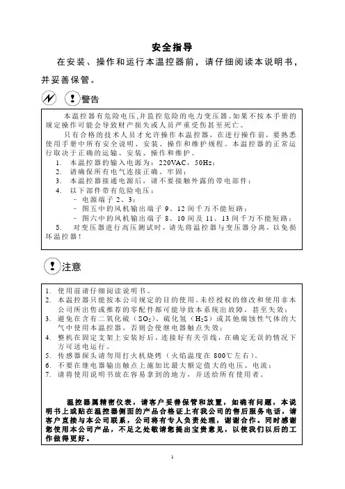
为了您的人身安全及设备的正常运行,请注意以下事项:1、使用前请仔细阅读随机资料,并按要求正确操作。
2、请勿带电维修及更换元件。
3、请使用合格的测试设备对本装置进行测试、试验。
4、如有疑问,请及时与本公司售后服务部联系。
二、主要技术参数1、额定工作电源电压:三相AC380V50HZ2、额定控制电源电压:AC220V50HZ3、防护等级:IP54三、控制系统特点1、控制箱采用1.5mm不锈钢精加工而成,简洁大方。
顶部采用坡面三角形结构,可有效应用于室外工况。
2、箱内装有一台双路温度控制器,当温度为0℃时,将自动加热。
当温度达到5℃以上时,则加热停止。
当温度达到35℃时将启动降温风扇,温度降到30℃以下后,风扇关闭,这样就保证箱内温度保持在一个安全范围内。
3、控制箱接入二路独立、互为备用的主电源,当电源I发生故障时,则自地址:山东省莱芜高新技术产业开发区凤凰路009号邮编:271100动切除电源I、投入电源II,当电源II发生故障时,则自动切除电源II、自动投入电源I,并发出报警信号,同时将故障信号发送到主控室。

僅適用於家庭使用。
For Household Use Only .Living Fan優美扇RLF-9KITUSER MANUAL使用說明書• 使用前請詳細閱讀本說明書,並保存以便日後參考。
• 本說明書中所有的圖片僅供解釋用途。
• Please read this user manual before using the product and retain it for future reference. •All the pictures in this manual are for reference only.不遵循或忽視這些安全注意事項會導致火災、觸電或個人傷害。
-請確保電力規格,必須符合本產品的電源要求。
(220-240V~50-60Hz)-切勿將本產品放在電源插座下。
-為減少觸電的潛在危險,請將插頭插在正確的電源插座上。
-本產品只適合在家居室內使用。
-此設備可供8歲以上兒童,肢體、感官、心智殘缺或缺乏經驗和知識的人使用,但他們必須已獲得監督和安全使用該設備的指導,並且了解其中的危害。
兒童不應將本產品用於玩耍。
清潔和保養,不得讓兒童在沒有監督的情況下實施。
-本設備是不打算供與(包括兒童)身體,感官或智力有障礙,或缺乏經驗和知識人士使用,除非他們是在負責他們安全的人員監督或有關使用該設備的指示下使用。
兒童應當受到監督以確保他們不會玩耍本產品,請勿讓兒童爬上風扇。
-切勿過度擰捏,彎曲或扭轉電源線,否則線芯可能會曝露在外或折斷。
拔掉電源線插頭時須緊握,切勿拉扯電線,否則會導致電源線受損、漏電等危險。
若電源線有損壞時,為避免發生危險,必須交由信興電器服務中心有限公司進行更換。
-請找出電源線,避免把本產品或將其他物件壓在電源線上面。
切勿將地毯、衣物或類似物件覆蓋在電源線上面。
請把電源線遠離容易被絆倒的地方。
-請定期清除電源插頭上之灰塵及確保電源插頭完全插入插座,否則可能會導致漏電的危險。
-手濕時切勿接觸電源插頭,否則可能引起觸電和短路。
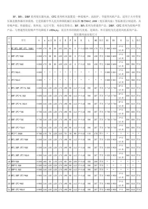
BF、BF2、DBF系列变压器风扇、CFZ系列吹风装置是一种低噪声、高防护、节能型风机产品,适用于大中型变压器及散热器冷却系统,它是依据中华人民共和国机械行业标准JB/T9642-1999(变压器风扇)等标准设计制造的,具有噪声低、性能稳定、效率高、运行可靠、寿命长等特点。
BF、BF2系列为普通型产品,DBF、CFZ系列为低噪声型产品,与普通型比较噪声平均降低5-10Db(A),而且外形结构轻巧美观,是国内、外目前较为先进的风机系列产品。
产品名称:CFZ5-12Q24型直径达ф1200的变压器吹风装置(片散1. 产品概述CFZ系列吹风装置,是一种低噪声节能型产品,专用于大中型变压器的散热器冷却系统。
它是依据中华人民共和国专业标准ZBK22002-88《变压器冷却风扇用三相异步电动机技术条件》、JB/T9642-1999《变压器风扇》与企业标准Q/CED03-2000《CFZ系列吹风装置》等标准设计制造的,具有噪声低,性能稳定,效率高,运行可靠,寿命长等特点,尤其是CFZ4、CFZ5系列系列新产品,不仅上述指标高,而且还具有结构轻巧美观,高可靠性等特点,CFZ4、CFZ5系列吹风装置是目前国内较为先进的低噪声变压器散热冷却专用吹风装置。
吹风装置配套风扇选用的是DBF系列低噪声变压器风扇,电机采用“九五”国家级科技成果推广项目异步电动机多目标优化设计软件系统设计的专用电机,叶轮采用低噪声叶型,有铆接叶轮,动叶可调压铸铝叶轮和翼形一体叶轮,采用了多项防护和低噪声专利技术,采用进口低噪声轴承,防护分级IP55,适用于户外使用。
,该系列产品规格品种齐全,覆盖φ350~φ1200风扇直径,流量3100m3/h~18500 m3/h,全压30Pa~230Pa,噪声50dB (A)~75 dB(A)各种规格产品,广泛适用于变压器散热器、冷却器的配套使用。
BFK系列变压器风扇是我公司根据用户的需求开发设计的系列变压器风扇。
树脂绝缘干式变压器使用说明书有限公司Epoxy Resin insulation dry-type transformerInstructionCo.Ltd1.适用范围2.产品特点及作用场所3.使用条件4.产品运输5.产品装卸6.检查验收7.产品安装8.运行前的检查9.试运行10. 变压器的维护和保养11. 安全注意事项Content1. Usage scope2. Character & Application3. Usage requirement4. Product Transportation5. Product load & discharge6. Inspection before receive7. Product install8. Inspection before operation9. Test operation10. Repair and Maintain11. Safety Notice1.适用范围本说明书适用于我公司生产的SC9、SCB9、SC10、SCB10、SCR9系列额定容量为6300KVA及以下,电压等级为35KV及以下的有载和无载调压树脂绝缘干式电力变压器的装卸、运输、仓储保管、安装、使用及维护等。
2.产品特点及使用场所我公司生产的环氧树脂浇注干式变压器引进国外先进技术,我公司通过反复的生产实践及频繁的理化试验成功解决了这一尖端难题,产品技术性能指标完全符合国家标准GB1094.1~2-1996、GB6450-86,技术参数符合GB/T10228-1997 标准。
该产品具有以下特点:2.1减少了包封层树脂厚度,增强了线圈的散热能力。
2.2线圈采用玻璃纤维增强网格板加强、增强了线圈的机械强度;提高了产品抗突发短路能力,线圈永不开裂;2.3线圈采用真空浇注工艺、极大地减少了线圈局部放电量,提高了线圈电气强度;2.4防爆过载能力高,冷热冲击稳定性好,噪声低;2.5带温控和风冷却装置,三相温度同屏显示,自动启停风机、故障报警、超温报警、超温跳闸以及黑匝子功能,并通过RS485串行通讯接与计算机连接,运行集中监视及控制;由于我公司树脂浇注干式变压器具有以上特点,因此该系列产品广泛应用于输变电系统,如宾馆饭店、机场,高层建筑、商业中心、住宅小区等重要场所,以及地铁、冶炼、电厂、轮船、海洋钻井平台等环境恶劣场所。
一产品概述本仪器是我公司为新式风冷干式变压器而设计的新一代电脑温度控制器,它采用美国生产的单片计算机为控制核心,结合最先进的数据存贮技术设计而成,从而使整个产品的性能迈上了一个新台阶。
和传统的模拟与数字电路组成的温度控制器相比,本仪器因采用高性能的微电脑控制器,使所需电子元器件的数量减少一半以上,从而使本仪器的电路设计和结构设计大大简化,这样就极大提高了本仪器的运行可靠性。
我公司生产的电脑温度控制器,温度设定只需通过面板上的几个按键的设置就可实现,而且设定的参数在停电后永不丢失。
本仪器还具有“黑匣子”功能,可记录变压器掉电时刻的三个线包绕组的温度。
在抗干扰方面,本仪器在设计上采用硬件和软件相结合的抗干扰措施,共同监视温控器的工作,从而达到了极强的抗干扰能力。
在使用方面,本仪器还具有操作简单、安装方便、维护容易的特点。
本产品符合JB/T7631-1994《变压器用电阻温度计》标准本产品生产体系通过ISO9002质量体系认证。
本产品被国家科委和国家经贸委评审为1997年度国家重点新产品。
二产品型号BWD-3K系列电脑温控仪产品型号及其功能如下表:三技术参数1 测温范围:0℃-200℃2 测温精度:0.5%FS±1个字3 分辨率:0.1℃4 工作电压:AC170V~AC250V( 50Hz )5 功耗:5VA6 传感器:三支Pt100铂热电阻7继电器触点容量:10A/250VAC8仪表重量:<1Kg9仪表外形尺寸:80×160×145四产品功能介绍1 具有三相线包温度的巡回显示和最高相温度显示切换功能。
2 可根据设定的开风机温度和关风机温度自动控制风机的开启和关闭,保证干式变压器在正常温度下安全的工作。
当三相线包温度中的最高一相温度超过开风机的设定温度或在手动开风机的情况下,风机会开启,同时面板上“风机”指示灯会亮。
3 具有超温报警功能。
当三相线包温度中的最高一相温度超温时,温控器会发出蜂鸣报警、面板上“超温”灯亮,并通过后板“报警”输出端(6、7端)输出开关信号给远距离的控制柜控制声、光报警。
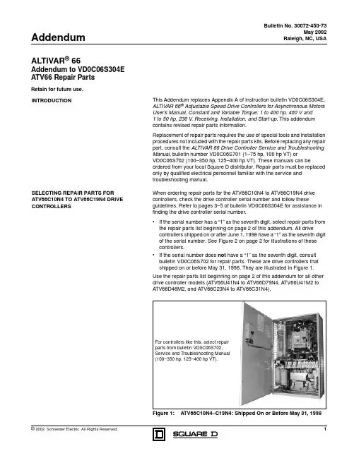
Bulletin No. 30072-450-73May 2002Raleigh, NC, USAALTIVAR ® 66Addendum to VD0C06S304E ATV66 Repair PartsAddendumRetain for future use.This Addendum replaces Appendix A of instruction bulletin VD0C06S304E, ALTIVAR 66® Adjustable Speed Drive Controllers for Asynchronous Motors User’s Manual, Constant and Variable T orque: 1 to 400 hp, 460 V and 1 to 50 hp, 230 V , Receiving, Installation, and Start-up . This addendum contains revised repair parts information.Replacement of repair parts requires the use of special tools and installation procedures not included with the repair parts kits. Before replacing any repair part, consult the ALTIVAR 66 Drive Controller Service and Troubleshooting Manual , bulletin number VD0C06S701 (1–75 hp, 100 hp VT) orVD0C06S702 (100–350 hp, 125–400 hp VT). These manuals can beordered from your local Square D distributor. Repair parts must be replaced only by qualified electrical personnel familiar with the service and troubleshooting manual.When ordering repair parts for the A TV66C10N4 to A TV66C19N4 drive controllers, check the drive controller serial number and follow theseguidelines. Refer to pages 3–5 of bulletin VD0C06S304E for assistance in finding the drive controller serial number.•If the serial number has a “1” as the seventh digit, select repair parts from the repair parts list beginning on page 2 of this addendum. All drivecontrollers shipped on or after June 1, 1998 have a “1” as the seventh digit of the serial number. See Figure 2 on page 2 for illustrations of these controllers. •If the serial number does not have a “1” as the seventh digit, consult bulletin VD0C06S702 for repair parts. These are drive controllers that shipped on or before May 31, 1998. They are illustrated in Figure e the repair parts list beginning on page 2 of this addendum for all other drive controller models (A TV66U41N4 to A TV66D79N4, A TV66U41M2 to A TV66D46M2, and A TV66C23N4 to A TV66C31N4).Figure 1:ATV66C10N4–C19N4: Shipped On or Before May 31, 1998INTRODUCTIONSELECTING REPAIR PARTS FOR ATV66C10N4 TO ATV66C19N4 DRIVECONTROLLERSFor controllers like this, select repair parts from bulletin VD0C06S702, Service and Troubleshooting Manual (100–350 hp, 125–400 hp VT).Addendum to VD0C06S304E Bulletin No. 30072-450-73ATV66 Repair Parts May 2002Figure 2:ATV66C10N4–C19N4: Shipped On or After June 1, 1998For controllers like these, select repair parts from the following Repair Parts List.Repair Parts ListDescriptionDrive Controller Part No.NoteALTIVAR 66 Adjustable Speed Drive Controllers Service and Troubleshooting ManualATV66 1–75 hp,100 hp VT VD0C06S701ATV66 100 hp CT, 125–400 hpVD0C06S702Control Kit — 460 VATV66U41N4 to D79N4ATV66C10N4 to C31N4VX4A66CK1VX4A66CK2Matched keypad display and control basket with latest firmwareControl Kit — 208/230 VATV66U41M2 to D46M2 (except ATV66D23M2S264U)VX4A66CK1 ATV66D23M2S264UVX4A66CK1S260Keypad DisplayRefer to the section “Identifying the FirmwareVersion” in Chapter 4 of bulletin VD0C06S304E and determine the firmware version of your drive controller.For drive controllers with firmware level 3.0 andlaterATV66 all sizesVW3A66206UFor drive controllers with firmware version earlier than 3.0Order the control kit listed above that is appropriate for your drive controller.Removable Control Terminal StripsATV66 all sizesVZ3N006J1, J12, and J13 on control basketBulletin No. 30072-450-73Addendum to VD0C06S304EMay 2002ATV66 Repair PartsPower Board — 460 VATV66U41N4VX5A66U41N4Includes IGBT block, rectifier diode, heatsink, and fan ATV66U54N4VX5A66U54N4ATV66U72N4VX5A66U72N4ATV66U90N4VX5A66U90N4ATV66D12N4VX5A66D12N4ATV66D16N4VX5A66D16N4Power board onlyATV66D23N4VX5A66D23N4ATV66D33N4VX5A66D33N4ATV66D46N4VX5A66D46N4ATV66D54N4VX5A66D54N4ATV66D64N4VX5A66D64N4ATV66D79N4VX5A66D79N4ATV66C10N4 VX5A661C10N4ATV66C13N4VX5A661C13N4ATV66C15N4VX5A661C15N4ATV66C19N4 VX5A661C19N4ATV66C23N4VX5A661C23N4ATV66C28N4VX5A661C28N4ATV66C31N4VX5A661C31N4Power Board — 208/230 VATV66U41M2VX5A662U41M2Includes IGBT block and rectifier diode ATV66U72M2VX5A662U72M2ATV66U90M2VX5A662U90M2ATV66D12M2VX5A66D12M2Power board onlyATV66D16M2VX5A66D16M2Power Board and Gate Driver Board — 208/230 VATV66D23M2VX5A66D234M2Matched set ATV66D33M2VX5A66D335M2ATV66D46M2VX5A66D466M2Gate Driver Board — 460 VATV66D16N4VX5A66103Gate driver board only ATV66D23N4VX5A66104ATV66D33N4VX5A66105ATV66D46N4VX5A66106ATV66D54N4VX5A66107ATV66D64N4VX5A66108ATV66D79N4VX5A66109Gate Driver Board — 208/230 V ATV66D12M2VX5A66112ATV66D16M2VX5A66113Inverter IGBT — 460 V[1] For units with a serial number starting with “6W”, or for units with a serial number starting with “86” and a date code of 0216 or earlier. [2]For units with a serial number starting with “86”and a date code of 0217 or later.Refer to pages 3–5 of bulletin VD0C06S304E for assistance in finding the serial number and date code.ATV66D16N4VZ3lM2050M1201 1 dual IGBT block ATV66D23N4VZ3lM2075M1201ATV66D33N4VZ3lM2100M1201ATV66D46N4, D54N4VZ3lM2150M1201ATV66D64N4VZ3lM2200M1201ATV66D79N4 [1]VZ3IM2300M1201ATV66D79N4 [2]VZ3IM2200M1202ATV66C10N4VZ3IM2300M1202 2 IGBT blocks, 2 snubber boards, 2 gate driver boards, 1 clamp moduleATV66C13N4 to C19N4VZ3IM2400M1202ATV66C23N4, C28N4VZ3IM1400M1207 4 IGBT blocks, 2 snubber boards, 2 gate driver boards ATV66C31N4VZ3IM1500M1207Repair Parts List (Continued)DescriptionDrive Controller Part No.NoteAddendum to VD0C06S304E Bulletin No. 30072-450-73ATV66 Repair Parts May 2002Inverter IGBT — 208/230 VATV66D12M2VZ3IM2075M0601 1 dual IGBT blockATV66D16M2VZ3IM2100M0601ATV66D23M2VZ3IM2150M0601ATV66D33M2VZ3IM2200M0601ATV66D46M2VZ3IM2300M0601Inverter IGBT Clamp Capacitor ATV66C23N4 to C31N4VY1ADC610 1 capacitorDynamic Braking IGBT — 460 VATV66D16N4, D23N4VZ3IM1025M1001 1 IGBT BlockATV66D33N4, D46N4VZ3IM2050M1201ATV66D54N4VZ3IM2100M1201ATV66D64N4, D79N4VZ3IM2150M1201ATV66C10N4 to C19N4VZ3IM1300M1202 1 IGBT block, 1 diode block,1 snubber board, 1 gate driver board ATV66C23N4VZ3IM1400M1208ATV66C28N4, C31N4VZ3IM1300M1208 2 IGBT blocks, 2 diode blocks,2 snubber boards, 1 gate driver boardDynamic Braking IGBT — 208/230 VATV66D12M2, D16M2VZ3IM1060M0601 1 IGBT blockATV66D23M2VZ3IM2075M0601ATV66D33M2VZ3IM2100M0601ATV66D46M2VZ3IM2150M0601Dynamic Braking Clamp Capacitor ATV66C10N4 to C19N4VY1ADC616 1 capacitorATV66C23N4 to C31N4VY1ADC614Line Filter Board — 460 VATV66D16N4, D23N4VX4A66103Board onlyATV66D33N4, D46N4VX4A66104ATV66D54N4 to D79N4VX4A66105ATV66C10N4 to C31N4VX4A66106Assembly with board and capacitors Line Filter Board — 208/230 VATV66D12M2, D16M2VX4A66103Board onlyATV66D23M2, D33M2VX4A66104ATV66D46M2VX4A66105Line Rectifier Diode — 460 VATV66D16N4, D23N4VZ3DM6075M16016-pack diode block ATV66D33N4VZ3DM2080M1606 1 dual diode block ATV66D46N4VZ3DM2100M1601ATV66D54N4 to D79N4VZ3DM2160M1606ATV66C10N4, C13N4VZ3DM2170M1602ATV66C15N4VZ3DM2260M1602ATV66C19N4VZ3DM2350M1602ATV66C23N4 to C31N4VZ3DM2600M1602Line Rectifier Diode — 208/230 VATV66D12M2, D16M2VZ3DM6075M16016-pack diode block ATV66D23M2VZ3DM2080M16061 dual diode block ATV66D33M2VZ3DM2100M1601ATV66D46M2VZ3DM2160M1606DC Bus Capacitor—460 VATV66D16N4, D23N4VY1ADC152V450 1 capacitorATV66D33N4, D46N4VY1ADC472V450ATV66D54N4VY1ADC605Assembly with capacitors and stirring fan ATV66D64N4, D79N4VY1ADC606ATV66C10N4 to C19N4VY1ADC615Assembly with capacitors ATV66C23N4 to C31N4VY1ADC608DC Bus Capacitor—208/230 VATV66D12M2, D16M2VY1ADC152V450 1 capacitorATV66D23M2, D33M2VY1ADC472V450ATV66D46M2VY1ADC605Assembly with capacitors and stirring fanRepair Parts List (Continued)DescriptionDrive Controller Part No.NoteBulletin No. 30072-450-73Addendum to VD0C06S304EMay 2002ATV66 Repair PartsDC Bus Capacitor Bank Plexiglass Shield ATV66C10N4 to C19N4VY1ADV611Shield with mounting screws Discharge Resistor — 460 VATV66D33N4 to D79N4VZ3R5K0W040 1 resistor ATV66C10N4 to C19N4VZ3R2K5W600 2 resistorsATV66C23N4 to C31N4VZ3R1K2W480 1 resistorDischarge Resistor — 208/230 V ATV66D23M2 to D46M2VZ3R5K0W040Precharge Resistor — 460 VATV66D16N4, D23N4VZ3R033W009ATV66D33N4, D46N4VZ3R010W025ATV66D54N4 to D79N4VZ3R010W481ATV66C10N4 to C31N4VZ3R010W270 2 resistors Precharge Resistor — 208/230 VATV66D12M2, D16M2VZ3R033J710 1 resistorATV66D23M2, D33M2VZ3R010W025ATV66D46M2VZ3R010W481Precharge Contactor — 460 VATV66D16N4, D23N4LP4D1801BW3 1 contactorATV66D33N4LC1D1801P7ATV66D46N4LC1D2501P7ATV66D54N4, D64N4LC1D4011P7ATV66D79N4LC1D6511P7ATV66C10N4, C13N4VY1A661C1010ATV66C15N4, C19N4VY1A661C1510ATV66C23N4 to C31N4VY1A661C2310Precharge Contactor — 208/230 VATV66D12M2, D16M2LP4D2500BW3ATV66D23M2LC1D3201P7ATV66D33M2LC1D5011P7ATV66D46M2LC1D4011P7Precharge Contactor Auxiliary Contact Block ATV66C10N4 to C31N4LA1DN04 1 contact blockPrecharge Circuit Protector ATV66C10N4 to C31N4GV2M10Heatsink Fan — 460 VATV66U41N4, U54N4VZ3V661Fan(s) and mounting bracketATV66U72N4VZ3V662ATV66U90N4, D12N4VZ3V663ATV66D16N4, D23N4VZ3V664ATV66D33N4 to D79N4VZ3V665 1 fanATV66C10N4 to C19N4VZ3V670Fan assembly and capacitor ATV66C23N4 to C31N4VZ3V666 1 fan and capacitorHeatsink Fan — 208/230 VATV66U41M2VZ3V662Fan(s) and mounting bracket ATV66U72M2, U90M2VZ3V663ATV66D12M2, D16M2VZ3V664ATV66D23M2 to D46M2VZ3V665 1 fanStirring Fan — 460 VATV66D33N4 to D79N4VZ3V6654Power board fan ATV66D54N4 to D79N4VZ3V6655Capacitor bank fan ATV66C10N4 to C19N4VZ3V671Power board fan ATV66C23N4 to C31N4VZ3V669IGBT fan Stirring Fan — 208/230 V ATV66D23M2 to D46M2VZ3V6654Power board fan ATV66D46M2VZ3V6655Capacitor bank fanFan Failure Detection Assembly ATV66C23N4 to C31N4VY1ADR100Resistor and temperature switch Fan Failure Relay AssemblyATV66C23N4 to C31N4VZ3SA66012Relay and retaining clip Power Supply for Overtemperature Detection CircuitATV66C23N4 to C31N4VY1A66200Power supply only Heatsink T emperature SensorATV66C10N4 to C31N4VZ3GN005NTC thermistor and cableRepair Parts List (Continued)DescriptionDrive Controller Part No.NoteAddendum to VD0C06S304E Bulletin No. 30072-450-73ATV66 Repair Parts May 2002T emperature SwitchATV66C10N4 to C19N4VZ3G007 1 switch—mounted on fuse bar ATV66C10N4 to C19N4VZ3G008 2 switches—mounted on heatsink and motor current sensorATV66C23N4 to C31N4VZ3G004 1 68 °C switch and 1 85 °C switch, heatsink mounted Motor Current Sensor — 460 VATV66D33N4, D46N4VY1A66104 2 sensorsATV66D54N4 to D79N4VY1A66105ATV66C10N4, C13N4VY1A66106 1 sensor ATV66C15N4, C19N4VY1A66107ATV66C23N4 to C31N4VY1A66108Motor Current Sensor — 208/230 VATV66D23M2VY1A66104 2 sensors ATV66D33M2, D46M2VY1A66105Ground Fault Sensor—460 V ATV66C10N4 to C19N4VY1A66109 1 sensor ATV66C23N4 to C31N4VY1A66110Control Power Transformer — 460 VATV66D33N4 to D79N4VY1ADA604T ransformer only ATV66C10N4 to C19N4VY1ADA606ATV66C23N4 to C31N4VY1ADA607Control Power Transformer — 230 V ATV66D23M2 to D46M2VY1ADA614Control Power Fuses ATV66C10N4 to C31N4DF3CF00501 2 fuses, F5 and F6DC Bus FuseATV66C10N4, C13N4VY1ADF250V700 1 fuseATV66C15N4, C19N4VY1ADF350V700ATV66C23N4 to C31N4VY1ADF400V700AC Line FuseATV66C23N4VY1ALF700V700ATV66C28N4VY1ALF800V700ATV66C31N4VY1ALF900V700Power T erminal Blocks — 460 VATV66D16N4, D23N4VZ3N603All output terminals and DIN rail for mounting ATV66D33N4, D46N4VZ3N604ATV66D54N4 to D79N4VZ3N605Power T erminal Blocks — 208/230 VATV66D12M2, D16M2VZ3N603ATV66D23M2, D33M2VZ3N604ATV66D46M2VZ3N605Box Lug Power T erminalATV66C10N4 to C19N4VZ3N008Three terminals for replacing power or ground terminalsA TV66C10N4–C13N4: L1, L2, L3, T1, T2, T3, +, –, GNDA TV66C15N4–C19N4: T1, T2, T3, +, –, GNDClam Shell Power T erminal ATV66C15N4 to C19N4VZ3N009Three terminals for replacing power terminals L1, L2, L3Power T erminal Plexiglass Shield ATV66C10N4 to C19N4VY1ADV612Dynamic Braking Flexible Bus ATV66C23N4 to C31N4VZ3N626Connects capacitor bank to PA terminal and DB IGBT moduleFlex Cables — 460 V(Control Board J3, J4, and J5)ATV66U41N4 to D12N4VZ3N601 3 flat ribbon cablesATV66D16N4, D23N4VZ3N613ATV66D33N4 to D79N4VZ3N615ATV66C10N4 to C31N4VZ3N616Flex Cables — 208/230 V (Control Board J3, J4, and J5)ATV66U41M2 to U90M2VZ3N601ATV66D12M2, D16M2VZ3N613ATV66D23M2 to D46M2VZ3N615Repair Parts List (Continued)Description Drive Controller Part No.NoteBulletin No. 30072-450-73Addendum to VD0C06S304EMay 2002ATV66 Repair PartsInternal Hardware Kit — 460 VATV66U41N4 to U72N4VY1ADV601Specialty hardware, mounting posts, etc.ATV66U90N4, D12N4VY1ADV602ATV66D16N4, D23N4VY1ADV603ATV66D33N4, D46N4VY1ADV604ATV66D54N4 to D79N4VY1ADV605ATV66C10N4 to C19N4VY1ADV613ATV66C23N4 to C31N4VY1ADV614Internal Hardware Kit — 230 VATV66U41M2VY1ADV601ATV66U72M2, U90M2VY1ADV602ATV66D12M2, D16M2VY1ADV603ATV66D23M2, D33M2VY1ADV604ATV66D46M2VY1ADV605Packaging Kits — 208/230/460 V(Order this kit if the control basket is not mounted to a white metallic ground plane within the drivecontroller)ATV66U41N4 to U72N4VY1A66101All plastic sides, covers, and front door ATV66U90N4, D12N4VY1A66102ATV66D16N4, D23N4VY1A66103ATV66U41M2VY1A66101ATV66U72M2, U90M2VY1A66102ATV66D12M2, D16M2VY1A66103Packaging Kits — 208/230/460 V(Order this kit if the control basket is mounted to a white metallic ground plane within the drivecontroller)ATV66U41N4 to U72N4VY1A66111ATV66U90N4, D12N4VY1A66112ATV66D16N4, D23N4VY1A66113ATV66U41M2VY1A66111ATV66U72M2, U90M2VY1A66112ATV66D12M2, D16M2VY1A66113Clip Pliers(T ool for removing voltage regulator heatsink clips)ATV66U41N4 to D23N4VY1ADV608Use when replacing power board, all IGBTs, filter board, precharge components, bus capacitors, and line rectifier diodes.ATV66U41M2 to D16M2Repair Parts List (Continued)DescriptionDrive Controller Part No.NoteElectrical equipment should be serviced only by qualified personnel. No responsibility is assumed by Schneider Electric for any consequences arising out of the use of this material. This document is not intended as an instruction manual for untrained persons.ALTIVAR ® 66 Addendum to VD0C06S304E ATV66 Repair Parts Bulletin No. 30072-450-73Instruction Bulletin May 2002Square D Company 8001 Hwy 64 East Knightdale, NC 275451-888-SquareD (1-888-778-2733)。

ZH-BFKM24/8QJ型变压器风冷智能控制柜操作说明书保定中恒电气有限公司BaoDing ZhongHeng Electric CO.,LTDZH-BFKM24/8QJ 型变压器风冷智能控制柜操作说明书1目 录一、型号说明 ∙∙∙∙∙∙∙∙∙∙∙∙∙∙∙∙∙∙∙∙∙∙∙∙∙∙∙∙∙∙∙∙∙∙∙∙∙∙∙∙∙∙∙∙∙∙∙∙∙∙∙∙∙∙∙∙∙∙∙∙∙∙∙∙∙∙∙∙∙∙∙∙∙∙∙∙∙∙∙∙∙∙∙∙∙∙∙∙∙∙∙∙∙∙∙∙ 2二、使用条件 ∙∙∙∙∙∙∙∙∙∙∙∙∙∙∙∙∙∙∙∙∙∙∙∙∙∙∙∙∙∙∙∙∙∙∙∙∙∙∙∙∙∙∙∙∙∙∙∙∙∙∙∙∙∙∙∙∙∙∙∙∙∙∙∙∙∙∙∙∙∙∙∙∙∙∙∙∙∙∙∙∙∙∙∙∙∙∙∙∙∙∙∙∙∙∙∙ 2三、技术参数 ∙∙∙∙∙∙∙∙∙∙∙∙∙∙∙∙∙∙∙∙∙∙∙∙∙∙∙∙∙∙∙∙∙∙∙∙∙∙∙∙∙∙∙∙∙∙∙∙∙∙∙∙∙∙∙∙∙∙∙∙∙∙∙∙∙∙∙∙∙∙∙∙∙∙∙∙∙∙∙∙∙∙∙∙∙∙∙∙∙∙∙∙∙∙∙∙ 3四、功能特点 ∙∙∙∙∙∙∙∙∙∙∙∙∙∙∙∙∙∙∙∙∙∙∙∙∙∙∙∙∙∙∙∙∙∙∙∙∙∙∙∙∙∙∙∙∙∙∙∙∙∙∙∙∙∙∙∙∙∙∙∙∙∙∙∙∙∙∙∙∙∙∙∙∙∙∙∙∙∙∙∙∙∙∙∙∙∙∙∙∙∙∙∙∙∙∙∙ 3五、控制操作程序∙∙∙∙∙∙∙∙∙∙∙∙∙∙∙∙∙∙∙∙∙∙∙∙∙∙∙∙∙∙∙∙∙∙∙∙∙∙∙∙∙∙∙∙∙∙∙∙∙∙∙∙∙∙∙∙∙∙∙∙∙∙∙∙∙∙∙∙∙∙∙∙∙∙∙∙∙∙∙∙∙∙∙∙∙∙∙∙∙∙ 4六、故障报警及冗余控制程序∙∙∙∙∙∙∙∙∙∙∙∙∙∙∙∙∙∙∙∙∙∙∙∙∙∙∙∙∙∙∙∙∙∙∙∙∙∙∙∙∙∙∙∙∙∙∙∙∙∙∙∙∙∙∙∙∙∙∙∙∙∙∙∙∙∙∙∙∙∙ 6七、检修操作注意事项∙∙∙∙∙∙∙∙∙∙∙∙∙∙∙∙∙∙∙∙∙∙∙∙∙∙∙∙∙∙∙∙∙∙∙∙∙∙∙∙∙∙∙∙∙∙∙∙∙∙∙∙∙∙∙∙∙∙∙∙∙∙∙∙∙∙∙∙∙∙∙∙∙∙∙∙∙∙∙∙∙∙ 9 附录:触摸屏的操作说明∙∙∙∙∙∙∙∙∙∙∙∙∙∙∙∙∙∙∙∙∙∙∙∙∙∙∙∙∙∙∙∙∙∙∙∙∙∙∙∙∙∙∙∙∙∙∙∙∙∙∙∙∙∙∙∙∙∙∙∙∙∙∙∙∙∙∙∙∙∙∙∙∙∙∙∙∙∙10注:在使用风冷控制柜前,检修操作注意事项一定要认真阅读!ZH-BFKM24/8QJ 型变压器风冷智能控制柜操作说明书2一、型号说明二、使用条件2.1 户外、户内使用;2.2 海拔高度:2000米以下;2.3 环境温度:-40℃~+55℃;2.4 最大日温差:≤ 25K ;2.5 日照强度:≤0.1W/cm 2;2.6 相对湿度:≤ 95%RH ;2.7 大气压力:80~110kPa ;2.8 最大风速:≤ 35m/S ;2.9 地震烈度:水平加速度≤ 0.3g ,垂直加速度≤ 0.15g ;2.10 污秽等级:III 级(2.8kV/cm );2.11 覆冰厚度:≤10mm ;2.12 超越上述使用条件的地区,定制产品时要额外声明。
TransformersAdvancing a sustainable energy future for allThe journey continues with the world’s largest installed baseWindstar transformerFor large offshore wind turbineSubsea transformerFor depths up to 3,000 metersHVDC transformerWorld’s most powerful1,100 kilovolt (kV) transformerSmart transformersEnabling your digital future130 years of groundbreaking solutionsToday wherever you are a transformer is powering you−Transformers are fundamental to electricalnetworks, they enable efficient and safe power transmission and consumption−With increasing complexity in the grid,transformers are also increasingly used for improving power quality and network managementTransmission and distributionMetals & Mining, Oil & GasIndustry MobilityCommercial and InfrastructurePower generationAbout Transformers Business~14,000 employeesRevenues in ~ 90countries ~ 60Facilities around the worldWith ~ 30 servicecentersComplete rangeof power anddistributiontransformers,componentsand services Voltage rangeup to 1,200 kV ACand 1,100 kV DCAbout Transformers Business -World’s largest installed baseDistribution transformersDry transformersPower transformersTraction transformers>325,000>75,000>2,000,000>30,000Reactors>4,000HVDC transformers>700Complete range of Transformers, Components and ServiceDigitalization of transformers: TXpert EcosystemOnline and standalone intelligenceOpen and scalableDistributionTransformersPower TransformersHVDC ConverterTransformersDry TransformersTraction TransformersIndustry & special applicationsTransformers Insulation, components &digital sensorsTransformerServicePower Transformers –Production UnitsUSACrystal SpringsItaly MonseliceFinland Vaasa Colombia PereiraTurkeyIstanbul (Kartal)Vietnam HanoiChina ZhongshanPoland LodzGermany Bad Honnef Thailand BangkokUSASouth BostonIndia VadodaraCanada Varennes China ChongqingSpain CordobaSweden LudvikaBrazil GuarulhosDistribution Transformers –Production UnitsDry FactoriesLiquid-filled DTR factories Traction FactoriesDTR + DRY LocationsColombiaPereiraBrazilBlumenauUSASpainGermanyPolandSwitzerlandTurkeyIstambul(Dudullu)EgyptCairoSouthKoreaChinaIndiaVadodaraSouthAfricaJohannesburgVietnamHanoiRussiaKhotkovo(Moscow)CanadaQuebec CityDatongCheonanSecheronTrasforZaragozaJeff CitySouth BostonShanghaiHefeiLodzBrilonBlandTransformer Service UnitsAmericasBrazil, Canada, Chile, Colombia, Mexico, Panama, Peru, USA EuropeFinland, France, Germany, Italy, Norway, Poland,Spain, Sweden, Switzerland, Turkey, UKAsia, Middle East, AfricaAustralia, China, India, Qatar, UAESaudi Arabia, Singapore, South Africa, ThailandNew forces are driving the change in today and future transformer design RenewablesEnergy efficiency Safety and Environment Service and Intelligence Ex: Low-loss transformersEx: TCO calculatorEx: Voltage regulatorsEx: Booster transformersEx: 66 kV specialty transformerEx: Natural Ester oilEx: Dry-type transformers, reactors and bushingsEx: CoreSense familyEx: CoreTec™EX: TXpert™02 03 01 0405 06Security andResilienceNew boundariesEx: AssetShield™ballistic protection systemEx: Dry bushing (O Plus Dry)Ex: TXtreme™Ex: 1,100 kV converter transformerEx: Effilight® traction transformerEx. Dry transformers up to 72.5 kV–Maximizing financial savings–Reducing CO2 emissions–Integrating more green energy into the grid–Superior engineering and design for grid complexity–Insulating fluids and materials–Oil to dry conversion of transformers and components–Condition-based maintenance–On-line monitoring–Multiple intelligent electronic devices–Onsite vulnerability assessment, hardening, monitoring,rapid repair, rapid replacement–UHV AC-DC transformers–Submersible solutions–Low noiseTransformers —Key Customers SegmentsDatacenters−Reliable partner for global Datacenter customers −Ensuring world class the stability and reliabilityRenewables−Integrating more green energy into the grid −Superior engineering and design for grid complexityUtilities−Partner of choice for utilities with a long-history −Product and Service offering to serve the most complex customer requirementsIndustries−Long-term collaboration e.g. O&G, Pulp and Paper globally −Global network to provide offering worldwideTransportation−Worlds largest traction transformers manufacturer −Wide transformers offering for Marine industry0203010504VariousC O M P O N E N T STXpert TM Ecosystem Unlocking the power of the digital gridToday TomorrowPower systems of the future —an evolutionary visionIncreasing complexity of the grid will impact transformers in new ways, for example:Increasingly overloaded based on generation mixIntegration of renewables leads to reverse and dynamic power flowsDynamic load profiles and increasing risk of outagesOur rich history of leadership in transformers and digitalization2016ABB continues to innovate in digitalization, launching AssetShield ™ballistic detection and response solutions1990sFirst digitalcontrol introduced for transformers1890Jonas Wenström, a Swedish engineer from ASEA(later ABB) invented the world’s firstcommercial three-phase electric power system, including the three-phase transformer2020 and the FutureTXpert TM Ecosystem , Machine learning Artificial intelligence to maximize transformer performanceA truly interconnected smart grid emerges1980Fiber optic temperature monitoring pioneered by ABB2013Asset Health Center enterprise assetmanagement solution is introduced, today known as Ellipse®2015CoreSense ™DGA sensors provide continuous monitoring for transformer faults2017ABB launches TXpert ™the world’s first digital distributiontransformer and CoreSense ™M10 multi-gas DGA2018Launch of the TXpert TMEnabled Power Transformer sets the digitalization benchmark.TXplore ™Safe, fast and internal robotic inspection2001Transformer Electronic Control (TEC )introduced to enable condition monitoring2010Self Dehydrating Breather eSDB with digital tracking is launched2019ABB to launch TXpert ™DRY the world’s first digital dry distribution transformer and APM EDGE Station level solution.2005Remote monitoring introduced with TEC version 2TXpert TM Ecosystem —Products, Software, Services, SolutionsPower or Distribution transformer TXpert™ReadySensorsTXpert™Hub−Reduced costs and risks−Optimized operations−Extended life-cycle expectancy−Enhanced environmental performance −Full ecosystem−Digital distribution & substations−Asset performance Management−Virtual site management−Modular−Scalable−Future-proof−Manufacturer agnostic Unlocking the potential of digital gridTransforming performance The future is openDigitalization of transformers for increasing life expectancyLevels and trendsProbability of Failure (PoF)Expert systemExtend asset lifetime thanks to online monitoring and condition-based maintenanceCheck different parameters, levels and trends while comparing them to international standards like IEEE or IEC.Give maintenance recommendations based on design parameters, historical trends and on-line data.Classify each transformer by its PoFto prioritize maintenance work.Online MonitoringTransformers for a sustainable worldWe enable access to electricity with a focus on sustainabilityDecarbonizationResponsible resource utilizationSustainable infrastructurePeople andecosystems safetyWe are committed to contributing to the United Nations Sustainable Development GoalsCentralized generationEnd consumersDistributed generationFast charging 50 –350 kW3 –7 kWMV/HV MV/LVHV lineMV line LV lineIsolated 3 –350 kW10 –20 kWThe total cost of ownership tool Typical savings for a 40 MVA, 112 kV transformerReducing total costs for business and the environmentDifference between eco-efficient and traditional designsEnergy savings/year -91,542 kWhCO 2emission reduction/year -38 tonnesAs an example, the European Union alone has an estimated 4.5 million distribution transformers which could avoid 38 TWh of electrical losses and 30 million tonnes of CO 2emissions every year via energy efficient transformers.Circularity in transformersCopperAluminumSteelOil (new development)Transformers can be ~99% recyclable and reusableResponsible sourcingDesigns built with TCO(total cost of ownership)Prolonged lifetime with conditionmonitoring, life-assessment andpreventive maintenance services››››EconiQ TM transformers: co-creating sustainable solutions Your partner in the sustainability journeyacross the transformer life cycleWith transparency on environmentalimpacts using science-basedmethodologiesSolutions for decarbonization, enhancedsafety, protecting ecosystems andresponsible resource useDriving energy efficiency for reducing GHG emissionsProud to be active partner with initiatives worldwide for driving higher energy efficiency standards in transformers e.g.Partnering worldwide with other key Standardization Committees: IEEE, cigre and country organizations(European Committee for Electrotechnical Standardization)Currently holding the Secretariat for Transformers Committee CLC TC 14International Electrotechnical CommissionCurrently holding Chair of Transformers Committee IEC TC 14Providing technical expertiseto United4Efficiency Program (Under leadership of UNEP)Transformers and services —partnering with our customers for the grid of the futurePowerful transformers for bulk power transmissionAbout 800 million peopleworldwide do not haveaccess to electricity.The 3293 kilometers longChangji-Guquan link in China iscapable of transmitting 12,000megawatts, that is enough powerfor about 12 million people in Chinawith about 40% lower losses(1).Hitachi Energy 800-ton 1100 kVUHVDC transformers facilitate powerflow across this link from the sendingstation.Grid interconnections with HVDC converter transformers HVDC Light®transmission system,Norway-Germany1,400 MW, ±525 kV, 623 kilometers.TenneT in Germany and Statnettin Norway.Called “The green-link” it will enabletrade in hydro power from Norway andsolar and wind power from Germany.HVDC Converter and AC transformersfrom Hitachi Energy in both countries.Compact design for challenging transportation.GERMANY NorwayGermanyLarge scale integration of renewables with digital transformers Mainstream RenewablePower -Andes RenovablesSupporting Chile’s aim to get 70% of itselectricity from renewables by 2050.12 wind and solar projects, 1500 MWcapacity –electricity for 1.3 million people based on per capita usage in ChileTXpert TM Enabled Power Transformers for grid integration:−Designed to never go offlineunexpectedly−Enable preventive maintenance−Remote management in far-flung locationsSOUTHAMERICACHILECkani109 MWTchamma157 MWCerro Tigre 185 MWPampa Tigre100 MWLianos del Viento160 MWRio Escondido 145 MWValle Escondido105 MWSacro170 MVCuel33 MWAlena84 MWAuora129 MWPuelche Sur156 MWInterContinental Robertson Quay Hotel, Singapore−Minimize out-age risk−Maximize return on investment−Optimize operations with condition-based maintenance −Enhanced safety of personnel and environmentTXpert TMEnabled dry transformerIncrease in book value of the transformer at the end of 20 years100%Increase in the lifespan of the transformer50%Reduction in the failure rate40%It is projected thatby 2050 more thantwo-thirds of the world population will live in urban areas.75 dry transformers from Hitachi Energy are installed in the Burj Kalifa, Dubai, eliminating risks of oil spills and safety hazards.Enhancing safety with TXpand A rupture resistant transformer solution:−Capable of absorbing the expansion caused by gases generated during a 20 megajoule arc−Minimizing oil spillage and predictably channeling what little oil escapes for easy containment−Risk of unplanned and long outages are reduced−The TXpand transformer technology has been co-created with our partner Hydro Quebec, CanadaEliminating hazards of oil-spills Dry-type transformers−100% oil-free to minimize environmental contamination and fire hazardEster insulation fluid−Biodegradable as designated by the Environmental Protection Agency (EPA)−Reduced fire risk with 355˚C fire-point for natural esters as compared to 170˚C for mineral oil−Available in power and distribution transformer up to 420 kV / BIL 1425 kV −Supplied about 200 power transformers and 12,000 distribution transformers with ester fluidsEnhancing safety, reducing environmental incidents Reducing incidents withTXplore TM−No, or very little, oil needs to behandled−Eliminates the risk of a personentering confined space−Inspection can begin immediately aftertaking an outage−Significant reduction in outage timeCircularity in transformersCircularity is present already in the transformers industry; but considering that almost 99 % of the transformer materials could be reused or recycled, a lot more can be done towards circularity.A recent example is the Stena recycling and Hitachi Energy case in Sweden where old transformers will be disposed reusing or recycling about 99% of the material, comprising 64% material recycling, 35% clean, low emissions efficient incineration for energy and the balance 1% as disposed waste.The new normalVirtual Factory Acceptance Test (FAT) -Ensuring full transparency and trustCity A, Country 1 CustomerCity B, Country 2Hitachi Energy factoryInternetTest areaControl roomNo travelSaves time, effort and costsSimple and easy to useTransparentHelps in maintainingtimely deliveriesUtilizing the power of virtual technologiesAugmented reality powered visual inspection by experts 24/7−See with the eyes of our experts who will guide your hands−Check status of alarms andmonitoring devices to detect defaults−Access transformer virtualinstallation support Fast service solutions No travelGlobal specialistsLive troubleshootingCustomer at site Hitachi Energy expert。
71-4198-2506/08LionelCW-80 TransformerOwner’s Manual Cauti o n—ElECtri C t oynot rECommEndEd for ChildrEn undEr Eight yEars of agE. as with all ElECtriC produCts, prECautions should bE obsErvEd during handli n g a nd usE t o prEvEnt ElECtri C shoCk. TransfOrMer raTings—i n put:120 v aC; 60 hz only.Congratulations! C ongratulations on your purchase of the Lionel CW-80 Transformer! This device combinesa high output control unit and an internal power supply, providing your railroad with 80 watts and five amps of alternating current. With a variable accessory voltage, the CW-80 Transformer features the precision control you demand!Read this manual thoroughly before using your Transformer. It has important information on the setup and operation of this product. If you have any questions after reviewing these instructions, contact Lionel Customer Service at 586-949-4100.The following Lionel marks may be used throughout this instruction manual and are protected under law. All rights reserved.Lionel ®, TrainMaster ®, Odyssey ®, RailSounds ®, CrewTalk ™, TowerCom ™, DynaChuff ™, StationSounds ™, Pullmor ®, ElectroCoupler ™, Magne-Traction ®, CAB-1® Remote Controller, PowerMaster ®, Lionel ZW ®, ZW ®, PowerHouse ®, TMCC ®, Lionelville™, Lockon ®, Wireless Tether ™, LionMaster ®, FatBoy ™, American Flyer ®, TrainSounds ™, PowerMax ™, LEGACY ™, PowerMax ™ Plus The name FasTrack ® is used with permission from Pitsco, Inc.fCC statementWarning: Changes or modifications to this unit not expressly aproved by the party responsible for compliance could void the user authority to operate the equipment.Notes: This equipment has been tested and found to comply with the limits for a Class B digital device, pursuant to Part 15 of the FCC Rules. These limits are designed to provide reasonable protection against harmful interference in a residential installation. This equipment generates, uses and can radiate radio frequency energy and, if not installed and used in accordance with the instructions, may cause harmful interference to radio communications.However, there is not guarantee that interference will not occur in a particular installation. If this equipment does cause harmful interference to radio or television reception, which can be determined by turning the equipement off and on, the user is encouraged to trip to correct the interference by one or more of the following measures:• Reorient or relocate the receiving antenna.• Increase the separation between the equipment and receiver.• Connect the equipment into an outlet on a circuit different from that to which the receiver is connected.• Consult the dealer or an experienced radio/TV technician for help.Table of contentsOperating your CW-80 Transformer safely 4 Wiring your CW-80 Transformer 5-6 Connecting the FasTrack terminal section 7 Operating your trains with the CW-80 Transformer 8 Experiencing the features of the CW-80 Transformer 8-9 Setting the accessory output 10 Powering your layout with the CW-80 Transformer 11 Troubleshooting 11 Limited Warranty/Lionel Service 12Operating your CW-80 Transformer safelyY our Lionel CW-80 Transformer is listed by Underwriter’s Laboratory Inc. and has been carefully designed to ensure peak performance. When using electrical products, basic safety precautions should be maintained.Be sure to observe the following guidelines:• Read the manual thoroughly before using this device.• This device is not recommended for children under eight years of age.• Parents should periodically inspect this product for potential hazards and, if necessary, have them repaired by an authorized Lionel Service Center. In the event that such a condition exists, the transformer should not be used until it has been properly repaired.• The CW-80 Transformer is intended to be used indoors. Do not use this device if water is present. Serious or fatal injuries may result.• Use the CW-80 Transformer only for its intended purpose.• The CW-80 Transformer was designed to operate on 120-volt, 60-Hertz power. Do not connect this product to any other power supply.• Do not operate the CW-80 Transformer with a damaged cord, plug, or case.• To avoid the risk of electrical shock, do not disassemble the unit. There are no user serviceable parts inside. If damaged, take this product to an authorized Lionel Service Center. A list of authorized Service Centers is packed with this unit.• Do not operate the CW-80 Transformer on your layout unattended. Obstructed accessories or stalled trains may overheat, resulting in damage to your layout.• Always unplug the CW-80 Transformer from the power source when not in use.• Never insert objects into the ventilation slots on this product. Damage to sensitive electronic components can result.Wiring your CW-80 Transformerf or best performance on large layouts, it is recommended that you use 16-gauge wire toconnect your CW-80 Transformer to the track. Use the stripped ends of the wires, or spade-shaped connectors on all CW-80 Transformer connections, with no more than two wires on each terminal. Terminal strips (available at your local electronics supply store) allow you to connect multiple wires to evenly distribute power to your layout.Make sure that all connections are secure. Loose connections can produce extremely high temperatures. For this reason, do not touch the terminals or track connections during use. Also, do not locate scenery materials such as lichen or ground foam near the terminals.To prevent the excessive build up of heat, be sure to select the proper wire gaugefor your layout. Follow these guidelines:• Track connections (or Lockon connections) must be made with 18-gauge wire or heavier. Larger layouts require a minimum of 16-gauge wire.• Use 24-gauge wire only when connecting single accessories that require lower current.• When wiring multiple accessories (two or more) or accessories that require higher current, be sure to use 18- to 16-gauge wire.1. Attach a Lionel Lockon to your track.As illustrated in Figure 1, slide the bottom edge of the outside rail into the metal lip on the Lockon. Press the clip at the end of the Lockon over the bottom edge of the inside rail.Figure 1. Lockon attachmentWiring your CW-80 Transformer (continued)2. Attach one wire to the Lockon spring clip terminal labeled “1” and connectit to the power terminal labeled “A”. All Controller connections areillustrated in Figure 2.To attach the wire to the Lockon, press down on the top of the terminal clip so that a metal loop is formed. Slide the bare end of the wire into the exposed loop. Release pressure on the terminal clip, allowing the crimped metal to pinch the end of the wire in the metal loop.Give a little tug on the wire to check if the hold is secure.To attach the wire to the Transformer terminal, loosen the thumbscrew to expose thehole in the terminal shaft, then insert the bare end of the wire into the hole. Tighten the thumbscrew, making sure that the bare wire is in contact with the terminal shaft.3. Attach a second wire to the Lockon spring clip terminal labeled “2” andconnect it to the power terminal labeled “U”.4. Attach a third wire to the Transformer terminal labeled “B” and connect itto your accessories.5. Attach a final wire from your accessories to the Transformer terminallabeled “U”.6. Plug the CW-80 Transformer into your wall outlet (120 volts).Connecting the fasTrack terminal sectionFigure 3. Transformer connectionsi f you are using the Lionel FasTrack track system, you will find that the terminal section easily connects to the transformer’s TRACK posts. Two wires are attached to the underside of the FasTrack terminal section (available separately, 6-12016). Attach the spade-shaped connectors at the ends of these wires to the CW-80 Transformer. Be sure that the connections are secure. Follow these steps and refer to Figure 3.If you are connecting the Transformer to your layout with any other type of wire, refer to the guidelines on page 4.1. Feed the wires through the notch in the FasTrack terminal section. Refer to Figure 3.2. Loosen the red TRACK thumbscrew terminal, then slide the spade-shaped connector with the red insulation at the end of the black wire with white tracer into position. The thumbscrew post should be positioned between the “blades” of the spade connector. Tighten the thumbscrew to secure the connection.3. Loosen the black TRACK thumbscrew terminal, then slide the spade-shaped connector with the black insulation at the end of the BLACK wire into position. Tighten the thumbscrew to secure the connection.4. If you need to power an accessory, connect the accessory to the ACCESSORY thumbscrew terminals.5. Plug the CW-80 Transformer into your wall outlet (120 volts).Operating your trains with the CW-80 TransformerY ou’re clear for departure! Move the throttle control handle forward to increase power to the track. The farther forward you push the handle, the faster your train will go.Quickly shutting off or throwing the throttle all the way forward will not result inan instant change in track voltage.When operating in the conventional (non-Command) environment, remember that the greater the load on the engine (adding more cars for the engine to pull, for example), the farther forward the handle must be pushed before it will operate the locomotive.experiencing the features of the CW-80 Transformerr efer to Figure 4 on page 8 for the location of the Transformer features listed in this section.THROTTLEPush the throttle forward to increase track power. The markings on the throttle approximate the percentage of full power. For more realism, push the throttle slowly to gradually increase or decrease the speed of the locomotive. Slowing or stopping the locomotive with the throttle instead of the DIRECTION button will allow you to continue in the same direction when you increase the throttle again. To achieve this effect, reduce the throttle to the point that the locomotive stops moving, don’t completely turn off the throttle. That way, your train won’t sequence into neutral.POWER-ON INDICATORThe green light will remain on during normal operation. The green light will begin to flash if you exceed the power limit of the Transformer. The unit will allow you to momentarily exceed the power limit, but power will be gradually reduced until the problem is corrected. This safety feature replaces the circuit breaker. The benefit is that the Transformer will not instantly turn off.DIRECTIONThe DIRECTION control button interrupts track power to activate the reverse unit in locomotives with forward-neutral-reverse operation. This button has no effect on locomotives not equipped with reverse units or on locomotives with the reverse unit in the OFF position.When the DIRECTION button is presssed, track power is interrupted instantaneously.Track power is restored gradually when the DIRECTION button is released. WHISTLE/HORNThe WHISTLE/HORN button will activate Lionel sound-equipped locomotives, including those equipped with the RailSounds sound system. The sound will continue until the button is released. No external sound activation buttons are needed.experiencing the features of the CW-80 Transformer (continued) BELLThe BELL button will activate all RailSounds bells. Press and hold the BELL button for two to three seconds to begin the sounds; press and hold the button again to turn off the ringing.Do not activate horns, whistles, or bells on RailSounds-equipped locomotives untiltrack power has been turned on for a few moments, or a continuous horn/whistleor bell sound may occur. To correct this problem, simply turn off the CW-80Transformer, then turn it back on.The CW-80 Transformer may cause random whistles in the Lionel Mighty Sounds ofSteam™ tenders with a three-pin connector. We recommend that you a purchase aRailSounds-equipped tender to solve this problem.Figure 4. Transformer featuressetting the accessory outputT ake control of your Lionel empire with your CW-80 Transformer! You choose how much power your accessories need. Your CW-80 Transformer features a programmable accessory output. The ability to control the voltage allows you to set the speed of your accessory motors and the intensity of your lights. Follow these steps to set the voltage.The accessory voltage was set to 12 volts at the factory.1. Bring the throttle all the way back to turn off the power.2. Press and hold down the DIRECTION, WHISTLE/HORN, and BELL buttonson the Controller. Refer to Figure 4 for the location of these buttons.The green light on the Transformer will flash and track power will turn off.3. With all three buttons held down, raise the throttle slowly until you reachyour desired accessory voltage.4. Release the buttons once you have reached your desired voltage.The accessory turns off, and the solid green light indicates that you have set the accessory voltage.5. Bring the throttle all the way back to turn off the power.The voltage will momentarily increase, briefly causing the lights to shine brighter or the motors to operate faster, before returning to the set level.At this point, increasing the throttle again will control track power.TroubleshootingNo lights or operationBe sure CW-80 Transformer is plugged in.Train runs, but WHISTLE/HORN, BELL, and DIRECTION buttons do not work Check track connections. The track must be connected to the “A” and “U” terminals on the Transformer.No change when DIRECTION button is pressedBe sure that your locomotive reverse unit switch is ON.Accessory operation is intermittent or absentCheck for loose, shorted, or improper connections. The accessory output voltage may have been set too low for the accessory. Refer to page 9 and reset the voltage to a higher level.Locomotive runs slowly or lights dim at the far end of the trackOn larger layouts, additional track resistance may cause a voltage drop. Attach additional Lockons to the remote portion of your track.Green light begins to flashThe power limit of the Transformer has been exceeded. The unit will gradually reduce power until the problem is corrected.Bell button blows whistleSwitch the wire connections at the Lockon or Controller Terminals. Be sure that the U post is connected to the outside rail and the A post is connected to the inside rail.Powering your layout with the CW-80 Transformer11Y our CW-80 Transformer provides a total output of five amps. The track outputs will deliver all of this power to the track when no accessories are connected to the Transformer. Keep in mind that connected accessories borrow some of this power. For example, if the accessories require two amps of the total five-amp capacity of the Transformer, you have three amps available for track power. This built-in flexibility will provide power for virtually any small- to medium-sized railroad. Also, available voltage depends on how much load is on the two outputs. Generally, track voltage and accessory voltage are 0-16 volts (AC) each. This Transformer is capable of operating trains up to and including dual-motored AC engines. To operate at this level of track power, it may be necessary to disconnect any accessories. You may also want to attempt to lower the accessory voltage settings. Refer to the “Setting the accessory output” section.You may momentarily approach or exceed the five-amp limit of the CW-80 Transformer when pulling illuminated cars, fighting over grades with heavy loads, or operating accessories. When you reach five amps, the green light on the Controller will begin to flash. Thisindicates that the Transformer is in “fold-back mode.” In fold-back mode, the Transformer is automatically reducing, or folding back, power. This gradual reduction in power provides interruption-free power while bringing the amperage back down to a safe level.Limited Warranty/Lionel service。
QSDX-2型强油风冷控制柜使用说明(雁电主变用/张国林整理)控制系统的原理:1特点:1)变压器投入电网的同时,冷却系统能自动投入预先设定的相应数量的工作冷却器。
2)切除变压器时冷却装置能自动切除全部投入运行的冷却器。
3)变压器顶层油温(或绕组温度)达到规定值时能自动启动尚未投入运行的辅助冷却器。
4)当运行中的冷却器发生故障时,能自动启动备用冷却器。
5)每个冷却器可用控制开关手柄位置来选择冷却器的工作状态(工作、辅助或备用),这样运用灵活,易于检修各个冷却器。
6)整个冷却系统接入二路独立电源,二路电源可任选一路工作,一路为备用,当工作电源发生故障时,自动投入备用电源,而当工作电源恢复时,备用电源自动退出,工作电源自动投入。
7)冷却器的油泵电机,设有过负荷,短路及断相保护,以保证电机的安全运行。
8)当冷却系统在运行中产生故障时,能发出事故信号,向值班人员报警。
2控制原理:2.1冷却器的油泵和风扇电机都由二路独立电源供电,二路电源工作转换开选择。
SA1状态可电源自动控制:变压器投入电网前,先将I、II两路独立380V电源送上电,然后将SA1转换开关手柄在选定的工作位置上,就可实现电源自动控制。
2.2各个冷却器控制:变压器投入电网前,先将SA2转换开关手柄放在工作位置,S1A--SNA转换开关,按照负荷情况事先将手柄放在“工作”、“辅助”或“备用”位置,将所有Q1F-QNF空气开关合上,当变压器投入电网时,由于电源自动控制同,此时工作冷却器投入继电器动作,工作冷却器内变压器油开始流动,当流速达到一定值时,油流继电器动作,HL灯亮,冷却器已投入运行。
3.当油泵或风扇电机发生故障时,FB或FF1~FFN热继电器动作,而KBM或KFM线圈断电,接触器的主触头打开,从而保护了电机,另外接触器的辅助动断触点闭合,接通了备用冷却器回路,2KT线圈通电,经过一定的延时,其动合触点接通5KA线圈,5KA动合触点闭合,一对触点启动了备用冷却器回路,另两对触点分别按通了回路,发出冷却器投入信号并亮灯以示投入。
Axial Fan Owner's ManualModel:X-39AR, X-47ATR(115V 60HZ) Read and save these instructions before use|1-(855)-855-8868|***************impair its operation and void the warranty.• Before operating, remove all packaging material and check for any damage that may have occurred during shipping or any missing items.• Check household power supply to ensure it matches the appliance’s specification.•DO NOT operate any fan with a damaged cord or plug. Discard fan or return it to an authorized service facility for examination and/or repair.• Use only on GFCI protected receptacles. Please contact a qualified electrician for verification and / or installation of a GFCI receptacle if necessary.•DO NOT run cord under carpeting. DO NOT cover cord with throw rugs, runners, or similar coverings. DO NOT route cord under furniture or appliances. Arrange cord away from traffic area and where it will not be tripped over.• Suitable for use with solid state speed control.•DO NOT touch this appliance or the plug with wet hands or while standing in water.•DO NOT operate the appliance in any pooled water.•DO NOT use the product in areas where gasoline, paint or other flammable goods and objects are used or stored.•DO NOT insert or allow objects to enter any ventilation or exhaust opening as this may damage the appliance and void the warranty.•DO NOT cover the air inlet or outlet on the appliance.•DO NOT direct the air flow at human faces or bodies.•DO NOT allow children to play with this appliance.•AUTOMATICALLY OPERATED DEVICE – To reduce the risk of injury, disconnect from power supply before servicing.• Remove the power cord from the electrical receptacle by grasping and pulling on the power cord plug-end only, DO NOT pull the cord directly.•DO NOT attempt to repair or adjust any electrical or mechanical functions of this appliance, as this may cause danger and void the warranty.• If the appliance is damaged or it malfunctions, DO NOT continue to use it. Unplug the product from the electrical outlet. Refer to troubleshooting guide or contact XPOWER.• Store in a dry area, away from exposure to sunlight, extreme temperature and humidity, or other extreme environments, when not in use.•DO NOT stack more than five units of this appliance.• An electronic instruction manual can be obtained through manufacturer’s website .** For model X-47ATR only.• XPOWER Axial Fans are designed to offer efficient air circulation and ventilation with its high and long-distance focused airflow.• It’s perfect for air circulation and ventilation in janitorial/sanitation jobs, water damage restoration and more.(2) Motor (3) Housing(4)Additional Electrical Receptacle (5) Capacitor (7) Switch Plate (8) Rack Handle (9) Rubber Washer (10) Rack(11) Circuit Board(13) Rear End Cover (14) Rear Grille Cover (15) Power Cord* For model X-39AR only.Variable Speed Switch• Turn to “OFF” position to switch the Axial Fan OFF. Turn clock-wisely to any position between “MAX” and “LOW” to switch the Axial Fan ON.• You can adjust to any desired speed variably. “MAX” is the highest speed and “LOW”is the lowest speed.* For model X-47ATR only.User Maintenance InstructionsFrequent maintenance is recommended on this appliance. Failure to follow the maintenance instructions may cause failure of the appliance and void the warranty.• When not in use, unplug and store the appliance in a dry and cool indoor place. Make sure it’s out of reach of children.• Before performing any maintenance or cleaning, always disconnect the Axial Fan from its power source.• Use a damp cloth to wipe the surface of the housing. Do not clean the unit with water directly.• Check if the grille covers are clean. Remove dirt or any other objects that could blockthe air inlet and air outlet.Troubleshooting Guide* The timer function does not apply to all models mentioned in this manual.If troubleshooting does not resolve your problem, please contact XPOWER or otherparties authorized by XPOWER for further instructions.If your product(s) is not listed above, please visit for more information.1 YEAR LIMITED WARRANTYXPOWER-branded products purchased in the U.S. from authorized distributors include a 1-year limited warranty. Contact XPOWER to confirm warranty information about your product(s).This limited warranty covers defects in materials and workmanship in your XPOWER-branded products, purchased in the U.S. ONLY . Local warranty policy (if any) in yourItems mentioned but not limited to below are not covered by warranty:(1) Power cord, filters or any other components considered as a “consumable parts” byXPOWER.(2) Normal wear and tear.(3) Problems that result, directly or indirectly, at XPOWER’s sole discretion, from:(3.1) External causes such as accident, abuse, misuse or problems with electrical powersupply.(3.2) Disassembling, servicing or modification not authorized by XPOWER.(3.3) Usage that is not accordant with product instructions stated in Owner’s Manual.(3.4) Failure to follow the product instructions or lack of necessary maintenance statedin Owner’s Manual.Before contacting XPOWER, please try one or more of the following:(1) Consult this Owner’s Manual and follow the instructions of troubleshooting guide. (2) address your problems.If you need additional assistance from XPOWER, please: (1) ********************.(2) Call XPOWER U.S. Customer Service Department at 855-855-8868 or other numbersprovided on .(3) Visit XPOWER U.S. Head Office at 240 Clary Ave., San Gabriel, CA 91776 or the mostcurrent address provided on .Please also have your original proof of purchase and the serial number(s) of your product(s) ready when you contact XPOWER.Please finish the online warranty registration before usage. Visit /service-support/warranty-registration.(2) This Limited Warranty applies with its own timeliness. Contact XPOWER or visit for more information.If you are instructed to return the unit for service or replacement, please:(1) Request a RMA (Return-Merchandise-Authorization) number.(2) Use the original or an equivalent packaging, prepay shipping charges at your ownexpense to the address provided by XPOWER, with the RMA number on the shipping label or the packaging.(3) Include all the original parts and components.XPOWER will inspect, assess and advise the repairs needed and applicable cost, if any. For products under warranty, we will pay to ship the repaired or replaced product(s) to you if you use an address within the Contiguous United States. Otherwise, we will ship the product(s) to you at your own expense.Read and save these instructions before use|1-(855)-855-8868|***************240 Clary AvenueSan Gabriel, CA 91776 USAXPOWER Manufacture, INC.。
变压器风扇使用维护说明书中华人民共和国长春新诺电机有限公司1产品概述、DBF系列变压器风扇、CFZ系列吹风装置是一种低噪声、高防护、BF、BF2节能型风机厂品、适用于特大型、大中型变压器的散热器冷却系统,它是依据中华人民共和国机械行业标准JB/T9642-1999(变压器风扇)等标准设计制造的,具系列为普通有低噪声、性能稳定、效率高、运行可靠、寿命长等特点。
BF、BF2型产品,DBF、CFZ系列为低噪声型产品与普通型比较噪声平均降低5-10dB(A),而且外形结构轻巧美观,是国内外目前较为先进的风机系列产品。
2型号说明、 DBF、 CFZ — 5 Q 8 W TH TA BF、BF2普通型低噪声带风筒直径前吹极数一般地区(略)湿热带干热带—8Q6 DBF—9Q8TH CFZ—5Q10TA例:BF—5Q4、BF2普通型一般地区W(略) 低噪声湿热带(带风筒)吹风装置干热带3使用条件3.1周围空气温度:-40℃~75℃3.2空气相对湿度:最湿月月平均最大相对湿度为95%,同时该月月平均最低温度为25℃。
3.3海拔不超过1000mm。
3.4太阳辐射强度:0.98Kw/m2。
3.5最大降雨强度:50mm/10min。
3.6砂尘、冰、雪、霜、露:有3.7电机采用B级绝缘,当符合上述条件时,定子绕组温度限值(电阻法)不超过45K,轴承允许温度(温度计法)不超过95℃。
3.8采用全封闭轴承,在正常使用条件下,其使用寿命为10年,并能保证在第一次大修前安全运行时间不少于5年。
4产品型号与技术参数(见附表1)5安装、使用、维护5.1外形及安装尺寸(见附表2与附图)5.2使用说明5.2.1安装前检查叶片是否变形,若发现异常应进行校正处理。
5.2.2用500兆欧表检测定子绕组对机壳热态绝缘电阻,其电阻限值不低于1MΩ。
因绝缘受潮引起电阻低,应进行干燥处理。
5.2.3在接线端标志字母U、V、W相序与电源相序对应相同时,其旋转方向应与标识相同,否则调相纠正。
变压器风扇
使用维护说明书
中华人民共和国
长春新诺电机有限公司
1产品概述
、DBF系列变压器风扇、CFZ系列吹风装置是一种低噪声、高防护、BF、BF
2
节能型风机厂品、适用于特大型、大中型变压器的散热器冷却系统,它是依据中华人民共和国机械行业标准JB/T9642-1999(变压器风扇)等标准设计制造的,具
系列为普通有低噪声、性能稳定、效率高、运行可靠、寿命长等特点。
BF、BF
2
型产品,DBF、CFZ系列为低噪声型产品与普通型比较噪声平均降低5-10dB(A),而且外形结构轻巧美观,是国内外目前较为先进的风机系列产品。
2型号说明
、 DBF、 CFZ — 5 Q 8 W TH TA BF、BF
2
普通型低噪声带风筒直径前吹极数一般地区(略)湿热带干热带—8Q6 DBF—9Q8TH CFZ—5Q10TA
例:BF—5Q4、BF
2
普通型一般地区W(略) 低噪声湿热带(带风筒)吹风装置干热带3使用条件
3.1周围空气温度:-40℃~75℃
3.2空气相对湿度:最湿月月平均最大相对湿度为95%,同时该月月平均最低温
度为25℃。
3.3海拔不超过1000mm。
3.4太阳辐射强度:0.98Kw/m2。
3.5最大降雨强度:50mm/10min。
3.6砂尘、冰、雪、霜、露:有
3.7电机采用B级绝缘,当符合上述条件时,定子绕组温度限值(电阻法)不超
过45K,轴承允许温度(温度计法)不超过95℃。
3.8采用全封闭轴承,在正常使用条件下,其使用寿命为10年,并能保证在第
一次大修前安全运行时间不少于5年。
4产品型号与技术参数(见附表1)
5安装、使用、维护
5.1外形及安装尺寸(见附表2与附图)
5.2使用说明
5.2.1安装前检查叶片是否变形,若发现异常应进行校正处理。
5.2.2用500兆欧表检测定子绕组对机壳热态绝缘电阻,其电阻限值不低于1M
Ω。
因绝缘受潮引起电阻低,应进行干燥处理。
5.2.3在接线端标志字母U、V、W相序与电源相序对应相同时,其旋转方向应与
标识相同,否则调相纠正。
5.2.4按规定电源对电机进行空载试验(不装叶轮)应启动灵活、运行平衡轻快、
声音和谐。
当三相电源平衡时,电动机的三相空载电流中,任何一相与三相平均值的偏差应不大于三相平均值的10%。
5.2.5接通电源,检查旋转方向及运行情况,试验正常后,即可投入运行。
5.3维护说明
5.3.1该产品使用与三相交流电源,在铭牌规定的额定电压、频率下(指电源符
合GB755标准规定时)风机应能正常运行。
5.3.2初次投入运行的变压器风扇,一周内应加强巡视检查,发现异常现象,如
剧烈震动、声音异常、电流过大、轴承过热等应及时停机检查,待排除故
障后方可投入运行。
5.3.3停机时间较长,需要重新投入运行时,应确保气流通道内无异物,然后拨
动叶轮进行检查,待供电线路等一切正常后即可投入运行。
5.3.4停放时间较长或电机受潮严重,绝缘电阻偏低时,应干燥处理后,方可投
入运行。
5.3.5拆机检修时,应首先清理润滑脂等残留物,连同轴承均彻底清理干净,检
查各部位,发现故障应及时处理(参考常见故障及处理方法表)。
若绕组重绕后,应进行耐电压试验,新绕组应能承受交流电压2000V,时间为1min 的耐电压试验而不发生击穿。
对出厂产品,用户要求重复耐电压试验时,试验电压为1600V,时间为1min。
如无故障则重新组装,并要加注新润滑脂。
5.3.6定期补充润滑脂:全密封轴承在5年内可不必更换润滑脂。
该产品采用的
是锂基润滑脂,不得随意更换其它润滑脂,添加量约为轴承空间的2/3左右。
6.1在搬运过程中,要注意轻拿轻放,按照包装箱的标志搬运和放置,切勿倒置。
6.2在运输过程中应避免冲击性剧烈振动,以防破损。
6.3储存地点应通风、干燥、清洁、且无腐蚀性气体,在储运过程中应采取防淋
雨措施。
6.4若非立即投入运行,不宜立即开箱,若包装箱已破损,应开箱检查并妥善处
理。
7订货说明
7.1订货时请详细说明产品型号、技术参数及安装结构形式等。
7.2订货配件时请说明整机型号与配件名称及规格。
7.3本说明书技术参数及安装尺寸仅供用户参考,若数据有变动,恕不更正。
7.4如有特殊要求,经双方协议后,可供应特殊规格型号产品。
附表1:变压器风扇产品型号与技术参数表
附表2:变压器风扇产品型号与安装尺寸表
续附表2:变压器风扇产品型号与安装尺寸表
注: CFZ 系列吹风装置可根据用户要求配装前网、后网或前后网
续附表2:变压器风扇产品型号与安装尺寸表。