奥迪全系自学手册(SSP):335_C
- 格式:pdf
- 大小:3.64 MB
- 文档页数:20
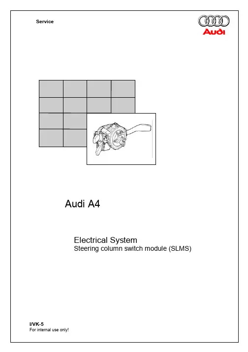
Contents:General function description Page 3Steering column electronicsmoduleCoil spring moduleSteering angle sensor Page 4Steering column switchCCS switch Page 6Ignition starter lock administrationElectronic steering wheel moduleSelf-diagnosis Page 7This trainer information is structured forself study programme 254 – Audi A4 2001and is not aWorkshop Manual!For maintenance and repair workplease use the currenttechnical literature.Function descriptionThe steering column electronics–J527 takeover the tasks of the steering column switchmodule and consists of the following:•Wattless signal processing of thesteering column switches – also CCS,•Evaluation of the ignition starter switch•Administration of the multi-function andtiptronic steering wheel•Control of the steering wheel heating•Diagnosis of all steering wheel andsteering column switch functions•Evaluation of the steering angle sensorand information transfer via the driveCAN busAll the individual components of the steeringcolumn switch module can be replacedindividually.Steering column electronicsThree steering column electronics versionsare available with different functions•Low-line (standard)- Turn signal switch recognition- Wiper switch recognition- On-board computer control- Horn switch- Steering angle determination•Mid-line with additional- CCS – switch recognition- Multi-function steering wheel control- Tiptronic function in steering wheel•High-line with additional- steering wheel heatingDue to the various wirings of the processor,refitting of the steering wheel is notstraightforward. The correct modulecombination must be therefore be checkedbeforehand.Coil spring moduleThree different versions of the module areavailable, depending on the steering wheelelectronics module.There is a coil spring module with1 band > airbag and horn only (standard)2 bands>with steering wheel operationfor tiptronic/multi-functionbuttons4 bands> with steering wheel heating Steering angle sensorThe visual unit of the steering wheel sensor islocked into the coil spring module and cannotbe replaced individually.Steering column switchThe relevant switch position is recognised viathe steering column electronicsmicroprocessor due to the voltage drop at thepull-up resistors.The switching current of the wattless switchesis between 10 and a maximum of 35 mA.The relevant switches can be checked via themeasured value blocks of the self diagnosisor via resistance measurement.Wiper switch PIN 1+6Resistance values (Tolerances are not taken into account)Rest position8703 O Step 1332 O Flick wipe332 O Intermittent1013 O Step 22513 O Washer switchPIN 1+5Rest position8703 O Windscreen washing332 O Rear window wiping1013 O Rear window washing2513 O Interval wipe potiPIN 1+2Switch defective9070 O Step 1240 O Step 2630 O Step 31380 O Step 42880 O On-board computerswitchPIN 1+3Rest position8703 O Reset332 O Cursor up1013 O Cursor down2513 OTurn signal PIN 1+6Resistance values (Tolerances are not taken into account)Rest position0 O Right2131 O Left681 O Main beamPIN 1+5Rest position0 O Headlamp flasher2131 O Main beam681 O Alarm for taxisPIN 1+3Rest position8O Pressed0 O Radio for taxisPIN 1+2Rest position / Switchdefective8O Pressed0 OCCS switch horizontal PIN 1+5Resistance values (Tolerances are not taken into account)Rest position 8371 O Resume2181 O Soft off681 O CCS switch, verticalPIN 1+6Rest position8371 O Accelerate2181 O Decelerate681 O CCS switchEngaged offPIN 1+7Rest position8O Engaged OFF 0 O CCS switchSet buttonPIN 1+2Rest position8O Set pressed 0 OSteering wheel heatingThe steering wheel heating is activated via the seat heating switch on the driver’s side independent of the heating level. The switch-on information is transferred by the climate control unit via the convenience CAN bus.When switched on, the heater is supplied with power for 2 seconds and is then set to a temperature of 21°C via an NTC in the steering wheel crown.Tiptronic buttonsWhen engaging the gear lever in the tiptronic gate, an earth potential is applied to the switch. The locating light is dimmed with the terminal 58s.Dimming of the switch lights is via theconvenience CAN bus from the dash panel insert. Testing via self diagnosis is possible.Self diagnosisAddress word16 – steering wheel electronics with ignition ON.Despite answerback in the diagnosis tester the steering wheel electronics respond.The actual steering wheel electronics module is interrogated via the steering wheel electronics.The self diagnosis is performed via the CCE, i.e. if the steering wheel electronics module isdiagnosed it is carried out via the convenience CAN bus > steering wheel electronics > steering column electronics > CCE > K-wire > diagnosis tester.Central Convenience Electronic (CCE)Steering column switch moduleSteering wheelmoduleKWP1281 via K-wireKWP1281via K-CANasynchronous interfaceEntry into fault memory (02)If the faultis displayed, adaption of the steeringcolumn electronics to the vehicle must be performed.Refer to …Adaption“Final control diagnosis test (030)In the final control diagnosis test the following functions can be activated depending on the available version.DisplayFunctionL o w -L i n e M i d -L i n e H i g h -L i n e Illumination / Switch and instrumentsLocating light is switched onX X XHeated steering wheelSteering wheel heating is switched onX Radio louder Radio volume increases X X Radio quieter Radio volume decreases X X Radio station search, upwards Upward search is started X X Radio station search,downwardsDownward search is started X X Telephone memory Telephone memory isdisplayedX X Next telephone memory Next telephone memory isdisplayedX X End Final control diagnosis test iscompletedX X X01794Control unit – wrong chassis numberCode (07)Measured value blocks (08)A chassis number is stored in channel 81 and is used for anti-theft protection.Please observe the procedure as described in …Adaption“.Input signals001Ignition starter switchTurn signalHeadlamp flasherMain beamsVersionsCodeUnallocated = 0XSteering wheel version0 = Standard steering wheel 1 = 3-spoke sports steering wheel2 = Multi-function steering wheel with radio control3 = Multi-function steering wheel with radio/telephone control4 = Multi-function steering wheel with radio/telephone and voice control system XSteering wheel version 0 = no tiptronic on steering wheel, no steering wheel heating1 = Tiptronic on steering wheel2 = Steering wheel heating3 = Tiptronic on steeringwheel with steering wheel heatingXOptional extras0 = No on-board computer no CCS1 = On-board computer (FIS)2 = CCS4 = On-board computer and CCS XRear wiper 1 = without 2 = withX0/1 > P-Contact0/1 > S-Contact (86s)0/1 > T. 750/1 > T. 150/1 >T. 50not actuatedleftrightnot actuatedactuatednot actuatedactuated002Horn Wiper,front Intermittent Wiper,frontnot actuated actuatednot actuatedIntermittent stepStep 1 (flick wipe also)Step 2Step 1Step 2Step 3Step 4not actuatedactuated003Wiper,rear:Wiper,rear:On-board computer(FIS)Unallocatednot installed not actuated actuated not installednot actuatedactuatednot installednot actuatedReset switch (645)On switch (643)Switch (644)Mid and high-line onlyCCS switch unit004CCSON/OFFCCS set CCS currently unallocatedON OFF not actuatedactuatednot actuatedacceleratedeceleratestored offReactivationSteering wheel module – tiptronic steering wheel005Switch down Switch up Steering wheelheatingTemp sensornot installed not actuated actuated not installednot actuatedactuatednot installedOnOffnot installedxx °CSteering wheel module – MFS (multi-function steering wheel)006MFLCommunicationMFLVersionFault inMFS?OK Not OK …Version…YesNo007MF button1MF button2MF button3MF button4not actuated actuated not actuatedactuatednot actuatedactuateddisabledenabledMWB 007/008F – door 0 F – door 1BF – door 0BF – door 1not installedDoor rl 0Door rl 1not installedDoor rr 0Door rr 1127Radio Telephone Language inputRadio 0 Radio 1Telephone 0Telephone 1Language 0Language 1Adaption (10)When installing a component that has already been used in another vehicle, adaption must be performed, as the chassis number is stored in channel 81 of the measured value block.The adaption must be activated using a control unit code (steering column electronics = 111).If the code number has been entered incorrectly 3 times in a row the adaption is blocked for a defined time frame.The …current“chassis number is transmitted by the dash panel insert via the convenience CAN bus after adaption has been carried out. When a new replacement part is used, this process is carried out automatically during initial operation.。
倒车摄像系统的校准在完成车辆的检修工作后,可能需要对倒车摄像系统进行校准,例如完成下面的工作后:t拆、装倒车摄像头-R189 -t更换倒车摄像系统控制单元 - J772 -t出现交通故障后修理过行李箱盖t车轮定位工作t修理前、后桥准备工作要想进行校准工作,必须将车辆停在坚固且平坦的地面上。
在测量过程中,车内不得坐人。
测量中车辆不可移动,不得打开和关闭车门。
行李箱盖应关上。
– 将VAS5051接到车上。
– 将转向角传感器- G85置于0位(摆正车轮)。
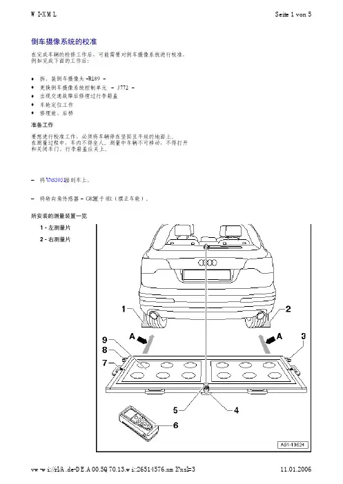
所安装的测量装置一览1 - 左测量片2 - 右测量片Seite 1 von 5WI-XML3 - 用于支撑距离测量仪的右侧角钢4 - 塑料座q3个,在校准板底部q可以调节,用于修正校准板的水平状态5 - 校准板上的划线激光q接通和关闭见使用说明书6 - 距离测量仪q操作说明见使用说明书7 - 校准板上的水平仪q用于检查校准板的水平状态8 - 用于支撑距离测量仪的左侧角钢9 - 校准盘上的测量区q距后桥1.47m - 1.90m(尺寸-A-)安装及调整测量装置– 检查一下轮辋有哪个分度圆。
– 将车轮接收器调至合适状态。
– 为此要拧紧分度圆上车轮螺栓的三个转接头。
– 将测量片放到两个车轮接收器上,并用夹紧螺栓固定。
– 将车轮接收器放到后车轮的车轮固定螺栓上。
于是车轮接收器就被“O型箍定位在转接头内并被固定住了。
说明– 接通校准板上的激光-1-并校准整个校准板的位置,使得激光束经后雨刮器轴照到车后部。
– 按压距离测量仪上的ON按键接通测量仪。
在激光的作用下会出现下面的显示内容。
– 请您像图示那样手持距离测量仪-2-,要将其靠紧在校准板的一侧,因此测量仪必须紧靠在角钢上。
– 必须保证距离测量仪发出的激光束照到测量片的大端-1-。
如果没有达到这个状态,那么必须用车轮接收器上的夹紧螺栓对测量片进行相应的调整。
– 用一支手按图示把住距离测量仪,这时应能看到激光束照到测量片上。
售后服务培训自学手册 335弯道照明灯系统结构和功能大众弯道照明灯系统包含两个新车灯功能:-动态弯道照明灯和-静态弯道照明灯。
与传统大灯相比,这两项功能可显著改善弯道行驶时和转弯时的路面照明情况。
在这本自学手册中将详细介绍弯道照明灯系统是如何工作的。
S335_02723概述. . . . . . . . . . . . . . . . . . . . . . . . . . . . . . 4系统概览. . . . . . . . . . . . . . . . . . . . . . . . . . . . 6CAN 通信 . . . . . . . . . . . . . . . . . . . . . . . . . . . 9动态弯道照明灯 . . . . . . . . . . . . . . . . . . . . . . . 10静态弯道照明灯. . . . . . . . . . . . . . . . . . . . . . . . 12结构. . . . . . . . . . . . . . . . . . . . . . . . . . . . . 14维修. . . . . . . . . . . . . . . . . . . . . . . . . . . . . .17自测试题. . . . . . . . . . . . . . . . . . . . . . . . . . . .18目录概述组件和安装位置下图给出了组成弯道照明灯系统所需要的控制单元和组件的安装位置。
安装位置在所有车型中几乎相同。
大灯照明距离调节控制单元J431,安装在组合仪表内。
带右侧大灯功率输出模块 J668 的右侧大灯带左侧大灯功率输出模块 J667 的左侧大灯ABS 控制单元 J104,安装在发动机舱内45弯道照明灯系统包含以下功能:-行驶期间使用的动态弯道照明灯(随动近光灯),-静态弯道照明灯,驶过急弯时(例如转弯时)可改善照明情况的一个附加照明装置。