ETS-D5 3564825说明书
- 格式:pdf
- 大小:706.41 KB
- 文档页数:6
Hinweis,Note,注意.................................de Die Ventilinsel ist ausschließlich zur Steuerung pneu-matischer Aktuatoren bestimmt.Hierbei sind die an-gegebenen Grenzwerte der technischen Daten einzu-halten.Ausführliche Informationen finden Sie in der Pneumatik-Beschreibung P.BE-VTSA-44-....en The valve terminal has been designed exclusively forcontrolling pneumatic actuators.The specified limits for technical data must be adhered to.Detailed in-formation can be found in the description of pneuma-tics P.BE-VTSA-44-....zh 该阀岛仅限用于控制气动执行元件。
使用时请务必遵守技术规范中所给出的极限值。
详细信息请参见气动部件说明书P.BE-VTSA-44-...。
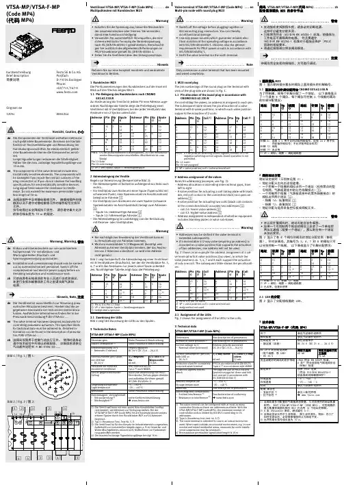
Ventilinsel VTSA-MP/VTSA-F-MP (Code MP4)de ..........Multipolknoten mit Rundstecker M231Rundstecker M23Die Pin-Nummerierungen des Rundsteckers auf der Insel mit Blick auf den Stecker zeigen Bild 1.1.1Pin-Belegung des Rundsteckers nach CNOMOE03.62.530.NZur Ansteuerung der Ventile ist jedem Pin eine Adresse zuge-ordnet.Nachfolgende Tabelle zeigt die Pinbelegung einer Ventilinsel mit 8Ventilplätzen,bei der jeder Ventilplatz das Ansteuern von 2Spulen unterstützt:2Adressbelegung der VentileRegeln zur Adressierung (Beispiel siehe Bild 2):–Die Adressvergabe ist lückenlos aufsteigend von links nach rechts.–Ein Ventilplatz zum Ansteuern einer Spule (Typenschild mit schwarzem Punkt,roter Spulenkontakt im Anschlussblock)belegt eine Adresse 3.–Ein Ventilplatz zum Ansteuern von zwei Spulen (schwarze Spulenkontakte im Anschlussblock)belegt zwei Adressen 4:–Spule 14:niederwertige Adresse 2–Spule 12:höherwertige Adresse 1–Die Adressbelegung ist unabhängig von der Bestückung mit Reserve-oder Ventilplatten.mit 8Ventilplätzen (Draufsicht),bei der die Ventilplätze Nr.3,4,7und 8das Ansteuern nur jeweils einer Spule unterstüt-zen.Nachfolgende Tabelle zeigt dazu die Pinbelegung:2.1Zuordnung der LEDsBild 2zeigt die Zuordnung der LEDs zu den Spulen.3Technische DatenVTSA-MP/VTSA-F-MP (Code MP4)AbmessungenSiehe Pneumatik-Beschreibung Anzahl Ventilplätze 1)Siehe Pneumatik-Beschreibung Ansteuerspannung 24V –Nennwert (Toleranz)verpolungssicherDC 24V (DC 21,6...26,4V)Stromaufnahme (pro Spule,mit LED)bei –DC 24V3/2-Wegeven-tile 60mA 5/2-und 5/3-Wegeventile 72mA Schutzart bei komplett montierter Ventilinsel IP65nach EN 60529,Typ 42)nach NEMASchutz gegen elektrischen SchlagDurch die Verwendung von PELV-Stromkreise (Schutz gegen direktes und indirektes Berühren gemäßIEC/DIN EN 60204-1)Umgebungstemperatur Lagertemperatur –5...+50°C –20...+40°CWerkstoffeSiehe Pneumatik-Beschreibung Elektromagnet.Verträglichkeit –Störaussendung 3)–Störfestigkeit 4)siehe Konformitätserklärung →1)Die Ventilinsel kann mit max.soviel Anschlussblöcken konfigu-riert werden,wie Adressen zur Verfügung stehen.Bei derVTSA-MP/VTSA-F-MP (code MP4)ist die maximale Anzahl ansteu-erbarer Spulen durch den Rundstecker M23auf 16Adressen begrenzt.2)Typ 4(Hosedown Test,Test-Nr.5.7)3)Die Ventilinsel ist für den Einsatz im Industriebereich vorgesehen.Außerhalb von industriellen Umgebungen,z.B.in Gewerbe-und Wohn-Mischgebieten,müssen evtl.Maßnahmen zur Funkentstö-rung getroffen werden.4)Die maximal zulässige Signalleitungslänge beträgt 10m.Valve terminal VTSA-MP/VTSA-F-MP (Code MP4)en ...Multi-pin node with round plug M231M23round plugThe pin numberings of the round plug on the terminal with view of the plug side are shown in Fig.1.1.1Pin allocation of the round plug in accordance withCNOMO E03.62.530.NFor controlling the valves,an address is assigned to each pin.The subsequent table shows the pin allocation of a valve terminal with 8valve positions,in which each valve position supports the actuation of 2coils:2Address assignment of the valvesRules for addressing (example,see Fig.2):–Address allocation in ascending order without gaps,from left to right.–A valve position for actuating a coil (rating plate with black dot,redcoil contact in the connection block)occupies an address 3.–A valve position for actuating two coils (black coil contacts in the connection block)occupies two addresses 4:–coil 14:lower-value address 2–coil 12:higher-value address 1–Address assignment is independent of whether equipment includes blanking plates or valve sub-bases.ve terminal with 8valve positions (top view),in which the valve positions no.3,4,7and 8each support the actuation of only one coil.The subsequent table shows the pin allocati-on:2.1Assignment of the LEDsFig.2shows the assignment of the LEDs to the coils.3Technical dataVTSA-MP/VTSA-F-MP (Code MP4)DimensionsSee description of pneumatics Number of valve positions 1)See description of pneumatics Control voltage 24V–Nominal value (tolerance)Reverse polarity protected DC 24V (DC 21.6...26.4V)Current consumption (per coil,with LED)at –DC 24V3/2-way valves60mA 5/2and 5/3-way valves72mAProtection class for completely mounted valve terminal IP65in accordance with EN 60529,Type 42)in accordance with NEMA Protection against electric shockThrough the use of PELV circuits (protection against direct and indi-rect contact in accordance with IEC/DIN EN 60204-1)Ambient temperature Storage temperature –5...+50°C –20...+40°CMaterialsSee description of pneumaticsElectromagnetic compatibility –Emitted interference 3)–Resistance to interference 4)See declaration of conformity →1)The valve terminal can be configured with at most as many connection blocks as there are addresses available.With the VTSA-MP/VTSA-F-MP (code MP4),the maximum number of controllable coils is limited by the M23round plug to 16addresses.2)Type 4(hosedown test,test no.5.7)3)The valve terminal is intended for use in an industrial environ-ment.When used outside an industrial environment,e.g.in com-mercial and mixed residential areas,measures for radio interfe-rence suppression may be necessary.4)The maximum permissible signal cable length is 10m.阀岛VTSA-MP/VTSA-F-MP(代码MP4)zh ............配备圆形插头M23的多针节点1圆形插头M23图1显示朝向插头看去时阀岛上圆形插头的针脚编号。
DMH5便携式多合一气体检测仪使用说明书重庆德镁科技有限公司目录1、概述 (1)2、技术性能及参数 (1)3、操作说明 (3)4、调校菜单 (11)5、日常使用与维护 (14)6、仪器贮存与质保 (14)7、产品成套性 (15)附录标定记录 (16)敬告用户在使用仪器前请仔细阅读本说明书1、概述本产品是一种外形小巧,方便携带,具有清晰液晶屏幕显示的便携式气体检测仪。
根据用户需求,本仪器可以任意搭载2~4种气体传感器,实现同时检测多种气体的功能。
仪器采用大容量可充电式锂电池供电,配备标准USB充电接口,同时具有声、光以及振动报警功能。
本产品可工作于环境恶劣的工业现场,精确的检测扩散环境中的各种可燃或有毒有害气体,并及时提醒工作人员注意防护。
2、技术性能及参数特点●可以同时支持2~4种的气体检测;●反应灵敏、检测精准、稳定可靠;●外形小巧、轻便坚固、防尘防震;●各通道可独立设置两级报警门限,具有声、光以及振动报警功能;●液晶大屏幕实时显示检测数值,具有告警通道指示功能;●具备开机自检功能以及恢复出厂设置功能;●操作方便、维护费用很低;●可以存储26万条数据,配有功能强大的数据分析软件系统(选配)主要技术指标注:如需检测其它气体或对检测气体量程有特殊要求的请与我们联系检测方式:扩散式供电方式:可充电3.7V 聚合物锂电池电池工作时间:连续工作180小时左右(可燃气为15小时)传感器工作原理:电化学式、催化燃烧式、非色散红外吸收式等传感器寿命:两年(可燃气为3年)显示方式:大液晶屏幕显示报警提示:声、光、振动报警防爆标志:Ex ibdIICT3防护等级:IP45工作温度:-10~40℃工作湿度:5-90%RH 尺寸:126mm (长)×66mm (宽)×32mm (厚)重量:220g (带充电器)3、操作说明开启仪器长按“”键,仪器发出嘀声后开机并进行自检。
关闭仪器在正常检测状态下,长按“”键,屏幕出现5秒倒计时后关机,如按“”键未持续到倒计时结束,仪器会自动返回正常检测状态。
JaRa 2108S/D双重防雷、光电隔离型RS-485中继器产品使用说明书1.产品简介2108系列产品是捷瑞公司专门针对工业应用而推出的高性能RS485光电隔离中继器。
采用亚当模块式设计,易于安装。
RS485端具有双重防静电防浪涌功能。
2108系列产品分为2种型号---2108S、2108D。
两种种产品外形尺寸以及使用都完全相同,唯一的区别是隔离方式不同。
2108S为单端隔离;2108D为双端隔离。
(详细区别见产品系统供电框图)2.2108S/D外形及引脚定义(注意:图中NC表示“未用”)说明:2108S为单端隔离。
此时,SG2与GND是同一个地。
但,与SG1不是同一个地2108D为双端隔离。
此时,SG1、SG2、GND三者不是同一个地2108S/D接上电源时,电源指示灯Power(红色)长亮当有数据由左向右传输时,指示灯>>>(绿色)闪烁当有数据由右向左传输时,指示灯<<<(绿色)闪烁3.性能参数接口标准 兼容EIA/TIA的RS485标准传输介质 普通双绞线传输距离 单端0---1.2Km,双端2400m,可使您的485网络再延长1200m通信速率 300---115.2Kbps挂接点数 32个标准节点隔离电压 2500V供电方式 在接线柱的VPP和GND之间接+9VDC~+24VDC直流电源信号 SG1端:A、B、SG1(可选);SG2端:A、B、SG2(可选)工作方式 半双工通信协议 透明工作温度 -10℃---50℃相对湿度 5%---95%备注:2108S/D的外部供电电源设计为可以从两端提供,既,将+9VDC~+24VDC直流电源接在2108S/D的任何一端都可以。
两端的电源地(GND)是相通的,但两端的电源VPP是不通的。
详细情况参见2108S/D的内部供电框图4.2108S/D的内部电源供电框图4.1 2108S(单端隔离)(注意:2108S的SG1端485的信号地(SG1)与电源地(GND)是同一个地)4.2 2108D(双端隔离)(注意:2108D的右信号地SG1、信号地SG2与电源地(GND)彼此不是同一个地)5.应用举例5.1 2108S/D并联方式扩展RS-485网络说明:并联2108S/D方式用于在同一个区域内扩展您的485通信网络,增加您的485网络的设备数量。

PARTS LIST(4)(7)(1)(2)No.DescriptionQty (1)Installation Instruction URL 1(2)Recoil starter 1(3) 6 mm flange bolt 4(4)Recoil pulley comp.1(5)12 mm flange bolt 1(6)O-Ring 1(7)Oil seal 1(8)Condenser unit1TOOLS AND SUPPLIES REQUIREDSocket (10 and 17 mm)RatchetRatchet extensionRecoil pulley holder (T/N: 075MB-HM70100)Engine oilTorque wrenchUSE AND CARE INFORMATION• Check the flange bolts periodically for the proper torque.• Do not pull the recoil starter grip while the engine is running.• If the starter grip does not return smoothly (because of dirt in the assembly), see your Honda dealer.• The recoil starter is used to start the engine when the battery is low.To operate the recoil starter:1. Turn the ignition switch to ON and engine stop switch to RUN.2. Check that the transmission is in neutral.3. Grasp the starter grip firmly, then pull it out slowly approximately 100 mm (4 in).4. Pull the grip up briskly and fully.5. After the engine starts, allow the starter grip to recoil slowly and then let go.ItemN·m kgf·m Ibf·ft 6 mm flange bolt 12 1.2912 mm flange bolt1081180TORQUE CHARTTighten all screws, bolts, and nuts to their specified torque values. Refer to the Service Manual for the torque values of the removed parts.STARTER GRIP<Right side>3. Disconnect the negative (-) cable from the battery.2. Refer to the Service Manual to remove the parts.INSTALLATIONradiator, etc. to cool before installing the accessory.NOTE:• Disconnect the negative (-) cable from the battery before installing this accessory.• The memories of the tripmeter and clock will be erased when you disconnect the battery. Reset the clock after reconnecting the battery.1. Refer to the model specific Service Manual toremove the indicated parts.<TRX500 SHOWN>4. Install the oil seal as shown. 6. Install the recoil starter as shown.7. Install the condenser unit as shown.5. Install the recoil pulley as shown. Use the special toolto hold the recoil pulley while torquing the flange bolt.• NOTE : The recoil pulley is keyed to the flywheel. Be sure to properly index the recoil pulley to the flywheel before installing the o-ring and bolt.(Reuse)<Inside the battery box>8. Connect the condenser unit harness as shown.OPERATION CHECKS AFTER INSTALLATION1. Check that the transmission is in neutral. Array2. Check that the negative (-) battery cable isdisconnected from the battery.3. Turn the ignition switch ON.4. Hold the recoil starter grip firmly and pull it vigorouslyto start the engine.5. Stop the engine. Turn the ignition switch OFF andreconnect the negative (-) battery cable securely.• Note that the above procedure is for checkingfunctions after installation only. Normally,use the recoil starter with the battery cablesconnected.9. Reinstall the removed ATV parts.。

Eaton 118701Eaton ESR5 Safety relay emergency stop/protective door, 24VDC/AC, 4 enabling pathsEspecificaciones generalesEaton ESR5 Safety relay 1187014015081168415114.5 mm 99 mm 22.5 mm 0.218 kgUL Category Control No.: NKCR; NKCR7Certified by UL for use in Canada CSA-C22.2 No. 14-95 IEC 62061 ULCSA Class No.: 3211-83; 3211-03 UL File No.: E29184 IEC 61508, Parts 1-7 EN ISO 13849-1 EN 50178 2014/30/EU IEC/EN 60204 CE UL 508UL report applies to both US and CanadaMachines 2006/42/EGESR5-NO-41-24VAC-DCProduct NameCatalog Number EANProduct Length/Depth Product Height Product Width Product Weight CertificationsModel CodeScrew connection4 Non-delayed enable current pathsAutomatic startReinforced insulation6 kV between input circuit / NC contacts, and enable current pathsManual startSafe insulationBasic insulationFeedback circuitApproval for TÜVDetachable clampsStart inputApproval according to UL1-channelEnclosure: Polyamide (PA), not reinforcedContacts: silver tin oxide, gold plated (AgSnO2, 0.2 µ m Au)M3 screw terminals140 mA, AC65 mA, DCIP20Installation location: ≥ IP54Terminals: IP20Enclosure: IP20100 %According to EN 61000-6-4According to EN 61000-6-2Status indication of SmartWire-DT network: Green LED 10,000,000 OperationsBasic deviceRail mounting possibleTop-hat rail fixing (according to IEC/EN 60715, 35 mm) 22.5 mmIII2Normally 5.16 WElectronic safety relaysElectric connection type FeaturesFitted with:FunctionsMaterial Connection type Current consumption Degree of protection Duty factorEmitted interference Interference immunity LED indicator Lifespan, mechanical ModelMounting method Mounting width Overvoltage category Pollution degree Power lossProduct category ProtectionFinger and back-of-hand proof, Protection against direct contact when actuated from front (EN 50274)4000 V AC1000 msLevel cSIL 1, Safety integrity level, In accordance with IEC 61508 SILCL 1, Safety integrity level claim limitCat. 1, Category4.05 x 10-10, PFHd, Probability of failure per hourModule used to safely interrupt electrical circuitsMonitoring of position switchesMonitoring of emergency-stop circuitsSafety relay for monitoring emergency stop and protective door switchMax. 0.5 Hz, Input dataAC/DC As required240 Months (High Demand)167 Months (Low Demand)3 A at 3600 O/h, AC-15 at 230 V, Outputs0.4 W4 A at 360 O/h, AC-15 at 230 V, OutputsIn accordance with IEC 60947-5-1, Outputs4 A at 360 O/h, DC-13 at 24 V, Outputs2.5 A at 3600 O/h, DC-13 at 24 V, Outputs10 - 150 Hz, Amplitude: 0.15 mm, Acceleration: 2 g, (IEC/EN 60068-2-6)795 - 1080 hPa (operation)Max. 2000 m-20 °C55 °C-40 °C70 °CDry heat to IEC 60068-2-2Damp heat, constant, to IEC 60068-2-3Clearance in air and creepage distances according to EN 50178, UL 508, CSA C22.2, No. 14-95Condensation: Non-condensingRated impulse withstand voltage (Uimp) Recovery timeSafety performance level (EN ISO 13849-1) Safety parameter (IEC 62061)Stop category (IEC 60204)Suitable forSwitching frequencyTypeVoltage type Mounting positionProoftestSwitching capacityVibration resistanceAir pressureAltitudeAmbient operating temperature - min Ambient operating temperature - max Ambient storage temperature - min Ambient storage temperature - max Climatic proofingEnvironmental conditionsOperating temperature - minEmergency stop category 0; emergency switching off Feedback circuitProtective door-20 °C 55 °C< 75 %2 x (0.2 – 1) mm², solid1 x (0.25 – 2.5) mm², flexible with ferrule2 x (0.25 – 1) mm², flexible with ferrule 24 - 12 AWG, solid or stranded1 x (0.2 – 2.5) mm², solid7 mm0.6 x 3.5 mm, Terminal screws2, Terminal screw, Pozidriv screwdriver 0.6 Nm, Screw terminals0.025 - 6 A1.6 W (DC operated)3.4 W (AC operated 50/60 Hz) 0 V26.4 V20.4 V24 V0 V24 V250 V24 V AC/DC (power supply) 1500 VA, max., resistive load (τ = 0 ms), at 250 V AC 42 W max., inductive load (τ = 40 ms), at 24 V DC 88 W max., resistive load (τ = 0 ms), at 220 V DC 288 W max., resistive load (τ = 0 ms), at 48 V DC 144 W max., resistive load (τ = 0 ms), at 24 V DC42 W max., inductive load (τ = 40 ms), at 220 V DC 42 W max., inductive load (τ = 40 ms), at 48 V DC 110 W max., resistive load (τ = 0 ms), at 110 V DC 42 W max., inductive load (τ = 40 ms), at 110 V DC∞ ms, Simultaneity for inputs 1/265 AOne- and two-channel4Operating temperature - maxRelative humidityTerminal capacityStripping length (main cable)Screwdriver sizeTightening torqueInrush currentPower supply circuitRated control supply voltage (Us) at AC, 50 Hz - min Rated control supply voltage (Us) at AC, 50 Hz - max Rated control supply voltage (Us) at AC, 60 Hz - min Rated control supply voltage (Us) at AC, 60 Hz - max Rated control supply voltage (Us) at DC - minRated control supply voltage (Us) at DC - max Rated insulation voltage (Ui)Rated operational voltage Breaking powerInputNominal currentNumber of inputsNumber of outputs (safety related, delayed) with contact Number of outputs (safety related, undelayed) with contact Number of outputs (signaling function, delayed) with contact230 V ACApprox. 24 V DC at input, starting and feedback circuit2.3 A, Input dataShort-circuit proof, 24 V, Fuse for control circuit supply, Control circuitMiniature circuit-breaker with characteristic C: 24 V AC/DC 6 A, For output circuits, ExternalFuse 6 A gL/gG, For output circuits, External6 A, Output fuse, Output data 122 Ω (input and starting circuits for UN)65 ms typ. (K1, K2 - for UN automatic mode) 20 ms typ.72 A² (ITH² = I1² + I2² + I3² + I4²)45 ms22 Ω (impedance)250 V6 A N/O, Limiting continuous current3 A N/C, Limiting continuous current0 W0 W0 W0 A5.16 WMeets the product standard's requirements. Meets the product standard's requirements. Meets the product standard's requirements.eaton-safety-relays-esr5-safety-relay-characteristic-curve-009.eps eaton-safety-relays-esr5-safety-relay-characteristic-curve-008.epseaton-safety-relays-relay-esr5-safety-relay-dimensions-002.eps eaton-safety-relays-relay-esr5-safety-relay-3d-drawing.eps eaton-general-esr5-safety-relay-symbol.epseaton-general-technology-esr5-safety-relay-symbol.epsDA-CE-ETN.ESR5-NO-41-24VAC-DCeaton-safety-relays-esr5-safety-relay-wiring-diagram-005.eps eaton-safety-relays-esr5-safety-relay-wiring-diagram-004.eps eaton-safety-relays-esr5-safety-relay-wiring-diagram-006.epsDA-DC-00004584.pdfDA-DC-00004576.pdfShort-circuit currentShort-circuit protection Short-circuit protection rating Number of outputs (signaling function, undelayed) with contact Permissible total cable resistancePick-up timeQuadratic summation currentReset timeResistanceSwitching voltageUninterrupted currentEquipment heat dissipation, current-dependent PvidHeat dissipation capacity PdissHeat dissipation per pole, current-dependent PvidRated operational current for specified heat dissipation (In) Static heat dissipation, non-current-dependent Pvs10.2.2 Corrosion resistance10.2.3.1 Verification of thermal stability of enclosures10.2.3.2 Verification of resistance of insulating materials to normal heat Characteristic curve DibujoseCAD model Esquemas eléctricosInformes de certificaciónMeets the product standard's requirements.Meets the product standard's requirements.Does not apply, since the entire switchgear needs to be evaluated.Does not apply, since the entire switchgear needs to be evaluated.Meets the product standard's requirements.Does not apply, since the entire switchgear needs to be evaluated.Meets the product standard's requirements.Does not apply, since the entire switchgear needs to be evaluated.Does not apply, since the entire switchgear needs to be evaluated.Is the panel builder's responsibility.Is the panel builder's responsibility.Is the panel builder's responsibility.Is the panel builder's responsibility.Is the panel builder's responsibility.The panel builder is responsible for the temperature rise calculation. Eaton will provide heat dissipation data for the devices.IL05013028ZDA-CS-esr5_no41_nz21 DA-CD-esr5_no41_nz2110.2.3.3 Resist. of insul. mat. to abnormal heat/fire by internal elect. effects10.2.4 Resistance to ultra-violet (UV) radiation10.2.5 Lifting10.2.6 Mechanical impact10.2.7 Inscriptions10.3 Degree of protection of assemblies10.4 Clearances and creepage distances10.5 Protection against electric shock10.6 Incorporation of switching devices and components10.7 Internal electrical circuits and connections10.8 Connections for external conductors10.9.2 Power-frequency electric strength10.9.3 Impulse withstand voltage10.9.4 Testing of enclosures made of insulating material10.10 Temperature rise10.11 Short-circuit rating Instrucciones de montaje mCAD modelEaton Corporation plc Eaton House30 Pembroke Road Dublin 4, Ireland © 2023 Eaton. All Rights Reserved. Eaton is a registered trademark.All other trademarks areproperty of their respectiveowners./socialmediaIs the panel builder's responsibility. The specifications for the switchgear must be observed.Is the panel builder's responsibility. The specifications for the switchgear must be observed.The device meets the requirements, provided the information in the instruction leaflet (IL) is observed.10.12 Electromagnetic compatibility10.13 Mechanical function。

D V - 5 6 8 D S DUser manual使用手冊DV-568DSD感謝您購買 DIVIN 專業葡萄酒櫃請將您的購買發票保存在手冊中重要使用指南∙在使用本產品前請先詳讀所有注意事項∙產品設計為商業或一般居家用途(限於室內),專為儲存各式葡萄酒,若酒櫃被用來做儲酒以外的用途時,我們將無法提供任何保障∙為了避免觸電的危險,請勿將酒櫃、電線插頭靠近積水處使用;請使用於乾燥且平坦的室內環境(不包含車庫);請勿在手濕的情況下操作產品∙擺放酒櫃的室內空間溫度應在5°至35°C 之間。
如果溫度高於或低於此範圍,則會影響酒櫃的功能,並可能導致酒櫃的溫度不穩定或不能達到所需的溫度∙請勿將酒櫃或其部件靠近任何發熱的電器用品(如瓦斯爐、暖爐等)、火源以及其他可燃氣體或液體,並避免將酒櫃擺放在陽光直射處∙建議在酒櫃使用前進行清潔,可提前做好保養;請勿使用可燃性液體清潔酒櫃,避免揮發氣體造成火災或爆炸∙延長線不建議使用,請使用獨立且符合安規的插座,拔除酒櫃電源線插頭時請勿直接拉扯電線∙不建議孩童操作酒櫃,請留意孩童安全∙請定期留意酒櫃內外部整潔並避免藏酒在酒櫃內有溢出的情況∙請確認產品正面下方的散熱孔周圍是通風的,並無任何物品阻礙空氣循環∙若您需長期停止使用此產品,請在關機後將櫃門打開通風乾燥 (避免過多水氣停留在內導致零配件受潮),之後可將櫃門上鎖以防止孩童玩耍不慎受傷。
∙請確保產品所在的空間是通風良好的∙酒櫃配有自動除霜系統,請勿使用其他方式來加速除霜過程∙移動酒櫃前請先將櫃內儲藏的酒先行移出以減輕搬運時的重量和顧及安全∙保固僅適用於酒櫃本身,並不包含保存之內容物∙如要丟棄此產品,請將此產品交由授權的大型電器回收廠DV-568DSD觸控式智慧控制面板*智慧控制面板為觸控式,只需輕輕觸碰按鍵即可操作,不需大力按壓H HL L溫度設定酒櫃溫度設定主要是依照您的用酒需求和葡萄酒款而定,假設您的收藏當中具有陳年潛力跟適合即飲的酒款,則建議將酒櫃上層規劃為即飲專用,下層規劃為熟成專用。

The 4850-TR HART multiplexer provides a simple interface between smart devices in the field; Triconex safety systems and FDT based HART® instrument management software running on a PC.The system is based on 32-channel modularity to provide a compact,easily configurable and expandable system. Using a standard RS485serial link, up to 992 individual HART® devices can be connected to a single network.For the optimum solution , the 4850-TR mounts directly to eitherthe Tricon (Interface) card or the Trident backplanes via a 100-way connector.Connectivity to HART Configuration and Asset Management Software The online access to the information contained within HART devices allows users to diagnose field device troubles before they lead to costly problems. Software such as PACTWARE can capture and use diagnostic data from HART field instruments via the MTL HART connectionhardware. This allows users to realise the full potential of their field devices to optimise plant assets, which results in significant operations improvement and direct maintenance savings.MTL4850-TRTriconix 4850 HART® multiplexerIMS products provide essential configuration , calibration, monitoring and maintenance history functions for conventional analog (4-20 mA) and HART protocol compatible smart process instrumentsand field devices. They deliver powerful tools to meet the need forstandardised instrument maintenance procedures and record keepingmandated by some quality standards and regulatory bodies.The benefits of utilising these powerful software packages onlineinclude:• Reduced commissioning time and costs • Reduced maintenance costs • Reduced documentation • Reduced process downtimeThe 4850-TR will offer connectivity to a comprehensive range of FDT based software packages via the 4850-TR Device Type Manager (DTM). The DTM can be downloaded from .• Designed to mount directly to T ricon Interface cards and T rident backplanes• Designed for use in SIL3 loops (non interfering)• Connect up to 992 loops on one RS485 network •Auto baud rate detection• Automatic addressing for T ricon and T rident systems • LED indication for fault diagnosis • Isolated Power Supply • Firmware upgradeable • Onboard Diagnostics •Alarm outputHART ® is a registered trademark of the HART Communication FoundationEaton Electric Limited,Great Marlings, Butterfield, Luton Beds, LU2 8DL, UK.Tel: + 44 (0)1582 723633 Fax: + 44 (0)1582 422283E-mail:********************© 2016 EatonAll Rights ReservedPublication No. EPS MTL4850-TR Rev 3November 2016Workstation PC running instrument management softwareand valvesTrident HART AO or AI baseplateTRIDENT APPLICATIONTRICON APPLICATIONS y s t e mWorkstation PC running instrument management softwareInput signals can be IS or non-IS.MTL isolatorsshould be used for IS field devices.SPECIFICATIONNumber of Channels32Channel T ransmitter T ypeHART rev 5 - 7Channel Isolation (Between Channels)50V dcChannel Interface2 connections to each channel field loop (64 total)Field Loop Isolation50V dcModule is coupled to loops via capacitor in each connection leg (i.e. 2 capacitors per channel)Host System InterfaceRS485 2-wire multidrop(up to 31 MTL4850 modules can be connected to one host) RS485 Interface Isolation (Between module and interface) 25VDCRS485 Baud Rate38400, 19200, 9600, 1200 (auto-detected)Address Selection8-bit interface, up to 64Interface referenced to 0V selectable addresses Address Interface Isolation (Between module and interface) 50VDCAlarm Output (Open Collector - Referenced to 0V) Vmax = 35VImax = 5mAPmax = 100mWAlarm Output Isolation (Between module and output) 50VDCPower RequirementMin = 19VMax = 35V24V +/-10% @ 60mAPSU Isolation (Between module and PSU input)50V dcPower Dissipation<1.6W @ 24V +/-10%PSU ProtectionReversed polarity protectedFused (375mA)T emperature RangeOperating: -40°C to +70°CNon-operating: -40°C to +85°CRelative Humidity5% to 95% - non-condensingCompatible FDT Frames include:-FDT Frame ManufacturerFDM HoneywellFieldCare Endress & Hauser/Metso Automation PACTware PACTware ConsortiumFieldMate YokogawaFDT Container M&M Software LED INDICATORSLED Colour State DescriptionPWR green Off Multiplexer is not receivingpowerOn Multiplexer is receiving power FAULT red Off Multiplexer is in the runningstateSteadyflashMultiplexer rebuild is in progressShort/longflashNo HART loops foundOn(steady)A fault was detected andmultiplexer operation has halted HOST yellow Off No communication on thechannelShortflash(0.25 sec)Correctly framed messagereceived by the multiplexerLong flash(1 sec)Response transmitted—thisis re-triggerable so repeatedtransmissions will leave theindicator permanently on HART yellow Off No communication on thechannelShortflash(0.25 sec)Message transmittedLong flash(1 sec)Response transmitted—thisis re-triggerable so repeatedtransmissions will leave theindicator permanently on ORDERING INFORMATIONMTL4850-TR 32-channel HART multiplexerThe given data is only intended as a product description and should not be regarded as a legal warranty of properties or guarantee. In the interest of further technical developments, we reserve the right to make design changes.DIMENSIONSMounting on caddy for Tricon Interface CardMounting on Trident AI or AO backplaneAPPROVALSThe given data is only intended as a productdescription and should not be regarded as a legal warranty of properties or guarantee. In the interest of further technical developments, we reserve the right to make design changes.Eaton Electric Limited,Great Marlings, Butterfield, Luton Beds, LU2 8DL, UK.Tel: + 44 (0)1582 723633 Fax: + 44 (0)1582 422283E-mail:********************© 2016 EatonAll Rights ReservedPublication No. EPS MTL4850-TR Rev 3 081116November 2016EUROPE (EMEA): +44 (0)1582 723633 ********************THE AMERICAS: +1 800 835 7075*********************ASIA-PACIFIC: +65 6 645 9888***********************。
布瑞特单圈绝对值旋转编码器RS485产品说明书深圳布瑞特科技有限公司ShenZhen Briter Technology Co.Ltd产品优势特性●RS485数字通讯信号输出,数字输出信号既有多圈值、单圈绝对值;●采用标准的ModBus-RTU通讯规约,支持组态王、Intouch、FIX、synall 等流行软件,能与AB、西门子、施耐德、GE等国际著名品牌的设备及系统之间实现数据通信;●单圈编码器在不掉电情况下可作电子多圈编码器使用(此功能非断电记忆),最高可达百万圈;增加返回速度功能,便于使用者计算;●单圈量程范围内任何位置都是唯一的,即使有干扰或断电运动,都不会丢失位置信息;●单圈分辨率有1024(10bit)、4096(12bit)、16384(14bit)、32768(15 bit),量程范围内最高可实现0.01度的分辨率;●所有参数均可通过电脑的RS485通讯进行设定,可在任意位置设定零点,因此安装编码器时可将设备停留任意位置,无需考虑本编码器的旋转位置、即可固定好连接轴,通电后只要在外部引线处或通过RS485通讯进行一次置零操作即可自动修正;●特别适用于塔式起重机、矿山起重机、施工升降机、机床、3D打印机、自动化流水线、工业机器人、印刷机械、包装机械、物流机械、移动广告屏幕滑轨等设备的高度、行程、角度及速度的可靠/精确测量。
产品型号说明型号:RS485接口--3D 模型以及相关资料请到布瑞特科技官网下载。
尺寸型号图1:输出6mm IP54尺寸型号图2:输出轴8mm IP54机械尺寸线出口方向与3个M3安装孔的角度关系是随机的D 字型轴尺寸比例5:1螺纹孔深6mm尺寸型号图3:盲孔8mm IP54尺寸型号图4:输出6mm IP67尺寸型号图5:输出8mm IP67注意事项●编码器属于精密仪器,请轻拿轻放、小心使用,尤其对编码器轴请勿敲、撞击及硬拽等。
●编码器与机械连接应选用柔性连接器或弹性支架,应避免刚性联接不同心造成的硬性损坏。
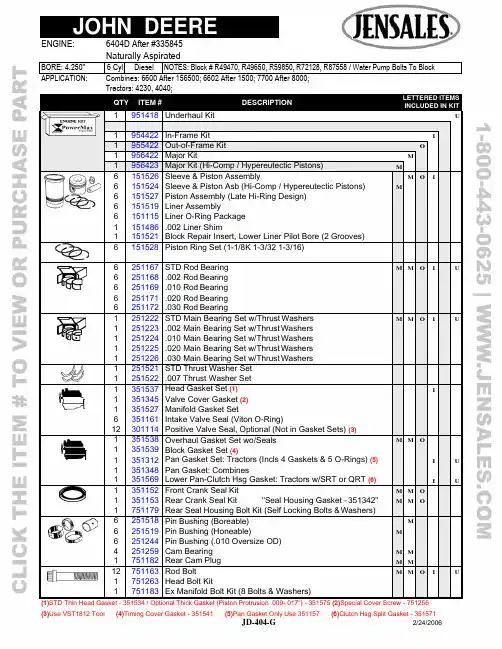
APPLICATION: Combines: 6600 After 156500; 6602 After 1500; 7700 After 8000;Tractors: 4230, 4040;QTY ITEM # DESCRIPTION LETTERED ITEMSINCLUDED IN KIT1 951418 Underhaul Kit U1 954422 In-Frame Kit I1 955422 Out-of-Frame Kit O1 956422 Major Kit M 1 956423 Major Kit (Hi-Comp / Hypereutectic Pistons) M6 6 6 6 6 1 1 151526 151524 151527 151519 151115 151486 151521 Sleeve & Piston Assembly Sleeve & Piston Asb (Hi-Comp / Hypereutectic Pistons) Piston Assembly (Late Hi-Ring Design)Liner AssemblyLiner O-Ring Package.002 Liner ShimBlock Repair Insert, Lower Liner Pilot Bore (2 Grooves)MM O I6 151528 Piston Ring Set (1-1/8K 1-3/32 1-3/16)6 6 6 6 6 251167 251168 251169 251171 251172 STD Rod Bearing .002 Rod Bearing.010 Rod Bearing.020 Rod Bearing.030 Rod BearingM M O I U1 1 1 1 1 251222 251223 251224 251225 251226 STD Main Bearing Set w/Thrust Washers .002 Main Bearing Set w/Thrust Washers.010 Main Bearing Set w/Thrust Washers.020 Main Bearing Set w/Thrust Washers.030 Main Bearing Set w/Thrust WashersM M O I U1 1 251521 251522 STD Thrust Washer Set .007 Thrust Washer Set1 1 1 6 12 351537 351345 351527 351161 301114 Head Gasket Set (1) Valve Cover Gasket (2)Manifold Gasket SetIntake Valve Seal (Viton O-Ring)Positive Valve Seal, Optional (Not in Gasket Sets) (3)I1 1 1 1 1 351538 351539 351312 351348 351569 Overhaul Gasket Set wo/Seals Block Gasket Set (4)Pan Gasket Set: Tractors (Incls 4 Gaskets & 5 O-Rings) (5) Pan Gasket: CombinesLower Pan-Clutch Hsg Gasket: Tractors w/SRT or QRT (6) M M O I IUU1 1 1 351152 351153 751179 Front Crank Seal Kit Rear Crank Seal Kit "Seal Housing Gasket - 351342" Rear Seal Housing Bolt Kit (Self Locking Bolts & W ashers)M M M M O O6 6 6 4 1 251518 251519 251244 251259 751182 Pin Bushing (Boreable) Pin Bushing (Honeable) Pin Bushing (.010 Oversize OD) Cam Bearing Rear Cam Plug M M M MMM12 1 1 751163 751263 751183 Rod Bolt Head Bolt KitEx Manifold Bolt Kit (8 Bolts & Washers)M M O I U(1)STD Thin Head Gasket - 351534 / Optional Thick Gasket (Piston Protrusion .009-.017") - 351575 (2)Special Cover Screw - 751256APPLICATION: Combines: 6600 After 156500; 6602 After 1500; 7700 After 8000;Tractors: 4230, 4040;QTY ITEM # DESCRIPTION LETTERED ITEMSINCLUDED IN KIT1 959513 Camshaft Kit C1 959313 Basic Valve Kit B1 959113 Valve Train Kit, Thru #532429 V1 959146 Valve Train Kit, After #532429 V1 551191Camshaft (7) (8) C 1 551186 Cam Thrust Plate (4 Bolt / .187" Thick)1 551278 Cam Gear Bolt, Late or Replacement Cam (1/2 x 2.000") (9)12 551181 Tappet C6 451216 STD Exhaust Valve (10) V V B6 451217 STD Intake Valve (11) V V B12 401141 Service Repair Valve Guide (.502" OD / 3.062" OAL) (12)12 451115 Valve Spring V V B6 451187 Exhaust Rotator V V6 451411 Intake Retainer, Thru #5324296 451187 Intake Rotator, After #532429 V12 451198 Valve Wear Cap24 451164 Keeper (Half) V V B6 451412 STD Exhaust Seat (1.500x1.750x.250) ".010 OS - 451414"6 451413 STD Intake Seat (1.687x1.937x.250) ".010 OS - 451415"6 451257 Rocker Arm, LH6 451258 Rocker Arm, RH1 451264 Rocker Arm Shaft (13) (14)1 551279 Cam Timing Gear1 551182 Crank Timing Gear, Early Design Crank (.750" Wide)1 551158 Crank Timing Gear, Late Design Crank (.910" Wide)1 551281 Injection Pump Drive Gear12 551277 Push Rod1 651216 Oil Pump: Combines1 651218 Oil Pump Drive Gear/Shaft 1 651215 Oil Pump Gear Set1 651221 Oil Pump Intake Screen: Tractors1 651217 Oil Cooler1 751123 Crankshaft (6 Bolt Flange)1 751265 Crank Update Parts Kit (2 Keys, 2 Plugs, Dowel Pin, Gear)1 751151 Damper Pulley: Tractors1 751266 Damper Pulley: Combines6 751255 Connecting Rod "Cap Alignment Sleeve - 751262"1 851365 Fuel Pump2 851211 Thermostat: Tractors (180 Degree) (15)2 851174 Thermostat: Combines (180 Degree)1 851255 Water Pump: Tractors "Overhaul Kit w/Impeller - 851256"1 851254 Water Pump: Combine "Overhaul Kit w/Impeller - 851257"1 851248 Block Heater (Press Fit Design)1 851249 Block Heater (Threaded Plug Design)(7)Cam Key - 551173 (8).193" Gear Spacer - 551198 (9)Cam Gear Washer - 551194(10)Oversizes: .003 - 451394 / .015 - 451395 / .030 - 451396 (11)Oversizes: .003 - 451397 / .015 - 451398 / .030 - 451399。
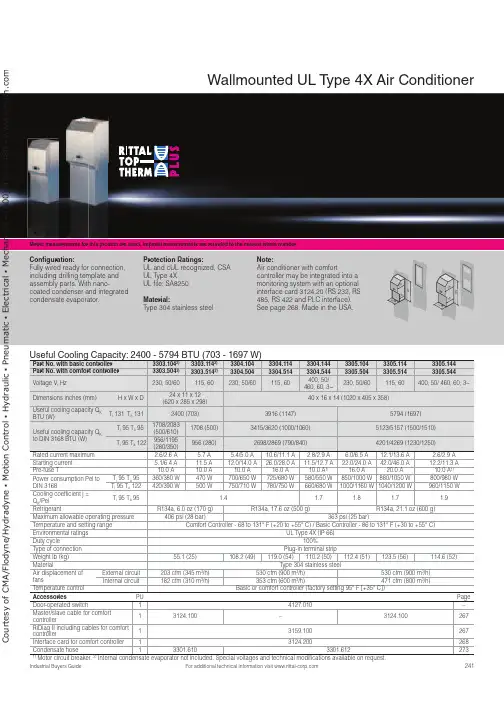
241For additional technical information visit Metric measurements for this product are exact, imperial measurements are rounded to the nearest whole numberUseful Cooling Capacity: 2400 - 5794 BTU (703 - 1697 W)Part No. with basic controller 3303.1042)3303.1142)3304.1043304.1143304.1443305.1043305.1143305.144Part No. with comfort controller 3303.5042)3303.5142)3304.5043304.5143304.5443305.5043305.5143305.544Voltage V , Hz230, 50/60115, 60230, 50/60115, 60400, 50/ 460, 60, 3~230, 50/60115, 60400, 50/ 460, 60, 3~Dimensions inches (mm)H x W x D24 x 11 x 12 (620 x 285 x 298)40 x 16 x 14 (1020 x 405 x 358)Useful cooling capacity Q KBTU (W)T i 131 T a 1312400 (703)3916 (1147)5794 (1697)Useful cooling capacity Q K to DIN 3168 BTU (W)T i 95 T a 951708/2083(500/610)1708 (500)3415/3620 (1000/1060)5123/5157 (1500/1510)T i 95 T a 122956/1195(280/350)956 (280)2698/2869 (790/840)4201/4269 (1230/1250)Rated current maximum 2.6/2.6 A 5.7 A 5.4/5.0 A 10.6/11.1 A 2.8/2.9 A 6.0/6.5 A 12.1/13.6 A 2.6/2.9 A Starting current 5.1/6.4 A 11.5 A 12.0/14.0 A 26.0/28.0 A 11.5/12.7 A 22.0/24.0 A 42.0/46.0 A 12.2/11.3 A Pre-fuse T 10.0 A 10.0 A 10.0 A 16.0 A 10.0 A 1)16.0 A 20.0 A 10.0 A 1)Power consumption Pel toDIN 3168T i 95 T a 95360/380 W 470 W 700/650 W 725/680 W 580/550 W 850/1000 W 880/1050 W 800/980 W T i 95 T a 122420/390 W500 W 750/710 W 780/750 W 660/680 W 1000/1160 W 1040/1200 W 960/1150 W Cooling coefficient j =Q K /PelT i 95 T a 95 1.4 1.7 1.8 1.7 1.9Refrigerant R134a, 6.0 oz (170 g)R134a, 17.6 oz (500 g)R134a, 21.1 oz (600 g)Maximum allowable operating pressure 406 psi (28 bar)363 psi (25 bar)Temperature and setting range Comfort Controller - 68 to 131° F (+20 to +55° C) / Basic Controller - 86 to 131° F (+30 to +55° C)Environmental ratings UL Type 4X (IP 66)Duty cycle 100%Type of connection Plug-in terminal strip Weight lb (kg)55.1 (25)108.2 (49)119.0 (54)110.2 (50)112.4 (51)123.5 (56)114.6 (52)Material Type 304 stainless steelAir displacement offans External circuit 203 cfm (345 m 3/h)530 cfm (900 m 3/h)530 cfm (900 m 3/h)Internal circuit 182 cfm (310 m 3/h)353 cfm (600 m 3/h)471 cfm (800 m 3/h)Temperature control Basic or comfort controller (factory setting 95° F [+35° C])Accessories PU Page Door-operated switch 14127.010–Master/slave cable for comfortcontroller13124.100–3124.100267RiDiag II including cables for comfortcontroller13159.100267Interface card for comfort controller 13124.200268Condensate hose 13301.6103301.6122731) Motor circuit breaker. 2)Internal condensate evaporator not included. Special voltages and technical modifications available on request.Wallmounted UL T ype 4X Air ConditionerCon guration:Fully wired ready for connection, including drilling template and assembly parts. With nano-coated condenser and integrated condensate evaporator.Protection Ratings:UL and cUL recognized, CSA UL Type 4XUL file: SA8250 Material:Type 304 stainless steel Note:Air conditioner with comfortcontroller may be integrated into a monitoring system with an optional interface card 3124.20 (RS 232, RS 485, RS 422 and PLC interface). See page 268. Made in the USA.000C o u r t e s y o f C M A /F l o d y n e /H y d r a d y n e ŀ M o t i o n C o n t r o l ŀ H y d r a u l i c ŀ P n e u m a t i c ŀ E l e c t r i c a l ŀ M e c h a n i c a l ŀ (800) 426-5480 ŀ w w w .c m a f h .c o242For additional technical information visit Metric measurements for this product are exact, imperial measurements are rounded to the nearest whole numberUseful Cooling Capacity: 8706 - 10525 BTU (2550 - 3083 W)Part No. with basic controller 3328.1043328.1143328.1443329.1043329.1143329.144Part No. with comfort controller 3328.5043328.5143328.5443329.5043329.5143329.544Rated operating voltage V , Hz 230, 50/60115, 50/60400, 50/460, 60, 3~230, 50/60115, 50/60400, 50/460, 60, 3~Dimensions inches (mm)H x W x D 65 x 16 x 15 (1650 x 405 x 388)Useful cooling capacity Q K BTU (W)T i 131 T a 1318706 (2550)10525 (3083)Useful cooling capacity Q K to DIN 3168 BTU (W)T i 95 T a 956860/8025 (2000/2350)8538/9392 (2500/2750)T i 95 T a 1224952/5772 (1450/1690)5464/5977 (1600/1750)Rated current max. 7.5 A/9.1 A 14.7 A/17.3 A 2.8 A/3.3 A 8.6 A/10.6 A 17.0 A/22.0 A 3.7 A/3.8 A Start-up current 22.0 A/26.0 A36.0 A/39.0 A6.8 A/7.8 A 21.0 A/21.0 A44.0 A/42.0 A6.8 A/7.6 A Pre-fuse T16.0 A25.0 A 10.0A/10.0 A 1)16.0 A 25.0 A 10.0 A/10.0 A 1)Power consumption Pel to DIN 3168 T i 95 T a 951025/1200 W 1085/1250 W 1050/1275 W 1450/1675 W 1500/1725 W 1425/1625 W T i 95 T a 1221250/1350 W1300/1410 W1275/1525 W1625/2000 W1675/2065 W1675/1975 WCooling coefficient j = Q K /Pel T i 95 T a 951.72.31.92.0RefrigerantR134a, 31.7 oz (900 g)Maximum allowable operating pressure 406 psi (28 bar)Temperature and setting range Comfort Controller - 68 to 131° F (+20 to +55° C) / Basic Controller - 86 to 131° F (+30 to +55° C)Protection rating UL Type 4X (IP 66)Duty cycle 100%Type of connection Plug-in terminal stripWeight lb (kg)176.4 (80)191.8 (87)176.4 (80)183.0 (83)198.4 (90)183.0 (83)MaterialType 304 stainless steelAir displacement of fans External circuit 377 cfm (640 m 3/h)418 cfm (710 m 3/h)Internal circuit324 cfm (550 m 3/h)377 cfm (640 m 3/h)Temperature control Basic or comfort controller (factory setting 95° F [+35° C])Accessories PU Page Door-operated switch14127.010–Master/slave cable for comfort controller13124.100267RiDiag II including cables for comfort controller 13159.100267Interface card for comfort controller 13124.200268Condensate hose13301.6122731)Motor circuit breaker. Special voltages available on request. We reserve the right to make technical modifications.Wallmounted UL T ype 4X Air ConditionerCon guration:Fully wired ready for connection, including drilling template and assembly parts. With nano-coated condenser and integrated condensate evaporator.Protection Ratings: UL and cUL recognized UL Type 4X UL file: SA8250Material:Type 304 stainless steelNote:Air conditioner with comfortcontroller may be integrated into a monitoring system with an optional interface card 3124.200(RS 232, RS 485, RS 422 and PLC interface). See page 268. Made in the USA.C o u r t e s y o f C M A /F l o d y n e /H y d r a d y n e ŀ M o t i o n C o n t r o l ŀ H y d r a u l i c ŀ P n e u m a t i c ŀ E l e c t r i c a l ŀ M e c h a n i c a l ŀ (800) 426-5480 ŀ w w w .c m a f h .c o。

官方微信官方网站目 录SDAC6000(u)量热仪SDACM4000量热仪SDACM3100量热仪SDC712量热仪SDC715量热仪01-05热值分析系列020*********-11元素分析系列SDCHN536碳氢氮元素分析仪SDCH536红外碳氢仪SDH536红外测氢仪SDS350红外定硫仪SDS820自动定硫仪SDS720自动定硫仪SDS-V 定硫仪SDFCl3000自动氟氯分析仪SDFCl1000(a)氟氯分析仪070707080909101111SDTGA8000(a)工业分析仪SDTGA6000工业分析仪SDTGA6000A 工业分析仪SDTGA6000V 工业分析仪SDTGA5000a 工业分析仪SDTGA520(a)水分测试仪SDTGA500光波水分测试仪SDIMF200智能马弗炉SDMF300马弗炉SDIDB413智能干燥箱SDDH315通氮鼓风干燥箱SDDH323鼓风干燥箱SDDH313鼓风干燥箱SDDH306鼓风干燥箱12-22成分分析系列1314151516171819202121222222SDAF105(a /b )灰熔融性测试仪SDAF4000灰熔融性测试仪SDHG60a 哈氏可磨性指数测定仪23-26物理特性分析系列242526S DUC3150(D )联合制样机S DHD150t 锤式破碎缩分机S DHC锤式破碎机S DJC颚式破碎机S DRC对辊破碎机S DHCW400×260湿煤破碎机S DPP制样粉碎机S DMD16自动机械缩分器S DNS300环保振筛机S DNS200a标准振筛机S DRD二分器采制样辅助工具30-38样品制备系列313232333334343535353637-38激光盘料仪系列SDLM200便携式激光盘料仪SDLM1250固定式激光盘料仪39-41404142-43公司简介44发展历程45运维服务2829S DVD25风透 式快速除湿干燥系统S DVD3mm 风透 干燥机27-29风透 式低温快速除湿干燥系列热值分析系列适用范围符合标准GB/T213-2008GB/T384-1981 GB/T30727-2014ASTM D5865-2007ISO 1928-2009 JC/T1005-2006《煤的发热量测定方法》《石油产品热值测定法》《固体生物质燃料发热量测定方法》《煤与焦炭总热值的标准试验方法》《固体矿物燃料-氧弹式量热计测定总值并计算净热值》《水泥黑生料发热量测定方法》三德科技是中国第一台自动量热仪(1996年)的发明者,先后自主研发出6代量热仪,缔造了2个“国家重点新产品”。
Drucksensoren SDE5e Festo KernprogrammLöst 80 % Ihrer Automatisierungsaufgaben Das Festo Kernprogramm ist eine Vorauswahl der wichtigsten Funktionen und Produkte – Teil unseres gesamten Produktportfolios.Weltweit: Gewohnt gut: Schnell zum Ziel:Schnell verfügbar, auch langfristigImmer in Festo QualitätEinfache AuswahlIm Kernprogramm fi nden Sie dasbeste Preis-Leistungs-Verhältnis fürIhre Automatisierung.Schauen Sienach demStern!2d I nternet: /catalogue/...Änderungen vorbehalten – 2023/02Drucksensoren SDE5MerkmaleAuf einen Blick SDE5-…-M8,Steckerausführung,Stecker M8x1, 3-poligSDE5-…-K,Kabelausführung,2,5 m lang, 3-adrigVerkettbarer Wandhalter zum Einklipsen des Sensors (im Lieferumfang enthalten)ProduktbeschreibungHauptanwendungenMerkmaleDer Drucksensor SDE5 ist die preisgünstige Alternative für ein-fache und schnelle Drucküber-wachungen.Das “intelligente Fitting” liefert sofort Informationen über dena ktuell anliegenden Druck und überzeugt in der Druckluft-,R egler- und Vakuumerfassung ebenso wie bei der Objekter-fassung via Staudruck.Der Drucksensor SDE5 kann über-all dort eingesetzt werden, wo einfache Abfragen über den anlie-genden Druck erforderlich ist:• Druckluftüberwachung • Reglerüberwachung• Ansaugbestätigung in derV akuumtechnik • Objekterfassung überS taudruck • Wählbare Ausgangsfunktionen• Programmierung durch Teach-Verfahren• Kürzeste Montagezeiten durch QS-Anschlüsse und verkett-baren Wandhalter• Schnellste Schaltpunkteinstel-lung per einfachem Knopfdruck • Schaltzustandsanzeige durch rundum sichtbare LED• Relativdruck- oder Differenz-druckmessung• 5 Druckmessbereiche: 0 ... –1, –1 ... 1, 0 ... 2, 0 ... 6, 0 ... 10 bar• Analogausgang: 0 ... 10 V• Elektrische Ausgänge: 1 Schalt-ausgang PNP oder NPNDrucksensoren SDE5 Merkmale• Drucksensor SDE5 als Druck-überwachung beim Einpress-vorgang von Stanzteilen • Drucksensor SDE5 als …Inline-variante” zur Druckbereichs-überwachung an einem Druck-luftschrauber.32023/02 – Änderungen vorbehalten d I nternet: /catalogue/...Drucksensoren SDE5PeripherieübersichtPeripherieübersicht4d I nternet: /catalogue/...Änderungen vorbehalten – 2023/0252023/02 – Änderungen vorbehalten d I nternet: /catalogue/...Drucksensoren SDE5TypenschlüsselWeitere Varianten können Sie über den Produktbaukasten bestellen a 12• Druckmessbereich • Ausgangsfunktion• Pneumatischer Anschluss • Elektrisches Zubehör• X-Teach-Punkt fest eingestellt•Y-Teach-Punkt fest eingestellt6d I nternet: /catalogue/...Änderungen vorbehalten – 2023/02Drucksensoren SDE5DatenblattFunktionSchaltausgang PNPAnalogausgangSchaltausgang NPNDrucksensoren SDE5 Datenblatt1)% FS = % des Messbereichsendwertes (fullscale)7 2023/02 – Änderungen vorbehalten d I nternet: /catalogue/...Drucksensoren SDE5DatenblattMäßige Korrosionsbeanspruchung. Innenraumanwendung bei der Kondensation auftreten darf. Außenliegende sichtbare Teile mit vorrangig dekorativer Anforderung an die Oberfläche, die in d irektem Kontakt zur umgebenden industrieüblichen Atmosphäre stehen.8d I nternet: /catalogue/...Änderungen vorbehalten – 2023/02Drucksensoren SDE5 Datenblatt9 2023/02 – Änderungen vorbehalten d I nternet: /catalogue/...Drucksensoren SDE5DatenblattqKernprogramm10d I nternet: /catalogue/...Änderungen vorbehalten – 2023/02Drucksensoren SDE5 Datenblatt11 2023/02 – Änderungen vorbehalten d I nternet: /catalogue/...Drucksensoren SDE5Bestellangaben – Produktbaukasten[1] G, W, G5, W5Nur in Kombination mit M8[2] Y Nicht kombinierbar mit O, C[3] X, Y Nicht kombinierbar mit FP, O1, C1, NFMuss bewertet werden, wenn O2, C2, O3, C3,und X oder Y gewählt wurdeIn Verbindung mit D10 nur eine Dezimalstelle zulässigSensor ohne Edittaste, keine Veränderung des Schaltpunktes möglich [4] Q4E, Q6E, T532E, T14ENicht in Kombination mit Druckeingang Z [5] P, N Nicht in Kombination mit Ausgangsfunktion NF[6] V Nur in Kombination mit Ausgangsfunktion NF[7] V Nur in Kombination mit B2 und X-Teach-Punkt im negativen Bereich, dann jedochMussangabe[8] V Nur in Kombination mit B2 und Y-Teach-Punkt im negativen Bereich, dann jedochMussangabe1)Zulässiger Wertebereich. Der Wert für den fest eingestellten Teach-Punkt muss allerdings innerhalb des gewählten Druckmessbereichs V1, B2, D2, D6, D10 liegen.Hinweis zu V1: Eingabe des Teachdrucks ohne Vorzeichen.Hinweis zu B2: Eingabe des Teachdrucks im Vakuum ohne Vorzeichen, aber mit nachgestelltem “V”, siehe [7] oder [8].12d I nternet: /catalogue/...Änderungen vorbehalten – 2023/02Drucksensoren SDE5 Zubehör1)Bei Bestellung über den Produktbaukasten a1213 2023/02 – Änderungen vorbehalten d I nternet: /catalogue/...。
07/07/2020 Page 1 / 14Hybrid motor starter - ELR H5-IS-SC- 24DC/500AC-3-P - 2908699Please be informed that the data shown in this PDF Document is generated from our Online Catalog. Please find the complete data in the user's documentation. Our General Terms of Use for Downloads are valid (/download)Hybrid motor starter as an alternative to a conventional reversing contactor. Reverses 3~ AC motors up to 3 A,offers motor protection and emergency stop up to SIL 3/PL e. Possible group shut-down, supply, and relayextension via DIN rail connector.Product DescriptionThe modular 3-phase hybrid motor starter with reversing function and current monitoring provides the following functions: - Forward running - Reverse running- Motor overload protection- Emergency stop to performance level PLe (TÜV certified)Additional advantages are provided by using the DIN rail connector adapter (Order No. 2203861):- Emergency stop of the enable signal is also possible via the DIN rail connector, e.g. via a safety relay (PSR DC38...)- Power can also be supplied via the DIN rail connector by a system power supply (e. g., MINI-SYS-PS...) or via the PCB connector IMC 1,5/ 5-ST-3,81,Order No. 1857919- Optional relay module (e. g., EM-2RSC/21AU-R/L-P, Order No. 2908701) provides additional status informationThanks to the internal interlocking circuit and load wiring, wiring expense is reduced to a minimum.Key Commercial DataTechnical dataDimensionsHybrid motor starter - ELR H5-IS-SC- 24DC/500AC-3-P - 2908699Technical dataDimensionsAmbient conditionsDevice supplyInput dataOutput data load output07/07/2020 Page 2 / 14Hybrid motor starter - ELR H5-IS-SC- 24DC/500AC-3-P - 2908699Technical dataOutput data load outputOutput data reply outputOverspeed trippingGeneralConnection dataConnection data 207/07/2020 Page 3 / 14Hybrid motor starter - ELR H5-IS-SC- 24DC/500AC-3-P - 2908699Technical dataConnection data 2Insulation characteristicsStandards and RegulationsConformance/approvals07/07/2020 Page 4 / 14Hybrid motor starter - ELR H5-IS-SC- 24DC/500AC-3-P - 2908699Technical dataConformance/approvalsUL dataEnvironmental Product ComplianceDrawings07/07/2020 Page 5 / 14Hybrid motor starter - ELR H5-IS-SC- 24DC/500AC-3-P - 2908699Block diagramClassificationseCl@ssETIM07/07/2020 Page 6 / 14Hybrid motor starter - ELR H5-IS-SC- 24DC/500AC-3-P - 2908699 ClassificationsUNSPSCApprovalsApprovalsApprovalsUL Listed / cUL Listed / UL Listed / IECEE CB Scheme / cUL Listed / VDE Zeichengenehmigung / EACEx ApprovalsApproval detailsUL Listed /cgi-bin/XYV/template/LISEXT/1FRAME/index.htm FILE E 228652 cUL Listed /cgi-bin/XYV/template/LISEXT/1FRAME/index.htm FILE E 228652 UL Listed /cgi-bin/XYV/template/LISEXT/1FRAME/index.htm FILE E 172140 IECEE CB Scheme / DE1-60807 cUL Listed /cgi-bin/XYV/template/LISEXT/1FRAME/index.htm FILE E 17214007/07/2020 Page 7 / 1407/07/2020 Page 8 / 14Hybrid motor starter - ELR H5-IS-SC- 24DC/500AC-3-P - 2908699ApprovalsVDE Zeichengenehmigung/de/Institut/Online-Service/VDE-gepruefteProdukte/Seiten/Online-Suche.aspx40048671EACRU*C-DE.*08.B.00520*AccessoriesAccessories BridgeJumper - BRIDGE- 4-3M - 29016593-phase loop bridge for 4 CONTACTRON modules, with screw connection and 22.5 mm housing width, connecting cable: 3 mCoverCovering hood - BRIDGE COVER - 2906240The BRIDGE COVER covering hood is used to cover unused plugs on the CONTACTRON bridge that may subsequently be used to extend the system. The hood can be used with the screw and Push-in version of the bridge.DIN rail connectorDIN rail bus connectors - ME 17,5 TBUS 1,5/ 5-ST-3,81 GN - 2709561DIN rail connector for DIN rail mounting. Universal for TBUS housing. Gold-plated contacts, 5-pos.07/07/2020 Page 9 / 14Hybrid motor starter - ELR H5-IS-SC- 24DC/500AC-3-P - 2908699AccessoriesDIN rail bus connectors - ELR-TBUS-22,5-P - 2203861Special DIN rail connector only suitable for ELR H...-P and EM-...-P.DIN rail bus connectors - PSR-TBUS - 2890425DIN rail connector for safety switching devices, for supplying/controlling/monitoring (depending on the module)Extension moduleExtension module - EM-2RSC/21AU-R/L-P - 2908701Relay extension module for ELR-...-P hybrid motor starters, feedback of forward and reverse running when control signal is present, screw connection, DIN rail connector includedExtension module - EM-2RPT/21AU-R/L-P - 2909573Relay extension module for ELR-...-P hybrid motor starters, feedback of forward and reverse running when control signal is present, Push-in connection, DIN rail connector includedLoop bridgeJumper - BRIDGE- 2 - 29007463-phase loop bridge for 2 CONTACTRON modules, with screw connection and 22.5 mm housing width, connecting cable: 0.3 m, with ferrules.07/07/2020 Page 10 / 14Hybrid motor starter - ELR H5-IS-SC- 24DC/500AC-3-P - 2908699AccessoriesJumper - BRIDGE- 3 - 29007473-phase loop bridge for 3 CONTACTRON modules, with screw connection and 22.5 mm housing width, connecting cable: 0.3 m, with ferrules.Jumper - BRIDGE- 4 - 29007483-phase loop bridge for 4 CONTACTRON modules, with screw connection and 22.5 mm housing width, connecting cable: 0.3 m, with ferrules.Jumper - BRIDGE- 5 - 29007493-phase loop bridge for 5 CONTACTRON modules, with screw connection and 22.5 mm housing width, connecting cable: 0.3 m, with ferrules.Jumper - BRIDGE- 6 - 29007503-phase loop bridge for 6 CONTACTRON modules, with screw connection and 22.5 mm housing width, connecting cable: 0.3 m, with ferrules.Jumper - BRIDGE- 7 - 29007513-phase loop bridge for 7 CONTACTRON modules, with screw connection and 22.5 mm housing width, connecting cable: 0.3 m, with ferrules.07/07/2020 Page 11 / 14Hybrid motor starter - ELR H5-IS-SC- 24DC/500AC-3-P - 2908699AccessoriesJumper - BRIDGE- 8 - 29007523-phase loop bridge for 8 CONTACTRON modules, with screw connection and 22.5 mm housing width, connecting cable: 0.3 m, with ferrules.Jumper - BRIDGE- 9 - 29007533-phase loop bridge for 9 CONTACTRON modules, with screw connection and 22.5 mm housing width, connecting cable: 0.3 m, with ferrules.Jumper - BRIDGE-10 - 29007543-phase loop bridge for 10 CONTACTRON modules, with screw connection and 22.5 mm housing width, connecting cable: 0.3 m, with ferrules.Jumper - BRIDGE- 2-3M - 29015433-phase loop bridge for 2 CONTACTRON modules, with screw connection and 22.5 mm housing width, connecting cable: 3 mJumper - BRIDGE- 3-3M - 29016563-phase loop bridge for 3 CONTACTRON modules, with screw connection and 22.5 mm housing width, connecting cable: 3 m07/07/2020 Page 12 / 14Hybrid motor starter - ELR H5-IS-SC- 24DC/500AC-3-P - 2908699AccessoriesJumper - BRIDGE- 5-3M - 29015453-phase loop bridge for 5 CONTACTRON modules, with screw connection and 22.5 mm housing width, connecting cable: 3 mJumper - BRIDGE- 6-3M - 29016973-phase loop bridge for 6 CONTACTRON modules, with screw connection and 22.5 mm housing width, connecting cable: 3 mJumper - BRIDGE- 7-3M - 29016983-phase loop bridge for 7 CONTACTRON modules, with screw connection and 22.5 mm housing width, connecting cable: 3 mJumper - BRIDGE- 8-3M - 29017003-phase loop bridge for 8 CONTACTRON modules, with screw connection and 22.5 mm housing width, connecting cable: 3 mJumper - BRIDGE- 9-3M - 29017013-phase loop bridge for 9 CONTACTRON modules, with screw connection and 22.5 mm housing width, connecting cable: 3 m07/07/2020 Page 13 / 14Hybrid motor starter - ELR H5-IS-SC- 24DC/500AC-3-P - 2908699AccessoriesJumper - BRIDGE-10-3M - 29017023-phase loop bridge for 10 CONTACTRON modules, with screw connection and 22.5 mm housing width, connecting cable: 3 mJumper - BRIDGE- 2-1M - 29015423-phase loop bridge for 2 CONTACTRON modules, with screw connection and 22.5 mm housing width, connecting cable: 1 mJumper - BRIDGE- 3-1M - 29016553-phase loop bridge for 3 CONTACTRON modules, with screw connection and 22.5 mm housing width, connecting cable: 1 mJumper - BRIDGE- 4-1M - 29016583-phase loop bridge for 4 CONTACTRON modules, with screw connection and 22.5 mm housing width, connecting cable: 1 mJumper - BRIDGE- 5-1M - 29015443-phase loop bridge for 5 CONTACTRON modules, with screw connection and 22.5 mm housing width, connecting cable: 1 m07/07/2020 Page 14 / 14Hybrid motor starter - ELR H5-IS-SC- 24DC/500AC-3-P - 2908699AccessoriesJumper - BRIDGE- 6-1M - 29016493-phase loop bridge for 6 CONTACTRON modules, with screw connection and 22.5 mm housing width, connecting cable: 1 mPower supplyPower supply unit - MINI-SYS-PS-100-240AC/24DC/1.5 - 2866983Primary-switched MINI POWER supply for DIN rail mounting, input: 1-phase, output: 24 V DC/1.5 ASafety relaysSafety relays - PSR-MC38-2NO-1DO-24DC-SC - 1009831Safety relay for emergency stop, safety doors and light grids up to SILCL 3, Cat. 4, PL e, 1- or 2-channel operation,automatic or manual, monitored start, 2 enabling current paths, 1 signal output, TBUS interface, U S = 24 V DC, pluggable screw terminal blockSafety relays - PSR-MC38-2NO-1DO-24DC-PI - 1009832Safety relay for emergency stop, safety doors and light grids up to SILCL 3, Cat. 4, PL e, 1- or 2-channel operation,automatic or manual, monitored start, 2 enabling current paths, 1 signal output, TBUS interface, U S = 24 V DC, pluggable push-in terminalPhoenix Contact 2020 © - all rights reserved 。
HDPXXX-RS485数字压力变送器使用说明书佛山市贺迪传感仪器有限公司2011年05月一、产品质量保证免责范围维修服务1、质量保证服务(1)产品质量实行三包产品质保期以交货之日起计算,为期一年。
在质保期内,如因产品本身质量问题,我公司提供免费维修、更换和退货服务。
1)、产品一般零部件、元器件失效,更换后即能恢复使用要求的,负责免费按期修复;2)、产品主要零部件、元器件失效,不能按期修复的,负责更换同型号规格的合格产品;3)、产品因设计、制造等原因造成主要功能不符合企业标准和合同规定的要求,客户要求退货时,收回故障产品,退回客户货款。
(2)免责范围在质保期内,下列人为和不可抗力因素导致的产品故障不属免费维修、更换和退货服务范围:1)、客户使用不当造成产品故障;2)、客户对产品自行修理和改装;3)、产品外观严重破损变形,产品标识丢失、无法识别产品来源;4)、地震、水灾、易胜博、等自然灾害导致产品损坏;5)、其它人为因素。
2、产品终身维修服务对超过质保期和在免责范围内的故障产品,我公司将为您的产品提供终身维修,只收取维修成本费用和产品运输费用。
3、产品限时维修服务(1)、收到客户故障产品的三个工作日内,向客户报告故障原因分析、故障责任、维修费用(超过质保期和在免责范围内的故障产品)和维修完成时间。
(2)、客户对故障原因、故障责任、维修费用和维修完成时间等事项无异议,确认进行维修之日起,故障产品在下述限定时间内修复,并向客户发出修复产品:1)轻微程度故障--3个工作日内2)一般程度故障--5个工作日内3)严重程度故障--10个工作日内二、HDPXXX-RS485产品概述HDPXXX-RS485数字压力/液位变送器,是我公司采用最新的数字处理技术研发的新一代智能数字接口产品,具有高精度、高可靠性、使用和安装方便等特点。
HDPXXX-RS485数字压力变送器采用低功耗、宽电压设计。
在不进行数字通讯的情况下,功耗不大于20mA。
安装使用说明书威索燃气燃烧器1-11号- weishaupt -证明在此我们说明,威索(-weishaupt-)燃气燃烧器符合下列EC标准的基本要求:90/396/EEC Gas Equipment Guideline89/336/EWG Electromagnetic Compatibility73/23/EEC Low Voltage Guideline因此燃烧器上带有CE/0085标记。
其它质量保证体系由DIN EN ISO 9001认可。
德国麦克斯·威索有限公司目录1. 一般说明..................................................................................2. 燃烧器的安装..............................................................................3. 气路示意图................................................................................4. 阀门组件说明..............................................................................5. 阀门组件的安装............................................................................6. 阀门组件的气密性检验..................................................... 错误!未定义书签。
7. 功能流程检验..............................................................................8. 准备第一次调试............................................................................ 9.调试...................................................................................... 10.燃烧筒及稳焰盘的调整 .....................................................................11. 工作范围表...............................................................................12. 设置点火电极............................................................ 错误!未定义书签。