基恩士液位传感器说明书
- 格式:docx
- 大小:13.17 KB
- 文档页数:1
五种常用的日本KEYENCE基恩士液位传感器,液位传感器分类以及工作原理五种常用的日本KEYENCE基恩士液位传感器,液位传感器分类以及工作原理日本KEYENCE基恩士液位传感器是一种测量液位的压力传感器。
静压投入式液位传感器(液位计)是基于所测液体静压与该液体的高度成比例的原理,采用的隔离型扩散硅敏感元件或日本KEYENCE基恩士液位传感器,将静压转换为电信号,再经过温度补偿和线性修正,转化成标准电信号(一般为4~20mA/1~5VDC)。
日本KEYENCE基恩士液位传感器第一类为接触式,包括单法兰静压/双法兰差压液位传感器,浮球式液位传感器,磁性液位传感器,投入式液位传感器,电动内浮球液位传感器,电动浮筒液位传感器,电容式液位传感器,磁致伸缩液位传感器,伺服液位传感器等。
日本KEYENCE基恩士液位传感器静压投入式液位传感器(液位计)适用于石油化工、冶金、电力、制药、供排水、环保等系统和行业的各种介质的液位测量。
精巧的结构,简单的调校和灵活的安装方式为用户轻松地使用提供了方便。
4~20mA、 0~5v、 0~10mA等标准信号输出方式由用户根据需要任选。
利用流体静力学原理测量液位,是压力传感器的一项重要应用。
采用特种的中间带有通气导管的电缆及专门的密封技术,既保证了传感器的水密性,又使得参考压力腔与环境压力相通,从而保证了测量的高精度和高稳定性。
1、日本KEYENCE基恩士液位传感器浮筒式液位变送器是将磁性浮球改为浮筒,液位传感器是根据阿基米德浮力原理设计的。
浮筒式液位变送器是利用微小的金属膜应变传感技术来测量液体的液位、界位或密度的,它在工作时可以通过现场按键来进行常规的设定操作。
日本KEYENCE基恩士液位传感器是利用光在两种不同介质界面发生反射折射原理而开发的新型接触式点液位测控装置。
它具有结构简单,定位精度高;没有机械部件,不需调试;灵敏度高及耐腐蚀;耗电少;体积小等诸多优点而受到市场的逐渐认可。
汽车冷却液液位传感器规格说明书
汽车冷却液液位传感器规格说明书
一、简介
汽车冷却液液位传感器是一种用于测量汽车冷却液液位的传感器,能够实时监测冷却液的液位变化,为车辆安全行驶提供保障。
本文主要对汽车冷却液液位传感器的规格进行详细阐述。
二、外形特征
汽车冷却液液位传感器的外形特征如下:
1. 轴向长度:6
2.5mm;
2. 直径:13mm;
3. 主体材料:不锈钢;
4. 电缆长度:200mm。
三、基本参数
汽车冷却液液位传感器的基本参数如下:
1. 工作电压:DC 5V;
2. 额定功率:不大于0.5W;
3. 工作温度范围:-40°C~+85°C;
4. 测量范围:0~25mm;
5. 精度等级:±0.5mm。
四、工作原理
汽车冷却液液位传感器采用浮子式传感器原理,通过主体材料上固定的磁钢与成对的霍尔元件组成霍尔电路,实现液位高度的精确测量。
五、安装要求
汽车冷却液液位传感器的安装要求如下:
1. 传感器与液位探针间无障碍;
2. 传感器与液位探针间距离小于5mm;
3. 安装时必须做好密封工作。
六、常见问题
1. 为什么传感器测量的液位数据不准确?
A:传感器与液位探针间距离超过5mm,或者安装不严密。
2. 传感器怎么维护保养?
A:传感器无需特别维护保养,但是需要定期检查是否存在渗漏等安装问题。
七、结语
汽车冷却液液位传感器是汽车中不可或缺的一部分,为车辆的安全行驶提供了保障。
通过本文对汽车冷却液液位传感器的规格进行详细说明,相信大家对于该产品有了更深入的了解。
基恩士传感器简介基恩士传感器(Keyence Sensor)是由日本公司基恩士(Keyence)研发和生产的一种先进的传感器技术。
基恩士传感器采用了多种不同的传感技术,如光电传感、激光传感、超声波传感和电容传感等,用于检测和测量各种不同类型的物体和环境参数。
功能和应用光电传感器基恩士光电传感器采用红外光源和光电二极管接收器,可以检测物体的位置、距离和颜色。
光电传感器可用于自动化生产线上的物体检测、计数和定位等任务。
它们还可以用于自动门、自动售货机和交通灯等应用中。
激光传感器基恩士激光传感器采用激光束来测量物体与传感器之间的距离。
激光传感器具有高精度和高速度的特点,可以用于测量物体的尺寸、检测物体的存在和检测物体的速度。
激光传感器广泛应用于机器人导航、自动驾驶汽车和智能家居设备等领域。
超声波传感器基恩士超声波传感器利用超声波的反射原理,测量物体与传感器之间的距离。
超声波传感器适用于静态和动态环境下的测量和检测。
它们可以用于测量液体的水位、检测物体的位置和避障等任务。
超声波传感器常用于智能家居设备、机器人和工业自动化系统中。
电容传感器基恩士电容传感器利用物体的电容变化来检测物体的位置、状态和形状。
电容传感器适用于各种不同类型的物体检测和测量。
它们可以用于检测液体的浓度、测量物体的形状和检测材料的识别等任务。
电容传感器被广泛应用于食品加工、化工和制药等行业。
优势和特点•高精度:基恩士传感器具有高精度的测量和检测能力,可以满足各种精确度要求。
•高可靠性:基恩士传感器采用先进的技术和可靠的材料,具有长寿命和稳定性。
•多功能:基恩士传感器可用于多种不同的应用领域,满足不同的需求。
•易于使用:基恩士传感器具有简单易用的界面和操作方式,方便用户进行配置和调整。
总结基恩士传感器是一种先进的传感器技术,采用多种不同的传感技术来检测和测量物体和环境参数。
光电传感器、激光传感器、超声波传感器和电容传感器等都具有各自的功能和应用。
液位计说明书液位计说明书1. 引言液位计是一种用于测量液体或固体材料的高度的设备。
液位计广泛应用于工业领域,用于监测和控制液体或固体材料的位移,以确保生产过程的正常运行。
本文档将介绍液位计的工作原理、安装方法和注意事项。
2. 工作原理液位计通常由传感器和指示器组成。
传感器通过测量液体或固体材料的高度来确定液位。
常见的液位测量方法包括浮子式液位计和压力式液位计。
- 浮子式液位计:传感器内部安装有一个浮子,随着液位的升降,浮子也会浮在液面上。
通过浮子的位置变化来判断液位的高低。
- 压力式液位计:传感器安装在液体或固体材料的容器中,通过测量液体或材料产生的压力变化来确定液位。
3. 安装方法液位计安装的位置和方法取决于具体的应用场景和液体或固体材料的特性。
一般来说,以下步骤可作为参考:1. 确定安装位置:根据液体或固体材料的容器形状和尺寸,选择合适的安装位置。
应尽量避免安装在可能受到物体挡住或干扰的位置。
2. 安装传感器:根据液位计的类型,将传感器正确安装在容器内部或外部。
注意确保传感器与液体或固体材料之间没有空气或杂质的干扰。
3. 连接电源和信号线:液位计通常需要电源和信号线进行正常工作。
根据液位计的规格要求,正确连接电源和信号线。
4. 调试和测试:安装完成后,需要对液位计进行调试和测试,确保测量准确,操作正常。
可以通过添加或减少液体或固体材料来验证液位计的测量结果。
4. 注意事项在安装和使用液位计时,需要注意以下事项:- 请根据液位计的规格要求选择合适的电源和信号线,并确保正确连接。
- 在安装液位计前,务必彻底清洁液体或固体材料的容器,以避免因杂质而导致液位计误差。
- 在液位计的使用过程中,应定期检查液位计的工作状态,确保传感器和指示器的正常运行。
- 避免液位计与酸、碱等腐蚀性物质接触,以免损坏设备。
- 当液位计出现故障或异常时,应及时停止使用并联系维修人员进行检修。
5. 总结液位计是一种重要的测量设备,用于监测液体或固体材料的位移。
ifm液位传感器中文说明书引言:ifm液位传感器是一种用于测量液体或固体物料的传感器,广泛应用于工业自动化领域。
本说明书将详细介绍ifm液位传感器的原理、特点、安装和使用方法,以及常见问题的解决方案,帮助用户正确地使用和维护该传感器。
一、ifm液位传感器的原理ifm液位传感器采用了先进的压力传感技术,通过测量液体或固体物料的压力变化来确定液位高度。
传感器内部的压力传感器将液体或固体物料的压力转化为电信号,然后通过信号处理电路将其转化为标准的4-20mA模拟信号或数字信号,方便用户使用。
二、ifm液位传感器的特点1. 高精度:ifm液位传感器的精度可达到0.1%FS,确保测量结果的准确性。
2. 宽测量范围:ifm液位传感器可适应不同液体或固体物料的测量,测量范围广泛。
3. 高稳定性:传感器具有良好的稳定性和可靠性,能够在恶劣的工作环境下长期稳定运行。
4. 耐腐蚀:ifm液位传感器采用316L不锈钢材料制作,具有良好的腐蚀抗性,适用于腐蚀性介质的测量。
5. 易于安装:传感器采用螺纹连接方式,安装方便快捷,可根据需要进行调整和固定。
三、ifm液位传感器的安装和使用方法1. 安装前需先检查传感器是否完好,避免损坏或故障。
2. 根据测量需要选择合适的传感器型号和测量范围。
3. 使用螺纹连接器将传感器固定在测量容器上,并确保连接牢固。
4. 连接传感器的电源和信号线,确保正确接线,避免引起误差。
5. 安装完成后,进行传感器的校准和调试,确保测量结果准确可靠。
6. 在使用过程中,定期对传感器进行维护和清洁,确保其正常工作和使用寿命。
四、常见问题及解决方案1. 传感器无法测量液位变化:可能是传感器与测量容器之间的连接不牢固,请重新检查连接。
2. 测量结果不准确:可能是传感器的校准不正确,请重新进行校准。
3. 传感器出现故障:可能是传感器损坏或老化,请联系售后服务进行维修或更换。
4. 传感器工作不稳定:可能是传感器受到外界干扰,请检查周围环境是否存在干扰源。
液位计使用方法说明书1. 引言液位计是一种用于测量液体高度或深度的设备。
它可以广泛应用于工业、化工、石油、食品加工等领域。
本说明书将详细介绍液位计的使用方法,帮助用户正确操作液位计并获得准确的测量结果。
2. 适用范围本说明书适用于液位计的安装、调试和使用过程中需要的基本要求和注意事项。
3. 安装要求- 在安装液位计前,确保已经了解液体的物理性质、工作压力和温度等信息,并根据要求选择合适的型号和规格。
- 安装液位计时,需确认安装位置与材料、液体性质的兼容性,避免腐蚀或损坏。
- 安装前应检查仪表盘和指示器是否完好,若有损坏或异常,请及时更换。
4. 操作步骤以下是液位计的基本操作步骤:- 使用前,确认液位计已经正确安装并连接到液体容器上。
- 打开液位计电源开关,并等待数秒,直至液位计显示屏亮起。
- 如果液位计配备有触摸屏,根据需要选择相应的操作模式(如液位高度、深度等)。
- 通过液位计的操作面板或触摸屏,输入相关参数,如液体种类、容器尺寸等。
- 液位计将自动开始测量,并在显示屏上实时显示液位高度或深度。
- 根据需要,可以设置警报参数,当液位达到设定值时,液位计会自动发出警报。
- 操作完成后,及时关闭液位计电源开关,并断开与液体容器的连接。
5. 使用注意事项- 在操作液位计时,请仔细阅读并遵守液位计的使用说明。
- 液位计操作过程中,应注意安全,避免触碰或拉扯液位计的线缆。
- 若发现液位计异常或测量结果不准确,请及时进行维修或更换。
- 长期不使用时,应将液位计储存在干燥通风的地方,避免受潮或损坏。
- 当液位计显示屏出现问题时,应立即停止使用,并联系售后服务人员进行维修或检查。
6. 故障排除以下是一些常见液位计故障及排除方法:- 若液位计显示屏无法正常亮起,请检查电源开关和电源连接是否正常,以及电池是否已耗尽。
- 如果液位计显示屏上显示的数值不准确,请检查测量参数设置是否正确,并确认液位计的传感器是否受损或脏污。
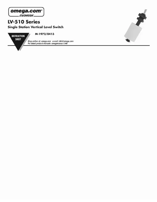
1INTRODUCTION Step OneSpecifications:Accuracy: ± 5 mm in water Repeatability: ± 2 mm in waterExtreme orientation: ±20° from verticalSpecific Gravity: 0.8 minimumContact type: (1) SPST (reed)Contact rating: 50 VA @ 0.5AContact output: Selectable NO or NC Temperature range: F: ‐40° to 176° / C: ‐40° to 80° Pressure: 10 psi (0.7 bar)Sensor rating: NEMA 6 (IP68)Sensor material: LV‐510: PolypropyleneLV‐511: Polyvinylidene Fluoride Wire jacket material: LV‐510: PVCLV‐511: TFEWire type: 2‐conductorWire length: 2’ (61 cm)Mounting threads: 1/8" NPTClassification: General purpose, CE Installation:1.Switches should be installed rigidly so the float orfloats are free to move as the liquid level changes.2.Switches should be mounted in a tank area freeof severe turbulence or protected from such turbulence by appropriate and adequate slosh shields.3.Vertical switch stems should be vertical for bestresults, but satisfactory operation is possible in most liquids with the stem at up to a 20° angle from vertical.4.Care should be taken that switches are alwaysoperated within electrical ratings.5.Orientation for switches can be changed fromnormally open to normally closed dry or vice versa by removing the float and reversing it in the stem.Dimensions:Components:Part NumberBodyMaterialCableMaterialThreadLV‐510 PP PVC 1/8” NPT LV‐511 PVDF TFE 1/8” NPT Switch Rating:Reed Switch Rating Max. Resistive Load VA Volts Amps (AC) Amps (DC)500‐50 0.5 0.5120 0.4 0.4240 0.2 0.2Top Wall Installation: Omega Engineering LV‐510 series switch may be installed through the top wall of a tank. Because the thread of the sensor is very small (1/8”), finding standard fittings may be difficult. In lieu of standard fittings, one suggestion is to use a larger pipe, such as ½”. Place a cap or plug on the end of the pipe and tap a 1/8” thread into the end. Secure the other end of the pipe to the top of the tank or to a clamp. For pipes longer than 2’, be sure to cleanly extend the cable (splice) so that the connection is not exposed to the liquid.23ELECTRICAL Step TwoSignal Outputs (Normally Open vs. Normally Closed): The LV ‐510 series float switch ships from the factory in the Normally Open (NO) configuration. The normal state is when the float is resting on the bottom of the stem. An orientation mark will appear on the top of the float when it is in the NO configuration. To switch the LV ‐510 series from NO to NC configuration, flow the steps below.1. Remove the C ‐clip from the stem.2. Remove the float and rotate it 180°.3. Return the float to the stem with orientation mark now on the bottom.4. Replace the C ‐clip. Normally Open Operation :Normally ClosedOperation :Orientation mark on the top of the float. In the dry state, the float rests on the bottom of the stem and the circuit is open.Orientation mark on the bottom of the float. In the dry state, the float rests on the bottom of the stem and the circuit is closed.As the switch becomes wet, the float becomes buoyant and circuit closes.As the switch becomes wet, the float becomes buoyant and circuit opens.Contact Protection (Reed Switch): When current is interrupted, the inductance of the load generates a high frequency voltage, which appears across the switch contacts. If the voltage is large enough, it can cause arcing. Arcing can cause the contacts to weld to each other resulting in unreliable switching performance. It is essential to protect the circuit, by suppressing the voltage to prevent arcing. This can be accomplished through the use of a diode for DC circuits and a resistor ‐capacitor network for AC circuits. DC Contact Protection:AC Contact Protection:4。
液位计操作方法说明书一、简介液位计是一种用于测量液体高度的设备,通常用于工业生产和实验室等领域。
本操作方法说明书旨在向操作人员介绍如何正确操作液位计,以便准确测量液体的高度。
二、操作前准备1. 检查液位计的外观是否完好无损,确保仪器无任何损坏。
2. 确保仪器已正确安装并连接到所需设备或容器。
3. 根据实际需求,选择和设置合适的仪器参数,如量程范围和单位。
三、操作步骤以下是液位计的基本操作步骤,应根据实际情况进行适当调整:1. 打开电源使用指定电源连接液位计,并确保电源供应稳定。
打开电源开关,仪器开始工作。
2. 启动仪器按下启动按钮或者根据仪器说明书中的具体操作要求进行操作,启动液位计。
3. 校准仪器在开始测量前,应进行仪器校准。
校准液位计旨在确保仪器的准确性,并消除任何可能的误差。
校准方法可以根据具体型号和品牌的要求进行。
4. 执行测量将液体缓慢倒入待测容器,同时观察液位计读数的变化。
在液面稳定后,记录读数并停止倒液。
确保读数的准确性和稳定性。
5. 停止仪器当测量完成后,根据仪器说明书中的具体要求,停止液位计的工作。
6. 关闭电源关闭电源开关,断开液位计与电源的连接。
四、注意事项1. 操作人员在使用液位计前,应熟悉仪器的操作说明书,并按照说明书中的操作步骤进行操作。
2. 在操作过程中,请保持仪器周围的环境安静和干燥,以免影响液位计的测量精度。
3. 如果遇到任何故障或异常情况,请立即停止操作,并联系维修人员进行排查和修复。
4. 定期对液位计进行维护和保养,以确保其良好的工作状态。
5. 操作人员应时刻保持警惕,防止操作中发生意外事故。
五、常见故障及排除方法以下是一些常见故障及其可能的排除方法,仅供参考:1. 仪器无法启动- 检查仪器是否连接到正确的电源,并确保电源供应正常。
- 检查仪器连接是否牢固,并排除任何可能的松动或损坏。
2. 仪器读数异常或不稳定- 检查液位计是否正确校准,是否存在误差或偏移。
gt2-71n中文使用说明书
基恩士AUTOIDNAVIGATOR怎么使用
KEYENCE基恩士GT-H10位移传感器,配GT-71(GT-71A为NPN型)光纤放大器其输出工作原理图如下:输出开关量点PLC可以通过I/O 输入点接收,如果PLC需要采集其精确定位数据信号,则还需要配
DL-RS1A通讯模块,此模块与PLC之间用RS...
基恩士激光位移传感器怎样输出数据
——有0~20mA,0~5V模拟信号输出,配合通用的数采转换成数
字信号就可以了.
基恩士激光位移传感器LK - G5000与LK - G5001有什么区别除了精度外没有区别,LK-G5000是日本国内应用的,Lk-G5001是针对海外销售的.
位移传感器的作用是什么?都有哪些型号?
位移传感器又称为线性传感器,是一种属于金属感应的线性器件,传感器的作用是把各种被测物理量转换为电量.在生产过程中,位移
的测量一般分为测量实物尺寸和机械...
有激光类型的微米位移传感器吗? -
有的传感器(英文名称:transducer/sensor)是一种检测装置,
能感受到被测量的信息,并能将感受到的信息,按一定规律变换成为
电信号或其他所需形式的信息输出,以满足信息的传输、处理、存储、显示、记录和控制等要求.传感器的特点包括:微型化、数字化、智能化、多功能化、系统化、网络化.它是实现自动检测和自动控制的首
要环节.传感器的存在和发展,让物体有了触觉、味觉和嗅觉等感官,让物体慢慢变得活了起来.通常根据其基本感知功能分为热敏元件、光敏元件、气敏元件、力敏元件、磁敏元件、湿敏元件、声敏元件、放射线敏感元件、色敏元件和味敏元件等十大类.。
n ec t e q u i p m e n t u n l e s s p o w e r h a s b e e n s w i t c h ed o ff o r t he a r e a i s n o th a z a r d o u s .T h e a c c e s s o r i e s f o r p i p e c o n n e c t i o n s a n d t h e a p p r o p r i a t e g a s k e t s a n d s e a l i n g r i n g sa r e n o t s u p p l i e d w i t h t h e s e n s o r s . T h e s e a r e t h e c u s t o m e r ’s r e s p o n s ib i l i t y .D e p e n d i n g o n t e m p e r a t u r e a n d p r e s s u r e o p e r a t i n gc o nd i t i o n s , t he g a s k e t s , t h es e a l i n g a n d t h e a p p l i c a b l e t o r q u e s m u s t b e s e l e c t e d b y t h e u s e r .F o r f u r t h e r i n f o r m a t i o n r e g a r d i n g c o n n e c t i o n s , p l e a s e r e f e r t o t h e c o r r e s p o n d i n gS t a n d a r d s .I n s t a l l a t i o n a n d o p e r a t i o nT h e u n i t i s c o n s t r u c t e d u s i n g t h e m o s t u p t o d a t e p r o d u c t i o n e q u i p m e n t a n d c o m p l i e s w i t h t h e s a f e t y r e q u i r e m e n t s o f t h e l o c a l g u i d e l i n e s . H o w e v e r , i f i t i s i n s t a l l e d i n c o r r e c t l y o r m i s u s e d , c e r t a i n a p p l i c a t i o n d a n g e r s c a n o c c u r . I n s t a l l a t i o n ,w i r i n g a n d m a i n t e n a n c e o f t h e u n i t m u s t o n l y b e c o m p l e t e d b y t r a i n e d , s k i l l e d p e r s o n n e l w h o a r e a u t h o r i z e d t o d o s o b y t h e p l a n t o p e r a t o r . T h e p l a n t o p e r a t o r m u s t m a k e s u r e t h a t t h e m e a s u r e m e n t s y s t e m h a s b e e n c o r r e c t l y w i r e d t o t h ec o n n e c t i o n s c h e m a t i c s . P r o c ed u re s i n d i c a t e d i n t h e s e i n s t r u c t i o n s m u s t b ef o l l o w e d .R e t u r n sP l e a s e f o l l o w t h e R e t u r n A u t h o r i z a t i o n P o l i c y w h i c h i s a t t a c h e d w i t h t h i s m a n u a l .S a f e t y p i c t o g r a m s a n d s y m b o l ss d r a w a t t e n t i o n t o a c t i v i t i e s o r p r o c e d u r e s t h a t c a n h a v e a d i r e c t i n fl u e n c e o n o p e r a t i o n o r t r i g g e r a n u n f o r e s e e n d e v i c e r e a c t i o n i f t h e y a r e n o t c a r r i e d o u tp r o p e r l y . a t t e n t i o n t o a c t i v i t i e s o r p r o c e d u r e s t h a t c a n l e a d t o p e r s o n s b e i n g s e r i o u s l y i n j u r e d , t o s a f e t y r i s k s o r t o t h e d e s t r u c t i o n o f t h e d e v i c e i f t h e y a r e n o tc a r r i ed o u t p r o pe r l y .T h o u g h t h e i n f o r m a t i o n p r o v i d e d h e r e i n i s b e l i e v e d t o b e a c c u r a t e , b e a d v i s e d t h a t t h e i n f o r m a t i o n c o n t a i n e dh e r e i n i s N O T a g u a r a n t e e o fs a t i s f a c t or yr e s u l t s . S p e c i fi c a l l y , t h i s i n f o r m a t i o n i s n e i t h e r a w a r r a n t y n o r g u a r a n t e e , e x p r e s s e d o r i m p l i e d , r e g a r d i n g p e r f o r m a n c e ; m e r c h a n t a b i l i t y , fi t n e s s , o r o t h e r m a t t e r w i t h r e s p e c tt o t h e p r o d u c t s ; a n d r e c o m m e n d a t i o n f o r t h e u s e o f t h e p r o d u c t /p r o c e s s i n f o r m a t i o n i n c o n fl i c t w i t h a n y p a t e n t . P l e a s e n o t e t h a t E n d r e s s +H a u s e r r e s e r v e s t h e r i g h t t o c h a n g e a n d /o r i m p r o v e t h e p r o d u c t d e s i g n a n ds p e c i fi c a t i o n s w i t h o u t n o t i c e .Compact Instructions RTD Assembly TH15Measuring SystemRTD assembly TH15 with spring loaded insert.The Pt100 RTD is specifically designed for use in two different process temperature ranges:Low range RTD -58 °F to 392 °F; high range RTD -328 °F to 1112 °F.Performance Characteristics (continued)Maximum measured error (Pt100 / IEC 60751)Classmax. Tolerances (°C)A ± (0.15 + 0.002 · |t|*), temperature range: -100 °C to 450 °CB ± (0.3 + 0.005 · |t|*), temperature range: -200 °C to 600 °C * |t| = absolute value °C. For measurement errors in °F, calculate using equation above in °C, then multiply the outcome by 1.8.Insulation resistance Insulation resistance between terminals and probe sheath, test voltage 250 V. • ≥ 100 MΩ at 77 °F (25 °C)• ≥ 10 MΩ at 572 °F (300 °C)Supplementary documentationAll important Temperature Operating Instructions, particularly with regard to head and field transmitters are available on CD–ROM, find enclosed or order by order number: SONDTT-AG .I m p o r t a n t N o t i c ec k c o u ld c a u se d e a t h o r s e r i o u s i n j u r y . If t h e s e n s o r i s i n s t a l l e d i n a h igh v o l t a g e e n vi r o n m e n t a n d a f a u l t o r i n s t a l l a t i o n e r r o r o c c u r s , h i g h v o l t a g e m a yb e p r e s e n t o n t h ec o n n e c t i o n t e r m i n a l s o r t h e p r o b e i t s e l f .S a f e a nd se c u r e o p e r a t i o n of t h e t e m p e r a t u r e s e n s o r c a n o n l y b eg u a r a n t e e d i f th e o p e r a ti n g i n s t r u c t i o n s o f t h e u s e d t r a n s m i t t e r s a n d a l l i n c l u d e d s a f e t y n o t e s a r e r e a d , u n d e r s t o o d a n d f o l l o w e d . F o r E n d r e s s +H a u s e r t e m p e r a t u r e t r a n s m i t t e r s s e ee n c l o s e d C D –R O M .C o r r e c t u s eT h e m a n u f a c t u r e r c a n n o t b e h e l d r e s p o n s i b l e f o r d a m a g e c a u s e d b y m i s u s e o f t h e u n i t . T h e i n s t a l l a t i o n c o n d i t i o n s a n d c o n n e c t i o n v a l u e s i n d i c a t e d i n t h e o p e r a t i n gi n s t r u c t i o n s m u s t b e f o l l o w e d !m b l y (T H 15) i s d e s i g n e d t o b e u s e d i n c o n j u n c t i o n w i t h a t h e r m o w e l l . I t i s n o t m e a n t t o b e u s e d d i r e c t l y i n p r e s s u r i z e d a p p l i c a t i o n s ;M a x i m u m w o r k i n g p r e s s u r e = P a t m . (A t m o s p h e r i c p r e s s u r e )I n s t a l l a t i o n G u i d e l i n e s a n d S a f e t y i n s t r u c t i o n s1. I n s t a l l t h e u n i t a c c o r d i n g t o t h e r e l e v a n t N E C C o d e a n d l o c a l r e g u l a t i o n s .2. A v o i d a n y s p a r k d u e t o i m p a c t , f r i c t i o n a n d i n s t a l l a t i o n . A n t i -s p a r k i n gw r e n c h e s s h o u l d b e u t i l i z e d .3. T h e t e m p e r a t u r e s e n s o r s h o u l d b e c o n n e c t e d t o t h e p o w e r s u p p l y o r o t h e re x t e r n a l c i r c u i t u s i n g t h e a p p r o p r i a t e c a b l e g l a n d s a n d w i r e e n t r i e s .4. F o r a m b i e n t t e m p e r a t u r e h i g h e r t h a n 158 °F , s u i t a b l e c a b l e s , c o n d u i t a n dc o nd u c t o r s m u s t be u s e d . O n l y u s e a p p r o v e d w i r e e n t r i e s .5. W h e n u t i l i z e d i n d u s t a t m o s p h e r e s , t h e c o n n e c t i o n b e t w e e n t h e h o u s i n g ,fi t t i n g s a n d t h e r m o w e l l s h o u l d p r o v i d e a m i n i m u m d e g r e e o f I n g r e s s P r o t e c t i o n . L i q u i d /g a s s e a l a n t s s h o u l d b e u s e d . L o c a l r e g u l a t i o n s n e e d t o b er e s p e c t e d .KA00195R/24/EN/13.1271207990DimensionsX A = Immersion length RTD sensor = thermowell drilled depth (see table)X = Insert overall length (X = X A + E)For spare part insert, TU111, please contact Endress+Hauser! InstallationExamples of spring loaded insert installation.A: RTD assembly TH15 installed within a socket weld thermowellB: RTD assembly TH15 installed within a tilted installed threaded thermowell C: RTD assembly TH15 installed within a flanged thermowellFor installation proceed as follows:1. Seal the extension nipples with TFE tape before screwing in the device.2. Screw the RTD assembly TH15 only into an already prepared thermowell.container wall. Otherwise it could cause death or serious injury!Electrical connection-wiring diagramsThe blocks and transmitters are shown as they will sit inside the heads in reference to the conduit opening. ALWAYS terminate leads to the outside screw!Wire specifications 24AWG, 19 strand silver plated copper with 0.010” TFE extruded outerRecommended minimum immersionConstructionRTD insert ø¼”High temperature range -328 °F to 1112 °F (-200 °C to 600 °C) 1 ¼”Low temperature range -58 °F to 392 °F (-50 °C to 200 °C)¾”Technical dataWeight From 1 to 5.5 lbs Material Insert 316 SSShock and vibration resistance 4g/2 to 150 Hz as per IEC 60 068-2-6Ambient temperature limits*Housing without head-mounted transmitter Aluminium pressure die-cast housing -40 to 300 °F (-40 to 150 °C)Plastic housing-40 to 185 °F (-40 to 85 °C)Deep drawn SS housing without display -40 to 300 °F (-40 to 150 °C)Housing with head-mounted transmitter -40 to 185 °F (-40 to 85 °C)Deep drawn SS housing with display -4 to 160 °F (-20 to 70 °C)Field transmitter with display -40 to 158 °F (-40 to 70 °C)without display-40 to 185 °F (-40 to 85 °C)*For hazardous areas refer to the transmitter control drawingPerformance CharacteristicsResponse time63% response time per ASTM E644Construction RTD insert ø ¼”High temp. range 3 s Low temp. range9 sResponse time for sensor assembly without thermowell and transmitter!。
液位传感器的使用方法液位传感器是一种常见的工业检测装置,它可以测量液体的高度或者浓度,是许多行业中必不可少的设备。
本文将探讨液位传感器的基本原理、使用方法以及一些注意事项。
液位传感器的基本原理是利用物理传感器来测量液体的高度或密度。
它的工作原理可以分为两种主要类型:浮子式和压力式。
浮子式液位传感器是通过悬浮在液体中的球体或浮子来测量液位的高度。
当液体的液位上升或下降时,浮子会随之移动,改变电路的导通或截断,从而传递液位信息。
压力式液位传感器则是通过测量液体对传感器的压力来确定液位高低。
当液位上升时,液体的压力也会增加,传感器会将压力信号转换成电信号,从而获得液位数据。
在使用液位传感器之前,首先需要确定传感器的安装位置。
这个位置应该在液体容器的一侧,以确保传感器能够准确测量到液体的高度。
在安装过程中,要确保传感器与液体之间没有任何障碍物,以免影响传感器的测量精度。
液位传感器的使用方法相对简单,但在实际应用中还是需要注意一些事项。
首先,确保传感器与液体接触的部分是干净的。
由于液体中可能存在杂质或污垢,长期接触可能会导致传感器故障或精度下降。
因此,定期清洁传感器是必要的。
其次,根据传感器的技术规格,严格控制液位的测量范围。
超出传感器的工作范围可能会损坏传感器或导致误差较大的测量结果。
此外,液位传感器在测量液体高度时,需要考虑到液体的特性,如液体的粘度、温度等。
这些因素可能会影响传感器的测量结果,因此需要进行适当的修正。
液位传感器在各个行业中都有广泛的应用。
在化工行业中,液位传感器可以用于监测和控制反应釜中液体的高度,确保化学反应过程的安全和稳定性。
在食品行业中,液位传感器可以用于检测糖浆或果汁的浓度,以确保产品的质量一致性。
在水处理工程中,液位传感器可以用于监测水池或水箱中的水位,及时控制供水量等。
总结而言,液位传感器是一种重要的工业检测装置,它可以通过测量液体的高度或密度来提供有价值的信息。
在使用液位传感器时,应注意传感器的安装位置、定期清洁以及适当修正测量结果。
电容式油位传感器特别声明:对于使用24v车载电源的客户,请在电源链接处连接自恢复保险。
如果电源正负极取自电瓶,请在电瓶正负极出口处同时加装自恢复保险。
检测及安装时,请注意引出线的线序。
传感器属于精密检测设备,用户不可私自拆解传感器。
对于客户私自拆解的我公司将不再负责售后。
针对快递市场的现状,为更好保护采购与销售的双方利益。
我们建议购买传感器的请客户对所采购需快递的传感器保价。
如客户不选择保价出现产品在运输途中丢失损坏,本公司概不负责。
请客户在接收到快递时,首先打开包装确认货品数量以及有无外观上的损坏后再签收。
请客户在接收到产品后2-5天内做好产品性能测试工作,过期本公司将只对产品进行维修处理。
前言:电容式液位传感器基于精密电子测量方案的拓展应用,采用多通道比例式采集系统。
传感器可自动识别被测介质的各种参数,系统可对各种动态变化的采集数据分析处理,是真正意义上的高智能传感器。
传感器可以安装于任何需要测量液位的非粘性容器上,实现高精度智能化测量。
产品特点:1.传感器壳体采用优质不锈钢制造,无可动检测部件整体设计紧凑,测量部无任何可动及弹性元器件,具有抗高空跌落、抗摔打、抗震动等优点。
2.输出信号可随液位高度变化而无梯度连续变化。
3.传感器采用航天级元器件,全数字化采集、处理。
对于数字输出的传感器是一款完全数字传感器。
4.传感器在设计上解决了温度以及不同被测介质对传感器精度的影响,传感器适应于不同介电常数物质的测量,传感器具有自动校准自动识别被测介质的能力,被测介质发生变化时(不同型号油品、不同地区油品)传感器可以自动识别补偿,从而实现了传感器的高智能化。
5.供电电压适合市场需求,供电电压范围18-35V。
6.传感器整机功耗仅为25mw(12V),可以长期工作在电池供电系统中。
7.传感器具有极高的抗干扰能力,可耐受人体、大功率对讲设备、大功率电器的启停以及高电压冲击。
8.传感器具有极高的分辨率,1米长的传感器检测水时,其分辨率可以达到5PPM。
基恩士液位传感器说明书
1、液位传感器(静压液位计/液位计/液位变送器/液位传感器/水位传感器)是一种测量液位的压力传感器.静压投入式液位变送器(液位计)是基于所测液体静压与该液体的高度成比例的原理。
2、采用国外先进的隔离型扩散硅敏感元件或陶瓷电容压力敏感传感器,液位传感器将静压转换为电信号,液位传感器再经过温度补偿和线性修正,液位传感器转化成标准电信号(一般为4~
20mA/1~5VDC)。
3、液位传感器静压投入式液位变送器(液位计)适用于石油化工、冶金、电力、制药、供排水、液位传感器环保等系统和行业的各种介质的液位测量。
精巧的结构,液位传感器简单的调校和灵活的安装方式为用户轻松地使用提供了方便。
4~20mA、0~5v、0~10mA等标准信号输出方式根据需要任选。