九九物联AFW121Tx CN V2.0数据手册
- 格式:pdf
- 大小:13.47 MB
- 文档页数:21
BM18规格书版本:V1.0更新日期:2021年07月02日深圳市易连物联网有限公司版权所有本产品的规格书如有变更,恕不另行通知。
深圳市易连物联网有限公司保留在不另行通知的情况下,对其中所包含的规格书和材料进行更改的权利,同时由于信任所引用的材料所造成的损害(包括结果性损害),包括但不限于印刷上的错误和其他与此出版物相关的错误,易连物联网公司将不承担责任。
深圳市易连物联网有限公司-1-修改记录文档版本作者审核人发布日期修改说明V1.0罗贤丽朱志林2020/7/2 1.初稿深圳市易连物联网有限公司-2-目录修改记录 (2)目录 (3)1.概述 (5)1.1产品概述 (5)1.2特点 (5)1.3应用领域 (5)2模块封装接口 (6)2.1引脚描述图 (6)2.2模块引脚描述 (6)2.3机械尺寸 (7)2.4实物图(正面、背面) (8)3电气参数 (9)3.1绝对电气参数 (9)3.2工作条件 (9)3.3功耗(功耗附图) (9)4射频特性 (11)4.1基本射频特征 (11)4.2RF输出功率 (11)4.3RF接收灵敏度 (12)5天线信息 (12)5.1天线类型 (12)5.2降低天线干扰 (12)6硬件参考设计 (12)6.1典型应用图 (12)6.2设计说明 (13)7通讯协议 (13)7.1说明 (13)7.2通用透传 (13)7.3AiLink协议 (13)7.4好身材协议 (14)7.5其他定制协议 (14)8生产指导 (14)8.1出货包装 (14)深圳市易连物联网有限公司-3-8.2工艺事项 (15)8.3生产测试 (15)9联系我们 (16)深圳市易连物联网有限公司-4-1.概述1.1产品概述BM18是深圳市易连物联网有限公司专为智能无线数据传输而打造,采用T2芯片,遵循蓝牙5.0蓝牙规范。
可以按照客户的要求定制协议,满足多场景用途。
1.2特点●蓝牙V5.0●内置PCB射频天线●内置FLASH:2Mbit● 2.3_3.3V宽输入电压范围1.3应用领域该模块主要用于短距离的数据无线传输领域。

WT32-ETH01DATASHEETVersion1.123October,2019Disclaimer and Copyright NoticeInformation in this paper,including URL references,is subject to change without prior notice.This document is provided“as is”with no warranties whatsoever,including any warranty of merchantability, non-infringement,fitness for any particular purpose,or any warranty otherwise arising out of any proposal, specification or sample.All liability,including liability for infringement of any patent rights,relating to use of information in this document is disclaimed.No licenses,either express or implied,by estoppel or otherwise,to any intellectual property rights are granted herein.The Wi-Fi Alliance Member logo is a trademark of the Wi-Fi Alliance.All trade names,trademarks and registered trademarks mentioned in this document are property of their respective owners,and are hereby acknowledged.Revision HistoryContentsWT32-ETH01 (1)1.Overview (6)2.Features (6)3.Hardware Specifications (8)3.1System Block Diagram (8)3.2Product Images (8)3.3Pin Descriptions (9)3.4Power Supply Characteristics (10)3.4.1Supply Voltage (10)3.4.2Power Supply Modes (10)4.Instructions (11)4.1Power-on Instruction (11)4.2Indicator Instruction (11)4.3Usage Instruction (11)4.4Network Port Indicator Instruction (11)5.Interface Descriptions (12)6.Product Functions (12)6.1Default parameters (12)6.2Basic Functions (13)6.2.1Set IP/Subnet Mask/Gateway (13)6.2.2Restore Factory Settings (13)6.2.3Firmware upgrades (14)6.2.4AT Command Function Settings (14)6.2.5Data Transmission Function (14)6.3Socket Function (14)6.3.1TCP Client (14)6.3.2TCP Server (15)6.3.3UDP Client (15)6.3.4UDP Server (15)6.4Serial Port Function (15)6.4.1At Command Settings (15)6.5Bluetooth Function (15)6.5.1Bluetooth Data Transmission (15)6.6Wifi Function (16)6.6.1Internet Access (16)6.7Cable Network Access Function (16)6.7.1Internet Access (16)1.OverviewWT32-ETH01is an embedded serial port to Ethernet module based on ESP32series launched by Wireless-Tag Technology Co.Limited.Integrating an optimized TCP/IP protocol stack,it makes it easy for users to accomplish the network access of embedded devices and greatly reduces the development time cost.Moreover,the module is designed to be compatible with half pads and through-hole connectors.As the board width of it is the generic width,the module can be directly welded to boards,or connectors,or even breadboards,which is convenient for users to apply in different scenes.Esp32series IC is the SOC integrated with2.4GHz Wi-Fi and Bluetooth dual modes,with ultra-high RF performance,stability,versatility,reliability,and ultra-low power consumption.2.FeaturesTable1:Product specificationsCategory Items Product specificationsWi-Fi RF certifications FCC/CE/RoHSProtocols802.11b/g/n/e/i(802.11n,Up to150Mbps)A-MPDU and A-MSDU aggregation,0.4_s guardinterval supportFrequency range 2.4~2.5GHzBluetooth Protocols Bluetooth v4.2BR/EDR and BLE standards Radio NZIF receiver with-97dBm sensitivityHardware Network portspecificationsRJ45,10/100Mbps,Cross-direct connection adaptive Serial baud rate80~5000000On-board flash32MbitOperatingvoltage5V or3.3VOperatingcurrentAverage:80mASupply current Minimum:500mAOperatingtemperature-40°C~+85°CAmbienttemperatureNormal temperaturePackaging Half pad/Through-hole connector(Optional)SoftwareWi-Fi mode Station/softAP/SoftAP+station/P2PWi-Fi securitymechanismsWPA/WPA2/WPA2-Enterprise/WPS Encryption types AES/RSA/ECC/SHAFirmwareupdateRemote OTA upgrade via network SoftwaredevelopmentSDK used for further development NetworkingprotocolIPv4、TCP/UDPIP accessmethodsStatic IP、DHCP(Default)Transparenttransmission modesTCP Server/TCP Client/UDP Server/UDP Client UserconfigurationsAT+commands set3.Hardware Specifications3.1System Block DiagramFigure1:System Block Diagram 3.2Product ImagesFigure2:Product Images3.3Pin DescriptionsTable1:Debugging/Burning InterfacesPin Name Description1EN1Reserved debugging/burning interface;Active-high enable2GND Reserved debugging/burning interface;GND33V3Reserved debugging/burning interface;3V34TXD Reserved debugging/burning interface;IO1,TXD05RXD Reserved debugging/burning interface;IO3,RXD06IO0Reserved debugging/burning interface;IO0Table2:IO DescriptionsPin Name Description1EN1Active-high enable2CFG IO32,CFG3485_EN IO33,RS485Enable pin4RXD IO5,RXD25TXD IO17,TXD26GND GND73V323V3Power supply8GND GND95V25V Power supply10LINK Network connection indicator pin11GND GND12IO393IO39,Input only13IO363IO36,Input only14IO15IO1515I014IO1416IO12IO1217IO35IO35,Input only18IO4IO419IO2IO220GND GNDNote1:The module enables high level by default.Note2:Power supply makes a binary choice between3V3and5V.Note3:IO39,IO35and IO36only support input.3.4Power Supply Characteristics3.4.1Supply VoltageYou can make a binary choice between3V3and5V for power supply voltage of the module.3.4.2Power Supply ModesUsers can choose from the following modes flexibly according to their needs:1)Through hole(Welding pins):Power supply with Dupont line connection;●Power supply with breadboard connection;2)Half pad(Directly welded to the board):Power supply of user board.4.Instructions4.1Power-on InstructionIf the Dupont line connection is used:Find the3V3or5V power input port,and connect the corresponding voltage to it;when LED1indicator lights up,it indicates that power is on.4.2Indicator Instruction●LED1:Power light,when the power supply is normal,the indicator light is on;●LED3:Serial port indicator,RXD2(IO5)When there is data flow,the indicator light is on;●LED4:Serial port indicator,TXD2(IO17)When there is data flow,the indicator light is on;4.3Usage InstructionUsers can choose from three ways of use according to their needs:1)Through hole(Welding pins):Dupont line connection;2)Through hole(Welding pins):breadboard connection;3)Half pad:Users can directly weld the module on their own board.4.4Network Port Indicator InstructionTable3:Network Port Indicator DescriptionsNetwork PortIndicatorFunction DescriptionGreen Indicator Connection statusindicationwhen properly connected to the network,the green light is on.Yellow Indicator Data indication The indicator flashes when the module receives or sends data, including receiving network broadcast package.5.Interface Descriptions6.Product Functions6.1Default parameters ItemsDescriptions Port Baud Rate115200Serial port parametersNone/8/1Transparent Transmission Channel Serial to Ethernet transparenttransmission channel6.2Basic Functions6.2.1Set IP/Subnet Mask/Gateway1.IP address is the identity representation of the module in the LAN,which is unique in the LAN,so it can not be repeated with other devices in the same LAN.There are two ways to obtain the IP address of the module:static IP and DHCP/dynamic IP.a.Static IPStatic IP needs to be set manually by the user.In the process of setting,attention should be paid to write IP, subnet mask and gateway at the same time.Static IP is suitable for scenarios where IP and devices need to be counted and correspond to each other.You should pay attention to the correspondence of IP address,subnet mask and gateway when setting.To use static IP,you need to set each module and ensure that the IP address is not repeated with other network devices in the LAN.b.DHCP/Dynamic IPThe main function of DHCP/Dynamic IP is to dynamically obtain IP address,gateway address,DNS server address and other information from the gateway host,so as to avoid the tedious steps of setting IP address.It is applicable to scenarios where there is no requirement for IP,and it is not required to have a one-to-one correspondence between IP and module.Note:The module cannot be set to DHCP when directly connected to the computer.Generally,the computer does not have the ability to assign IP addresses.If the module is set as DHCP directly connected to the computer,it will cause the module to be in the state of waiting for IP address allocation all the time,which will cause the module to fail to perform normal transmission.The module default static IP:192.168.0.72.The subnet mask is mainly used to determine the network number and host number of the IP address,indicate the number of subnets,and determine whether the module is in the subnet.The subnet mask must be set properly.The commonly used class C subnet mask is255.255.255.0.The network number is the first24bits,the host number is the last8bits,and the number of subnets is255.If the module IP is within the range of255,it is considered that the module IP is in the subnet.3.Gateway refers to the network number of the current IP address of the module.If the module connects to the external network by accessing devices such as routers,the gateway is the IP address of the router.If the setting is wrong,the external network cannot be connected correctly.If you do not connect to devices such as routers, you do not need to set it.It’s OK by default.6.2.2Restore Factory Settings1.Restore factory settings by AT command:restore factory settings via AT+RESTORE.2.Restore factory settings by hardware:CFG to ground,restart the module.6.2.3Firmware upgradesOTA remote upgrade is the way for modules to upgrade firmware,through which more application functions can be obtained.a.Firmware upgrade can be connected to the network through wired network or wifi.b.Operate GPIO2to ground,restart the module,and enter OTA upgrade mode.c.After the upgrade is completed,disconnect GPIO2from the ground,restart the module,and it enters the normal working mode.OTA firmware upgrade instructions:when the firmware is being downloaded,the serial port TXD indicator flashes quickly;when the download is being upgraded,the serial port TXD indicator is always on;when the upgrade is successful,the serial port TXD and RXD indicators are always on;when the upgrade fails,the serial port TXD indicator flashes slowly.6.2.4AT Command Function SettingsUsers can set functions of the module by inputting AT commands through serial ports.Refer to the ESP32AT instruction set for details.6.2.5Data Transmission FunctionThe module has four data transmission ports:Serial port,Wifi,Ethernet and Bluetooth.Users can use AT commands to combine the four data ports in pairs for data transmission.Use AT+PASSCHANNEL command to set/query the module's transparent transmission channel.After the setting is complete,the module needs to be restarted to take effect.6.3Socket FunctionThe Socket working mode of the module is divided into four types:TCP Client,TCP Server,UDP Client,and UDP Server,which can be set by AT command.For AT command operation,please refer to esp32wired module AT command routine v1.2.6.3.1TCP Client1.TCP Client provides client connection for TCP network services.It initiates connection request and establish connection to the server to realize the interaction between serial port data and server data.According to the relevant provisions of TCP protocol,TCP client has the difference between connection and disconnection,so as to ensure the reliable exchange of ually used for data interaction between devices and servers,it is the most common way of networking communication.2.When the module connects TCP server as a TCP client,it needs to pay attention to the parameters such as the target IP/domain name and the target port number.Target IP can be of a local device in the same LAN.It canalso be an IP address from a different LAN or an IP address across the public network.If connecting to a server across the public network,the server is required to have a public IP.6.3.2TCP ServerIt is usually used for communication with TCP client in LAN.It is suitable for the scenario where there is no server in the LAN and there are multiple computers or mobile phones requesting data from the server.The same as TCP Client,TCP server has the difference between connection and disconnection to ensure reliable exchange of data.6.3.3UDP ClientUDP Client is a connectionless transport protocol,providing transaction-oriented simple and unreliable information transmission services.There is no connection establishment or disconnection,and data can be sent to each other only by specifying IP and port.It is usually used in data transmission scenarios where there is no requirement for the packet loss rate,the data packets are small and the transmission frequency is relatively fast, and the data is transferred to the specified IP.6.3.4UDP ServerUDP Server means that the source IP address is not verified on the basis of ordinary UDP.After receiving a UDP packet,the destination IP is changed to the data source IP and port number.When sending data,send it to the IP and port number of the most recent communicationThis mode is usually used in data transmission scenarios where multiple network devices need to communicate with the module and do not want to use TCP due to the high speed and frequency.6.4Serial Port Function6.4.1At Command SettingsUsers can input AT commands through serial ports to set functions for a module.6.4.2Transmitting Serial DataThe user makes the module enter the data transmission mode through AT command.The module can directly transfer serial port data to the corresponding data transmission end(wifi,Ethernet or Bluetooth)through the set passthrough channel.6.5Bluetooth Function6.5.1Bluetooth Data TransmissionThrough the existing Bluetooth function of the module,the module can obtain Bluetooth data,and through the set pass-through channel,the Bluetooth data can be directly transferred to the corresponding data transmission end(wifi,Ethernet or serial port).6.6Wifi Function6.6.1Internet AccessThe module wifi is connected to the Internet or LAN through a router.The user configures the socket function through the AT command.The module can establish a TCP/UDP connection and then access the user's designated server.6.7Cable Network Access FunctionStable network connection can be obtained through wired network to ensure stable network data acquisition.6.7.1Internet AccessThe module is connected to the Internet or LAN through a wired network.The user configures the socket function through the AT command.The module can establish a TCP/UDP connection and then access the user's designated server.。
版本: 1.3 日期: 2021-12-30© 2013 – 2021 AutoChips Inc.本文档包含杰发科技的专有信息。
未经授权,严禁复制或披露本文档包含的任何信息。
本文档如有更改,不另行通知。
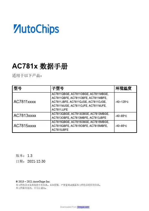
AC781x 数据手册适用于以下产品:型号 子型号环境温度AC7811xxxx AC7811QBGE, AC7811OBGE, AC7811MBGE,AC7811QBFE, AC7811OBFE, AC7811MBFE, AC7811JBFE, AC7811QJGE, AC7811OJGE, AC7811MJGE, AC7811OJFE, AC7811MJFE, AC7811JJFE-40~125°CAC7813xxxx AC7813QBGE, AC7813OBGE, AC7813MBGE, AC7813OBFE, AC7813MBFE, AC7813JBFE -40~85°C AC7815xxxx AC7815QBGE, AC7815OBGE, AC7815MBGE, AC7815QBFE, AC7815OBFE, AC7815MBFE, AC7815JBFE-40~85°C修订记录文档目录修订记录 (2)文档目录 (3)1主要特性 (5)2器件标识 (6)2.1说明 (6)2.2格式 (6)2.3字段 (6)2.4示例 (6)3参数分类 (7)4额定值 (8)4.1热学操作额定值 (8)4.2湿度操作额定值 (8)4.3ESD 操作额定值 (8)4.4电压和电流操作额定值 (9)5通用 (10)5.1静态电气规格 (10)5.1.1电源和地引脚 (10)5.1.2DC 特性 (10)5.1.3电源电流特性 (13)5.2动态规格 (14)5.2.1控制时序 (14)5.2.2PWM模块时序 (15)5.3热规格 (16)5.3.1热特性 (16)6外设工作要求和行为 (18)6.1内核模块 (18)6.1.1SWD 电气规格 (18)6.2外部振荡器 (OSC) 和 ICS 特性 (18)6.2.1外部振荡器(OSC) 特性 (18)6.2.2内部RC 特性 (19)6.2.3PLL 特性 (19)6.3片内Flash 规格 (20)6.4模拟 (21)6.4.1ADC 特性 (21)6.4.2模拟比较器(ACMP)电气规格 (22)6.5通信接口 (22)6.5.1SPI 开关规格 (22)6.5.2CAN特性 (25)7尺寸 (26)7.1LQFP64封装信息 (26)7.2LQFP80封装信息 (28)8引脚分配 (30)8.1信号多路复用和引脚分配 (30)8.2器件引脚分配 (34)1主要特性∙操作特性电压范围:2.7 到5.5 V温度范围 (环境): -40 到125°C∙性能高达100 MHz的 ARM® Cortex-M3内核单周期 32位 x 32位乘法器快速I/O访问接口∙存储器和存储器接口最高256 KB的片内Flash最高 64 KB的静态随机存储器∙时钟振荡器 (Oscillator) –支持4 MHz到 30 MHz 石英晶体振荡器;可选择低功耗或高增益振荡器内部时钟源 (ICS) –内部PLL ,集成内部或外部基准时钟源, 8 MHz预校准内部基准时钟源,可用于100 MHz系统时钟内部32 kHz低功耗振荡器 (LPO)∙系统外设电源管理模块(PMC) 有三个功率模式:运行、待机和停止低压检测复位电路 (LVD)带独立时钟源的看门狗(WDOG)可编程循环冗余校验(CRC)模块串行线调试(SWD) & JTAG 接口Cortex®-M3 嵌入式跟踪宏单元™SRAM 位处理映射区域 (BIT-BAND) 1个12 通道 DMA ∙人机接口68 个通用输入输出接口 (GPIO)外部中断 (IRQ)模块∙模拟模块1个多达 16通道、12位的SAR ADC,工作在停止模式,可选硬件触发器 (ADC)2个包含6位DAC和可编程参考输入的模拟比较器(ACMP)∙定时器1个6通道脉宽调制(PWM)单元3个双通道 PWM1个8通道周期性中断定时器(TIMER)1个脉宽定时器 (PWDT)1个实时时钟 (RTC)∙通信接口2个 SPI 模块6个 UART模块(其中一路兼容Software LIN)2个I2C 模块2个CAN 模块1个硬件 LIN 模块∙封装选项80引脚 LQFP64引脚LQFP2器件标识2.1说明芯片器件型号包含可识别具体器件的字段。

UC-2100系列Arm Cortex-A8600MHz掌上型IIoT閘道器,含1個Mini PCIe無線模組擴充插槽特色與優點•Armv7Cortex-A8600-1000MHz處理器•掌上型,50x80x28公釐•Moxa工業Linux,提供10年長期支援•MXview支援集中監控設備和運算狀態•整合APIs和推式通訊,僅在需要時擷取資料•1個或2個自動感應10/100Mbps乙太網路連接埠•支援Gigabit乙太網路(UC-2112)•多達2個RS-232/422/485連接埠,可透過軟體選擇,支援所有訊號•支援Wi-Fi/行動通訊模組的Mini PCIe插槽(UC-2104)•-40至75°C的寬溫度型號符合嚴苛環境的規範認證認證簡介UC-2100系列運算平台專為嵌入式資料擷取和處理應用而設計。
電腦配備多達2個可透過軟體選擇的RS-232/422/485全訊號串列連接埠和單或雙乙太網路連接埠。
這款以Arm為基礎的掌上型運算平台系列包括多種型號,可滿足各種介面要求,例如單或雙串列和乙太網路連接埠、Gigabit乙太網路和無線連線。
這些多樣化的通訊功能可供使用者有效地將UC-2100應用在各類複雜的通訊解決方案。
UC-2100系列內建以Cortex-A8Arm為基礎的處理器,針對各種工業解決方案進行了優化。
這款小型的嵌入式電腦具備彈性的介面選項,是可靠且安全的閘道器,可協助您在現場進行資料擷取並進行處理,同時也是適用於其他許多大規模部署的實用通訊平台。
為寬溫度應用設計的型號,適合極端環境應用,例如石油和天然氣產業的應用。
此外,所有型號均使用Moxa工業級Linux平台,該平台提供優化的軟體功能和長期支援。
外觀UC-2101UC-2104UC-2111規格ComputerCPU UC-2101-LX:Armv7Cortex-A8600MHzUC-2102-LX:Armv7Cortex-A8600MHzUC-2104-LX:Armv7Cortex-A8600MHzUC-2111-LX:Armv7Cortex-A8600MHzUC-2112-LX:Armv7Cortex-A81GHzUC-2112-T-LX:Armv7Cortex-A81GHzDRAM UC-2101-LX:256MB DDR3UC-2102-LX:256MB DDR3UC-2104-LX:256MB DDR3UC-2111-LX:512MB DDR3UC-2112-LX:512MB DDR3UC-2112-T-LX:512MB DDR3Pre-installed OS Moxa Industrial Linux(Debian9,Kernel4.4)See /MILStorage Pre-installed8GB eMMCStorage Slot UC-2111-LX:Micro SD slots x1UC-2112-LX:Micro SD slots x1UC-2112-T-LX:Micro SD slots x1Computer InterfaceEthernet Ports UC-2101-LX:Auto-sensing10/100Mbps ports(RJ45connector)x1UC-2102-LX:Auto-sensing10/100Mbps ports(RJ45connector)x2UC-2104-LX:Auto-sensing10/100Mbps ports(RJ45connector)x1UC-2111-LX:Auto-sensing10/100Mbps ports(RJ45connector)x2UC-2112-LX:Auto-sensing10/100Mbps ports(RJ45connector)x1,Auto-sensing10/100/1000Mbps ports(RJ45connector)x1UC-2112-T-LX:Auto-sensing10/100Mbps ports(RJ45connector)x1,Auto-sensing10/100/1000Mbps ports(RJ45connector)x1Serial Ports UC-2101-LX:RS-232/422/485ports x1,software selectable(DB9male)UC-2111-LX:RS-232/422/485ports x2,software selectable(DB9male)UC-2112-LX:RS-232/422/485ports x2,software selectable(DB9male)UC-2112-T-LX:RS-232/422/485ports x2,software selectable(DB9male)Console Port RS-232(TxD,RxD,GND),4-pin header output(115200,n,8,1)Expansion Slots UC-2104-LX:mPCIe slot x1Cellular Antenna Connector UC-2104-LX:SMA x2Number of SIMs UC-2104-LX:1SIM Format UC-2104-LX:StandardButtons Reset button,DIP switch for serial port configurationEthernet InterfaceMagnetic Isolation Protection 1.5kV(built-in)Serial InterfaceData Bits5,6,7,8Stop Bits1,1.5,2Parity None,Even,Odd,Space,MarkFlow Control RTS/CTS,XON/XOFF,ADDC®(automatic data direction control)for RS-485,RTS Toggle(RS-232only)Baudrate50bps to921.6kbpsPull High/Low Resistor for RS-4851kilo-ohm,150kilo-ohmsESD Protection4kV,for all signalsSerial SignalsRS-232TxD,RxD,RTS,CTS,DTR,DSR,DCD,GNDRS-422Tx+,Tx-,Rx+,Rx-,GNDRS-485-4w Tx+,Tx-,Rx+,Rx-,GNDRS-485-2w Data+,Data-,GNDLED IndicatorsSystem Power x1LAN2per port(10/100Mbps)UC-2112-LX,UC-2112-T-LX:2per port(10/100/1000Mbps)Serial UC-2101-LX:2per port(Tx,Rx)UC-2111-LX:2per port(Tx,Rx)UC-2112-LX:2per port(Tx,Rx)UC-2112-T-LX:2per port(Tx,Rx)User Programmable UC-2101-LX:User x1UC-2102-LX:User x2UC-2111-LX:User x1UC-2112-LX:User x1UC-2112-T-LX:User x1Wireless Signal Strength UC-2104-LX:Cellular/Wi-Fi x3Physical CharacteristicsHousing MetalInstallation Wall mounting,DIN-rail mounting(with optional kit)Weight UC-2101-LX:190g(0.42lb)UC-2102-LX:190g(0.42lb)UC-2104-LX:220g(0.49lb)UC-2111-LX:290g(0.64lb)UC-2112-LX:290g(0.64lb)UC-2112-T-LX:290g(0.64lb)Dimensions(with ears)UC-2101-LX:73x80x28mm(2.87x3.15x1.10in)UC-2102-LX:73x80x28mm(2.87x3.15x1.10in)UC-2104-LX:80x80x30.8mm(3.15x3.15x1.21in)UC-2111-LX:99x111x25.5mm(3.90x4.37x1.00in)UC-2112-LX:99x111x25.5mm(3.90x4.37x1.00in)UC-2112-T-LX:99x111x25.5mm(3.90x4.37x1.00in)Dimensions(without ears)UC-2101-LX:50x80x28mm(1.97x3.15x1.10in)UC-2102-LX:50x80x28mm(1.97x3.15x1.10in)UC-2104-LX:57x80x30.8mm(2.24x3.15x1.21in)UC-2111-LX:77x111x25.5mm(3.03x4.37x1.00in)UC-2112-LX:77x111x25.5mm(3.03x4.37x1.00in)UC-2112-T-LX:77x111x25.5mm(3.03x4.37x1.00in)Environmental LimitsOperating Temperature UC-2101-LX:-10to60°C(14to140°F)UC-2102-LX:-10to60°C(14to140°F)UC-2104-LX:-10to70°C(14to158°F)UC-2111-LX:-10to60°C(14to140°F)UC-2112-LX:-10to60°C(14to140°F)UC-2112-T-LX:-40to75°C(-40to167°F)Storage Temperature UC-2101-LX:-20to70°C(-4to158°F)UC-2102-LX:-20to70°C(-4to158°F)UC-2104-LX:-20to70°C(-4to158°F)UC-2111-LX:-20to70°C(-4to158°F)UC-2112-LX:-20to70°C(-4to158°F)UC-2112-T-LX:-40to85°C(-40to185°F)Ambient Relative Humidity5to95%(non-condensing)Shock IEC60068-2-27Vibration2Grms@IEC60068-2-64,random wave,5-500Hz,1hr per axis(without USB devicesattached)Power ParametersInput Voltage9to48VDCInput Current0.45A@9VDC,0.084A@48VDCPower Consumption4WMTBFTime UC-2101-LX:1,360,496hrsUC-2102-LX:1,652,339hrsUC-2104-LX:1,577,995hrsUC-2111-LX:985,911hrsUC-2112-LX:982,882hrsUC-2112-T-LX:982,882hrsStandards Telcordia(Bellcore)Standard TR/SRReliabilityAlert Tools External RTC(real-time clock)Automatic Reboot Trigger External WDT(watchdog timer)Standards and CertificationsSafety IEC60950-1,UL60950-1EMC EN55032/24EMI CISPR32,FCC Part15B Class AEMSIEC 61000-4-2ESD:Contact:4kV;Air:8kV IEC 61000-4-3RS:80MHz to 1GHz:3V/m IEC 61000-4-4EFT:Power:1kV;Signal:0.5kV IEC 61000-4-5Surge:Power:0.5kV;Signal:1kV IEC 61000-4-6CS:3V IEC 61000-4-8PFMFHazardous Locations UC-2112-LX,UC-2112-T-LX:Class I Division 2,ATEX Zone 2Green ProductRoHS,CRoHS,WEEEWarrantyWarranty Period 5yearsDetailsSee /tw/warrantyPackage ContentsDevice 1x UC-2100Series computer Installation Kit 1x power jack Cable1x console cableDocumentation1x quick installation guide 1x warranty card尺寸UC-2101UC-2102UC-2111UC-2112UC-2104訂購資訊Model Name CPU RAM Storage Serial Ethernet MicroSD Mini PCIe Operating Temp.UC-2101-LX600MHz256MB8GB11––-10to60°C UC-2102-LX600MHz256MB8GB–2––-10to60°C UC-2104-LX600MHz256MB8GB–1–1-10to60°C UC-2111-LX600MHz512MB8GB221–-10to60°C UC-2112-LX1000MHz512MB8GB22(1Giga LAN)1–-10to60°C UC-2112-T-LX1000MHz512MB8GB22(1Giga LAN)1–-40to75°C 配件(選購)Power AdaptersPWR-12150-USJP-SA-T Locking barrel plug,12VDC1.5A,100to240VAC,United States/Japan(US/JP)plug,-40to75°Coperating temperaturePWR-12150-EU-SA-T Locking barrel plug,12VDC,1.5A,100to240VAC,Continental Europe(EU)plug,-40to75°C operatingtemperaturePWR-12150-UK-SA-T Locking barrel plug,12VDC,1.5A,100to240VAC,United Kingdom(UK)plug,-40to75°C operatingtemperaturePWR-12150-AU-SA-T Locking barrel plug,12VDC,1.5A,100to240VAC,Australia(AU)plug,-40to75°C operatingtemperaturePWR-12150-CN-SA-T Locking barrel plug,12VDC,1.5A,100to240VAC,China(CN)plug,-40to75°C operating temperature Cellular Wireless ModulesUC-LTE-CAT1-AP LTE cellular module with2M2and2M2.5mounting screws for APAC bands1,3,5,8,9,18(26),19,28 UC-LTE-CAT1-EU LTE cellular module with2M2and2M2.5mounting screws for EMEA bands1,3,7,8,20,28AUC-LTE-CAT4-CN LTE cellular module with2M2and2M2.5mounting screws for LTE(FDD)bands B1,B3,B8and LTE(TDD)bands B39,B40,B41(38)Wi-Fi Wireless ModulesUC-WiFi-USB802.11a/b/g/n/ac,2.4/5GHz Wi-Fi module with2each of M2and M2.5screwsAntennasANT-WDB-ARM-0202plus ADP 2.4/5GHz omni-directional antenna,2/2dBi,RP-SMA-type(male)connectorANT-LTE-OSM-03-3m BK700-2700MHz,multi-band antenna,specifically designed for2G,3G,and4G applications,3m cableANT-LTE-ASM-04BK704-960/1710-2620MHz,LTE omni-directional stick antenna,4.5dBiANT-LTE-ASM-05BK704-960/1710-2620MHz,LTE stick antenna,5dBiANT-LTE-OSM-06-3m BK MIMO Multiband antenna with screw-fastened mounting option for700-2700/2400-2500/5150-5850MHzfrequenciesA-ADP-SM-RF Golden SMA adapter for UC-2104and UC-5100SeriesANT-LTEUS-ASM-01GSM/GPRS/EDGE/UMTS/HSPA/LTE,omni-directional rubber duck antenna,1dBiDIN-Rail Mounting KitsDK35A DIN-rail mounting kit,35mm©Moxa Inc.版權所有.2021年6月03日更新。
宇星科技发展(深圳)有限公司UNIVERSTAR SCIENCE & TECHNOLOGY(SHENZHEN)CO.,LTD.《JLWZ-YX-300-II数据采集器》操作说明书版权所有© 2009宇星科技发展(深圳)有限公司保留所有权利。
2009年4月30日一、硬件及接口说明JLWZ-YX-300-II数据采集器主要的接口分布在外部接口板和主板上,前面板上的接口如图1所示,主板上的接口如图2所示。
图1. JLWZ-YX-300-II数据采集器外部接口示意图图2. JLWZ-YX-300-II数据采集器主板接口示意图各接口按编号对应功能如表1所示:表1 接口功能表1.人机接口:人机接口包括 240×128大屏幕液晶显示, 8个LED工作/报警指示,内置蜂鸣报警器,六宇星科技发展(深圳)有限公司 JLWZ-YX-300-II 数据采集器操作说明书个智能按键。
LCD液晶屏主要用于显示系统的菜单信息。
8个LED等1-8路分别指示信息为:1运行、2报警/故障、3~8 COM1~COM6通讯状态。
蜂鸣器则是报警作用。
6个智能按键分别为“取消”、“确认”、“上”、“下”、“左”、“右”。
按键显示面板如图3所示:图3 JLWZ-YX-300-II数据采集器前面板示意图2.模拟输入接口模拟量接口1-8路为0-20mA/4-20mA电流输入端,9-16路为0-5V/1-5V电压输入端。
模拟量接线端子接口各引脚定义如表2所示:表2 AI接口引脚定义表2.数字开关量输入接口模拟量接口1-8路为3-24V电压信号输入端,即3-24V电压输入时表示为“1”开状态,小于3V则为“0”关状态;9-16路为短路触点输入端,当接入正负极的电阻为0,即短路状态时,表示为“1”开状态,否则为“0”关状态。
数字开关输入接线端子接口各引脚定义如表3所示:表3 数字输入接口引脚定义表宇星科技发展(深圳)有限公司 JLWZ-YX-300-II 数据采集器操作说明书3.数字开关量输出接口模拟量接口1-8路为TTL电平端,输出“1”开状态,即输出5V电压,输出为“0”关状态,即输出0V电压。
实用文档特点■两路全桥,最大输出电流. 1.3 A(R DSON = 500 mΩ)■带查表功能的可编程驱动电流曲线表格: 9 级5位精度■内置PWM电流调整器和电流传感器■可编程的步进模式:全步、半步、细步、微步■可编程摆率控制:改善EMC性能降低功耗■可编程的高速-, 低速-,混合- 和自动衰减模式■ 3位精度的全范围可编程电流■可编程堵转检测■降低对微处理器要求的步进时钟输入■待机模式下功耗很低IS < 3 μA, typ. Tj ≤85 °C■所有输出均带:短路保护,负载开路,过载,温度预警和热关断功能■内部PWM控制器的PWM信号可以当做数据输出使用。
.■在下列工作范围内所有指标都会保证3 V < Vcc <5.3 V and for 7 V < Vs < 20 V用途双极步进电机驱动器在汽车上的应用:如灯光的水平控制,灯光方向调整,节气门控制。
描述L9942是一款集成的双极步进电机驱动器,具有细分模式和可编程电流配置表,能灵活适应步进电机的特性和预期的工作情况。
可以根据目标情况选用不同的电流配置表:噪音,振动,转速或者转矩。
衰减模式用在PWM-电流控制电路中,可以编程设置成低速-,高速-,混合-和自动衰减模式。
在自动衰减模式下,如果下一步电流是增加的,器件会采用低速模式,如果下一步电流是衰减的,则会采用高速或者混合模式。
可编程堵转检测在前灯水平调整和弯道调整应用中非常有用,可以防止堵转时电机为了转到位置而长时间的运行。
如果检测到堵转,对准过程被关闭,并且噪声被最小化。
表1 器件概要2009年5月文档编号11778 Rev6目录1 框图与引脚 . . . . . . . . . . . . . . . . . . . . . . . . . . . . . . . . . . . . . . . . . . . . . . . . . . . . . . . . . . . . 62 器件描述 . . . . . . . . . . . . . . . . . . . . . . . . . . . . . . . . . . . . . . . . . . . . . . . . . . . . . . . . . . . . . . 92.3 诊断功能 . . . . . . . . . . . . . . . . . . . . . . . . . . . . . . . . . . . . . . . . . . . . . . . . . . . . . . . . . . . . 9 2.4 过压与欠压检测 . . . . . . . . . . . . . . . . . . . . . . . . . . . . . . . . . . . . . . . . . . . . . . . . . . . . . . 9 2.5 温度报警与热关断 . . . . . . . . . . . . . . . . . . . . . . . . . . . . . . . . . . . . . . . . . . . . . . . . . . . . 10 2.6 感性负载 . . . . . . . . . . . . . . . . . . . . . . . . . . . . . . . . . . . . . . . . . . . . . . . . . . . . . . . . . . 10 2.7 交叉电流保护 . . . . . . . . . . . . . . . . . . . . . . . . . . . . . . . . . . . . . . . . . . . . . . . . . . . . . . . 10 2.8 PWM 电流调整 . . . . . . . . . . . . . . . . . . . . . . . . . . . . . . . . . . . . . . . . . . . . . . . . . . . . . . 10 2.9 衰减模式 . . . . . . . . . . . . . . . . . . . . . . . . . . . . . . . . . . . . . . . . . . . . . . . . . . . . . . . . . . . 10 2.10 过流检测 . . . . . . . . . . . . . . . . . . . . . . . . . . . . . . . . . . . . . . . . . . . . . . . . . . . . . . . . . 11 2.11 负载开路检测 . . . . . . . . . . . . . . . . . . . . . . . . . . . . . . . . . . . . . . . . . . . . . . . . . . . . . . 11 2.12 步进模式 . . . . . . . . . . . . . . . . . . . . . . . . . . . . . . . . . . . . . . . . . . . . . . . . . . . . . . . . . . 112.13 衰减模式 . . . . . . . . . . . . . . . . . . . . . . . . . . . . . . . . . . . . . . . . . . . . . . . . . . . . . . . . . . 133 电气参数 . . . . . . . . . . . . . . . . . . . . . . . . . . . . . . . . . . . . . . . . . . . . . . . . . . . . . . . . . . . . 14 3.1 绝对最大额定值 . . . . . . . . . . . . . . . . . . . . . . . . . . . . . . . . . . . . . . . . . . . . . . . . . . . . . 14 3.2 ESD 静电保护 . . . . . . . . . . . . . . . . . . . . . . . . . . . . . . . . . . . . . . . . . . . . . . . . . . . . . . 14 3.3 热参数 . . . . . . . . . . . . . . . . . . . . . . . . . . . . . . . . . . . . . . . . . . . . . . . . . . . . . . . . . . . . . 15 3.4 电气特性 . . . . . . . . . . . . . . . . . . . . . . . . . . . . . . . . . . . . . . . . . . . . . . . . . . . . . . . . . . . 16 3.4.1 电源 . . . . . . . . . . . . . . . . . . . . . . . . . . . . . . . . . . . . . . . . . . . . . . . . . . . . . . . . . . . . . 16 3.4.2 过压和欠压检测 . . . . . . . . . . . . . . . . . . . . . . . . . . . . . . . . . . . . . . . . . . . . . . . . . . . . 17 3.4.3 参考电流输出 . . . . . . . . . . . . . . . . . . . . . . . . . . . . . . . . . . . . . . . . . . . . . . . . . . . . . . 17 3.4.4 电荷泵输出 . . . . . . . . . . . . . . . . . . . . . . . . . . . . . . . . . . . . . . . . . . . . . . . . . . . . . . . 18 3.4.5 输出: Qxn (x = A; B n = 1; 2) . . . . . . . . . . . . . . . . . . . . . . . . . . . . . . . . . . . . . . . . . . 183.4.6 PWM 控制 . . . . . . . . . . . . . . . . . . . . . . . . . . . . . . . . . . . . . . . . . . . . . . . . . . . . . . . . 204 SPI的逻辑功能描述 . . . . . . . . . . . . . . . . . . . . . . . . . . . . . . . . . . . . . . . . . . . . . . . . . . . . 21 4.1 电机步进时钟输入 (STEP) . . . . . . . . . . . . . . . . . . . . . . . . . . . . . . . . . . . . . . . . . . . . . 21 4.2 PWM 输出 (PWM) . . . . . . . . . . . . . . . . . . . . . . . . . . . . . . . . . . . . . . . . . . . . . . . . . . . 21 4.3 串行外设接口 (SPI) . . . . . . . . . . . . . . . . . . . . . . . . . . . . . . . . . . . . . . . . . . . . . . . . . . 214.4 芯片反相片选 (CSN) . . . . . . . . . . . . . . . . . . . . . . . . . . . . . . . . . . . . . . . . . . . . . . . . 21 4.5 串行数据输入 (DI) . . . . . . . . . . . . . . . . . . . . . . . . . . . . . . . . . . . . . . . . . . . . . . . . . . 21 4.6 串行数据输出 (DO) . . . . . . . . . . . . . . . . . . . . . . . . . . . . . . . . . . . . . . . . . . . . . . . . . 22 4.7 串行时钟 (CLK) . . . . . . . . . . . . . . . . . . . . . . . . . . . . . . . . . . . . . . . . . . . . . . . . . . . . 224.8 数据寄存器 . . . . . . . . . . . . . . . . . . . . . . . . . . . . . . . . . . . . . . . . . . . . . . . . . . . . . . . 225 SPI –控制和状态寄存器 . . . . . . . . . . . . . . . . . . . . . . . . . . . . . . . . . . . . . . . . . . . . . . . 235.3 寄存器 2 . . . . . . . . . . . . . . . . . . . . . . . . . . . . . . . . . . . . . . . . . . . . . . . . . . . . . . . . . 24 5.4 寄存器 3 . . . . . . . . . . . . . . . . . . . . . . . . . . . . . . . . . . . . . . . . . . . . . . . . . . . . . . . . . 25 5.5 寄存器 4 和 5 . . . . . . . . . . . . . . . . . . . . . . . . . . . . . . . . . . . . . . . . . . . . . . . . . . . . . 25 5.6 寄存器 6 . . . . . . . . . . . . . . . . . . . . . . . . . . . . . . . . . . . . . . . . . . . . . . . . . . . . . . . . . 26 5.7 寄存器 7 . . . . . . . . . . . . . . . . . . . . . . . . . . . . . . . . . . . . . . . . . . . . . . . . . . . . . . . . . 26 5.8 辅助逻辑模块 . . . . . . . . . . . . . . . . . . . . . . . . . . . . . . . . . . . . . . . . . . . . . . . . . . . . . 27 5.8.1 故障条件 . . . . . . . . . . . . . . . . . . . . . . . . . . . . . . . . . . . . . . . . . . . . . . . . . . . . . . . . 27 5.8.2 SPI 通讯监视 . . . . . . . . . . . . . . . . . . . . . . . . . . . . . . . . . . . . . . . . . . . . . . . . . . . . 275.8.3 用于堵转检测的PWM 监视 . . . . . . . . . . . . . . . . . . . . . . . . . . . . . . . . . . . . . . . . . 276 SPI 逻辑的电气特性 . . . . . . . . . . . . . . . . . . . . . . . . . . . . . . . . . . . . . . . . . . . . . . . . 28 6.1 输入: CSN, CLK, STEP, EN 和 DI . . . . . . . . . . . . . . . . . . . . . . . . . . . . . . . . . . . . . 28 6.2 DI 的时序 . . . . . . . . . . . . . . . . . . . . . . . . . . . . . . . . . . . . . . . . . . . . . . . . . . . . . . . . 28 6.3 输出: DO, PWM . . . . . . . . . . . . . . . . . . . . . . . . . . . . . . . . . . . . . . . . . . . . . . . . . . . 29 6.4 输出: DO 的时序 . . . . . . . . . . . . . . . . . . . . . . . . . . . . . . . . . . . . . . . . . . . . . . . . . . . 29 6.5 CSN 的时序 . . . . . . . . . . . . . . . . . . . . . . . . . . . . . . . . . . . . . . . . . . . . . . . . . . . . . . 296.6 STEP 的时序 . . . . . . . . . . . . . . . . . . . . . . . . . . . . . . . . . . . . . . . . . . . . . . . . . . . . . 307 附录 . . . . . . . . . . . . . . . . . . . . . . . . . . . . . . . . . . . . . . . . . . . . . . . . . . . . . . . . . . . . . 337.1 堵转检测 . . . . . . . . . . . . . . . . . . . . . . . . . . . . . . . . . . . . . . . . . . . . . . . . . . . . . . . . 337.2 步进时钟输入 . . . . . . . . . . . . . . . . . . . . . . . . . . . . . . . . . . . . . . . . . . . . . . . . . . . . . 337.3 负载电流控制和过流检测(输出短路) . . . . . . . . . . . . . . . . . . . . . . . . . . . . . . . . . 338 包装信息 . . . . . . . . . . . . . . . . . . . . . . . . . . . . . . . . . . . . . . . . . . . . . . . . . . . . . . . . 389 历史版本 . . . . . . . . . . . . . . . . . . . . . . . . . . . . . . . . . . . . . . . . . . . . . . . . . . . . . . . . . 39表格列表表 1. 器件概要 . . . . . . . . . . . . . . . . . . . . . . . . . . . . . . . . . . . . . . . . . . . . . . . . . . . . . . . . . . 1 表 2. 引脚描述 . . . . . . . . . . . . . . . . . . . . . . . . . . . . . . . . . . . . . . . . . . . . . . . . . . . . . . . . . . 7 表 3. 真值表 . . . . . . . . . . . . . . . . . . . . . . . . . . . . . . . . . . . . . . . . . . . . . . . . . . . . . . . . . . . . 11 表 4. 绝对最大额定值 . . . . . . . . . . . . . . . . . . . . . . . . . . . . . . . . . . . . . . . . . . . . . . . . . . . . . 14 表 5. ESD 静电保护 . . . . . . . . . . . . . . . . . . . . . . . . . . . . . . . . . . . . . . . . . . . . . . . . . . . . . . 14 表 6. 工作时的结温 . . . . . . . . . . . . . . . . . . . . . . . . . . . . . . . . . . . . . . . . . . . . . . . . . . . . . . . 15表 9. 过压和欠压检测 . . . . . . . . . . . . . . . . . . . . . . . . . . . . . . . . . . . . . . . . . . . . . . . . . . . . . 17 表 10. 参考电流输出 . . . . . . . . . . . . . . . . . . . . . . . . . . . . . . . . . . . . . . . . . . . . . . . . . . . . . . 17 表 11. 电荷泵输出 . . . . . . . . . . . . . . . . . . . . . . . . . . . . . . . . . . . . . . . . . . . . . . . . . . . . . . . . 18 表 12. 输出: Qxn (x = A; B n =1; 2) . . . . . . . . . . . . . . . . . . . . . . . . . . . . . . . . . . . . . . . . . . 18 表 13. PWM 控制 (见图 4 和图 7). . . . . . . . . . . . . . . . . . . . . . . . . . . . . . . . . . . . . . . . . . . 20 表 14. 寄存器 0 . . . . . . . . . . . . . . . . . . . . . . . . . . . . . . . . . . . . . . . . . . . . . . . . . . . . . . . . . . 23 表 15. 寄存器 1 . . . . . . . . . . . . . . . . . . . . . . . . . . . . . . . . . . . . . . . . . . . . . . . . . . . . . . . . . . 24 表 16. 寄存器 2 . . . . . . . . . . . . . . . . . . . . . . . . . . . . . . . . . . . . . . . . . . . . . . . . . . . . . . . . . . 24 表 17. 寄存器 3 . . . . . . . . . . . . . . . . . . . . . . . . . . . . . . . . . . . . . . . . . . . . . . . . . . . . . . . . . . 25 表 18. 寄存器 4 和 5 . . . . . . . . . . . . . . . . . . . . . . . . . . . . . . . . . . . . . . . . . . . . . . . . . . . . . . 25 表 19. 寄存器 6 . . . . . . . . . . . . . . . . . . . . . . . . . . . . . . . . . . . . . . . . . . . . . . . . . . . . . . . . . . 26 表 20. 寄存器 7 . . . . . . . . . . . . . . . . . . . . . . . . . . . . . . . . . . . . . . . . . . . . . . . . . . . . . . . . . . 26 表 21. 输入: CSN, CLK, STEP, EN and DI . . . . . . . . . . . . . . . . . . . . . . . . . . . . . . . . . . . . . 28 表 22. DI 的时序 (见图 11 和图 13) . . . . . . . . . . . . . . . . . . . . . . . . . . . . . . . . . . . . . . . . . . 28 表 23. 输出: DO, PWM . . . . . . . . . . . . . . . . . . . . . . . . . . . . . . . . . . . . . . . . . . . . . . . . . . . . 29 表 24. 输出: DO 的时序(见图 12 和图 13) . . . . . . . . . . . . . . . . . . . . . . . . . . . . . . . . . . . . . . 29 表 25. CSN 的时序 . . . . . . . . . . . . . . . . . . . . . . . . . . . . . . . . . . . . . . . . . . . . . . . . . . . . . . . 29 表 26. STEP 的时序 . . . . . . . . . . . . . . . . . . . . . . . . . . . . . . . . . . . . . . . . . . . . . . . . . . . . . . . 30 表 27. 文档历史版本 . . . . . . . . . . . . . . . . . . . . . . . . . . . . . . . . . . . . . . . . . . . . . . . . . . . . . . . 39插图列表图 1. 方框图. . . . . . . . . . . . . . . . . . . . . . . . . . . . . . . . . . . . . . . . . . . . . . . . . . . . . . . . . . . . 6图 2. 引脚图 (顶视) . . . . . . . . . . . . . . . . . . . . . . . . . . . . . . . . . . . . . . . . . . . . . . . . . . . . . . 6图 3. 步进模式 . . . . . . . . . . . . . . . . . . . . . . . . . . . . . . . . . . . . . . . . . . . . . . . . . . . . . . . . . 12图 4. 衰减模式 . . . . . . . . . . . . . . . . . . . . . . . . . . . . . . . . . . . . . . . . . . . . . . . . . . . . . . . . . 13图 5. 封装的热数据 . . . . . . . . . . . . . . . . . . . . . . . . . . . . . . . . . . . . . . . . . . . . . . . . . . . . . 15图 6. VS 监视 . . . . . . . . . . . . . . . . . . . . . . . . . . . . . . . . . . . . . . . . . . . . . . . . . . . . . . . . . . 17图 7. 设置负载电流限制的逻辑 . . . . . . . . . . . . . . . . . . . . . . . . . . . . . . . . . . . . . . . . . . . . . 19图 8. 最小切换时间 . . . . . . . . . . . . . . . . . . . . . . . . . . . . . . . . . . . . . . . . . . . . . . . . . . . . . . 20图 11. 输入时序 . . . . . . . . . . . . . . . . . . . . . . . . . . . . . . . . . . . . . . . . . . . . . . . . . . . . . . . . . 30 图 12. SPI - DO 有效的数据延迟时间和有效时间 . . . . . . . . . . . . . . . . . . . . . . . . . . . . . . . 31 图 13. DO 使能和禁止时间 . . . . . . . . . . . . . . . . . . . . . . . . . . . . . . . . . . . . . . . . . . . . . . . . 31 图 14. 状态位 0 的时序 (故障条件) . . . . . . . . . . . . . . . . . . . . . . . . . . . . . . . . . . . . . . . . . . 32 图 15. 堵转检测 . . . . . . . . . . . . . . . . . . . . . . . . . . . . . . . . . . . . . . . . . . . . . . . . . . . . . . . . . 35 图 16. PWM 控制的参考产生 (接通) . . . . . . . . . . . . . . . . . . . . . . . . . . . . . . . . . . . . . . . . . 36 图 17. PWM控制的参考产生 (衰减) . . . . . . . . . . . . . . . . . . . . . . . . . . . . . . . . . . . . . . . . . . 37 图 18. PowerSSO24 机械尺寸和包装规格 . . . . . . . . . . . . . . . . . . . . . . . . . . . . . . . . . . . . 381 框图与引脚图图 1. 框图图 2. 引脚图 (顶视)2 芯片描述2.1 双电源供电: VS 和 VCC电源引脚VS脚给半桥供电。
User ManualVersion 1.0.1 April 2019 GRP-540M-NBNB-IoT GatewayTable of Contents1.Introduction (5)1.1Features (6)1.2Applications (6)2.Hardware (7)2.1Specifications (7)2.2Appearance and pin assignments (8)2.3Dimensions (9)2.4LED indicators (10)2.5Rotary Switch (10)2.6Installing Device (11)3.Web Utility (12)3.1Login the Utility (12)3.2Information (13)3.2.1Device Information (13)3.2.2Network Information (13)3.2.3Storage Information (14)3.3Network (15)3.3.1Ethernet (15)3.4System (15)3.4.1Password (15)3.4.2Reboot (16)3.4.3Reboot Timer (16)3.4.4Backup & Restore (16)3.4.5Update (16)3.4.6Restore Factory (17)3.4.7Time (17)3.5NB-IoT Client (18)3.5.1NB-IoT Client (18)4.Example (28)4.1Data Collection and Remote Control (NB-DA Server) (28)4.2Data Collection and Remote Control (MQTT Broker) (36)Appendix A. Revision History (40)Appendix B. Traffic calculation for reference (41)Important InformationWarrantyAll products manufactured by ICP DAS are under warranty regarding defective materials for a period of one year, beginning from the date of delivery to the original purchaser.WarningICP DAS assumes no liability for any damage resulting from the use of this product. ICP DAS reserves the right to change this manual at any time without notice. The information furnished by ICP DAS is believed to be accurate and reliable. However, no responsibility is assumed by ICP DAS for its use, not for any infringements of patents or other rights of third parties resulting from its use.CopyrightCopyright @ 2018 by ICP DAS Co., Ltd. All rights are reserved.TrademarkNames are used for identification purpose only and may be registered trademarks of their respective companies.Contact us1.IntroductionThe GRP-540M-NB provided by ICP DAS is a NB-IoT gateway for Ethernet and serial port. It can be used in M2M application fields to transfer the remote I/O or Modbus data via NB-IoT. Within the high performance CPU, the GRP-540M-NB can handle a large of data and are suited for the hard industrial environment. When connecting with NB-DA Server or MQTT Broker, the user can also control the devices which connected to GRP-540M-NB from the remote control center.1.1Features◆Support NB-IoT◆10/100 Base-TX compatible Ethernet controller◆COM port: COM1 (3-wire RS232), COM2 (3-wire RS232), COM3 (RS-485)◆GPS: 32 channels with All-In-View tracking◆Support Modbus RTU/TCP◆Support MQTT◆Support Micro SD card◆High reliability in harsh environments◆DIN-Rail mountable1.2Applications◆ Home/Factory security◆ Energy Management◆ Temperature MonitoringApplication 1: Data CollectorApplication 2: Remote Control2.Hardware2.1Specifications2.2 Appearance and pin assignmentsCOM2 08 TxD2 07 RxD2 06 GNDCOM3 05 D+ 04 D-CAN 03 CAN.GND 02 CAN_H 01 CAN_L2.3Dimensions2.4LED indicatorsThere are three LED indicators to help users to judge the various conditions of device. The description is as follows:A.P WR(Green): Power LED to indicate whether the external power is input or not. Thedescription is as follows:B. RUN(Red): RUN LED indicates if the OS is normal or fail.C. L1(Green/Red): this Led indicates the status of NB-IoT Client.D. L2(Green/Red): reserve.E.NB-IoT (Green): The LED indicates the status of NB-IoT module.(the NB-IoT module need about 60 seconds to register network usually)2.5Rotary SwitchThere are some functions of rotary switch. The description is as follows:A.0: Normal mode, default position.B.9: Factory default IP. If you set as 9, and then reset the device, its Ethernet IP will be“192.168.255.1”. If you forgot your device IP, you can use this function to re-configureyour device IP.2.6Installing DeviceBefore using, please follow these steps to install the device below:A. Install the antenna.B. Plug in the normal SIM card.C. Plug the Ethernet cable if you need it.D.If you want to use the Micro SD card, please insert it into the slot.E. Connect the DC.+VS and DC.GND to the power supply.F. Need to wait about 20 ~ 30 seconds for OS booting. After finishing the process, GRP-540M-NBwould be in normal operation mode and the OS LED would blank as heart beat per 1 sec.G. It is needed to wait about 30 ~ 60 seconds to search the NB-IoT base and register to the ISP. Afterfinishing the process, the NB-IoT LED would blank per 3.333 secs.Install The AntennaInsert SIM CardLED IndicatorsInsert MicroSD CardPlug Ethernet cableConnect to Power3.Web UtilityYou must configure the device from web utility before using.3.1Login the UtilityPlease login before you use the web utility. The default username is “admin”, and the default password is “admin”.⚫Default IP = “192.168.255.1”⚫Default Mask = “255.255.0.0”⚫After login, the screenshot is showed as below:3.2InformationThe user can get the basic information of the device here.3.2.1D evice InformationThis page provides basic device information:(1) Product Name: the Name of your product.(2) Serial Number: only one number of ICPDAS product.(3) OS Kernel Version: Linux kernel version.3.2.2Network InformationThis page provides basic network information:(1)Ethernet: Ethernet information.Mode: static IP..MAC address: a unique identifier assigned to network interfaces..IP Address: a computer's address under the Internet Protocol..Mask: Mask will be provided from Gateway provider.(2)Modem information:.IMEI: IMEI number of NB-IoT module..PIN Code: the status of PIN Code. Please refer to below:◼READY: PIN Code is ready.◼SIM PIN: need PIN code of SIM card.◼SIM PUK: need PUK code of SIM card.◼SIM failure: Access SIM Card failure..Register Status: Indicating machine connect to mobile network successful or not..Signal Quality: the NB-IoT signal quality.Modem information will update frequently if NB-IoT client function not enable. If NB-IoT client function enable, Modem information only updates when sending message.3.2.3Storage InformationThis page provides information about “Micro SD card”, “USB Disk”:(1)USB Disk / SD card:.Size: total size of storage..used: the size is used..Available: free space in the storage..Path: the mount point in file system.3.3NetworkThe user can configure the Network functions here.3.3.1EthernetThis page provides the basic settings of Ethernet:(1) IP Address: IP of Ethernet.(2) M ask: the Mask of the gateway.(3) G ateway: IP of the gateway.3.4SystemThe user can configure password, system parameter, reboot device and restore factory settings here.3.4.1PasswordThe user can change the password of the web utility here.(1) Password: new password.(2) Confirm: confirm the password again.3.4.2RebootThe user can reboot the device here.3.4.3Reboot TimerThe user can use this function to reboot system automatically.(1) Reboot Time (everyday): the time for rebooting system.(2) E nable: Enable Reboot Timer function.3.4.4Backup & RestoreThe user can backup the device settings and restore it here.(1) Backup: Press “Backup” button to backup settings into your PC.(2) Restore: Press “Browse”button to select file, and then press “Restore”button to store yoursettings.3.4.5UpdateThe user can update the device’s firmware by themselves. Need to go to the product page and download the update file (updateFile.tarc). Must put the update file into SD card and backup your config before update.3.4.6Restore FactoryThe user can restore the device setting to factory default.3.4.7TimeThis page provide information about the time of the device.(1) S et Time: set the time of device the same as your computer.(2) N TP Server: device will connect to the NTP Server to synchronize time.(3) Timezone: if you don't know your timezone, please click the link “check timezone” to find out.(4) Enable NTP Function: if you enable it, the device will update time automatically.(NTP function will work only when Ethernet can go through Internet)3.5NB-IoT ClientThe user can configure NB-IoT Client function here. The NB-IoT Client function will connect to NB-DA Server or MQTT Broker, please refer the website for more information.3.5.1N B-IoT ClientThe user can configure NB-IoT Client firmware function here. There are three tabs:(1) Main Info. (2) Modbus Device (3) I/O Mapping◼Main Info. Tab (UDP Mode with SMS4 security):(1) APN Config: Access Point Name, please ask your SIM Card provider.(2) Data Update Period (sec.): set report time interval. The device will report all data to NB-DAServer or MQTT Broker every time.(3) S end Mode: can choose UDP or MQTT.(4) S erver IP/Domain: the IP Address or Domain Name of NB-DA Server.(5) Server Port: the port of the server.(6) Enable Function: enable the NB-IoT Client function.(If SD Card exist, this function will also save log data to SD Card by date)◼Main Info. Tab (MQTT Mode):(1) APN Config: Access Point Name, please ask your SIM Card provider.(2) Data Update Period (sec.): set report time interval. The device will report all data to NB-DAServer or MQTT Broker every time.(3) S end Mode: can choose UDP or MQTT.(4) S erver IP/Domain: the IP Address or Domain Name of MQTT Broker.(5) Server Port: the port of the MQTT Broker. (default MQTT port is 1883)(6) Buffer Size: the buffer which is used to save the MQTT message. (include Topic and Data)(7) Keep Alive: the peroid of MQTT's PINGREQ message.(8) MQTT Version: set the MQTT version that will be used.(9) User Name: the user name for MQTT connection. (if have user name)(10) Password: the password for MQTT connection. (if have password)(11) Subscribe DO: the MQTT topic which will be used for receiving DO message.(12) Subscribe AO: the MQTT topic which will be used for receiving AO message.(13) Publish DEVINFO: the MQTT topic which will be used for sending DEVINFO message.(14) Publish DI: the MQTT topic which will be used for sending DI message.(15) Publish AI: the MQTT topic which will be used for sending AI message.(16) Publish GPS: the MQTT topic which will be used for sending GPS message. (GPRMC format)(17) Publish ACK: the MQTT topic which will be used for responding ACK when received DO orAO message.(18) Use CHT platform: enable if using CHT IoT Platform. (also need to set User Name, Password)(19) CHT Device ID: set the Device ID which gets from CHT IoT Platform.(20) CHT Sensor ID: set the Sensor ID which gets from CHT IoT Platform.(21) Enable Function: enable the NB-IoT Client function.MQTT Message Format:⚫Message format for normal MQTT Broker:⚫M essage format for CHT Platform:⚫D ata Type:⚫DEVINFO data:◼Modbus Device: the interface for adding Modbus I/O device.(1) Modbus Device Number: display the Modbus device number here. You can choose a model inthe list, and then use the “Add” button to add a new Modbus device.(2) D evice Name: the name of the Modbus device.(3) D evice ID: the Modbus ID.(4) IP: the IP of Modbus/TCP device. Keep it empty if using Modbus/RTU device.(5) Port: the Port number of Modbus/TCP device.(6) D I Number: the number of DI channel.(7) D O Number: the number of DO channel.(8) A I number: the number of AI channel.(9) AO number: the number of AO channel.(10) DI Address: the start address for reading DI value.(11) DO Address: the start address for reading DO value.(12) AI Address: the start address for reading AI value.(13) AO Address: the start address for reading AO value.(14) COM Port: can choose “COM2 (RS-232)” or “COM3 (RS-485)”.(15) Baud Rate: the baud rate of RS-485 or RS-232.(Notice that must set same Baud Rate for all RS-485 devices)(16) Data Bit: the data bit of RS-485 or RS-232.(17) Parity: the parity bit of RS-485 or RS-232.(18) Stop Bit: the stop bit of RS-485 or RS-232.(19) Read DO: enable if this device's DO is output data to GRP-540M-NB.(This will let DO data combine with this device's DI data, and DO will continue after DI) (20) Read AO: enable if this device's AO is output data to GRP-540M-NB.(This will let AO data combine with this device's AI data, and AO will continue after AI)◼I/O Mapping:(1) Auto Mapping: this will check all Modbus devices and auto mapping all I/O.(2) 1st / 2nd Session ID: the ID which used to identify this GRP-540M-NB device.(3) DO/DI/AO/AI mapping table:The mapping format is “[Device Number]-[I/O Number]”.⚫Device Number: the number of Modbus devices in “Modbus Device” page. (start from 1) (ex: the config of Modbus Device Number 0 is the 1st Modbus device) ⚫I/O Number: the number of this Modbus device's I/O. (start from 1)NOTICE: If enabled “Read DO” or “Read AO”, in addition to DO/AO’s mapping table, also need to set these DO/AO to DI/AI’s mapping table.Example:If the 1st Modbus Device (the config of Modbus Device Number 0 in “Modbus Device”page) have 2 AI and 5 AO, in addition to the “1-1” and “1-2” for AI, also need to set “1-3”, “1-4”, “1-5”, “1-6”, and “1-7”in AI table (for enable Read AO). In this case, the GRP-540M-NB will send DEVINFO, AO, AI (with 7 values--2 AI and 5 AO), and GPS messages.4.Example4.1Data Collection and Remote Control (NB-DA Server)This example shows data collection and remote control application via NB-DA Server.There are PM-3112 and SAR-713 in this system.(1) Please connect your device (PM-3112 and SAR-713) to serial port of GRP-540M-NB.Baud Rate of these devices is 115200 bps, data format is 8N1 (Data bits, Parity, Stop bits).(Must attention that Baud Rate of all Modbus devices must set same value when using RS-485)(2) If you never use NB-DA Server, please refer to NB-DA Server's website.(3) Add devices in “Modbus Device” tab.In this case, we want to use two AO values of SAR-713, but their Modbus address is not continuing. We split SAR-713’s setting to two Modbus settings like below:In the 1st setting, we set to read 1 AO on AO address 9, and the 2nd setting read 1 AO on address 11. Besides, the SAR-713’s AO is the values we want, so “Read AO” is needed too.The PM-3112’s setting is below, it has 4 AI need to be read:(4) Set I/O mapping table:The Session ID is used to let NB-DA Server identifies this GRP device, so must not set the same ID if using more than one device.Because SAR-713 enable “Read AO”, the AO of SAR-713 also need to be entered into AI table.There is no AI need to be read from SAR-713, so the AO become “1-1” and “2-1” to AI table and AI of PM-3112 are “3-1”, “3-2”, “3-3”, “3-4”.(5) Set APN of your SIM card, the IP and port for NB-DA Server, and Enable the function.Press “Modify”(6) Setting NB-DA Server:(a) The server port is set “5394” in GRP-540M-NB, so server must use “5394” to receive data.(b) Click “Add Server” after all settings are ready.(c) Choose the server and click “Start Server”.(d) After server start, if received data from GRP-540M-NB, we can see the Session live statuson the Sessions block.(7) After receiving data, if the server enables MQTT or Database, user can get data from access database or subscribe MQTT topic to receive data. The server also creates Modbus Server by default, user can connect Modbus Server with local IP and the port setting on server, then use Modbus TCP command to get data.(8) If user wants to control remote DO/AO, user can change the values on the Modbus Server or publish DO/AO MQTT message to the topic which NB-DA Server subscribed.⚫[Server Side] The MQTT control message for DO/AO like below:1 byte for every DO, hex format, and data length must be 32. (set 00 for empty DO)2 bytes for every AO, hex format, and data length must be 32. (set 0000 for empty AO)⚫[Server Side] The DEVINFO/DI/AI/GPS/ACK data like below:DEVINFO data include RSRP, ECL, SNR, and Battery level.1 byte for every DI, hex format, and data length must be 32. (empty DI will be 00)2 bytes for every AI, hex format, and data length must be 32. (empty AI will be 0000)GPS data is “$GPRMC” message of NMEA 0183 protocol.4.2Data Collection and Remote Control (MQTT Broker)This example shows data collection and remote control application via MQTT broker.There are PM-3112 and SAR-713 in this system.(1) Please connect your device (PM-3112 and SAR-713) to serial port of GRP-540M-NB.Baud Rate of these devices is 115200 bps, data format is 8N1 (Data bits, Parity, Stop bits).(Must attention that Baud Rate of all Modbus devices must set same value when using RS-485)(2) If you never use NB-DA Server, please refer to NB-DA Server's website.(3) Add devices in “Modbus Device” tab. (same as Example 4.1)(4) Set I/O mapping table. (same as Example 4.1)(5) Set APN of your SIM card, the IP/Domain and port for MQTT Broker. According to user’sapplication, set the topic for subscribe and publish. Enable the function and press “Modify”.(If using CHT IoT Platform, also need to set User Name, Password, Device ID, and Sensor ID, then enable “Use CHT platform”)When using normal MQTT Broker, the message will be:⚫[GRP-540-NB Side] The MQTT control message for DO/AO like below:1 byte for every DO, hex format, and max data length is 32.2 bytes for every AO, hex format, and max data length is 32.Must include “Session ID/Type” in the end of topic like “ER/0/0/DO”(Please check the numbers of DO/AO, don’t send more or less than real I/O numbers)⚫[GRP-540-NB Side] The DEVINFO/DI/AI/GPS/ACK data like below:DEVINFO data include RSRP, ECL, SNR, and Battery level.1 byte for every DI, hex format, and max data length is 32.2 bytes for every AI, hex format, and max data length is 32.GPS data is “$GPRMC” message of NMEA 0183 protocol.ACK data is published by GRP when it received DO/AO control message. (DO_ACK/ AO_ACK)When using CHT IoT Platform, the message will be:⚫[GRP-540-NB Side] The MQTT control message for DO/AO like below:(NOTICE: Need to send data with JSON format which defined by CHT platform)1 byte for every DO, hex format, and max data length is 32.2 bytes for every AO, hex format, and max data length is 32.(Please check the numbers of DO/AO, don’t send more or less than real I/O numbers)⚫[GRP-540-NB Side] The DEVINFO/DI/AI/GPS/ACK data like below:DEVINFO data include RSRP, ECL, SNR, and Battery level.1 byte for every DI, hex format, and max data length is 32.2 bytes for every AI, hex format, and max data length is 32.GPS data is “$GPRMC” message of NMEA 0183 protocol.ACK data is published by GRP when it received DO/AO control message. (DO_ACK/ AO_ACK)Appendix A. Revision HistoryThis chapter provides revision history information to this document. The table below shows the revision history.Appendix B. Traffic calculation for referenceThis chapter provides a reference for calculating traffic, but it only calculates the traffic of data (not include the header of packets). For the real usage of traffic, please check it from the SIM Card provider.➢UDP format:Data➢MQTT format:Data + Topic length (topic is set by user)➢MQTT format for CHT IoT Platform:JSON (77 bytes + Sensor ID length + Device ID length + Data) + Topic length (topic is set by user)Example:If only 1 Modbus device with 1 DI is connecting to GRP-540M-NB, assume that DEVINFO and GPS data have max length, the bytes that will be transmitted is: (1 character = 1 byte)⚫I f using UDP:Data: 112+ 64 + 160 = 336 bytesThe GRP will transmit 336 bytes in every transmission.⚫I f using MQTT:Data: 14 + 2 + 72 = 88 bytesThe GRP will transmit 88 bytes + DEVINFO topic length + DI topic length + GPS topic length in every transmission.⚫I f using MQTT (for CHT IoT Platform):Data: 14 + 7 + 72 = 93 bytes, also need to add 3 messages’ JSON format length (77 bytes + Sensor ID length + Device ID length).The GRP will transmit JSON data length + DEVINFO topic length + DI topic length + GPS topic length in every transmission.。
CNG900产品手册(H323/SIP)深圳市世纪网通信设备有限公司2009年1月所有权申明:本手册指所有权由深圳市世纪网通通信技术开发有限公司(以下称本公司)独家拥有。
未经本公司之书面许可,任何单位和个人无权以任何形式复制、传播和转载本手册之任何部分,否则一切后果由违者自负。
注意:本手册仅为CNG 系列IP 语音综合接入设备的用户使用说明,本公司拥有对本手册的最终解释权,并保留对其描述的产品改进的权利。
本文件所有智能财产权归深圳市世纪网通通信技术开发有限公司所有,并受所有中华人民共和国法律规定之相关条款及协议保护。
深圳市世纪网通通信技术开发有限公司保有所有权利。
未依法取得深圳市世纪网通通信技术开发有限公司的书面同意,不得以任何型式复制或产生本文件任何一部份之衍生物。
本文件不具有任何保证书效力。
深圳市世纪网通通信技术开发有限公司有权利在不通知条件下随时修改及变更本文件内容,且亦有权利修改文件中所提及之产品。
除非他方提及,深圳市世纪网通通信技术开发有限公司注册商标于中国及其它地区。
欲了解更多信息,请与深圳市世纪网通通信技术开发有限公司或经销商联络。
本手册内提及的 Windows 98/NT/2000/XP/2003 视窗操作系统,其商标及产品版权均为Microsoft 公司所拥有。
C E N T N E TC E N T N E T目录第一部分 产品概述......................................................................................................................4 1.1 产品包装................................................................................................................................4 1.2 产品外观................................................................................................................................4 1.2.1 前面板............................................................................................................................4 1.2.2 后面板............................................................................................................................4 1.3 硬件连接.. (5)1.3.1 连接在动态或静态IP 方式的局域网内......................................................................5 1.3.2 作为代理服务器负责拨号上网....................................................................................6 1.4 网络接入设置........................................................................................................................6 1.4.1 IVR 方式网络接入设置.................................................................................................7 1.4.2 进入WEB 设置界面.. (7)第二部分 CNG900 WEB 基本配置..............................................................................................8 2.1网络设置................................................................................................................................8 2.1.1 WAN 口配置..................................................................................................................8 2.1.2 LAN 口配置..................................................................................................................10 2.1.3 NAT 设置 (11)2.1.4 MAC 地址克隆.............................................................................................................11 2.1.5 NMS 设置.....................................................................................................................12 2.2 系统功能设置......................................................................................................................13 2.2.1 软件升级......................................................................................................................13 2.2.2 数据备份升级..............................................................................................................14 2.2.3 恢复出厂设置..............................................................................................................15 2.2.4 重启网关......................................................................................................................16 2.2.5 用户密码管理.. (17)第三部分 CNG900 WEB 业务配置(SIP )..............................................................................17 3.1 SIP 服务参数设置................................................................................................................18 3.2 端口参数设置......................................................................................................................18 3.3 拨号规则设置......................................................................................................................20 3.4 运行状态..............................................................................................................................21 第四部分 CNG900 WEB 业务配置(H323).........................................................................22 4.1 H323参数设置.....................................................................................................................22 4.2语音端口设置......................................................................................................................23 4.3拨号规则设置......................................................................................................................26 4.4 运行状态 (28)C E N T N E TC E N T N E T第一部分 产品概述1.1 产品包装安装之前,请确认产品包装清单:n CNG900设备一台 n 外置电源适配器一个 n CD 光盘一张 n 产品保修卡一张 n 网线一条 n 电话线八条CNG900一共有两个型号:8FXS 和8FXO ,使用前请仔细辨别1.2 产品外观取出CNG900后,请仔细辨别产品外观: 1.2.1 前面板接口和指示灯说 明Power 电源指示灯 Active状态指示灯1.2.2 后面板C E N T N E TC E N T接口和指示灯说 明ON/OFF 电源开关Power Port连接外置电源适配器。

XJ9100系列电力网络仪表用户手册用户手册USER’S MANUALXJ9100系列电力网络仪表XJ9100 Series Network Power metersVER2.0许继测控仪表有限公司Xu Ji Measure& Control Meters Co., LtdCopyRight© 2008 XJ9100 Ver2.0Xu Ji Measure & Control Meters Co., Ltd版权所有,未经本公司书面许可,此手册中的任何段落和章节均不得被摘抄、复制与传播。
本公司保留对手册所描述之产品规格修改的权利,恕不另行通知,订货之前,欢迎垂询以确定最新订货信息。
本手册不适用于未受训者,维护、安装工作只由有资质的人完成。
目录一、产品简介 (1)二、技术参数 (1)三、安装 (2)3.1产品外形尺寸和安装方法 (2)3.2接线 (2)3.2.1 后接线端子图 (2)3.2.2 端子说明 (2)3.3接线图 (3)3.4辅助电源 (3)3.5输入信号 (4)四、操作与使用 (6)4.1屏幕显示说明 (6)4.1.1屏幕全部显示图 (6)4.1.2显示字符说明 (6)4.1.3 按键定义 (6)4.1.4 仪表具体页面 (6)4.2参数设置 (9)五、通信和输出 (11)5.1通信协议 (11)5.2通讯应用格式说明 (11)5.3读继电器输出状态(功能码01) (12)5.4读数字输入状态(功能码02) (12)5.5读数据(功能码03) (13)5.6控制继电器输出(功能码05) (13)5.7预置多寄存器(功能码16) (14)5.8XJ9100系列通讯地址表 (15)六、产品选型 (19)6.1产品命名方法 (19)6.2快速选型指南 (19)七、订货说明 (20)7.1订货举例 (20)7.2联系我们 (21)一、产品简介XJ9100系列多功能电力仪表采用最现代的微处理器和数字信号处理技术设计而成。
Eaton 199099Eaton Moeller® series Rapid Link - Reversing starter, 6.6 A,Sensor input 2, AS-Interface®, S-7.4 for 31 modules, HAN Q4/2,with manual override switchGeneral specificationsEaton Moeller® series Rapid LinkReversing starter199099120 mm270 mm220 mm1.8 kg IEC/EN 60947-4-2CCCUL approvalCERoHSUL 60947-4-2Assigned motor rating: for normal internally and externally ventilated 4 pole, three-phase asynchronous motors with 1500 rpm at 50 Hz or 1800 min at 60 Hz RAMO5-W200A31-412RS1Product Name Catalog NumberProduct Length/Depth Product Height Product Width Product Weight CertificationsCatalog Notes Model CodeIs the panel builder's responsibility. The specifications for the switchgear must be observed.3 kW6.6 A (at 150 % Overload)480 V AC, 3-phase400 V AC, 3-phase10000 A0 VMeets the product standard's requirements.Is the panel builder's responsibility. The specifications for the switchgear must be observed.Does not apply, since the entire switchgear needs to be evaluated.0 kW2.238 kWMeets the product standard's requirements.0 V-40 °CThermo-clickTwo sensor inputs through M12 sockets (max. 150 mA) for quick stop and interlocked manual operationKey switch position OFF/RESET Generation change from RA-MO to RAMO 4.0Generation Change RASP4 to RASP5Generation change RAMO4 to RAMO5Generation change from RA-SP to RASP 4.0Configuration to Rockwell PLC for Rapid LinkGeneration Change RA-SP to RASP5Rapid Link 5 - brochureDA-SW-drivesConnect - InstallationshilfeDA-SW-Driver DX-CBL-PC-3M0DA-SW-USB Driver PC Cable DX-CBL-PC-1M5DA-SW-drivesConnect - installation helpDA-SW-drivesConnectDA-SW-USB Driver DX-COM-STICK3-KITMaterial handling applications - airports, warehouses and intra-logistics ETN.RAMO5-W200A31-412RS1.edzIL034084ZUramo5_v11.stpramo5_v11.dwgDA-DC-00004184.pdfDA-DC-00004525.pdfDA-DC-00003964.pdfDA-DC-00004523.pdfeaton-bus-adapter-rapidlink-speed-controller-dimensions-002.eps eaton-bus-adapter-rapidlink-reversing-starter-dimensions-003.eps eaton-bus-adapter-rapidlink-reversing-starter-dimensions-002.eps eaton-bus-adapter-rapidlink-speed-controller-dimensions-003.eps10.11 Short-circuit ratingRated operational power at AC-3, 380/400 V, 50 HzInput currentRated operational voltageRated conditional short-circuit current, type 1, 480 Y/277 V Rated control supply voltage (Us) at AC, 50 Hz - min10.4 Clearances and creepage distances10.12 Electromagnetic compatibility10.2.5 LiftingRated power at 575 V, 60 Hz, 3-phaseRated power at 460 V, 60 Hz, 3-phase10.2.3.1 Verification of thermal stability of enclosures Rated control supply voltage (Us) at DC - minAmbient storage temperature - minFitted with:Applikasjonsmerknader BrosjyrereCAD model Installeringsinstruksjoner mCAD model SertifiseringsrapporterTegningerElectronic motor protectionKey switch position HANDManual override switchKey switch position AUTOThermistor monitoring PTCShort-circuit releaseOverload cycleAC-53aNumber of pilot lightsRated control supply voltage (Us) at AC, 50 Hz - max0 VSystem configuration typeAC voltagePhase-earthed AC supply systems are not permitted. Center-point earthed star network (TN-S network)10.8 Connections for external conductorsIs the panel builder's responsibility.Coordination class (IEC 60947-4-3)Class 1Rated conditional short-circuit current, type 1, 600 Y/347 V 0 ARated conditional short-circuit current (Iq)10 kAAmbient operating temperature - max55 °CRated operational power at AC-3, 220/230 V, 50 Hz0 kWClimatic proofingIn accordance with IEC/EN 50178< 95 %, no condensationFeaturesParameterization: FieldbusDiagnostics and reset on device and via AS-Interface Parameterization: drivesConnectParameterization: drivesConnect mobile (App) Parameterization: KeypadLifespan, electrical10,000,000 Operations (at AC-3)Number of command positions2Electrical connection type of main circuitPlug-in connectionElectrical connection type for auxiliary- and control-current circuit Plug-in connectionRated control supply voltage (Us) at DC - max0 V10.9.3 Impulse withstand voltageIs the panel builder's responsibility.Ambient operating temperature - min-10 °C10.6 Incorporation of switching devices and componentsDoes not apply, since the entire switchgear needs to be evaluated.Current limitation0.3 - 6.6 A, motor, main circuitAdjustable, motor, main circuitCable length10 m, Radio interference level, maximum motor cable length10.5 Protection against electric shockDoes not apply, since the entire switchgear needs to be evaluated.Mounting positionVerticalMains switch-on frequencyMaximum of one time every 60 secondsClassCLASS 10 A10.13 Mechanical functionThe device meets the requirements, provided the information in the instruction leaflet (IL) is observed.10.2.6 Mechanical impactDoes not apply, since the entire switchgear needs to be evaluated.10.9.4 Testing of enclosures made of insulating materialIs the panel builder's responsibility.10.3 Degree of protection of assembliesDoes not apply, since the entire switchgear needs to be evaluated.Electromagnetic compatibilityClass AVoltage typeDCProduct categoryMotor starterOverload release current setting - min0.3 ARated control voltage (Uc)24 V DC (-15 %/+20 %, external via AS-Interface® plug)Rated operational current (Ie)6.6 AAssigned motor power at 460/480 V, 60 Hz, 3-phase3 HPRated frequency - min47 HzNumber of auxiliary contacts (normally closed contacts)Rated conditional short-circuit current (Iq), type 2, 380 V, 400 V, 415 V0 APower consumption8 W10.2.3.2 Verification of resistance of insulating materials to normal heatMeets the product standard's requirements.10.2.3.3 Resist. of insul. mat. to abnormal heat/fire by internal elect. effectsMeets the product standard's requirements.On-delay20 - 35 msLifespan, mechanical10,000,000 Operations (at AC-3)Rated operational current (Ie) at 150% overload6.6 AProtocolAS-Interface profile cable: S-7.4 for 31 modulesASIOverload release current setting - max6.6 A10.9.2 Power-frequency electric strengthIs the panel builder's responsibility.Overvoltage categoryIIIDegree of protectionIP65NEMA 12Rated frequency - max63 HzVibrationResistance: According to IEC/EN 60068-2-6Resistance: 57 Hz, Amplitude transition frequency on accelerationResistance: 6 Hz, Amplitude 0.15 mmResistance: 10 - 150 Hz, Oscillation frequencyRated operational power at 380/400 V, 50 Hz - max3 kWAmbient storage temperature - max70 °CShort-circuit protection (external output circuits)Type 1 coordination via the power bus' feeder unit, Main circuitRated control supply voltage (Us) at AC, 60 Hz - min0 V10.7 Internal electrical circuits and connectionsIs the panel builder's responsibility.Rated impulse withstand voltage (Uimp)4000 VConnectionConnections pluggable in power sectionOff-delay20 - 35 ms10.10 Temperature riseThe panel builder is responsible for the temperature rise calculation. Eaton will provide heat dissipation data for the devices.FunctionsExternal reset possibleTemperature compensated overload protectionOutput frequency50/60 HzMains voltage tolerance380 - 480 V (-15 %/+10 %, at 50/60 Hz)Rated conditional short-circuit current (Iq), type 2, 230 V0 AInterfacesNumber of slave addresses: 31 (AS-Interface®) Specification: S-7.4 (AS-Interface®)Max. total power consumption from AS-Interface® power supply unit (30 V): 190 mATypeReversing starter10.2.2 Corrosion resistanceMeets the product standard's requirements.Supply frequency50/60 Hz, fLN, Main circuit10.2.4 Resistance to ultra-violet (UV) radiationMeets the product standard's requirements.10.2.7 InscriptionsMeets the product standard's requirements.Rated control supply voltage (Us) at AC, 60 Hz - max0 VRated operational current (Ie) at AC-3, 380 V, 400 V, 415 V6.6 ARated operational power at 380/400 V, 50 Hz - min0.09 kWModelReversing starterNumber of auxiliary contacts (normally open contacts)Shock resistance15 g, Mechanical, According to IEC/EN 60068-2-27, 11 ms, Half-sinusoidal shock 11 ms, 1000 shocks per shaftAltitudeMax. 2000 mAbove 1000 m with 1 % performance reduction per 100 m Max. 1000 mEaton Corporation plc Eaton House30 Pembroke Road Dublin 4, Ireland © 2023 Eaton. Med enerett. Eaton is a registered trademark.All other trademarks areproperty of their respectiveowners./socialmedia。
MC912XET256MAA单片机数据手册目录1章设备概要MC9S12XE系列。
(27)2章端口一体化模块(s12xepimv1)。
(99)3章存储器映射控制(s12xmmcv4)。
(197)4章存储器保护单元(s12xmpuv1)。
(239)5章外部总线接口(s12xebiv4)。
(253)6章中断(s12xintv2)。
(275)7章背景调试模块(s12xbdmv2)。
(291)8章S12X调试(s12xdbgv3)模块。
(317)9章安全(s12xe9secv2)。
(361)10章XGATE(s12xgatev3)。
(367)11章S12XE时钟和复位发生器(s12xecrgv1)。
(489)12章皮尔斯振荡器(s12xosclcpv2)。
(523)13章模拟数字转换器(adc12b16cv1)。
(527)14章增强捕捉定时器(ect16b8cv3)。
(553)15章内部集成电路(iicv3)。
(607)16章可扩展的控制器区域网络(s12mscanv3)。
(635)17章定时器周期中断(s12pit24b8cv2)。
(693)18章定时器周期中断(s12pit24b4cv2)。
(713)19章脉冲宽度调制器PWM(s12pwm8b8cv1)。
(729)20章串行通信接口(s12sciv5)。
(761)21章串行外设接口(s12spiv5)。
(799)22章定时器模块(tim16b8cv2)。
(829)23章电压调节器(s12vregl3v3v1)。
(857)24章128字节的闪存模块(s12xftm128k2v1)。
(875)25章256字节的闪存模块(s12xftm256k2v1)。
(947)26章384字节的闪存模块(s12xftm384k2v1)。
(1019) 27章512字节的闪存模块(s12xftm512k3v1)。
(1091) 28章768 kbyteflash模块(s12xftm768k4v1)。
Shenzhen EAI Technology Co.,Ltd.DOC#:01.13.000100 X2DATA SHEETCONTENTS1PRODUCT OVERVIEW (1)1.1Product Features (1)1.2Applications (1)1.3Installation and Dimensions (1)2SPECIFICATIONS (2)2.1Performance Parameter (2)2.2Electrical Parameter (3)2.3Interface Definition (3)2.4Data Communication (3)2.5Motor Control (4)2.6Optical Characteristic (4)2.7Polar Coordinate System Definition (4)2.8Others (5)3DEVELOPMENT AND SUPPORT (5)4REVISE (6)1 PRODUCT OVERVIEWYDLIDAR X2 is a 360 degrees 2D LiDAR (hereinafter referred to as X2) developed by EAI team. Based on the principle of Triangulation, it is equipped with related optics, electricity, and algorithm design to achieve high-frequency and high-precision distance measurement. The mechanical structure rotates 360 degrees to continuously output the angle information as well as the point cloud data of the scanning environment while ranging.1.1 Product Features➢360 degrees scan ranging➢High accuracy, stable performance➢Wide measuring range➢Strong resistance to ambient light interference➢Low power consumption, small size, stable performance and long service life➢Class I eye safety➢Motor speed adjustable, the proposed speed is 6Hz➢Ranging frequency up to 3kHz1.2 Applications➢Robot navigation and obstacle avoidance➢Robot ROS teaching and research➢Regional security➢Environmental scanning and 3D reconstruction➢Navigation and obstacle avoidance of home robots/ robot vacuum cleaners1.3 Installation and DimensionsFIG 1 YDLIDAR X2 FRONT STRUCTURE SIZEFIG 2 YDLIDAR X2 MECHANICAL DIMENSIONS2 SPECIFICATIONS2.1 Performance ParameterCHART 1 YDLIDAR X2 PERFORMANCE PARAMETERNote 1: It is factory FQC standard value, 80% reflectivity material object.Note 2: The relative error value indicates the accuracy of the Lidar measurement. Relative error (mean value) = (average measured distance-actual distance)/actual distance *100%, sample size: 100pcs.Note 3: Lidar is a precision device, please avoid using Lidar under high or low temperature or strong vibration situation, the relative error parameter index will be relatively larger, and it may exceed the typical value.2.2 Electrical ParameterCHART 2 YDLIDAR X2 ELECTRICAL PARAMETERItem Min Typical Max Unit RemarksSupply voltage 4.8 5 5.2 V Excessive voltage might damage the Lidar while low affect normal performance Supply current 1000 / / mA Instantaneous peak current atstart-up Working current/300500mASystem work, motor rotation2.3 Interface DefinitionX2 provides MX1.25-4P receptacle to realize power and data communication function.FIG 3 YDLIDAR X2 INTERFACESCHART 3 YDLIDAR X2 INTERFACE DEFINITIONPin Type Description Defults Range RemarksVCC Power supply Positive 5V 4.8V-5.2V/Tx Output System serial portoutput/ / Data stream: LiDAR PeripheralsGND Power supply Negative 0V 0V /M_CTRInputMotor speed controlterminal1.8V0V-3.3VVoltage speed regulation or PWM speed regulation2.4 Data CommunicationWith a 3.3V level serial port (UART), users can connect the external system and the product through the physical interface. After that, you can obtain the real-time scanned point cloud data, device information as well as device status. The communication protocol of parameters are as follows:CHART 4 YDLIDAR X2 SERIAL SPECIFICATIONItem Min Typical Max Unit RemarksBaud rate / 115200 / bps 8-bit data bit,1 stop bit, noparityHigh signal level 2.4 3.3 3.5 V / Low signal level0.6V/VCCTx GND M_CTR2.5 Motor ControlX2 has its own motor driver with motor speed control function. The peripheral can control the X2 motor by inputting control signals through the M_CTR pin in the interface.M_CTR is the motor speed control signal, which can be adjusted by voltage and can also be debugged by PWM wave. The higher the voltage/the greater the PWM duty cycle, the higher the motor speed.Among them, the PWM signal of M_CTR has the following requirements:CHART 5 YDLIDAR X2 MOTOR PWM SIGNAL SPECIFICATION2.6 Optical CharacteristicX2 uses an infrared laser that meets FDA Class I eye safety standards. The laser and optical lens finish the transmission and reception of the laser signal to achieve high-frequency ranging while working. To ensure system ranging performance, please keep the laser and optical lens clean. The detailed optical parameters are as follows:CHART 6 YDLIDAR X2 LASER OPTICAL PARAMETERS2.7 Polar Coordinate System DefinitionIn order to facilitate secondary development, X2 internally defines a polar coordinate system. The polar coordinates of the system take the center of the rotating core of X2 as the pole, and the specified Angle is positive clockwise. The zero Angle is located directly in front of the X2 motor. Due to individual differences, there is a deviation of plus or minus 3 degrees, as shown in the figure:FIG 4 YDLIDAR X2 POLAR COORDINATE SYSTEM DEFINITION2.8 OthersCHART 7 YDLIDAR X2 OTHERSItem Min Typical Max Unit Remarks Operating temperature 0 20 40 ℃ No condensation Storage temperature -10 / 60 ℃ With package Lighting environment 0 550 2000 Lux For reference onlyweight/126/gN.W.3 DEVELOPMENT AND SUPPORTX2 provides a wealth of software interfaces, which can realize the motor enablingcontrol, speed control, range unit enabling control and output control of the system. On this basis, users can also implement the power control and scan control purpose.Also, the 3D model of X2 is disclosed. YDLIDAR provides the graphics debugging Workstation under Windows, as well as the corresponding SDK and ROS development kit to users, which could be downloaded from our website: https:///.In order to facilitate user s’ development, X2 development manual, SDK development manual and ROS user manual are also provided. Please download them from our website.Pole Pole axis0°~360°,clockwise is positiveZero direction4 REVISE。