日立HDS_HUS产品线说明
- 格式:docx
- 大小:25.69 KB
- 文档页数:6

HDS VSP G1000系列产品介绍目录第1章HDS VSP G1000产品介绍 (4)1.1概述 (4)1.2VSP G1000技术的技术优势 (6)1.2.1永续运行 (6)1.2.2高度灵活的基础架构 (6)1.2.3自动、智能的架构 (11)1.2.4统一存储 (11)1.2.5无中断数据迁移 (13)1.2.6VSP G1000水平扩展的基础架构 (16)1.3VSP G1000软件包 (17)1.3.1SVOS(存储虚拟化操作系统) (17)1.3.2HITACHI COMMAND SUITE DATA MOBILITY(数据移动和灵活性) (21)1.3.3Hitachi Command Suite Analytics(高级分析和监控软件包) (22)1.3.4Hitachi Local Replication(本地数据保护) (24)1.3.5Hitachi Remote Replication(远程数据保护) (26)1.3.6File Base(统一存储) (29)1.4VSP G1000产品技术指标 (32)1.4.1VSP G1000 规格: 主机端口 (32)1.4.2VSP G1000 规格: 可用性 (32)1.4.3VSP G1000 规格: 支持的操作系统 (33)1.4.4Hitachi Virtual Storage Platform G1000 规格: 物理特性 (34)1.4.5Hitachi Virtual Storage Platform G1000 规格: 软件 (35)1.5外接存储系统兼容列表(存储虚拟化) (38)1.5.1HDS (38)1.5.2ATDX (39)1.5.3Data Direct Networks (39)1.5.4Dell (39)1.5.5EMC (39)1.5.6Fujitsu (40)1.5.7Gateway (40)1.5.8HP (41)1.5.9IBM (41)1.5.10NetApp (42)1.5.11Nexsan Technologies (42)1.5.12Pillar Data Systems (42)1.5.13SGI (43)1.5.14Sun Microsystems (43)1.5.15Xiotech (43)1.5.16X-IO (44)1.6VSP G1000 场地准备要求 (44)1.6.1VSP G1000环境要求 (44)1.6.2VSP G1000 电源要求 (45)1.6.3VSP G1000 模块装配图示 (47)1.6.4VSP G1000 控制器图示 (49)1.6.5VSP G1000 设备尺寸 (50)1.6.6机柜及服务空间 (50)第1章HDS VSP G1000产品介绍1.1概述如今,数据中心的运营耗费了大量的人力,这通常会阻碍IT团队与不断变化的业务需求保持同步发展。

日立存储设备操作维护手册日立数据系统有限公司(HDS)2009年11月17日目录第一部分硬件部分(高端、中端和低端的日立存储三种情况分别写) (3)1.日立存储的配置界面的登录方法。
(3)2.创建RAID组、划分LUN、初始化磁盘的步骤,在端口上划分DISK组,将主机的端口的WWN号加到相应的DISK组中的步骤。
(5)3.在高端存储中配置TURECOPY的步骤。
(10)4.在高端存储中配置SHADOWIMAGE的步骤。
(11)5.系统告警灯的位置以及告警灯的显示方式,如何登陆系统查看系统告警,常见的告警代码及处理方法。
(11)第二部分软件部分 (13)1.AIX操作系统和HP-UNIX操作系统安装HDLM多路径管理软件的步骤。
(13)2.HDLM多路径管理软件安装完成后,配置磁盘多路径参数的步骤,日常维护的命令。
.. 143.HUR 相关参数配置 (15)4.HUR 的日常维护 (16)第一部分硬件部分(高端、中端和低端的日立存储三种情况分别写)(*中端和低端相同)1.日立存储的配置界面的登录方法。
高端存储1. Windows 远程桌面,输入SVP地址,登录SVP。
(Administrator/raid-login)2. 在SVP的IE中输入http://localhost登录Stoage Navigator (root/root)中端存储1.HDS AMS2000存储管理软件是通过一台Windows服务器安装管理软件后进行管理●需要一台Windows Server 2003操作系统服务器(建议为英文版,在安装其中一个版本的管理软件时,中文版本Windows Server 2003下安装过程出现乱码)●需要JAVA 6.0软件●安装过程比较简单,没有复杂的配置2.配置完成后,可以通过WEB方式进行远程管理,比较方便●管理地址为:http://manage_server_IP:23015/StorageNavigatorModular/有个奇怪的情况,就是管理地址中最后一个”/”必须填上,否则无法打开页面。
Hitachi Virtual Storage Platform G350 HDS新一代模块化存储日立数据系统有限公司2018年9月一. 概述企业需要不断致力于创新和发展,解决复杂的数据管理问题这一需求就变得空前重要。
各种规模的企业都受到数据增长、成本上升和复杂性增加的困扰,并且面临难以满足服务水平协议的问题。
当数据容量、应用和虚拟服务器环境正在迅速激增之时,预算却没有增加。
数据中心必须变得更加高效和简洁,以便有效应对这些挑战。
HDS的软件定义基础架构战略帮助客户应对和解决这些挑战,通过抽象化提供最大的基础架构弹性,通过广泛的数据访问性获得洞察力,通过自动化提供简化、自动的IT 运维能力。
通过上述获得软件定义、业务导向的IT服务能力。
软件定义的操作系统能力决定了软件定义存储的功能、稳定性和扩展性。
企业需要的关键存储能力除了传统的可靠性、性能和扩展性这些基本要求之外,更需要灵活性、开放性、适应性和自主优化等关键特性,来帮助企业在激烈的竞争中获得有力的支撑;这些要求不仅适用于企业内的高端存储平台,对模块化甚至入门级存储平台也有相同的要求。
今天HDS将业界一流的企业级软件定义存储、先进的全局存储虚拟化和高效、可扩展的高性能硬件架构完美结合于一体,从而实现持续运行、自助式及策略驱动管理和灵敏的IT,以满足当今新型云计算应用的需求。
配置了Hitachi Storage Virtualization Operating System (SVOS)的 Hitachi Virtual Storage Platform G350系列 (VSP G350系列)是HDS的新一代企业级存储。
VSP G350系列重新定义了关键任务存储虚拟化,并且重新设定了客户对数据中心的期望值。
VSP G350系列包括定位于中端的G350,企业入门级的G400/600以及企业级的G800四个型号,与业界最高端的G1000组成完整的产品系列。
2(HUSVM磁盘阵列产品说明)v3.2日立统一存储虚拟机(husvm)日立高端统一存储产品简介日立数据系统有限公司XXXX 6月199概述.................................................................................................................. .........1 2.HUS虚拟机技术的高清技术优势.................................................................................................5 2.1统一存储.................................................................................................................. ..........5 2.2新一代高星级交换架构................................................................................8 2.3通用处理器单元.......................................................................的设计.............................10 2.4 CACHE......................................................................................................... .......11 2.5强大的扩展能力...................................................................................................132.5。
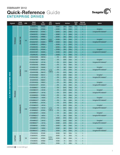
CONTINUED > 2.5-Inch HDD pg 2CONTINUED > 2.5-Inch SSD pg 3New Seagate Model Number Key, EnterpriseST 500 NM 123 1BRANDCAPACITYSEGMENTATTRIBUTESGENERATION2 letters ST = Seagate MX = Maxtor2 to 4 digits 500 = 500GB 1000 = 1000GBCapacities >9999GB:10 = 10TB 15 = 15TB2 lettersMM = Mission-Critical, 2.5-Inch, 10K MX = Mission-Critical, 2.5-Inch, 15K NM = Nearline, 3.5-Inch NX = Nearline, 2.5-Inch FM = SSD Mainstream FX = SSD Performance3 digits, non-intelligentVaries as needed, for example:Interface RPM Cache SED1 digit, intelligent 1 = 1st Generation2 = 2nd Generation3 = 3rd GenerationSeagate Partner Program MembersVisit the Sales Tools section to access the latest product roadmap, end-of-life schedule and product information. DistributorsEMEA SPP Support00-800-6890-8282US Sales Support1-800-SEAGATE or 1-405-324-4700Visit for more information or call 1-800-SEAGATE (1-800-732-4283) © 2012 Seagate Technology LLC. All rights reserved. Printed in USA. Seagate, Seagate Technology and the Wave logo are registered trademarksof Seagate Technology LLC in the United States and/or other countries. Cheetah, Constellation.2, Pulsar, Pulsar.2 and Savvio are either trademarks or registered trademarks of Seagate Technology LLC or one of its affiliated companies in the United States and/or other countries. The FIPS logo is a certification mark of NIST, which does not imply product endorsement by NIST, the U.S., or Canadian governments. All other trademarks or registered trademarks are the property of their respective owners. When referring to drive capacity, one gigabyte, or GB, equals one billion bytes and one terabyte, or TB, equals one trillion bytes. Your computer’s operating system may use a different standard of measurement and report a lower capacity. In addition, some of the listed capacity is used for formatting and other functions, and thus will not be available for data storage. Actual data rates may vary depending on operating environment and other factors. The export or re-export of hardware or software containing encryption may be regulated by the U.S. Department of Commerce, Bureau of Industry and Security (for more information, visit ). Seagate reserves the right to change, without notice, product offerings or specifications. QR501.14-1202US, February 20122 Self-Encrypting Drives (SED) and FIPS 140-2 Validated drives are not available in all models or countries. May require TCG-compliant host or controller support.3 See FIPS 140-2 Level 2 Certificate at /groups/STM/cmvp/documents/140-1/1401val2010.htm#12994 Data provided is based on format at 512 bytes.View a brief training presentation on how our model number format has changed at /seagate/ModelNumber。

联想(北京)有限公司HUS存储监控配置手册LIM系列文档V1.0致谢!感谢您使用联想基础架构监控方案。
本手册受到著作权法律法规保护,未经联想(北京)有限公司授权,任何人士不得以任何方式对此文档进复制、抄录、删减或将其编译为机读格式,以任何形式在可见存储中存储、在有线或无线网络中传输,或以任何形式翻译为任何文字。
适用范围:本文适用于如下存储:Lenovo-HDS HUS110 Lenovo-HDS HUS130 Lenovo-HDS HUS150目录适用范围: (3)术语 (5)1.概述 (6)2.通过HSNM配置HUS存储的SNMP Trap (7)术语下表列出了本文档中所使用的术语及其相应说明。
1.概述LIM Server对Lenovo-HDS HUS系列存储的监控,可以通过SNMP Trap的方式,获得存储上的报警信息。
Lenovo-HDS HUS系列存储,通过HSNM存储管理软件来管理。
以下配置需要通过HSNM进行。
2.通过HSNM配置HUS存储的SNMP Trap登录HSNM2管理软件,点击左侧“Arrays”,进入存储列表,选择要配置的HUS存储并点击,如下图(图中对第4个存储进行配置)。
进入存储后,点击左侧Settings,如果找不到SNMP Agent,则需要先将它激活,如果有该选项,则跳过激活步骤。
激活方式如下:1、点击License,在右侧列表中,勾选SNMP-AGENT,在页面下方点击Change Status。
2、然后在确认页面,在Enable后面勾选yes,点击OK,至此,激活生效。
这样Settings选项下面,会出现SNMP Agent项。
在左侧点击Settings下面的SNMP Agent,进入配置页面,点击Edit SNMP Settings进入编辑页面。
在SNMP配置编辑页面,按照下图,INITIAL sysContact 是存储设备管理人的信息,INITIAL sysLocation是开启SNMP agent 设备的位置,第3行COMMUNITY值,设为lenovo,并在第4行输入ALLOW ALL OPERATIONS,MANAGER是SNMP Trap发送的目的地址,在此输入LIM Server的地址(图中是10.99.76.190),第6行SEND ALL TRAPS TO PORT 162,指定了Trap发送使用的端口号为162,最后一行的WITH COMMUNITY “lenovo”,给Trap配置了community值。

日立全热交换机说明书
全热交换器的关键零部件是全换热芯体,房间内排除的污浊空气和户外送进的新鲜空气既使用传热板互相交换温度,另外又使用板上的微孔互相交换环境湿度,进而做到既通风内循环又维持房间内温、环境湿度平稳的实际效果。
这也是全换热流程。
当全热交换器在夏天空调制冷期运作时,新风系统从排风系统中得到冷量,使温度下降,另外被排风系统干燥,使新风系统环境湿度下降;在冬天运作时,新风系统从排风系统中得到热量,使温度上升,另外被排风系统加湿。
双向内循环:室内室外双向内循环,新风系统和污风等量置换,按照顾客标准可完成正负压实际操作;新风系统和排风系统完全分隔,完全避免互相污染产生。
过滤系统处置:配备不一样过滤器材,新风系统过滤系统处置,可有效性净化室内空气。
适用建筑法律法规标准。
配装不一样的过滤装置可有效性避免积灰和有害物质等空气污染物进到房间内。
按照洁净度等级标准可配备中、高效过滤器。
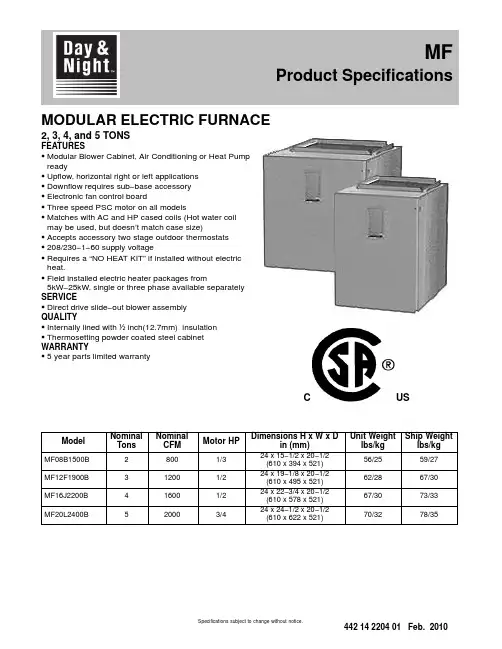
MODULAR ELECTRIC FURNACE2, 3, 4, and 5 TONSFEATURESS Modular Blower Cabinet, Air Conditioning or Heat Pump readyS Upflow, horizontal right or left applicationsS Downflow requires sub−base accessoryS Electronic fan control boardS Three speed PSC motor on all modelsS Matches with AC and HP cased coils (Hot water coil may be used, but doesn’t match case size)S Accepts accessory two stage outdoor thermostatsS208/230−1−60 supply voltageS Requires a “NO HEAT KIT” if installed without electric heat.S Field installed electric heater packages from5kW−25kW, single or three phase available separately SERVICES Direct drive slide−out blower assemblyQUALITYS Internally lined with ½inch(12.7mm) insulationS Thermosetting powder coated steel cabinet WARRANTYS5 year parts limited warrantyUSCModel NominalTons NominalCFM Motor HPDimensions H x W x Din (mm)Unit Weightlbs/kgShip Weightlbs/kgMF08B1500B28001/324 x 15−1/2 x 20−1/2(610 x 394 x 521)56/2559/27MF12F1900B312001/224 x 19−1/8 x 20−1/2(610 x 495 x 521)62/2867/30MF16J2200B416001/224 x 22−3/4 x 20−1/2(610 x 578 x 521)67/3073/33MF20L2400B520003/424 x 24−1/2 x 20−1/2(610 x 622 x 521)70/3278/35MF Product SpecificationsSpecifications subject to change without notice.UNIT SPECIFICATIONS − ELECTRIC FURNACEModel Number MF08B1500B MF12F1900B MF16J2200B MF20L2400B Application Upflow / Horizontal / Downflow *Electrical Volts−Phase−Hz.208/230-1-60Data**Minimum Circuit Ampacity 3.1 3.6 3.67.5 Time Delay Fuse (Amps)15Max Fuse or Breaker Size(Amps)15Blower Size DD10 − 7DD10 − 8DD10 − 9DD10 − 9 Data Horsepower−Speed1/3 − 31/2 − 31/2 − 33/4 − 3 Full Load Rated (Amps) 2.5 2.9 2.9 6.0 Transformer40 VAWeight Unit / Shipping Lbs (Kg)56/59 (25/27)62/67 (28/30)70/78 (32/35)70/78 (32/35) * Accessory subbase kit required for downflow application**Disregard if electric heat is added. Refer to Electric Heat table.MODEL NUMBER IDENTIFICATION GUIDEPRODUCT FAMILYM = MODULAR M F12F1900B2SERIESSALES CODES B = MODULAR BLOWER (115V)F = MODULAR ELECTRIC FURNACE (208/230V)V = MODULAR VARIABLE SPEED BLOWER (208/230V)FIELD INSTALLED HEATER NOMINAL CFM RANGE COIL WIDTH MATCH 08 = 800B15 = 15-1/2 Cabinet 12 = 1200F19 = 19-1/8 Cabinet 16 = 1600J22 = 22-3/4Cabinet 20 = 2000L24 = 24-1/2CabinetAirflow based on no coil, no filter, no electric heat (pre−accessory external static pressure). When heaters, filters, hori-zontal drain pan and/or downflow subbase are installed in an application, airflow must be re−calculated by adding the heater static, filter static, and coil static pressures (provided in the following tables) to the pre−accessory external static amount. See Coil Specification Sheet. Add.10 for Horizontal Drain Pan Kit. Add .20 for Downflow Subbase Kit.AIRFLOW IS BLOWER ONLY, NO COIL ATTACHEDMF08ESP in wcSPEED VOLTS0.20.30.40.50.60.70.8Low 230v102910201007985960915862 208v872860845825797765721Med 230v1286127012541220118011251058 208v111311051091107010421000947High 230v1500147014321380131512501168 208v1317130512861255122011701008MF12ESP in wcSPEED VOLTS0.20.30.40.50.60.70.8Low 230v973975979979973955931 208v811815816810797780749Med 230v1284129513011305130212801246 208v1084108410841090108910651030High 230v1663167016711655163115851519 208v1383138513901390138313651328MF16ESP in wcSPEED VOLTS0.20.30.40.50.60.70.8Low 230v1020101510091002991975950 208v858845830815801780749Med 230v1379138513861379136413431309 208v1156115411491144113411201098High 230v1776178217831765173816981643 208v1496149614961495149514701433MF20ESP in wcSPEED VOLTS0.20.30.40.50.60.70.8Low 230v1492149514921475145113951308 208v1246124512381225120311751125Med 230v1969195519351890181817001570 208v1641164016331615158415101406High 230v2696260024922350219220201844 208v2417235522872200209219401774FILTER STATIC PRESSURE DROPWASHABLEFILTER SIZENOMINALDISPOSABLEFILTER SIZECFMMODEL600800100012001400160018002000 MF0814 1/4 x 201/414 x 200.050.090.130.19−−−−−−−−−−−−MF1217 3/4 x 20 1/418 x 20−−−−−−−−0.090.120.170.22−−−−−−MF1621 1/4 x 20 1/420 x 20−−−−−−−−−−−−−−0.120.150.19−−−MF2024 3/4 x 20 1/424 x 20−−−−−−−−−−−−−−0.090.110.140.18HEATER STATIC TABLE HEATER KW / STATIC DROPSingle−PhaseCFM EHIA05EHIA07EHIA10EHIA15EHIA20EHIA25 6000.010.010.01-- ---- ---- --7000.010.010.01-- ---- ---- --8000.010.010.010.01-- ---- --9000.010.010.010.01-- ---- --10000.010.010.010.010.02-- --11000.010.010.010.020.02-- --12000.010.010.010.020.02-- --13000.010.020.020.020.02-- --14000.010.020.020.020.030.03 15000.010.020.020.020.030.04 16000.010.020.020.030.030.04 17000.010.020.020.030.030.04 18000.010.020.020.030.040.04 19000.010.020.020.030.040.05 20000.010.020.020.030.040.05 Three−PhaseCFM-- ---- --EHIA10EHIA15EHIA20EHIA25 600-- ---- --0.01-- ---- ---- --700-- ---- --0.01-- ---- ---- --800-- ---- --0.010.01-- ---- --900-- ---- --0.010.01-- ---- --1000-- ---- --0.010.010.02-- --1100-- ---- --0.010.020.02-- --1200-- ---- --0.010.020.02-- --1300-- ---- --0.020.020.02-- --1400-- ---- --0.020.020.030.03 1500-- ---- --0.020.020.030.04 1600-- ---- --0.020.030.030.04 1700-- ---- --0.020.030.030.04 1800-- ---- --0.020.030.040.04 1900-- ---- --0.020.030.040.05 2000-- ---- --0.020.030.040.05 -- --DO NOT OPERATE IN THIS AREA CFM / KW LIMIT EXCEEDEDUNIT SPECIFICATIONS − No Heat KitNo Heat Kit Model Table 1Supply CircuitSupplyCircuitNo.HPMax.MotorAmpsMCABranchCircuitAMPMax Over-currentProtectionDevise(Amps)Recommended Volts Phase HertzSupply Wire75°C copperGround Wire# ofWiresWireSizeMax. Ft.Length# ofWiresMinWireSizeEHIA00KN10MF08*208160Single1/3 2.5 3.115214105114 230MF12*208160Single1/2 2.9 3.615214105114 230MF16*208160Single1/2 2.9 3.615214105114 230MF20*208160Single3/4 6.07.51521490114 230* Modular blower without electric heat Conversion: 1 foot = .305 metersTECHNICAL DATA Single Phase with Circuit BreakerMaximum RecommendedMCA OvercurSupply Wire Ground Nom.Supply Heater Max FLA Min Protective75 0 C. Copper WireHeater Supply Heati Heat kW Per Circuit kW Per Heater Motor Total Circuit Device# of Wire Max.# of MinModel VoltBTUH KW Element No.Circuit AMPS.AMPS.AMPS.Ampacity(AMPS.)Wires Size Length (Ft)Wires SizeEHIA05KB1024016378 4.8 4.8Single 4.820.0626.032.53528113110 20812283 3.6 3.6Single 3.617.3623.329.130210118110EHIA07KB10240245677.2 3.6Single7.230.0636.045.0452881110 20818425 5.4 2.7Single 5.426.0632.040.0402892110EHIA10KB10240327569.6 4.8Single9.640.0646.057.56026101110 208245677.2 3.6Single7.234.6640.650.86026115110EHIA15KB102404913414.4 4.8Single14.460.0666.082.5902411318Mult. 19.640.0646.057.56026101110Mult. 2 4.820.0020.025.025******** 2083685110.8 3.6Single10.851.9657.972.4802412818Mult. 17.234.6640.650.86026115110Mult. 2 3.617.3017.321.625210109110EHIA20KB102406551319.2 4.8Single19.280.0686.0107.51102213716Mult. 19.640.0646.057.56026101110Mult. 29.640.0040.050.0502873110 2084913414.4 3.6Single14.469.2675.294.010*********Mult. 17.234.6640.650.86026115110Mult. 27.234.6034.643.3452885110EHIA25KB102408189124 4.8Single24100.06106.0132.515021/017716Mult. 19.640.0646.057.56026101110Mult. 214.460.0060.075.0802412418 2086141818 3.6Single1886.5692.5115.71252116116Mult. 17.234.6640.650.86026115110Mult. 210.851.9051.964.9702690110TECHNICAL DATA Single−Phase with Terminal BlockMaximum RecommendedMCA OvercurSupply Wire Ground Nom.Supply Heater Max FLA Min Protective75 0 C. Copper WireHeater Supply Heati Heat kW Per Circuit kW Per Heater Motor Total Circuit Device# of Wire Max.# of MinModel VoltBTUH KW Element No.Circuit AMPS.AMPS.AMPS.Ampacity(AMPS.)Wires Size Length (Ft)Wires SizeEHIA05KN1024016378 4.8 4.8Single 4.820.0626.032.53528113110 20812283 3.6 3.6Single 3.617.3623.329.130210118110EHIA07KN10240245677.2 3.6Single7.230.0636.045.0452881110 20818425 5.4 2.7Single 5.426.0632.040.0402892110EHIA10KN10240327569.6 4.8Single9.640.0646.057.56026101110 208245677.2 3.6Single7.234.6640.650.86026115110TECHNICAL DATA Three Phase with Circuit BreakerMaximum RecommendedMCA OvercurSupply Wire Ground Nom.Supply Heater Max FLA Min Protective75 0 C. Copper WireHeater Supply Heati Heat kW Per Circuit kW Per Heater Motor Total Circuit Device# of Wire Max.# of MinModel VoltBTUH KW Element No.Circuit AMPS.AMPS.AMPS.Ampacity(AMPS.)Wires Size Length (Ft)Wires SizeEHIA10HB10240327569.6 3.2Single9.623.1629.136.44038117110 208245677.2 2.4Single7.220.0626.032.53538131110EHIA15HB102404913414.4 4.8Single14.434.7640.750.9603613218 2083685110.8 3.6Single10.830.0636.045.0453894110EHIA20HB102406551319.2 3.2Single19.246.2652.265.3703416518Mult. 1 6.415.4621.426.830310102110Mult. 212.830.8030.838.54038110110 2084913414.4 2.4Single14.440.0646.057.5603611718Mult. 1 4.813.3619.324.230310113110Mult. 29.626.7026.733.33538127110EHIA25HB1024081891244Single2457.8663.879.8803413518Mult. 1819.3625.331.63538134110Mult. 21638.5038.548.2503888110 20861418183Single1850.0656.070.0703415318Mult. 1616.7622.728.33031096110Mult. 21233.3033.341.74538102110Conversion: 1 foot = .305 metersHEATER STAGING Single−PhaseELECTRIC HEATER VOLTAGETOTAL HEAT KW1st STAGE KW (W1)2nd STAGE KW (W2) 208V240V208V240V208V240VEHIA05KB10208−240/1/60 3.6 4.8 3.6 4.8−−EHIA07KB10208−240/1/60 5.47.2 5.47.2−−EHIA10KB10208−240/1/607.29.67.29.6−−EHIA15KB10208−240/1/6010.814.47.29.6 3.6 4.8 EHIA20KB10208−240/1/6014.419.27.29.67.29.6EHIA25KB10208−240/1/6018247.29.610.814.4EHIA05KN10208−240/1/60 3.6 4.8 3.6 4.8−−EHIA07KN10208−240/1/60 5.47.2 5.47.2−−EHIA10KN10208−240/1/607.29.67.29.6−−Three−PhaseELECTRIC HEATER VOLTAGE TOTAL HEAT KW1st STAGE KW (W1)2nd STAGE KW (W2)208v240v208v240v208v240v EHIA10HB10208−240/3/607.29.67.29.6−−EHIA15HB10208−240/3/6010.814.410.814.4−−EHIA20HB10208−240/3/6014.419.2 4.8 6.49.612.8 EHIA25HB10208−240/3/601824681216Conversion: 1 foot = .305 metersHEAT STRIP STAGINGSingle−Stage OperationTwo−Stage Capable Three−Stage Capable (with ODTS only)(no staging − all electric heat together)Single−Phase EHIA05KB / KNEHIA15KBEHIA20KBEHIA25KBEHIA25KB EHIA07KB / KNEHIA10KB / KNEHIA15KBEHIA20KBEHIA25KBThree−Phase EHIA10HB EHIA10HBEHIA20HBEHIA25HB EHIA15HB EHIA15HBEHIA20HB EHIA20HBEHIA25HB EHIA25HBACCESSORIESModel Description Used with MF ModelEHIA00KN10No Heat Kit08, 12, 16, 20 EHIA05KB10 5 kW 1-Phase w/C.B.08, 12, 16, 20 EHIA05KN10 5 kW 1-Phase w/T.B.08, 12, 16, 20 EHIA07KB107.5 kW 1-Phase w/C.B.08, 12, 16, 20 EHIA07KN107.5 kW 1-Phase w/T.B.08, 12, 16, 20 EHIA10KB1010 kW 1-Phase w/C.B.08, 12, 16, 20 EHIA10KN1010 kW 1-Phase w/T.B.08, 12, 16, 20 EHIA15KB1015 kW 1-Phase w/C.B.08, 12, 16, 20 EHIA20KB1020 kW 1-Phase w/C.B.12, 16, 20 EHIA25KB1025 kW 1-Phase w/C.B.16, 20 EHIA10HB1010 kW 3-Phase w/C.B.12, 16, 20 EHIA15HB1015 kW 3-Phase w/C.B.12, 16, 20 EHIA20HB1020 kW 3-Phase w/C.B.16, 20 EHIA25HB1025 kW 3-Phase w/C.B.16, 20KN = 1-phase T.B. = terminal blockKB = 1-phase C.B. = circuit breakerHB = 3-phase SINGLE POINT WIRING KITModel DescriptionUsed withHeater size AMFK20SPA Single Point Wiring Kit (4-pole)15-20 kW AMFK30SPA Single Point Wiring Kit (6-pole)25 kW OUTDOOR THERMOSTATModel DescriptionUsed withHeater size AMF002OTA2-Stage ODTS15 kW andabove DOWNFLOW KITModel DescriptionUsed withMF Model AMF008DFB1Downflow kit08 AMF012DFB1Downflow kit12 AMF016DFB1Downflow kit16 AMF020DFB1Downflow kit20International Comfort Products, LLC Lewisburg, Tennessee 37091 U.S.A.。
URL:e pc at al o g s .c ome p c a t a l o g s .c o mTo The ReaderAdditional ReferencesManual CompositionPage NumberThis manual is written for an experienced technician to provide technical information needed to maintain and repair this machine.The machine specification and description according to destination may be explained on this manual. Be sure to thoroughly read this manual for correct product information and service procedures.Please refer to the other materials (operator’s manual, parts catalog, engine technical material and Hitachi training material etc.) in addition to this manual.This manual consists the Technical Manual, the Workshop Manual and the Engine Manual.Information included in the Technical Manual:Technical information needed for redelivery and delivery, operation and activation of all devices and systems, operational performance tests, and troubleshooting procedures.Each page has a number, located on the center lower part of the page, and each number contains the following information:Example:Technical Manual: T 1-3-5T Technical Manual 1Section Number 3Group Number5Consecutive Page Number for Each GroupIf you have any questions or comments, at if you found any errors regarding the contents of this manual,please contact using “Service Manual Revision Request Form” at the end of this manual. (Note: Do not tear off the form. Copy it for usage.):Technical Information Center Hitachi Construction Machinery Co., Ltd. TEL: 81-29-832-7084 FAX: 81-29-831-1162E-mail:*****************************Information included in the Workshop Manual:Technical information needed for maintenance and repair of the machine, tools and devices needed for maintenance and repair, maintenance standards, and removal / installation and assemble / disassemble procedures.Information included in the Engine Manual:Technical information needed for redelivery and delivery and maintenance and repair of the machine, operation and activation of all devices and systems, troubleshooting and assemble / disassemble procedures.Workshop Manual: W 1-3-2-5W Workshop Manual 1Section Number 3Group Number 2Sub Group Number5Consecutive Page Number for Each Groupe pc at al o g s .c omSafety Alert Symbol and Headline NotationsIn this manual, the following safety alert symbol and signal words are used to alert the reader to the potential for personal injury of machine damage.d This is the safety alert symbol. When you see thissymbol, be alert to the potential for personal injury.Never fail to follow the safety instructions prescribed along with the safety alert symbol.The safety alert symbol is also used to draw attention to component/part weights.To avoid injury and damage, be sure to use appropriate lifting techniques and equipment when lifting heavy parts.d CAUTION:Indicates potentially hazardous situation which could, if not avoided, result in personal injury or death.IMPORTANT:Indicates a situation which, if not conformed to the instructions, could result in damage to the machine.f NOTE:Indicates supplementary technical information or know-how.Units UsedQuantity To Convert FromInto Multiply By Length mm in 0.03937mmft 0.003281VolumeLUS gal 0.2642L US qt 1.057m 3yd 3 1.308Weight kg lb 2.205Force N kgf 0.10197N lbf 0.2248TorqueN·m kgf·m 0.10197Pressure MPa kgf/cm 210.197MPa psi 145.0PowerkW PS 1.360kW HP 1.341Temperature °C °F °C×1.8+32Velocity km/h mph 0.6214min -1rpm1.0Flow rateL/min US gpm 0.2642mL/revcc/rev1.0f NOTE:The numerical value in this manual might bedifferent from the above-mentioned table.SI Units (International System of Units) are used in this manual. MKSA system units and English units are also indicated in parentheses just behind SI units.Example: 24.5 MPa (250 kgf/cm 2, 3560 psi)A table for conversion from SI units to other system units is shown below for reference purposes.e pc at al o g s .c omSYMBOL AND ABBREVIATIONSymbol / Abbreviation NameExplanationTO Technical manual (Operational principle)Technical manual (Operational Principle). TT Technical manual (Troubleshooting)Technical manual (Troubleshooting). T/M Technical manual Technical manual.W, W/M Workshop manualWorkshop manual (Removal and Installation, Disassembly and Assembly).MC Main Controller Main controller. MC controls the engine, pump, and valveaccording to the machine operating condition.ECU Engine Control Module Engine controller. ECU controls fuel injection amountaccording to the machine operating condition.GSMGlobal System for Mobile communications controller Communication controller. GSM is a type of wireless communication system, is used in more than on 100countries around Europe and Asia, and becomes the factual global standards of the mobile telephone.GPS Global Positioning System Global positioning system. CANController Area Network CAN communication. CAN is a serial communicationsprotocol internationally-standardized by ISO (International Organization for Standardization).A/C Air Conditioner Air conditioner. OP , OPT Option Optional component. MPDr. Maintenance Pro Dr.MPDr. is software that troubleshooting, monitoring, andadjustment.A/I Auto-Idle Auto-idle. WU Warming-Up Warming-up. Li Low (Slow) Idle Slow idle engine speed. ATT Attachment Attachment. Attachment is optional parts such as breaker,crusher, and pulverizer in this manual.HI, Hi High Travel fast position.LO, Lo Low Travel slow position.EGRExhaust Gas Recirculation The EGR control re-circulates a part of exhaust gas in theintake manifold and combines it with intake-air. Therefore, combustion temperature is lowered and generation of oxide of nitrogen (NOx) is controlled.CSDCold Start Device Engine start device at low temperature. It increasinglyadvances the fuel injection timing and increases the fuel injection amount a little when coolant temperature is less than 5 °C. Therefore, the engine starting is improved.e pc at al o g s .c omBuy nowHitachi Hydraulic Excavator ZX85USB-5A Workshop Manual PDF With Instant Download。
第一章安装配置本章主要描述通过管理软件对存储进行配置和设置。
1.通过浏览器直接访问AMS2000存储,则进行基本状态的检查和相关的维护;2.存储的配置需要通过Storage Navigator Management 2进行(简称SNM2,下同);3.AMS2000存储的管理是三层结构,浏览器-》服务器-》存储,SNM2是服务器软件,客户端使用浏览器方式进行。
1.1 安装管理软件AMS2000系列管理软件的安装说明:1.SNM2软件可以支持多种平台,包括Windows系列和Linux,本文以Windows为例进行说明;2.SNM2有Web和CLI两种方式,本文以Web方式说明;3.Server: Windows XP/2003/Vista/2008 with 1.5GB free disk.4.Browser: IE6.0 (SP1) or IE7.0. The 64-bit IE is not supported.5.JRE: JRE 1.6.0_10. The 64-bit JRE is not supported.6.如果Sever已经安装HiCommand其它软件,安装之前需要停了这些软件的Services。
7.建议SNM2安装在没有使用AMS2000磁盘的服务器。
8.建议安装SNM2的Windows不要使用休眠等电源管理功能。
9.可以实施Update安装,相同版本的Update安装视作Uninstall。
10.安装时,需要输入SNM2的IP,不要输入127.0.0.1或localhost1.1.1 安装过程安装过程按照画面提示进行输入相关信息;注意一定要输入你的笔记本(或者服务器)的固定IP地址,该IP地址必须能与存储进行互通的(同一个网段是好主意)1.1.2 SNM2服务器端服务的操作•建议不要使用Windows的图形界面启动或停止SNM2的Services•c:\Program Files\HiCommand\Base\bin\hcmdssrv.exe /startKAPM06440-I The HiRDB service has already StartedKAPM05007-I Already started service. Service-name HBase Storage Mgmt Web serviceKAPM05007-I Already started service. service-name =HBase Storage MgmtCommon service.•c:\Program Files\HiCommand\Base\bin\hcmdssrv.exe /stopKAPM05017-I Succeeded in stopping of service. Service -name =HBase storage mgmt common service.KAPM05017-I Succeeded in stopping of service. Service -name=HBase storage mgmt web service.KAPM06441-I The HiRDB services has already stopped1.1.3 客户端Java需求:•JRE 1.6.0_10 or newer不需要设置•less than 1.6.0_10–Start◊Settings◊Control Panel.–From the Control Panel, select the Java.–Click View of the upper position in the Java tab.–Enter “-Xmx192m”–(“-Xmx216m” when the Hitachi Storage Navigator Modular 2 is version 7.00 or later)1.2 启动界面http://<IP address>:23015/StorageNavigatorModular/登陆用户名/密码:1.3 注册存储SNM2软件初次使用时尚无存储进行管理,软件会自动提示注册存储;如果SNM2原来已经有存储在使用,则点击Add Array,弹出以下画面,执行四个流程:Introduction Screen > Search Array Screen > Add Array Screen> Finish ScreenIntroduction Screen解释SNM2注册存储的说明。