DYNAFORM 5.9 发布说明(中文版)
- 格式:doc
- 大小:54.50 KB
- 文档页数:8

DYNAFORM 5.9.3发布说明(2016年3月28)主要功能改进1. 在板料成形中新增了自动迭代回弹补偿功能。
2. 在板料成形中新增了一个支持变厚板(Tailor Rolled Blank)的功能。
3. 在板料成形的成形工序中新增了一个切缝(Lancing)功能。
4. 新增了裁剪实体单元的功能。
5. 在自动设置(AutoSetup) 中添加了工艺模板,可用于板料成形的特殊实例。
6. 板料/修边线优化(Blank/Trim Line Development)功能中的改进包括:a) 将板料优化(Blank Development)和切边线优化(Trim Line Development)功能合并为板料/修边线优化(Blank/Trim Line Development)。
b) 新增了同时优化板料轮廓线和修边线的功能。
c) 新增了优化部分板料轮廓线和部分修边线的功能。
d) 新增了使用修边的方式优化板料轮廓线的功能。
7. 新增了分段创建和编辑等效拉延筋的功能。
8. 在热成形中新增了板料冷却和修边功能。
9. 新增了复合材料的仿真功能(热塑性预浸渍过程)。
10. 新增了成形和翻边的隐式分析功能。
11. 在管材弯曲模拟中新增了非圆管功能。
12. 在管材弯曲模拟中新增了一个用于弯管的回弹检查,并添加了一个补偿过程。
13. 一步法求解器“MSTEP”中新改进的功能:a) 改进了实例的结果,其中一些展开的直线是弯曲的而非直的。
b) 改进了深度拉延零件层的轮廓线。
c) 修复了在网格平均法向的冲压方向调整过程中造成轮廓线自相交的问题。
d) 修复了造成展开的轮廓线远远短于比实际轮廓线的问题。
BSE 模块中新实现的性能模块中新实现的性能,,特征特征和功能和功能1. 将GUI 名称从MSTEP 更改为生成轮廓线(Generate Outline)。
2. 简化了MSTEP 约束定义的图形用户界面。
3. 新增了允许用户通过选择边界节点来添加约束的功能。

ConfigED Lite产品手册和ConfigLite 5.x一起使用○c欧陆传动有限公司 2002版权所有权力均受到严格保护。
未有获得欧陆传动有限公司的书面同意,不允许将本文件的任何一部分存储在检索系统中或者以任何形式传播给出去。
为了保证本文件的准确性,尽管做了很大的努力,但仍然有可能在没有事先通知的情况下对文件进行修改和补充,由此导致的损坏、伤害或费用,欧陆传动有限公司不承担责任。
本手册中详细的工序只能由受过充分培训或有经验的人员来操作。
设备的安装、操作和维修应当由合格的人员进行。
一个合格人员是指在技术上是有能力的,熟悉所有的安全信息并且具有安全方面的经验,熟悉设备的操作,了解高电压电气系统危险性。
如果不遵守这些指导可能造成设备损坏或人员伤亡。
如果你不能确保你有资格或你不理解本手册中的一些工续,请联系欧陆传动有限公司的服务部门来请求帮助。
请确认本手册中的手续,包括安装,请确认产品型号和本手册中的一致。
如果发现任何矛盾,请立即联系客户服务中心。
美国印制 RG352747 第六期ConfigED Lite 手册目录第一章 绪论什么是ConfigEDLite ?..................................................................................................................................1 - 1 离线配置..............................................................................................................................................................1 - 1 计算机兼容性.................................................................................................................................................... 1 - 2 第二章 操作 拆包指令..............................................................................................................................................................2 - 1 特殊处理..............................................................................................................................................................2 - 1 第三章 安装与设置安装步骤..............................................................................................................................................................3 - 1 与驱动器通讯....................................................................................................................................................3 - 4 第四章 创建配置打开一个默认配置...........................................................................................................................................4 - 1 显示此配置.........................................................................................................................................................4 - 2 配置参数..............................................................................................................................................................4 - 3 显示参数..............................................................................................................................................................4 - 3 改变参数..............................................................................................................................................................4 - 4 实现连接..............................................................................................................................................................4 - 4 排列功能块.........................................................................................................................................................4 - 5 保存配置..............................................................................................................................................................4 - 6 打开当前配置......................................................................................................................................................4 -7 安装配置...............................................................................................................................................................4 -7 使用“Get lnfo” ....................................................................................................................................................4 -7 安装配置...............................................................................................................................................................4 -8 更新配置...............................................................................................................................................................4 -8 建立配置模块......................................................................................................................................................4 -9 打印配置...............................................................................................................................................................4 -9 第五章 文件配置文件配置...............................................................................................................................................................5 -1 检查文件...............................................................................................................................................................5 -1 打印文件列表.....................................................................................................................................................5 –2 _______________________________________________________________________________ ConfigED Lite 手册 目录-1ConfigED Lite 手册第六章 高级特征模型........................................................................................................................................................................6 -1 建立模型...............................................................................................................................................................6 -1 自动数据录入......................................................................................................................................................6 -3 第七章 故障诊断通信问题...............................................................................................................................................................7 -1 不匹配的波特率.................................................................................................................................................7 -1 波特率设置过高.................................................................................................................................................7 -1 错误的通信端口.................................................................................................................................................7 -1 驱动器P3模式设置错误..................................................................................................................................7 -1 错误信息...............................................................................................................................................................7 -2 第八章 参考功能模块...............................................................................................................................................................8 -1 内部表格链接......................................................................................................................................................8 -1 组合的链接..........................................................................................................................................................8 -2 制图........................................................................................................................................................................8 -3 制图工具...............................................................................................................................................................8 -4 显示选项...............................................................................................................................................................8 -6 详解制图...............................................................................................................................................................8 -6 便条.................................................................................................................................................8 -6 第九章 附录菜单........................................................................................................................................................................9 -1 文件........................................................................................................................................................................9 -1 编辑........................................................................................................................................................................9 -1 命令........................................................................................................................................................................9 -1 窗口........................................................................................................................................................................9 -2 字体........................................................................................................................................................................9 -2 格式........................................................................................................................................................................9 -2 帮助........................................................................................................................................................................9 –2 _______________________________________________________________________________目录-2 ConfigED Lite 手册第一章绪论第一章绪论什么是ConfigED Lite?ConfigED Lite(CE Lite)是一种用来配置欧陆控制器的软件工具。

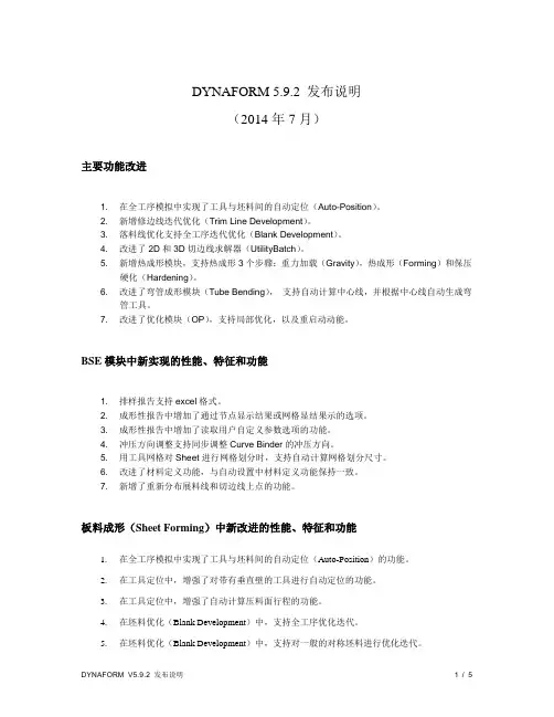
DYNAFORM 5.9.2 发布说明(2014年7月)主要功能改进1. 在全工序模拟中实现了工具与坯料间的自动定位(Auto-Position)。
2. 新增修边线迭代优化(Trim Line Development)。
3. 落料线优化支持全工序迭代优化(Blank Development)。
4. 改进了2D和3D切边线求解器(UtilityBatch)。
5. 新增热成形模块,支持热成形3个步骤:重力加载(Gravity),热成形(Forming)和保压硬化(Hardening)。
6. 改进了弯管成形模块(Tube Bending),支持自动计算中心线,并根据中心线自动生成弯管工具。
7. 改进了优化模块(OP),支持局部优化,以及重启动动能。
BSE模块中新实现的性能、特征和功能1. 排样报告支持excel格式。
2. 成形性报告中增加了通过节点显示结果或网格显结果示的选项。
3. 成形性报告中增加了读取用户自定义参数选项的功能。
4. 冲压方向调整支持同步调整Curve Binder的冲压方向。
5. 用工具网格对Sheet进行网格划分时,支持自动计算网格划分尺寸。
6. 改进了材料定义功能,与自动设置中材料定义功能保持一致。
7. 新增了重新分布展料线和切边线上点的功能。
板料成形(Sheet Forming)中新改进的性能、特征和功能1.在全工序模拟中实现了工具与坯料间的自动定位(Auto-Position)的功能。
2.在工具定位中,增强了对带有垂直壁的工具进行自动定位的功能。
3.在工具定位中,增强了自动计算压料面行程的功能。
4.在坯料优化(Blank Development)中,支持全工序优化迭代。
5.在坯料优化(Blank Development)中,支持对一般的对称坯料进行优化迭代。
6.在坯料优化(Blank Development)中,支持对不在X-Y平面内的坯料轮廓线进行优化迭代。
7.增加了切边线优化迭代模块。
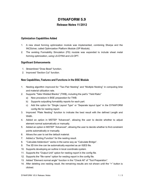
DYNAFORM 5.9Release Notes 11/2012Optimization Capabilities Added1. A new sheet forming optimization module was implemented, combining Sherpa and theINCSolver, called Optimization Platform Module (OP Module).2. The existing Formability Simulation (FS) module was expanded to include sheet metalforming optimization, using LS-DYNA and LS-OPT.Significant Enhancements1. Streamlined “Draw Bead” function.2. Improved “Section Cut” function.New Capabilities, Features and Functions in the BSE Module1. Nesting algorithm improved for “Two Pair Nesting” and “Multiple Nesting” in computing timeand material utilization rate.2. Supports “Tailor Welded Blanks” (TWB), including the part’s "Yield Ratio"a) New procedure in BSE preparation for TWB.b) Supports outputting formability reports for each part.c) Add the option for "Single Layout Type" or "Separate layout type" in the DYNAFORMconfig file for nesting report.3. Improved “Plate Nesting” function to indicate the best result with the defined Length andWidth.4. Added an option in MSTEP "Advanced", allowing the user to decide whether to adjustelement normal automatically or manually.5. Added an option in MSTEP "Advanced", allowing the user to decide whether to find constraintpoints automatically or manually.6. Allows the user to set the default material.7. Added a “Sorting Function” for the nesting result.8. "Calculate Addendum" works in the same way as "Calculate Bridge".9. The 3D trim line can be automatically exported as an IGES file.10. Supports developing an outline in local coordinate system.11. Supports the "Output Unit" option for nesting report in the config file.12. Supports the "file name" option for nesting report in the config file.13. Added "Element normal angle” function in the "Check All" of "Tool Preparation".14. After deleting one nesting result, the remaining results are not shown until the “+” button isclicked.15. New option added to define decimal dimension and utilization separately.16. Added an option to adjust the width of “3D Trim Line”.17. Added an option to tip 3D Trim Line in original position or tipped position.18. Added an "Export Press dir." button to export the press direction in original position..19. Added ability to output the formability report as an .xls file.20. Batch BSE module restored.21. Batch MSTEP module restored.Newly Implemented Capabilities, Features and Functions in DFE Module1. Added a "Curve Editor" function to replace current Edit Fline in the Edit Addendum.2. Added Redo/Undo option in the Addendum Window.3. Restored DFE Simulation capability with INCSolver.Newly Enhanced Capabilities, Features and Functions Supporting AutoSetup in the Formability Module1. Redesigned the draw bead GUI.a) Added draw bead shape template to convert line bead force to bead shape.b) Ability to define variable bead.c) Ability to use “Curve Editor” to create and edit line bead.d) Ability to create and edit “Symmetry Line Bead”.e) Ability to support “Variable Geometry Bead”.f) Ability to create the geometry bead without the thickness offset of Contact Offset.2. Developed an iterative approach for developing a Blank that will match the targeted Trim Line.3. Added an option in “Animate” to show only tools in the current stage.4. Adopted a more accurate approach to evaluate material formability, called “Formability Index”.5. If tools have been modified in “Preparation” the program automatically positions tools whenexiting “Preparation”.6. Ability to automatically positions tools, when the blank has been modified in “BlankGenerator" or the tool has been modified in "Tool Preparation".7. In the “Tool Preparation”, added a toggle on/off option to display/hide a tool.8. Changed the name of contact option from “Single Surface” to "Blank Self-contact” in “Blank”.9. Improved the function to define U, V and W-axis in defining the working coordinate system.10. Added an option in the config file, allowing the user to define the alternative name for eachstandard tool (die, punch and binder).11. Changes in the FLC curve:a) Recorded the data format (True strain or Engineering strain).b) Set "Strain Type" as global option in FLC in operation page.12. Changed the tool control of binder from force to velocity.13. Supports a new trimming card in 2D/3D trimming.14. Supports the definition of the adaptive box for mesh refinement.15. Allows the user to define 2 parallel symmetry planes for the blank.16. Added a "Save As" submenu in AutoSetup.17. Changed the default material type to 24 for the solid blank.18. Toggles off "Refining Meshes" for solid blank mesh automatically.19. Added optimization function with LS-OPT to optimize line bead, friction, binder force andblank outline.20. Changes in Stretch Forming:a) Removed both U and W-axis translation options in “Blank Positioning” dialog box.b) Changed the blank mesh normal in +Z direction to ensure that top and bottom strainresults are correct.c) Changed the bullnose mesh normal towards the blank to improve simulation results.d) Default machine kinematics only include table stroke for "Transverse Bullnose StretchForming" relaxation process, without tension cylinder motions.e) Implemented a function for “Bulldozer Stroke”.f) When a master tool velocity is chosen, DYNAFORM calculates and displays the slavevelocity values for the user.New features for Blank Generator1. Support to create Thick Shell Elements and Solid Elements.2. Added a button “Copy from BSE” linking “Blank Generator” to “BSE Outline List”.3. Added the ability to select outer line and inner holes at the same time, and assign them at thesame time.4. Add new Mesh method "Disk Mesh" to mesh Circle or Ellipse outline. The generatedelements will be distributed uniformly along the radial direction.Additional Features and Functions for Job Submitter1. Changed the message file extension from *.js to *.jsb.2. Supports ability to specify the LS-DYNA solver license.3. Added an option to open the result file (*.d3plot, *.dynain and *.fas) with eta/POST.4. Adding ability to submit jobs to the LS-DYNA/MPP solver.Enhanced and Improved Pre-Processing Capabilities1. New “Section Cut” function.a) Added ability to move section by mouse on screen.b) User can define “Cut Plane” with two cursor locations on the screen.c) Enabled 2d and 3D section functionality in Pre & Post-Processing for user-definedplanes. Enabled parallel sections and normal sections along a defined curve. Keeps theoriginal part color in the section.d) Added capability to define section plane by coordinate system or three points.e) Added capability to cut multi-section when moving the section plane on the curve.f) Added capability to measure distance and angle in 2D window.g) Added capability to save the “Cut Line” in list.h) Added ability to multi-cut for “Curve Path”.2. Set the exponent M=8 for Aluminum & Stainless materials of *MAT_036 type.3. Added capability to set a default material in the config file.4. Support new parameters "SC1" and "SC2" of *MAT_125.5. Added capability to generate the license log file, before installing DYNAFORM.6. Implemented an Optimization Platform (OP) Module, combining SHERPA and INCSolver forline bead, binder force, and blank outline.7. Added capability to view the sheet forming optimization results.8. Added the "Edit Parts" function in “Tool Preparation”.9. Added capability to highlight a selected part in the “Part” menu and added the ability to onlyshow those that are currently displayed in the list.10. Added "Outer and Inner Lines" option in "Boundary Line" to create internal and externalboundaries within the selected surfaces group.11. Added capability to display “Element Normal” with an arrow when offset from the mating tool.12. Added ability to show the part ID in the message window.13. Reduced the number of clicks when selecting elements with "By Part".14. Allows the user to fillet new tool in "Fillet Mesh".15. Added ability to select multiple parts when selecting Surface by Part.16. Redesigned the "Best Fit" GUI. Improved Auto Fit method and add new fit method "3 Points".17. Added the file extension associations with DYNAFORM product when installing. *.df isassociated with DYNAFORM, *.d3plot and *.idx are associated with eta/POST, and *.e3d is associated with e3dplayer.18. Enhanced surface mapping function to improve the generated surface quality.Newly Implemented Capabilities, Features and Function of Post-processing (eta/Post)1. Added "Mean Curvature", "Gauss Curvature", "Max Principal Curvature" and "Min PrincipleCurvature" in Curvature function.2. Added the "3 Point Gauge Check" function, which is a face defect check tool similar to“Stoning” function.3. Added the "Setting" function in "File" menu, which is the GUI of etapost.config.4. Added ability to support STL files.5. Added "Exclude", "All in Region" and "Spread" options.6. Added the "Select by Line" option, enabling the user to select a line to define an area.7. Added the "Define by Cursor Location" option in “Define Cut Plane”.8. Added "Define Path by Curve" in “Section Translation”, which enables the user to select acurve to define translation path.9. Added “Frame List” control in “Section Cut” animation.10. “Export Section” feature is linked to the section animation record. The exported are sectionsin animation frames.11. Removed "Export Cut Section" from “Section Cut” dialog. Removed “Cut Plane” items from“Section Cut” options.12. Added the "Enable Default Parameter" option in etapost.config file and linked it with the FLDfunction.13. If the value of “Enable Default Parameter” is off and there is no FLD curve in the index file, theFLD function cannot be opened.14. Improved the "Draw Bead Force Factor" function to display variable factors.15. Added the ability to support the keyword "*DRAWBEAD_VARIABLE_DF" in the index file.16. Added the ability to support the keyword "*DRAW_DIRECTION" in the index file.17. Updated “Stoning” algorithm for non-continual areas.18. Updated "Blank Outline" algorithm for more accurate results.19. Added the “List Area Maker” feature in “List Value” option.Supported Version of LS-DYNA1. Added the ability to support LS-DYNA971R6.1.0.2. There are two types of card formats in DF5.9: LS-DYNA971 R3.2 and R5+. This enables theuser to set the version of the default solver in DF 5.9. The default card format is R5+. To change the solver version, the user selects“Option”/”Edit Default Config”and “Setup”/”General” to select the preferred card output format.Newly Implemented License Server Manager1. Combined DYNAFORM license server manager, LS-DYNA license server manager andSHERPA license server manager in one GUI.2. Added the ability to support both client and server models. Under the “Client Models”, the usercan specify the network license. Under the “Server Model”, the user can install, uninstall, start and stop the license server.3. Added the ability to generate the eta.log file within the License Manager dialog.4. Implemented Sherpa licensing capability, producing and including a HOSTID number in theeta.log file.5. Added capability to import a license and combine licenses.DSA module is removed from the normal release package. It can be found in the release package “Dynaform+DSA”.。
eta/DYNAFORM5.8.1发布说明(2011年11月)主要功能改进1. 流线型的BSE界面。
2. 在DFE模块,用户现可参数化创建一个对称件的模面。
3. 增加了新产品的替换功能。
用户可轻易保留当前模面设计并访问新的产品设计曲面。
4. 新增了支持用户自定义的真实拉延筋(GEOMETRY BEAD)和等效拉延筋转换库(LineBead Conversion Library)。
5. 在自动设置模块,增加了标准氮气弹簧力曲线数据用于压边圈控制。
BSE模块中新实现的性能,特征和功能1. 新增BSE工程管理界面,允许用户在分析计算之前设置单位制、材料密度以及分析的工件类型。
2. 在预处理中,支持导入CAD数据时,同步对其进行网格划分。
3. 在预处理中的产生中间曲面(Generate Middle Surface),操作结束后,自动将中间曲面所在的层,添加到当前工具中,并移除当前工具中的其它层。
4. 在预处理中的分离曲面(Separate Surface),操作结束后,允许用户选择顶部曲面或底部曲面所在的层,添加到当前工具中,并移除当前工具中的其它层。
5. MSTEP网格(MSTEP Mesh)类型现为预处理中的曲面网格划分(Surface Mesh)中的默认工件网格划分。
6. 在定义对称(Symmetry)时,程序自动检查零件是否关于对称平面对称。
7. 在冲压方向调整(Tipping)中加入新的自动调整冲压方向的方法:网格法向。
将所选网格的平均法向作为冲压方向。
8. 增强了一模两件(Double Attached)、孔填充(Inner Fill)、边界光顺(BoundarySmooth)、端头补充(Sidestep)功能,具体可以参考DFE模块。
9. 把一步法求解(MSTEP)、坯料轮廓线(Outline)、坯料排样(Nesting)功能集成在一个对话框,允许用户随意切换功能。
10. 把一步法求解中的拉延(Draw)和修边线(Trim Line)进行了分离,允许用户分别进行操作,使各自功能更明确和清晰。
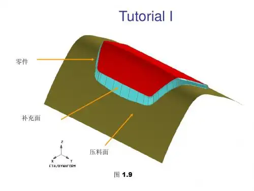
第 1 节. 背景Engineering Technology Associates Inc. (ETA)板料冲压工艺组为板金成形数值分析中的基本训练准备了这个文件。
它为新的用户提供基本的信息和训练来学习该如何使用 DYNAFORM-PC。
这是一个以 LS- DYNA 为基础的板料冲压成形数值分析技术;因此,为使用户方便和易读,这将会是“DYNAFORM-PC”的参考手册。
板料冲压成形数值分析技术在过去二十年以来有长足的发展。
这要归功于计算机的高速发展。
板料冲压成形工业仍然解决一系列的问题,包括在尝试中的试验和失败的费用。
订造一个典型的汽车面板金属模的时间要二年,其中九到十二个月为试验。
今天这个高度竞争的市场要求金属成形工业从概念上的设计到生产的产品发展周期要改进。
强烈要求成本降低,缩短生产周期,高的质量,这就需要发展Computer Aided Engineering(CAE)模拟。
CAE 应用为金属模设计和板金属形成过程模拟提供一个工具协助金属模设计者和冲压工程师在设计阶段就能评估制造的可行性; 探究替代方案设计并评估trade-offs,最后, 得出一个设计最优方案。
有限元分析 (FEA) 是分析复杂的三维板金形成的一个强力的模拟工具,可以模拟潜在的成形缺陷如开裂,起皱和回弹等问题。
它能用在金属模设计期间或如故障修理期间。
板金的可成形性可以认为是一个系统的过程,包含材料的属性,金属模设计,成形过程的控制。
DYNAFORM-PC解决包是研究上述问题和协助金属模设计者和冲压工程师完成"快速的设计原型"。
第 2 节. 板金成形应用这节提供板金成形过程和应用的基本知识和数据。
大部份数据和草图摘录在"Computer Modeling of Sheet Metal Forming Process; Theory, Verification and Application",作者为N.M. Wang和S.C. Tang。
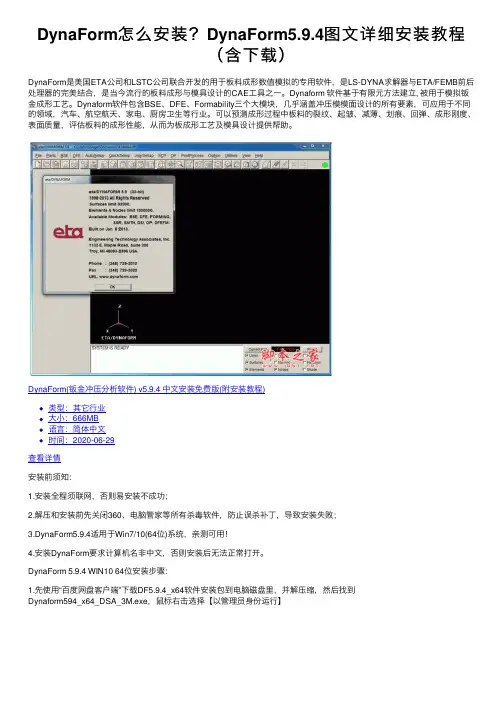
DynaForm怎么安装?DynaForm5.9.4图⽂详细安装教程(含下载)DynaForm是美国ETA公司和LSTC公司联合开发的⽤于板料成形数值模拟的专⽤软件,是LS-DYNA求解器与ETA/FEMB前后处理器的完美结合,是当今流⾏的板料成形与模具设计的CAE⼯具之⼀。
Dynaform 软件基于有限元⽅法建⽴, 被⽤于模拟钣⾦成形⼯艺。
Dynaform软件包含BSE、DFE、Formability三个⼤模块,⼏乎涵盖冲压模模⾯设计的所有要素,可应⽤于不同的领域,汽车、航空航天、家电、厨房卫⽣等⾏业。
可以预测成形过程中板料的裂纹、起皱、减薄、划痕、回弹、成形刚度、表⾯质量,评估板料的成形性能,从⽽为板成形⼯艺及模具设计提供帮助。
DynaForm(钣⾦冲压分析软件) v5.9.4 中⽂安装免费版(附安装教程)类型:其它⾏业⼤⼩:666MB语⾔:简体中⽂时间:2020-06-29查看详情安装前须知:1.安装全程须联⽹,否则易安装不成功;2.解压和安装前先关闭360、电脑管家等所有杀毒软件,防⽌误杀补丁,导致安装失败;3.DynaForm5.9.4适⽤于Win7/10(64位)系统,亲测可⽤!4.安装DynaForm要求计算机名⾮中⽂,否则安装后⽆法正常打开。
DynaForm 5.9.4 WIN10 64位安装步骤:1.先使⽤“百度⽹盘客户端”下载DF5.9.4_x64软件安装包到电脑磁盘⾥,并解压缩,然后找到Dynaform594_x64_DSA_3M.exe,⿏标右击选择【以管理员⾝份运⾏】2.点击【Next】3.许可协议,先勾选“I accept the agreement”,然后点击【Next】4.点击【Next】5.选择软件安装路径,默认安装在C盘,点击【Browse】可修改软件安装路径,注意:安装路径⽂件夹名称不能含有中⽂字符!⼩编这⾥将软件安装在D盘DynaForm5.9.4⽂件夹下,然后点击【Next】温馨提⽰:请记住软件安装⽬录,后续操作需要⽤到。
DYNAFORM 5.9.2.1 更新说明(2014年12月)2014年12月17日1. 版本号从"5.9.2" 更新到"5.9.2.1"。
2. 从"DFE 移除了工艺补充(Addendum)和逆向工程(Re-engineering)功能,并重新命名为"D-Eval"。
3. 从边界填充(Boundary Fill)中移除了边界光顺(Boundary Smooth)功能。
4. 修复了工具网格划分(Tool Mesh)中“In Original Part” 选项状态存入数据库的问题。
、5. 修复了打开两个文件时,板料成形(Sheet Forming)中板料位置错误的问题。
6. 改进了工具预处理(Tool Preparation) 中的“Replace Current…” 功能,允许替换所有工步中的工具。
7. 修复了卷边模拟(Roller Hemming) 中滚子轨迹曲线的点数超过200点的问题。
8. 修复了传统设置(UserSetup)中改变单位系统后,程序导出材料错误值的问题。
9. 修复了IGS translator中在某些情况下导入时导致程序崩溃的问题。
10. 在热成形(Hot Forming)中添加了选项,允许用户自定义时间步长DT0。
11. 修复了热成形(Hot Forming)中导入输入卡片文件时导致程序崩溃的问题。
12. 修复了板料成形(Sheet Forming) 的"Tool Position" 中程序重设工具行程由用户手动定义的问题。
13. 修复了板料成形(Sheet Forming)中"Trimming" 功能无效的问题。
14. 修复了板坯生成器(Blank Generator)中参数不同于控制参数的问题。
15. 修复了板坯生成器(Blank Generator)中某些情况下程序创建翘曲单元的问题。
DYNAFORM 5.9 发布说明(2012年12月)添加的优化性能1.实现了一个新的板料成形优化模块,将SHERPA 和INCSolver相结合,称为优化平台模块(OP Module)。
2.将现有的成形性模拟(FS)模块扩展为包括使用LS-DYNA 和 LS-OPT的板料成形优化。
新实现的许可证服务器管理器1.在许可证管理器对话框内为DYNAFORM 5.9中所有模块生成许可证申请文件eta.log。
2.新的许可证/安装管理器允许用户导航选项卡,生成DYNAFORM、LS-DYNA和SHERPA 申请许可证(INCSolver许可证包含在DYNAFORM 许可证内)所要求的信息。
第四个选项卡允许用户申请许可证并将所要求的信息一步发送。
3.将DYNAFORM、LS-DYNA和SHERPA的许可证服务器管理器组合成一个图形用户界面。
4.添加了支持客户端模式和服务器端模式的功能。
在客户端模式(Client Mode)下,用户可指定网络许可证。
在服务器端模式(Server Mode)下,用户可以安装、卸载、启动和停止许可证服务器。
5.实现了SHERPA的许可,在eta.log文件中产生并包括一个HOSTID 号。
6.添加了导入和合并许可证的功能。
7.添加了在许可证管理器对话框内生成eta.log文件的功能。
主要功能改进1.优化性能,主要是拉延分析中的拉延比率。
2.基于产品修边线的自动迭代板料开发。
3.流线型的拉延筋(Draw Bead)功能。
4.改进的截面线(Section Cut)功能。
BSE模块中新实现的性能,特征和功能1.从计算时间和材料利用率方面,改进了对排(Two-Pair Nesting)和混排(Multiple Nesting)的排样算法。
2.支持拼焊板(TWB),包括零件的重量比(Yield Ratio):a)在BSE预处理中为拼焊板的定义设置了新的流程。
b)支持为每个零件输出成形性报告。
c)在DYNAFORM 配置文件中为排样报告添加了“Single Layout Type”或“Separate Layout Type”选项。
3.改进的平板排样(Plate Nesting)功能通过定义的长度和宽度获得最好的排样结果。
4.在快速求解的高级(Advanced)选项中添加了一个选项,允许用户确定是否自动或手动调整单元法向。
5.在快速求解的高级(Advanced)选项中添加了一个选项,允许用户确定是否自动或手动找出约束点。
6.允许用户设置默认的材料。
7.为排样结果添加了排序(Sorting)功能。
8.计算补充余量(Calculate Addendum)和计算搭边(Calculate Bridge)的计算方式相同。
9.3D修边线可自动导出为IGES格式文件。
10.支持在局部坐标系上创建轮廓线。
11.支持配置文件中排样报告的输出单位(Output Unit)选项。
12.支持配置文件中排样报告的文件名称(File Name)选项。
13.在工具预处理(Tool Preparation)的检查所有(Check All)菜单下增加了单元法向夹角(Element Normal Angle)功能。
14.在删除一个排样结果后,直到单击“+”按钮才显示其余结果。
15.新增了选项用来分别定义十进制尺寸和排样利用率(Utilization)。
16.添加了一个选项,用来调整3D修边线的宽度。
17.在原始位置或调整冲压方向位置添加了一个选项用来调整3D修边线的冲压方向。
18.添加了导出冲压方向(Export Press dir.)按钮,在原始位置导出冲压方向。
19.新增了将成形性报告输出为*.xls文件的功能。
20.恢复了批量排样(Batch BSE)模块。
21.恢复了批量快速求解(Batch MSTEP)模块。
DFE模块中新实现的性能,特征和功能1.添加了曲线编辑器(Curve Editor)功能替换编辑工艺补充面(Edit Addendum)中的编辑Fline(Edit Fline)功能。
2.在工艺补充面窗口(Addendum Window)添加了重做(Redo)和撤消(Undo)功能。
3.恢复了基于INCSolver的DFE模拟功能。
新改进的性能、特征和功能,用于支持成形性模块中的自动设置(AutoSetup)1.重新设计了拉延筋图形用户界面:a)添加了拉延筋形状模板库,将等效拉延筋阻力转换为拉延筋对应的形状。
b)支持变拉延筋的定义。
c)使用曲线编辑器(Curve Editor)功能创建和编辑等效拉延筋。
d)创建和编辑对称等效拉延筋(Symmetry Line Bead)。
e)支持变截面几何拉延筋(Variable Geometry Bead)。
f)创建几何拉延筋时,有接触偏置(Contact Offset)不考虑板料的厚度。
2.增加了一种迭代方法用于开发匹配目标修边线的板料。
3.在动画(Animate)中添加了一个选项,仅显示当前工步工具。
4.采用了更精确的方法评估材料成形性,称为成形性指标(Formability Index)。
5.如果在工具预处理(Tool Preparation)中修改了工具,当退出预处理时,程序将自动定位工具。
6.如果在坯料生成器(Blank Generator)中修改了板料,或在工具预处理(Tool Preparation)中修改了工具,程序将自动定位工具。
7.在工具预处理(Tool Preparation)中,添加了打开/关闭选项来显示/隐藏一个工具。
8.在板料(Blank)页面中,将接触选项的名称从单面接触(Single Surface)更改为板料自接触(Blank self-contact)。
9.定义工作坐标系时,改进了定义U、V和W轴的功能。
10.在配置文件中增加了一个选项,允许用户为每个标准工具(凹模、凸模和压边圈)定义可选的名称。
11.FLC 曲线中的功能更新:a)记录了数据类型(真实应变或工程应变)。
b)将操作(Operation)页面中FLC的应变类型(Strain Type)设置为全局选项。
12.将压边圈(Binder)的工具控制从力(Force)更改为速度(Velocity)。
13.支持2D/ 3D修边中新的卡片。
14.支持为网格细化自适应盒的定义。
15.允许用户为板料定义两个平行的对称平面。
16.在自动设置(AutoSetup)中添加了另存为(Save As)子菜单。
17.将实体板料的默认材料类型更改为24号材料。
18.自动为实体板料网格关闭网格细化分(Refining meshes)选项。
19.添加了使用LS-OPT优化等效拉延筋、摩擦力、压边力和板料轮廓线的功能。
20.蒙皮拉形(Stretch Forming)中的功能更新:a)移除了板料定位对话框中的U轴和W轴平移选项。
b)更改了板料网格法向,以确保顶部和底部应变结果的正确性。
c)使钳口(Bullnose)的网格法向指向板料,以改进模拟结果。
d)对于横向蒙皮拉形Bullnose的Relaxation工序而言,默认的机器运动仅包括工作台行程(Table Stroke),不包括拉伸缸位移(Tension Cylinder Motion)。
e)实现了Bulldozer行程(Bulldozer Stroke)的新功能。
f)当选择了一个主工具的速度时,DYNAFORM 自动计算并显示从工具的速度。
坯料生成器(Blank Generator)的新特征1.支持创建厚壳单元(Thick Shell Elements)和实体单元(Solid Elements)。
2.添加了从BSE复制(Copy from BSE)按钮,将坯料生成器(Blank Generator)与BSE轮廓线列表(BSE Outline List)相连接起来。
3.添加了同时选择并生成轮廓线和孔的功能。
4.添加了新的网格划分方式“Disk Mesh”对圆形和椭圆形轮廓线进行网格划分,生成的单元将沿半径方向均匀分布。
任务提交器(Job Submitter)的特征和功能1.将消息文件扩展名从*.js更改为*.jsb。
2.支持指定LS-DYNA 求解器许可证。
3.增加了一个按钮,允许通过eta/POST 打开结果文件(*.d3plot, *.dynain和*.fas)。
4.支持提交任务到LS-DYNA/MPP 求解器。
改进和增强的前处理性能1.新增的截面功能a)增加了通过鼠标在屏幕上移动截面的功能。
b)用户现可通过两点在屏幕上定义裁切平面(Cut Plane)。
c)允许为用户自定义的平面启用前处理和后处理的2D和3D截面功能,允许平行截面并创建了这些截面的曲面,保持了截面的原始零件层颜色。
d)添加了通过坐标系或三点定义截面的功能。
e)在曲线上移动截面时,添加了截取多个截面的功能。
f)添加了在2D窗口测量距离和角度的功能。
g)添加了在列表中保存截面线(Cut Line)的功能。
h)添加了曲线路径(Curve Path)支持多个截面。
2.设置*MAT_036中铝和不锈钢材料的指数M=8。
3.添加了在配置文件中设置一个默认材料的功能。
4.支持*MAT_125的新参数“SC1”和“SC2”。
5.添加了在安装DYNAFORM前生成许可证log文件的功能。
6.实现了优化平台(OP)模块,将SHERPA 和INCSolver结合用于等效拉延筋、压边力和板料轮廓线。
7.添加了查看板料成形优化结果的功能。
8.在工具预处理(Tool Preparation)中添加了编辑零件层(Edit Parts)功能。
9.在零件层(Part)菜单中添加了高亮显示所选零件层的功能,且添加了在列表中仅显示当前显示的零件层的功能。
10.在边界线(Boundary Line)中添加了外边界线和内边界线(Outer and Inner Lines)选项,在所选的曲面组创建内边界线和外边界线。
11.在生成等距配合工具时,添加了通过箭头显示单元法向(Element Normal)的功能。
12.添加了在消息窗口显示零件层ID的功能。
13.减少了通过零件层(by Part)选择零件时的单击次数。
14.允许用户在网格导圆角(Fillet Mesh)中对新工具导圆角。
15.通过零件层选择曲面时,添加了选择多个零件层的功能。
16.重新设计了模型匹配(Best Fit)图形用户界面。
改进了自动匹配方式,并添加了新的3点(3 Points)匹配的方式。
.17.安装时,添加了与DYNAFORM产品关联的文件扩展名。
*.df与DYNAFORM关联,*.d3plot 和 *.idx与 eta/POST关联,*.e3d与 e3dplayer关联。
18.增强了曲面映射(Surface Mapping)功能,提高了生成曲面的质量。