温度变送器的选型
- 格式:doc
- 大小:25.50 KB
- 文档页数:4
仁科单温度变送器用户手册V1.0公司简介济南仁硕电子科技有限公司位于美丽的泉城济南,是集研发、生产、销售为一体的综合性科技公司。
仁硕电子科技有限公司核心研发团队长期与山东大学、山东建筑大学、山东省科学院、济南铸锻所等科研院所专家教授合作。
自2006年成立以来,已参与多项国家科技鉴定项目、参与国家重大专项1项等科技项目,技术力量雄厚。
因业务发展需要,公司主要经营仁科原有的湿度变送器、水浸传感器、物联网等三大系列产品,继续使用原“建大仁科”注册商标。
原运动控制卡、步进电机驱动器、高压周界电网控制系统、自动化系统控制器等行业化产品业务由另外公司负责经营。
济南仁硕电子科技有限公司将继续秉持“服务客户,笃信敏行”的宗旨,专注于物联网、环境监控等行业,为新老客户提供更优质的产品和更专业的技术服务。
服务客户笃信敏行申明本手册可能包含技术上不准确的地方或印刷错误。
本手册的内容将做不定期的更新,恕不另行通知;更新的内容将会在本手册的新版本中加入。
我们随时会改进或更新本手册中描述的产品或程序。
若存在手册中对产品的描述与实物不符,一律以实物为准。
安全指示1、仔细浏览以下安全指示;2、确定使用最新版本的用户手册;3、清洗设备之前请断开电源;4、电源插座必须安置在设备附件,方便安装;5、保持设备干燥;6、设备安装在可靠稳定的地方,防止跌落,造成损坏;7、切勿在设备上放置东西,影响设备散热;8、在上电之前,确保电源电压和方向正确;9、不要把电源线放置在人员可以轻易碰到的地方,也不要在电源线上放置东西;10、所有的警告和注意都需要引起注意;11、如果设备长时间不使用,请断开电源;12、防止任何液体流进设备里,这可能引起火灾或电气短路;13、禁止打开设备。
为了安全,设备只能由合格的工程师打开;14、如果以下情况发生,请维护人员及时检查设备:15、电源线或电源插座损坏;16、设备进水或其他液体17、设备工作不正常或者没有按照用户手册的说明正确操作设备18、保证设备正常的存储环境:-40℃~80℃之间。

温度变送器的技术参数与选型∙关键词:∙资料类型:∙上传时间:∙暂无上传相关文件∙资料简介∙SBW系列热电偶、热电阻温度变送器是DDZ系列仪表中的现场安装式温度变送器单元,与工业热电偶、热电阻配套使用,它采用二线制传输方式(两根导线作为电源输入和信号输出的公用传输线)。
将工业热电偶、热电阻信号转换成与输入信号或与温度信号成线性的4-20mA、0-10mA的输出信号.该温度变送器可直接安装在热电偶、热电阻的接线盒内与之形成一体化结构。
它作为新一代测温仪表可广泛应用与冶金、石油、化工、电力、轻工、纺织、食品、国防以及科研等工业部门。
2、主要特点:·采用硅橡胶或环氧树脂密封结构,因此耐震、耐湿、适合在恶劣的现场环境安装使用。
·现场安装在热电偶、热电阻的接线盒内使用,直接输出4-20mA、0-10mA的输出信号。
这样既节约了昂貴的补偿导线费用,又提高了信号远距离传输过程中的抗干扰能力;·热电偶变送器具有冷端温度自动补偿功能;·精度高、功耗低,使用环境温度范围宽,工作稳定可靠;·适用范围广、既可以与热电偶、热电阻形成一体化现场安装结构,也可以作为功能模块安装在检测设备中和仪表盘上使用;·智能型温度变送器可通过HART调制解调器与上位机通讯或与手持器和PC机对变送器的型号、分度号、量程进行远程信息管理、组态、变量监测、校准和维护功能;·智能型温度变送器可按用户实际需要调整变送器的显示方向,并显示变送器所测的介质温度、传感器值的变化、输出电流和百分比例;3、工作原理:热电偶或热电阻传感器将被测温度转换成电信号,再将该信号送入变送器的输入网络,该网络包含调零和热电偶补偿等相关电路。
经调零后的信号输入到运算放大器进行信号放大,放大的信号一路经V/I转换器计算处理后以4-20mA直流电流输出;另一路经A/D转换器处理后到表头显示。
变送器的线性化电路有两种,均采用反馈方式。
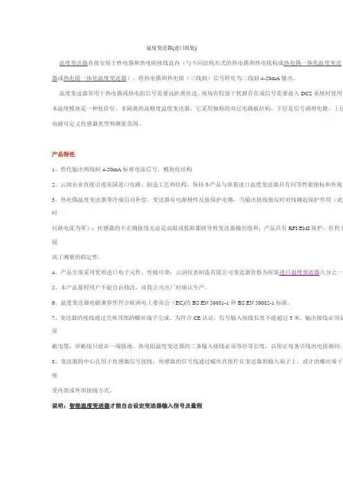
温度变送器(进口组装)温度变送器直接安装于热电偶和热电阻接线盒内(与不同结构形式的热电偶和热电阻构成热电偶一体化温度变送器或热电阻一体化温度变送器),将热电偶和热电阻(三线制)信号转化为二线制4-20mA输出。
温度变送器常用于热电偶或热电阻信号需要远距离传送、现场有较强干扰源存在或信号需要接入DCS系统时使用。
本温度模块是一种低价位、非隔离的高精度温度变送器,它采用独特的双层电路板结构,下层是信号调理电路,上层电路可定义传感器类型和测量范围。
产品特性1、性化输出两线制4-20mA标准电流信号,模块化结构2、云润企业直接引进英国进口电路、制造工艺和结构,保持本产品与原装进口温度变送器具有同等性能指标和外观。
3、热电偶温度变送器带冷端自动补偿。
变送器有电源极性反接保护电路,当输出接线接反时对线路起保护作用(此时回路电流为零);传感器的不正确接线无论是高限或低限都将导致变送器输出饱和;产品具有RFI/EMI保护,有利于提高了测量的稳定性。
4、产品全部采用优质进口电子元件,性能可靠;云润仪表制造有限公司变送器价格为原装进口温度变送器八分之一5、本产品量程用户不能自由修改,由我公司出厂时确认生产。
6、温度变送器电磁兼容性符合欧洲电工委员会(EC)的BS EN 50081-1和BS EN 50082-1标准。
7、变送器的接线通过壳体顶部的螺丝端子完成。
为符合CE认证,信号输入接线长度不能超过3米,输出接线必须是屏蔽电缆,屏蔽线只能在一端接地。
热电阻温度变送器的三条输入接线必须等径等长度,以保证每条引线的电阻相同。
8、变送器的中心孔用于传感器信号接线,传感器的信号线通过螺丝直接拧在变送器的输入端子上。
设计的螺丝端子接受内部或外部接线方式。
说明:智能温度变送器才能自由设定变送器输入信号及量程技术指标1、输入信号:铂电阻变送器—Pt100分度号铂电阻信号输入热电偶变送器—K型热电偶、E型热电偶、S型热电偶、B型等热电偶信号输入2、供电电压:10-30VDC3、负载电阻:0-500Ω4、输出信号:二线制4-20mA,最大30mA5、温度变送器精度:热电偶温度变送器精度:0.5%FS铂电阻温度变送器精度:0.2%FS7、温度稳定性:零点漂移标准0.05%FS/℃量程漂移标准0.002%FS/℃6、回路保护:带反向连接保护(防止电源正负极)8、温度变送器功耗:≤0.5W9、工作环境温度:工作温度:0-70℃储存温度:-40-70℃10、工作环境湿度:<95%RH(非冷凝)11、温度变送器重量:约35克12、外形及安装尺寸:热电偶温度变送器Ф45mm,H27mm,安装孔距36mm,安装孔Ф5.5m,接线柱内孔Ф2.5mm铂电阻温度变送器Ф42mm,H23mm,安装孔距33mm,安装孔Ф5.5m热电偶温度变送器接线图热电阻温度变送器接线图热电偶温度变送器选型表SWP—TC—□—□ / □| | |—————————————量程上限(20mA输出时对应的温度值)| |———————————————量程下限(4mA输出时对应的温度值)|——————————————————01 B分度号输入(量程在400-1800℃范围可选)|——————————————————02 S分度号输入(量程在0-1600℃范围可选)|——————————————————03 K分度号输入(量程在0-1300℃范围可选)|——————————————————04 E分度号输入(量程在0-1000℃范围可选)|——————————————————05 T分度号输入(量程在-199.9~320℃范围可选)|——————————————————06 J分度号输入(量程在0-1200℃范围可选)铂电阻温度变送器选型表SWP—TR—08 /□—□| | |—————————————量程上限(20mA输出时对应的温度值)| |————————————————量程下限(4mA输出时对应的温度值)||——————————————————08 Pt100输入(量程在-200~650℃范围可选)选型举例例1:SWP-TC-03-0/1300K型热电偶温度变送器,量程0-1300℃例2:SWP-TC-02-0/1600S型热电偶温度变送器,量程0-1600℃例4:SWP-TR-08-0/400铂电阻温度变送器,量程0-400℃例5:SWP-TR-10- -50/150铜电阻温度变送器,量程-50~150℃热电偶温度变送器实物彩图铂电阻温度变送器实物彩图Pt100铂电阻温度变送器如何修改量程Pt100温度变送器通常提供六种标准的量程范围供选择。
温度变送器选型
温度变送器选型先要选定输出信号,温度变送器输出信号通常有电流和电压两种,电流信号4-20mA,电压信号有0-2.5V、0-5V、0-10V 等,要根据上级仪表要求选定。
选定信号后确定量程,温度变送器的量程因为是跟输出信号对应的,选择的时候要以适合为度。
温度变送器精度也有很多种,通用的≤±0.2%,高精度的0.1℃&±0.05%甚至更高,选择满足要求的精度即可。
温度变送器还以可以选择现场显示功能,现场显示的同时也可以输出信号。
特殊环境还可以选择带HARRT协议智能温度变送器,调试比较方便。
温度变送器形式有一体化温度变送器和分体温度变送器,可以根据安装环境选择,一体化温度变送器有直插式、导轨式等安装方式,直插式可以安装在管道等任意空间,用螺纹、法兰固定,导轨式适合安装在机箱机柜里,用导轨固定。
分体式是指温度传感器和变送模块分开,安装现场温度过高或者安装空间有限一般选择分体式温度变送器。
温度变送器的材质也有不锈钢等很多种,可以根据安装环境选择。
规格尺寸多样,大小相差悬殊,HX-RS污泥堆肥专用的温度探杆可能有十几米高,而高精度微型温度变送器只有M10螺纹那么大。
温度变送器选型相对温度传感器要复杂一些,选型过程中只要多跟厂家沟通,就一定能选到满意的产品。
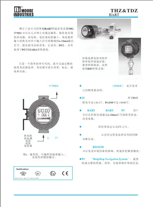
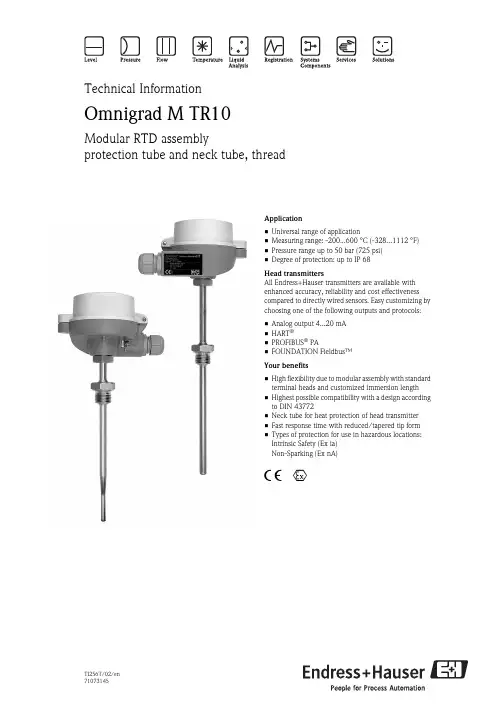
TI256T/02/en 71073145Technical InformationOmnigrad M TR10Modular RTD assemblyprotection tube and neck tube, threadApplication •Universal range of application•Measuring range: -200...600 °C (-328...1112 °F)•Pressure range up to 50 bar (725 psi)•Degree of protection: up to IP 68Head transmittersAll Endress+Hauser transmitters are available with enhanced accuracy, reliability and cost effectiveness compared to directly wired sensors. Easy customizing by choosing one of the following outputs and protocols:•Analog output 4...20 mA •HART ®•PROFIBUS ® PA•FOUNDATION Fieldbus™Your benefits•High flexibility due to modular assembly with standard terminal heads and customized immersion length •Highest possible compatibility with a design according to DIN 43772•Neck tube for heat protection of head transmitter •Fast response time with reduced/tapered tip form •Types of protection for use in hazardous locations:Intrinsic Safety (Ex ia)Non-Sparking (Ex nA)4 0TR102Endress+HauserFunction and system designMeasuring principleThe Resistance Temperature Detector (RTD) element has an electrical resistance with a value of 100 Ω at 0 °C (32 °F). It is commonly known as Pt100 and complies with IEC 60751. This resistance value increases at higher temperatures according to the characteristics of the resistor material (platinum). These kind of sensors are called Positive Temperature Coefficient elements (PTC).The coefficient is fixed with α = 0.00385 °C -1, calculated between 0 and 100 °C (32 and 212 °F), according to ITS90 (International Temperature Scale 1990).Wire wound platinum resistance thermometers (WW) consist of hair thin highly purified platinum wire double wound inside a ceramic carrier. This is then sealed top and bottom with a ceramic protective layer. Themeasurements achieved by these resistance thermometers are not only highly reproducible, but also show long term resistance/temperature characteristic stability within temperature ranges up to 600 °C (1112 °F). This sensor type is relatively large in its dimensions and is also not very resistant to vibration.Thin film platinum resistance thermometers (TF) consist of a precise amount of platinum which is vaporized under vacuum onto a ceramic substrate to a thickness of 1 μm. This is then protected by a glass layer. The advantages are: smaller dimensions than wire wound and greatly improved vibration resistance. Thin film resistances (TF) are flat, microscopic versions of the wire wound types (WW) with a measurement relevant difference:The temperature expansion behavior of the different layers of this structure leads to minimal mechanical stress. Temperature changes in thin film resistances (TF) cause the desired temperature relevant changes of the resistance as well as minimal tension stress related resistance changes. Through this the resistance/temperature characteristic of most thin film platinum resistance thermometers (TF) differs considerably from the standard characteristics at higher temperatures. Thin film resistances are therefore used for temperature measurement in ranges below 500 °C (932 °F).Measuring systemExample of an applicationA Built-in RTD assembly TR10 with head transmitter BRIA261 Field display–The display measures an analog measurement signal and indicates this on the display. The display is connected in a 4 to 20mA current loop and also derives its supply from the loop. The voltage drop is almost negligible (<2.5V). The dynamic internal resistance (load) makes sure that independently from the loop current, the maximum voltage drop is never exceeded. The analog signal at the input is digitalized, analyzed, and shown in the rear illuminated display. For details see Technical Information (see chapter "Documentation").CActive barrier RN221N–The RN221N active barrier (24 V DC, 30 mA) has a galvanically isolated output for supplying voltage to loop powered transmitters. The power supply has a wide-range input for mains power, 20 to 250V DC/AC,50/60Hz to be used in any electrical circuit. For details see Technical Information (see chapter "Documentation").TR10Endress+Hauser 3Equipment architectureEquipment architecture of the Omnigrad M TR10The Omnigrad M TR10 RTD assemblies are modular. The terminal head serves as a connection module for the protection armature in the process as well as for the mechanical and electrical connection of the measuring insert. The actual RTD sensor element is fitted in and mechanically protected within the insert. The insert can be exchanged and calibrated even during the process. Either ceramic terminal blocks or transmitters can be fitted to the internal base washer. Where required, threads or compression fittings can be fixed onto the protection armature.Measurement range-200 ... 600 °C (-328...1112 °F) according to IEC 60751Performance characteristicsOperating conditionsAmbient temperature12Insert (∅ 3 mm, 0.12 in) with mounted head transmitter, for exampleInsert (∅ 6 mm, 0.24 in) with mounted ceramic terminal block, for example 66a 6b Various tip shapes - detailed information see chapter ’tip shape’:Reduced or tapered for inserts with ∅ 3 mm (0.12 in)Straight or tapered for inserts with ∅ 6 mm (0.24 in)3Terminal headE Neck tube4Protection armatureL Immersion length5Threads as process connectionIL Insertion length = E + L + 10 mm (0.4 in)Terminal headTemperature in °C (°F)Without mounted head transmitter •Housing, material aluminum -40 to 100 ºC (-40 to 212 °F)•Housing, material polyamide -40 to 85 °C (-40 to 185 °F)With mounted head transmitter-40 to 85 °C (-40 to 185 °F)With mounted head transmitter and display -20 to 70 °C (-4 to 158 °F)TR10Process pressureThe pressure values to which the protection tube can be subjected at the various temperatures are illustratedby the figures below.Maximum permitted process pressure for tube diameter–Tube diameter 9 x 1 mm (0.35 in) -----------–Tube diameter 12 x 2.5 mm (0.47 in) - - - - - -A Medium water at T = 50 °C (122 °F)L Immersion lengthB Medium superheated steam at T = 400 °C (752 °F)P Process pressureMaximum flow velocityThe highest flow velocity tolerated by the protection tube diminishes with increasing immersion lengthexposed to the stream of the fluid. Detailed information may be taken from the figures below.Flow velocity depending on the immersion length–Tube diameter 9 x 1 mm (0.35 in) -----------–Tube diameter 12 x 2.5 mm (0.47 in) - - - - - -A Medium water at T = 50 °C (122 °F)L Immersion lengthB Medium superheated steam at T = 400 °C (752 °F)v Flow velocityShock and vibration resistance4g / 2 to 150 Hz as per IEC 60068-2-64Endress+HauserTR10Endress+Hauser 5AccuracyRTD corresponding to IEC 60751!Note!For measurement errors in °F, calculate using equations above in °C, then multiply the outcome by 1.8.Response timeTests in water at 0.4 m/s (1.3 ft/s), according to IEC 60751; 10 K temperature step changes:!Note!Response time for the sensor assembly without transmitter.Insulation resistanceInsulation resistance ≥100 M Ω at ambient temperature.Insulation resistance between each terminal and the sheath is tested with a voltage of 100 V DC.1)|t| = absolute value °CProtection tube DiameterResponse time Reduced tip ∅ 5.3 mm (0.2 in)Tapered tip∅ 6.6 mm (0.26 in) or ∅ 9 mm (0.35 in)Straight tip9 x 1 mm (0.35 in)t 50t 907.5 s21 s 11 s 37 s 18 s 55 s 11 x 2 mm (0.43 in)t 50t 907.5 s 21 s not available not available 18 s 55 s 12 x 2.5 mm (0.47 in)t 50t 90not available not available11 s 37 s38 s 125 sTR106Endress+HauserSelf heatingRTD elements are not self-powered and require a small current be passed through the device to provide a voltage that can be measured. Self-heating is the rise of temperature within the element itself, caused by the current flowing through the element. This self-heating appears as a measurement error and is affected by the thermal conductivity and velocity of the process being measured; it is negligible when an Endress+Hauser iTEMP ® temperature transmitter is connected.Calibration specificationsThe manufacturer provides comparison temperature calibration from -80 to +600 °C (-110 °F to 1112 °F) based on the International Temperature Scale of 1990 (ITS90). Calibrations are traceable to national and international standards. The calibration report is referenced to the serial number of the thermometer.MaterialTransmitter specificationsInsert-Ø:6 mm (0.24 in) and 3 mm (0.12 in)Minimum insertion length IL in mm (inch)Temperature rangewithout head transmitterwith head transmitter -80 °C to -40 °C (-110 °F to -40 °F)200 (7.87)-40 °C to 0 °C (-40 °F to 32 °F)160 (6.3)0 °C to 250 °C (32 °F to 480 °F)120 (4.72)150 (5.9)250 °C to 550 °C (480 °F to 1020 °F)300 (11.81)550 °C to 650 °C (1020 °F to 1202 °F)400 (15.75)Material Short description max. application temperature Features and benefits SS 316L/1.4404X2CrNiMo 17 13 2800 °C (1472 °F)•Austenitic, stainless steel •High corrosion resistance•High resistance at low temperatures•Optimal corrosion resistance in an acid, non oxydizing environment(e.g. phosphorous and sulphuric acids in low concentration and at low temperatures)•Not resistant to chloride at high temperatures SS 316Ti/1.4571X6CrNiMoTi 17 12 2800 °C (1472 °F)•Austenitic, stainless steel •High corrosion resistance•High resistance at low temperatures•Optimal corrosion resistance in an acid, non oxydizing environment (e.g. phosphorous and sulphuric acids in low concentration and at low temperatures)•Not resistant to chloride at high temperaturesHastelloy ® C276/2.4819NiMo 16 Cr 15 W 600 °C (1112 °F)•Specially high resistance against aggressive oxydizing and reducing media, even at high tempe-ratures.•Especially resistant against: sulphuric acid, high chloride contents, hot concentrated acetic acid chloride, chrome acetic acids, copper chloride, metal chloride TMT180PCP Pt100TMT181PCP Pt100, TC, Ω, mVTMT182HART ®Pt100, TC, Ω, mVTMT84 PA / TMT85 FF Pt100, TC, Ω, mVMeasurement accuracy0.2 °C (0.36 °F), optional 0.1 °C (0.18 °F) or 0.08%0.2 °C (0.36 °F) or 0.08%0.1 °C (0.18 °F)% is related to the adjusted measurement range (the larger value applies)Sensor current Ι ≤ 0.6 mAΙ ≤ 0.2 mAΙ ≤ 0.3 mAGalvanic isolation (input/output)-Û = 3.75 kV ACU = 2 kV ACTR10Endress+Hauser 7Transmitter long-term stability ≤ 0.1 °C/year (≤ 0.18 °F / year) or ≤ 0.05% / yearData under reference conditions; % relates to the set span. The larger value applies.System componentsFamily of temperature transmittersMeasurement assemblies with iTEMP ® transmitters are an installation ready solution to improve thefunctionality of temperature measurement by increasing accuracy and reliability when compared to direct wired sensors. Overall installation costs are lower than with direct wired sensors, since an inexpensive pair of signal (4 to 20 mA) wires can be run over long distances.PC programmable devices TMT180 and TMT181PC programmable head transmitters offer you extreme flexibility and help control costs with the ability to stock one device and program it for your needs. Regardless of your choice of output, all iTEMP ® transmitters can be configured quickly and easily with a PC. To help you with this task, Endress+Hauser offers free software ReadWin ® 2000 which can be downloaded from our website. Go to to download ReadWin ® 2000 today. Details see Technical Information (see chapter ’Documentation’).HART ® TMT182 head transmitterHART ® communication is all about easy, reliable data access and getting better information moreinexpensively. iTEMP ® transmitters integrate seamlessly into your existing control system and provide painless access to preventative diagnostic information.Configuration with a DXR275 or 375 hand-held or a PC with configuration program (FieldCare, ReadWin ® 2000) or configure with AMS or PDM. Details see Technical Information (see chapter ’Documentation’).PROFIBUS ® PA TMT84 head transmitterUniversally programmable head transmitter with PROFIBUS ® PA communication. Converting various input signals into a digital output signal. High accuracy over the complete ambient temperature range. Swift and easy operation, visualization and maintenance using a PC directly from the control panel, e. g. using operating software such as FieldCare, Simatic PDM or AMS. DIP switch for address setting, makes start up and maintenance safe and reliable.Benefits are: dual sensor input, highest reliability in harsh industrial environments, mathematic functions, thermometer drift monitoring, sensor back-up functionality, sensor diagnosis functions and sensor-transmitter matching using Callendar-Van Dusen coefficients. Details see Technical Information (see chapter ’Documentation’).!Note!The previous model PROFIBUS ® PA TMT184 head transmitter will be available for a transition time.FOUNDATION Fieldbus™ TMT85 head transmitterUniversally programmable head transmitter with FOUNDATION fieldbus™ communication. Converting various input signals into a digital output signal. High accuracy over the complete ambient temperature range. Swift and easy operation, visualization and maintenance using a PC directly from the control panel, e. g. using operating software such as ControlCare from Endress+Hauser or the NI Configurator from National Instruments.TR10Benefits are: dual sensor input, highest reliability in harsh industrial environments, mathematic functions,thermometer drift monitoring, sensor back-up functionality, sensor diagnosis functions and sensor-transmittermatching using Callendar-Van Dusen coefficients. Details see Technical Information (see chapter’Documentation’).Terminal heads All terminal heads have internal geometry according to DIN 43729, form B and thermometer connectionM24x1.5.All dimensions in mm (inch). All cable gland dimensions in the graphics are based on SKINTOP ST M20x1.58Endress+HauserTR10Endress+Hauser9TR1010Endress+HauserEndress+Hauser 11Protection tube All dimensions in mm (inches).Dimensions of the Omnigrad M TR10Tip shapeAvailable versions of protection tube tips (reduced, straight or tapered)AModel with terminal block mounted ∅ ID Insert diameterB Model with head transmitter mounted IL Insertion length = E + L + 10 mm (0.4 in)C Model with flying leads L Immersion lengthE Neck tube length ∅ X Protection tube diameterPos. No.Tip shape, L = Immersion length Insert Diameter M Reduced, L ≥ 70 mm (2.76 in)∅ 3 mm (0.12 in)R Reduced, L ≥ 50 mm (1.97 in)1)1)not with material Hastelloy ® C276/2.4819∅ 3 mm (0.12 in)S Straight∅ 6 mm (0.24 in)T Tapered, L≥ 90 mm (3.54 in)∅ 3 mm (0.12 in)W Tapered DIN43772-3G, L ≥ 115 mm (4.53 in)∅ 6 mm (0.24 in)12Endress+HauserWeightFrom 0.5 to 2.5 kg (1 to 5.5 lbs) for standard options.Process connectionSpare parts•A thermowell is available as spare part TW10 (see Technical Information in chapter ’Documentation’).•The RTD insert is available as spare part TPR100 (see Technical Information in chapter ’Documentation’).If spare parts are required, refer to the following equation: Insertion length IL = E + L + 10 mm (0.4 in)WiringWiring diagramsType of sensor connectionSpare partMaterial-No.Gasket M21-G½", copper 60001328Gasket M27-G¾", copper 60001344Gasket M33-G1", copper60001346Gasket set M24x1.5, aramid+NBR (10 pieces)60001329Endress+Hauser 13Installation conditionsOrientationNo restrictions.Installation instructionsInstallation examplesA - B: In pipes with a small cross section the sensor tip should reach or extend slightly past the center line of the pipe (= L).C - D:Tilted installation.The immersion length of the thermometer influences the accuracy. If the immersion length is too small then errors in the measurement are caused by heat conduction via the process connection and the container wall. If installing into a pipe then the immersion length must be at least half of the pipe diameter.•Installation possibilities: Pipes, tanks or other plant components•Minimum immersion length = 80 to 100 mm (3.15 to 3.94 in)The immersion length must be at least 8 times the protection tube diameter. Example: Protection tubediameter 12 mm (0.47 in) x 8 = 96 mm (3.8 in). Recommended standard immersion length according toDIN 43772: 120 mm (4.72 in)•ATEX certification: Always take note of the installation regulations!!Note!When operating in small nominal bore pipes it must be guaranteed that the protection tube tip is long enoughto extend past the pipe center line (see Pos. A and B). A further solution could be an angled (tilted) installation(see Pos. C and D). When determining the immersion length all thermometer parameters and the process tobe measured must be taken into account (e.g. flow velocity, process pressure).Neck tube length The neck tube is the part between the process connection and the housing. It is normally made of a tube withdimensional and physical characteristics (diameter and material) which are the same as of the tube in contactwith the medium.The connection situated in the upper part of the neck allows for orientation of the terminal head.As illustrated in the following figure, the neck tube length may influence the temperature in the terminal head.It is necessary that this temperature is kept within the limit values defined in the chapter "Operatingconditions".Heating of the terminal head consequent to the process temperature14Endress+HauserCertificates and approvalsCE Mark The device meets the legal requirements of the EC directives if applicable. Endress+Hauser confirms that thedevice has been successfully tested by applying the CE mark.Hazardous area approvals For further details on the available Ex versions (ATEX, CSA, FM, etc.), please contact your Endress+Hausersales organization. All relevant data for hazardous areas can be found in separate Ex documentation. If required,please request copies from us or your Endress+Hauser sales organization.Other standards and guidelines •IEC 60529:Degrees of protection by housing (IP-Code).•IEC 61010-1:Safety requirements for electrical measurement, control and laboratory instrumentation.•IEC 60751:Industrial platinum resistance thermometer•DIN43772:Protection tubes•EN 50014/18, DIN 47229:Terminal heads•IEC 61326-1:Electromagnetic compatibility (EMC requirements)PED approval The Pressure Equipment Directive (97/23/CE) is respected. As paragraph 2.1 of article 1 is not applicable tothese types of instruments, the CE mark is not requested for the RTD assembly destined for general use. Material certification The material certificate 3.1 (according to standard EN 10204) can be directly selected from the sales structureof the product and refers to the parts of the sensor in contact with the process fluid. Other types of certificatesrelated to materials can be requested separately. The "short form" certificate includes a simplified declarationwith no enclosures of documents related to the materials used in the construction of the single sensor andguarantees the traceability of the materials through the identification number of the thermometer. The datarelated to the origin of the materials can subsequently be requested by the client if necessary.Test on protection tube The pressure tests are carried out at ambient temperature in order to verify the resistance of the protection tubeto the specifications indicated by the norm DIN 43772. With regards to the protection tubes that do not complywith this norm (with a reduced tip, a tapered tip on a 9 mm (0.35") tube, special dimensions, ...), the pressureof the corresponding straight tube with similar dimensions is verified. The sensors certified for use in Ex Zones,are always tested to pressure according to the same criterions. Tests at different pressures can be carried outupon request. The liquid penetrant test verifies the absence of crevices on the weldings of the protection tube. Test report and calibration With regards to the tests and calibration, the "Inspection Report" consists of a compliance declaration for theessential points of the standard IEC 60751.The "Factory calibration" is carried out in an EA (European Accreditation) authorized laboratory ofEndress+Hauser according to an internal procedure. A calibration may be requested separately according to anEA accredited procedure (SIT calibration). Calibration is carried out on the thermometer insert.Endress+Hauser15Ordering informationProduct structure RTD thermometer TR10Approval:A Non-hazardous areaB ATEX II 1 GD EEx ia IICE ATEX II 1/2 GD EEx ia IICG ATEX II 1 G EEx ia IICH ATEX II 3 GD EEx nA IIK TIIS Ex ia IIC T4L TIIS Ex ia IIC T6Head; Cable Entry:B TA30A Alu, IP66/IP68; M20C TA30A Alu, IP66/IP68; NPT ½"D TA30A Alu, IP66/IP67; M12 plug PAE TA21E Alu, screw cap IP65; M12 plug PAF TA30A Alu+display, IP66/IP68; M20G TA30A Alu+display, IP66/IP68; NPT ½"H TA30A Alu+display, IP66/IP67; M12 plug PAJ TA20J 316L, IP66/IP67; M20K TA20J 316L, + display, IP66/IP67; M20M TA20J 316L, IP66/IP67; M12 plug PAN TA20R 316L, screw cap IP66/IP67; M20 silicone freeO TA30D Alu, high cover, IP66/IP68; M20P TA30D Alu, high cover, IP66/IP68; NPT ½"Q TA30D Alu, IP66/IP67; M12 plug PAR TA20R 316L screw cap IP66/IP67; M20S TA20R 316L screw cap IP66; M12 plugT TA30A Alu, IP66/IP67; 7/8" plug FFU TA30A Alu+display, IP66/IP67; 7/8" plug FFV TA30D Alu, IP66/IP67; 7/8" plug FF7TA20B PA black, IP65; M20Pipe Diameter; Material:A9 mm; 316L, DIN43772-2GB11 mm; 316L, DIN43772-2GD9 mm; 316Ti, DIN43772-2GE11 mm; 316Ti, DIN43772-2GF12 mm; 316Ti, DIN43772-2G/3GG9 mm; Alloy C276, DIN43772-2GH11 mm; Alloy C276, DIN43772-2GNeck Length E:180 mm, DIN43772-2G282 mm, DIN43772-3G3145 mm, DIN43772-2G4147 mm, DIN43772-3G8... mm9..... mm, as specifiedProcess Connection:BG Thread M20; 316TiBH Thread G ½" A; 316TiBJ Thread G 1" A; 316TiCA Thread G ½"; 316LCB Thread G ¾"; 316LCC Thread G 1"; 316LCD Thread NPT ½"; 316LCE Thread NPT ¾"; 316LHD Thread NPT ½"; Alloy C276HH Thread G ½" A; Alloy C276JA Thread R ½"; JIS B 0203, 316LJB Thread R ¾"; JIS B 0203, 316L16Endress+HauserTip Shape:M Reduced, L ≥ 70 mmR Reduced, L ≥ 50 mmS StraightT Tapered, L ≥ 90 mmW Tapered DIN43772-3G, L ≥ 115 mmImmersion Length L:A70 mmC120 mmD160 mmE220 mmF250 mmG280 mmH310 mmJ400 mmK580 mmX... mmY..... mm, as specified150 mm260 mm480 mm5100 mmHead Transmitter; Range:B TMT84 PAC Terminal blockD TMT85 FFF Flying leadsG TMT181 (PCP); temp. range to be specifiedH TMT182 (HART); temp. range to be specified2TMT180-A21 fix; 0.2 K, temp. range to be specified, Span limit -200/650 °C3TMT180-A22 fix; 0.1 K, temp. range to be specified, Span limit -50/250 °C4TMT180-A11 PCP; 0.2 K, temp. range to be specified, Span limit -200/650 °C5TMT180-A12 PCP; 0.1 K, temp. range to be specified, Span limit -50/250 °CRTD; wire; meas. range; class; validity:A1x Pt100 WW; 3; -200/600 °C; A: -200/600 °CB2x Pt100 WW; 3; -200/600 °C; A: -200/600 °CC1x Pt100 WW; 4; -200/600 °C; A: -200/600 °CF2x Pt100 WW; 3; -200/600 °C; 1/3B; 0/250 °CG1x Pt100 WW; 3; -200/600 °C; 1/3B; 0/250 °CY Special version, to be specified21x Pt100 TF; 3; -50/400 °C; A; -50/250 °C increas. vibr. resistance31x Pt100 TF; 4; -50/400 °C; A; -50/250 °C increas. vibr. resistance61x Pt100 TF; 3; -50/400 °C; 1/3B; 0/150 °C increas. vibr. resistance71x Pt100 TF; 4; -50/400 °C; 1/3B; 0/150 °C increas. vibr. resistanceMaterial Certificate:0Not needed1EN10204-3.1 Material2EN10204-3.1 Material, shortformTest Report:A Internal hydrost. pressure testB External hydrost. pressure testC Dye penetrant test, TW welding0Not neededTest/Calibration:A0, 100 °C, RTD-SignalB0, 100 °C, RTD-Signal, 4-20 mA/loopC0, 100 °C, RTD-Signal, 2 SensorsE0, 100, 150 °C, RTD-SignalF0, 100, 150 °C, RTD-Signal, 4-20 mA/loopG0, 100, 150 °C, RTD-Signal, 2 Sensors0Not neededTR10-← Order code (complete)This ordering information can give an overview about the available order options. The Endress+Hauser salesorganization can provide detailed ordering information and information on the order code.Endress+Hauser17DocumentationTechnical Information:•RTD Insert for Temperature Sensor Omniset TPR100 (TI268t/02/en)•Thermowell for temperature sensors Omnigrad M TW10 (TI261t/02/en)•Temperature head transmitter iTEMP® PCP TMT181 (TI070r/09/en)•Temperature head transmitter iTEMP® Pt TMT180 (TI088r/09/en)•Temperature head transmitter iTEMP® HART® TMT182 (TI078r/09/en)•Temperature head transmitter iTEMP® TMT84 PA (TI138r/09/en)•Temperature head transmitter iTEMP® TMT85 FF (TI134r/09/en)Hazardous area supplementary documentation:•Omnigrad TRxx RTD Thermometer ATEX II1GDor II 1/2GD (XA072r/09/a3)•Omnigrad TRxx, Omniset TPR100, TET10x, TPC100, TEC10x ATEX II 3GD EEx nA (XA044r/09/a3) Application example Technical information:•Field display RIA261 (TI083r/09/en)•Active barrier with power supply RN221N (TI073R/09/en)Instruments InternationalEndress+HauserInstruments International AGKaegenstrasse 24153 ReinachSwitzerlandTel.+41 61 715 81 00Fax+41 61 715 25 00info@TI256T/02/en/08.0871073145FM+SGML 6.0 ProMoDo。
如何选购正确的温度变送器选购温度变送器是一个关键的任务,因为它直接影响到测量和控制系统的准确性和可靠性。
下面是一些指导原则,帮助您正确选择温度变送器。
确定所需测量范围:首先,确定您需要测量的温度范围。
这将有助于确定所需的变送器类型。
温度变送器通常适用于广泛的温度范围,例如-200°C至+800°C。
选择合适的传感器类型:温度变送器通常与不同类型的传感器配对使用。
最常见的传感器类型包括热电偶和热电阻。
热电偶适用于高温应用,而热电阻适用于更广泛的温度范围。
根据您的具体需求选择合适的传感器类型。
考虑环境条件:在选择温度变送器时,必须考虑将其使用的环境条件。
特别注意以下因素:温度极限:如果变送器将在极限的温度条件下运行,例如高温或低温环境,确保选择符合这些要求的变送器。
一些高级型号具有绝缘材料和高温耐受能力。
湿度和防护等级:根据环境的湿度水平选择具有适当防护等级的变送器。
例如,如果变送器将在潮湿的条件下使用,选择具有IP67等级的防护。
考虑输出类型和接口:温度变送器可提供不同类型的输出信号,例如模拟信号(如4-20mA或0-10V)或数字信号(如RS485或Modbus)。
确保选择与您的控制系统兼容的输出类型。
校准和精度要求:对于需要高精度测量的应用,确保选择具有较高精度的变送器。
对于一些特殊应用,还可以要求定期校准。
考虑安装和维护便捷性:选择易于安装和维护的温度变送器。
注意选择具有适当连接器和插头的型号,以简化安装过程。
特殊功能和附加功能:某些温度变送器具有特殊功能和附加功能,如故障诊断功能、多点校准功能等。
根据您的特定需求,考虑这些额外的功能和特性。
参考用户评价和品牌信誉:在购买之前,参考用户评价和品牌信誉是非常有用的。
了解不同品牌的温度变送器的可靠性和性能,以便做出明智的选择。
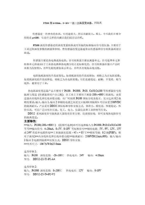
热电阻温度信号隔离变送分配器(一路PT100输入两路模拟信号输出DIN导轨安装式)主要特性:>>输入:Pt100(-200~+600℃)(范围可选择)也可以选择输入为Pt1000, Pt10,Cu50,Cu100等等>>输出信号:4~20mA,0~5V,0-10V 等标准信号>>辅助电源:5V、9V、12V、15V或24V直流单电源供电>>工业级温度范围: - 45 ~ + 85 ℃>>精度等级:0.2级(FSR%,相对于温度)>>内含线性化和长线补偿功能>>隔离耐压:2500VDC(1mA,60S),输入/输出1/输出2/电源四隔离>>安装方式:DIN35导轨安装>>外形尺寸:106.7x79.0x25.0mm图1 模块外观图概述:贝福科技研发的热电阻温度变送器产品主要用于Pt100,Pt1000,Pt10, Cu50,Cu100等传感器信号的隔离与变送(传感器需用户自己配),在工业上主要用于测量-200~+600℃的温度。
该变送器内有线性化和长线补偿功能,出厂时按照Pt100国标分度表校正,完全达到0.2级精度要求。
输入、输出1、输出2和辅助电源之间是完全隔离(四隔离),可以承受2500VDC的隔离耐压。
产品采用DIN35国际标准导轨安装方式,体积小、精度高,性能稳定、性价比高,可以广泛应用在石油、化工、电力、仪器仪表和工业控制等行业。
DIN12系列温度信号隔离放大器使用非常方便,仅需接好线,即可实现热电阻信号的隔离变送。
产品选型:DIN12 - Z□- T□- P□- A/V□输入类型:Z 温度范围:T 供电电源:P 输出型号:A或者V代码T 代码P 代码电流:A 代码电压:V 代码PT100 Z1 -20-100℃T1 24VDC P1 0-20ma A3 0-5V V1PT10 Z2 0-100℃T2 12VDC P2 4-20ma A4 0-10V V2Cu100 Z3 0-150℃T3 5VDC P3 用户自定义Au 1-5V V6Cu50 Z4 0-200℃T4 15VDC P4 用户自定义VuPt1000 Z5 0-400℃T5用户自定义Tu选型举例1:输入:Pt100 温度范围:-20~100℃供电电压:24V 输出:4-20mA型号:DIN12-Z1-T1-P1-A4选型举例2:输入:Pt1000 温度范围:0~200℃供电电压:12V 输出:0-10V型号:DIN12-Z5-T4-P2-V2通用参数:精度------- 0.2% (相对于温度)输入------- 三线、四线或两线热电阻信号,可选择Pt100, Pt1000, Pt10, Cu50, Cu100等热电阻。
一体化温度变送器选型样本
1.测量范围:首先要确定所需测量的温度范围,在选型时要选择与所需测量范围相匹配的一体化温度变送器。
常见的温度范围包括-200℃至+200℃、-50℃至+250℃、0℃至+400℃等。
2.准确度:准确度是一体化温度变送器的重要指标,通常表示为百分比或者绝对值。
准确度越高,测量结果越可靠。
选型时要注意所需的准确度符合实际需求。
3.输出信号:一体化温度变送器的输出信号通常有4-20mA、0-5V、0-10V等。
选型时要根据实际需要选择合适的输出信号类型。
4.电源供电:一体化温度变送器通常有两种供电方式,一种是DC24V 供电,另一种是AC220V供电。
根据实际情况选择合适的供电方式。
5.外观尺寸:一体化温度变送器的外观尺寸也是需要考虑的因素,特别是在安装空间有限的场合。
选型时要选择外观尺寸适合的一体化温度变送器。
6.防护等级:根据实际工作环境的要求,一体化温度变送器的防护等级也是需要考虑的因素。
常见的防护等级有IP65、IP67等。
7. 通讯接口:一体化温度变送器通常提供RS485、Modbus等通讯接口,用于与上位机或其他设备进行通讯。
根据实际需要选择合适的通讯接口类型。
8.附加功能:一体化温度变送器还可能具备一些附加功能,如报警输出、显示屏、远程控制等。
根据实际需求选择是否需要这些附加功能。
综上所述,选型一体化温度变送器需要考虑测量范围、准确度、输出信号、电源供电、外观尺寸、防护等级、通讯接口和附加功能等因素。
根据实际需求,选择合适的一体化温度变送器,可以满足工业自动化控制的需求。
1、范围1.1 本标准规定了公司多相流量计设计中常用的铂〔Pt〕热电阻温度变送器选型、设计、安装的具体技术要求和检验规程。
其它同类型温度变送器亦应参照使用。
1.2 本标准适用于二线制温度变送器的选型,不包括其他类型的温度变送器。
1.4 公司所有温度变送器的设计、采购、验收和施工均不得低于本标准的要求。
2 、根本工作原理热电阻温度变送器是利用感温材料的电阻值和温度之间的数学模型关系,将随温度变化而变化的电阻值转换为4~20mA的直流电流信号或1~5V的直流电压信号输出。
3、构成与功能一体化温度变送器主要由温度传感器、保护套管、变送器等局部组成。
传感器将温度的变化转换成电阻值的变化。
保护套管用于隔离工艺介质,保护电阻体。
变送器将变化的电阻值转换成为变化的4~20mA〔或1~5V〕模拟信号输出。
4、主要技术性能4、1铂热电阻根本误差:A级±〔0.15+0.002∣t∣〕℃B级±〔0.30+0.005∣t∣〕℃注:t为感温元件实测温度允许通过电流:<5mA常温绝缘电阻:环境温度为15--35℃和相对湿度不大于80%时热电阻感温元件和保护管之间的绝缘电阻应不小于100MΩ〔电压100V〕。
热电阻插入最小深度:一般不小于其保护管外径的8---10倍。
4、2 变送器精度等级:0. 2级负载电阻:250Ω供电电源:24VDC ±10%环境温度:-25~70℃输出信号:4~20mA〔或1~5V〕DC测量范围:0~100〔150〕℃防爆等级:根据使用要求选用。
5、选型原那么5、1 根据多相流量计装置的操作条件和使用场所,选用定型的、技术成熟可靠的产品。
对于新的产品,应在经过鉴定,确保质量的根底上选用。
5、2 在同一工程中,仪表品种规格不宜过多,并力求统一。
5、3 应根据现行的有关爆炸和火灾危险场所电气设备设计标准的规定,按一体化温度变送器安装场所的爆炸等级和爆炸性混合物的分类,确定其防爆形式及级别、组别。
温度变送器的基本原理是应用温度传感器进行温度检测,其温度传感器通常为热电阻、热敏电阻、集成温度传感器、半导体温度传感器等,然后通过转换电路将温度传感器的信号转换为标准电流信号或标准电压信号。
在选型方面可按照如下四个原则来选:
1 根据测量范围选择
可以参考其使用的温度传感器类型,参见温度传感器选型;
2 根据精度要求选择
可以参考其使用的温度传感器类型,参见温度传感器选型;
3 根据信号接口选择
可以选择4~20mA,0~10mA,0~20mA,0~5V,0~10V等,或数字/频率接口和其他接口;
4 根据结构形式和安装要求选择,如室内安装,选用壁挂型。
1、冶金上有一些测温场合,测温探头10天半月就不得不被烧坏,,,可以使唤俺村滴探头可互换超准温度变送器
2、温度不太高滴普通测温环境,测温探头不易被烧坏,,,可以使唤俺村滴一体化超准温度变送器
3、智能楼宇滴空调系统等,往往还需要根据室内外滴温差,来自动进行加热制冷控制,,,
可以使唤俺村滴超准双路温差变送器
4、只有模拟信号输出滴东东,才叫个变送器,,,把频率信号、通讯信号输出滴东东,叫个变送器,那是鸟人胡扯
计量局不答应
鸟人随地大小便,不穿裤衩打乱仗,是个特色
温度变送器呀,两线制4~20mA滴,抗干扰最拽
常见的温度变送器分为热电偶、热电阻、一体化的温度变送器:
一、热电偶信号远传用温度变送器由基准源、冷端补偿、放大单元、线性化处理、V/I转换、断偶处理、反接保护、限流保护等电路单元组成。
它是将热电偶产生的热电势经冷端补偿放大后,再帽由线性电路消除热电势与温度的非线性误差,最后放大转换为4~20mA电流输出信号以便于远传信号。
为防止热电偶测量中由于电偶断丝而使控温失效造成事故,变送器中还设有断电保护电路。
当热电偶断丝或接解不良时,变送器会输出最大值(28mA)以使仪表切断电源。
二、热电阻用变送器由基准单元、R/V转换单元、线性电路、反接保护、限流保护、V/I转换单元等组成。
测温热电阻信号转换放大后,再由线性电路对温度与电阻的非线性关系进行补偿,经V/I转换电路后输出一个与被测温度成线性关系的4~20mA的恒流信号。
三、一体化数显温度变送器与工业热电偶、热电阻配套使用,采用二线制传输方式(两根导线作为电源输入和信号输出的公用传线)。
一体化温度变送器将工业热电偶、热电阻信号转换成与输入信号或与温度信号成线性的4-20mA、0-10mA的输出信号。
可直接安装在热电偶、
热电阻的接线盒内与之形成一体化结构。
一体化温度传感器有二种:一种是直接是电阻信号,一种是加了一个温变。
选型注意事项:
1、输入信号、输出信号传输符合hart标准协议通信;
2、一体化温度变送器注意采取抗射频干扰措施;
3、温度变送器输入与输出相隔离,增加抗共模干扰能力,更适合与计算机连网使用,尤其是在高温环境下;
4、接线方式:根据不同形式有二线制、三线制、四线制等;
5、显示方式:LED、LCD可通过pc机或手持操作器设定的,使之显示现场温度、传感器值、输出电流和百分比例中的任一种参数;
6、工作电压:普通型号12v-35v,智能型12v-45v,最好是选择额定工作电压为24v 的
7、允许负载电阻:在额定工作电压时,负载电阻可在较宽范围内的优先选择。
8、注意选择好合适的温度、湿度环境:a:环境温度-25-+80℃(常规型) -25-+70℃(数显型) -25-+75℃(智能型) b:相对湿度:5%-95%
9、环境影响系数的影响:δ≤0.05%/℃,。
10、结构简单,无可动或弹性元件,可靠性极高,维护量少。
11、安装方便、调整方便;
12、特殊环境适用性:如高温、高压、强腐蚀等介质环境、振荡等,机械振动f≤50hz, 振幅≤0.15mm ;腐蚀气体或类似的环境;
13、防爆工作环境的,防爆方式选择:N 普通不防爆I 本安防爆 E 隔离防爆
14、预先确定安装方式:投入式、直杆式、螺纹式、法兰式.........
二、热电阻用变送器由基准单元、R/V转换单元、线性电路、反接保护、限流保护、V/I转换单元等组成。
测温热电阻信号转换
放大后,再由线性电路对温度与电阻的非线性关系进行补偿,经V/I转换电路后输出一个与被测温度成线性关系的4~20mA的恒流信号
选型注意事项:
1、输入信号、输出信号传输符合hart标准协议通信;
2、一体化温度变送器注意采取抗射频干扰措施;
3、温度变送器输入与输出相隔离,增加抗共模干扰能力,更适合与计算机连网使用,尤其是在高温环境下;
4、接线方式:根据不同形式有二线制、三线制、四线制等;
5、显示方式:LED、LCD可通过pc机或手持操作器设定的,使之显示现场温度、传感器值、输出电流和百分比例中的任一种参数;
6、工作电压:普通型号12v-35v,智能型12v-45v,最好是选择额定工作电压为24v 的
7、允许负载电阻:在额定工作电压时,负载电阻可在较宽范围内的优先选择。
8、注意选择好合适的温度、湿度环境:a:环境温度-25-+80℃(常规型) -25-+70℃(数显型) -25-+75℃(智能型) b:相对湿度:5%-95%
9、环境影响系数的影响:δ≤0.05%/℃,。
10、结构简单,无可动或弹性元件,可靠性极高,维护量少。
11、安装方便、调整方便;
12、特殊环境适用性:如高温、高压、强腐蚀等介质环境、振荡等,机械振动f≤50hz, 振幅≤0.15mm ;腐蚀气体或类似的环境;
13、防爆工作环境的,防爆方式选择:N 普通不防爆I 本安防爆 E 隔离防爆
14、预先确定安装方式:投入式、直杆式、螺纹式、法兰式.........
温度变送器选型原则
热电阻温度变送器是由基准单元、R/V转换单元、线性电路、反接保护、限流保护、V/I转换单元等组成。
测温热电阻信号转换放大后,再由线性电路对温度与电阻的非线性关系进行补偿,经V/I转换电路后输出一个与被测温度成线性关系的4~20mA的恒流信号。
温度变送器一般由基准源、冷端补偿、放大单元、线性化处理、V/I转换、断偶处理、反接保护、限流保护等电路单元组成。
它是将热电偶产生的热电势经冷端补偿放大后,再帽由线性电路消除热电势与温度的非线性误差,最后放大转换为4~20mA电流输出信号。
为防止热电偶测量中由于电偶断丝而使控温失效造成事故,变送器中还设有断电保护电路。
当热电偶断丝或接解不良时,变送器会输出最大值(28mA)以使仪表切断电源。
一体化温度变送器具有结构简单、节省引线、输出信号大、抗干扰能力强、线性好、显示仪表简单、固体模块抗震防潮、有反接保护和限流保护、工作可靠等优点。
一体化温度变送器的输出为统一的4~20mA信号;可与微机系统或其它常规仪表匹配使用。
也可用户要求做成防爆型或防火型测量仪表。
SBW系列温度变送器模块为24V供电、二线制的一体化变送器。
产品采用进口集成电路,将热电阻或热电偶的信号放大,并转换成4-20mA的输出电流,或0~5V的输出电压。
其中铠装变送器可以直接测量气体或液体的温度特别适用于低温范围测量,克服了冷凝水对测温所带来的影响.
一体化温度变送器一般由测温探头(热电偶或热电阻传感器)和两线制固体电子单元组成。
采用固体模块形式将测温探头直接安装在接线盒内,从而形成一体化的变送器。
一体化温度变送器一般分为热电阻和热电偶型两种类型。
以偶的使用经验来看,如果真的是DCS、FCS、PLC这样的控制系统,那么这个温度变送器最好还是不要使用。
一、因为现在的控制系统本身都带有热偶、热阻信号处理卡件,直接使用很方便,其温度冷端补偿也很集中,实际使用中出现故障处理也很方便。
二、在实际使用中其带屏蔽的两芯电缆的价格和带屏蔽的补偿导线的价格不相上下(这个具体价格虽然有所不同,但查不到那出,偶厂采购的基本上是一样的)。
因此直接把温度信号在控制室内处理不会因此施工成本增加。
三、一个温度变送器价格在几千左右(有的价格低,这个不同厂家质量不同),成本差不多的温度信号远传中间引入了温变,那么投资成本增加。
四、任何仪表都有精度,也就是都有误差,对于一个系统来说,中间环节越多,其误差的不确定性越大,越不准确。
五、温度变送器需要安装在现场,那么其安装环境的选择,防水、防尘、振动、干扰都要考虑,需要安装保温箱,这给施工带来难度。
六、温度变送器需要定期校准、维护,且因为温度测量中间环节的增多,其出现故障的几率变大,维护量大,出现故障的排除也更繁琐。
这个一体化的温度变送器,偶厂也使用过,总的来说还行,不过若是测量部件损坏,如热偶芯坏,或氧化老化,就得换新的,再者这个温度处理的小电路由于安装在很小的空间呢,各种连线很细小稍不注意就会弄断,维护困难,且互换性差。
因此逐渐又回到了普通的热偶测量中。
因为这个补偿导线的铺设真的很普遍,再者控制系统内都有直接温度检测的卡件。