MAX4367EGA中文资料
- 格式:pdf
- 大小:290.97 KB
- 文档页数:16
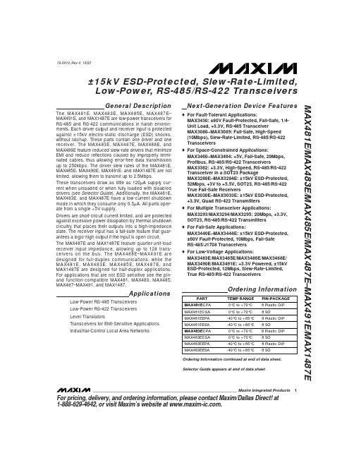
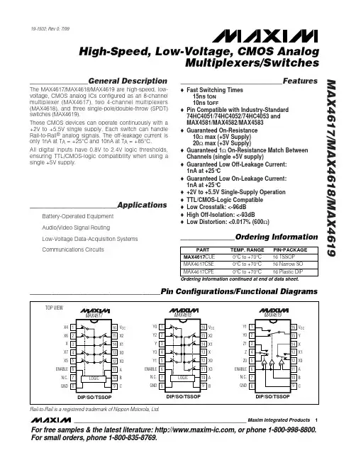
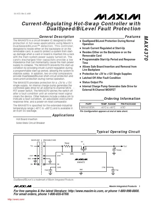
General DescriptionThe MAX4366/MAX4367/MAX4368 are bridged audio power amplifiers intended for devices with internal speakers and headsets. The MAX4366/MAX4367/MAX4368 are capable of delivering 330mW of continu-ous power into a 32Ωload, or 200mW into a 16Ωload with 1% THD+N from a single 5V supply.The MAX4366/MAX4367/MAX4368 bridged outputs elimi-nate the need for output-coupling capacitors minimizing external component count. The MAX4366/MAX4367/MAX4368 also feature a low-power shutdown mode,clickless power-up/power-down and internal DC bias generation. The MAX4366 is a unity-gain stable, program-mable gain amplifier. The MAX4367/MAX4368 feature internally preset gains of 2V/V and 3V/V, respectively.All devices are available in space-saving 8-pin TDFN and 8-bump UCSP™ chip-scale packages.ApplicationsCellular Phones Two-Way Radios PDAsHeadphones HeadsetsGeneral-Purpose AudioFeatures♦Drives 330mW into 32Ω(200mW into 16Ω)♦0.02% THD+N at 1kHz (120mW into 32Ω)♦Internal Bridged Configuration ♦No Output-Coupling Capacitors♦2.3V to 5.5V Single-Supply Operation ♦2mA Supply Current♦Low-Power Shutdown Mode♦Clickless Power-Up and Shutdown♦Thermal Overload Protection♦Available in TDFN and UCSP PackagesMAX4366/MAX4367/MAX4368330mW, Ultra-Small, Audio Power Amplifierswith Shutdown________________________________________________________________Maxim Integrated Products1Pin ConfigurationsOrdering InformationTypical Operating Circuit19-2338; Rev 5; 6/08Ordering Information continued at end of data sheet.Selector Guide and Functional Diagrams appear at end of data sheet.UCSP is a trademark of Maxim Integrated Products, Inc.For pricing, delivery, and ordering information, please contact Maxim Direct at 1-888-629-4642,or visit Maxim's website at .M A X 4366/M A X 4367/M A X 4368330mW, Ultra-Small, Audio Power Amplifiers with ShutdownABSOLUTE MAXIMUM RATINGSELECTRICAL CHARACTERISTICS(V CC = 5V, R L = ∞, R IN = R F = 30k Ω, C BIAS = 1µF to GND, SHDN = GND, IN+ = BIAS, T A = T MIN to T MAX , unless otherwise noted.Typical values are at T A = +25°C.) (Note 3)Stresses beyond those listed under “Absolute Maximum Ratings” may cause permanent damage to the device. These are stress ratings only, and functional operation of the device at these or any other conditions beyond those indicated in the operational sections of the specifications is not implied. Exposure to absolute maximum rating conditions for extended periods may affect device reliability.V CC to GND..............................................................-0.3V to +6V IN+, IN-, BIAS, SHDN to GND....................-0.3V to (V CC + 0.3V)Output Short Circuit to V CC or GND (Note 1).............Continuous Output Short Circuit (OUT+ to OUT-) (Note 1)...........Continuous Continuous Power Dissipation (T A = +70°C)8-Bump UCSP (derate 4.7mW/°C above +70°C)..........379mW 8-Pin TDFN (derate 24.4mW°C above +70°C)...........1951mWOperating Temperature Range ...........................-40°C to +85°C Junction Temperature......................................................+150°C Storage Temperature Range.............................-65°C to +150°C Lead Temperature (soldering, 10s).................................+300°C Bump Temperature (soldering) (Note 2)Infrared (15s)................................................................+220°C Vapor Phase (60s)........................................................+215°CMAX4366/MAX4367/MAX4368330mW, Ultra-Small, Audio Power Amplifierswith Shutdown_______________________________________________________________________________________3ELECTRICAL CHARACTERISTICS (continued)(V CC = 5V, R L = ∞, R IN = R F = 30k Ω, C BIAS = 1µF to GND, SHDN = GND, IN+ = BIAS, T A = T MIN to T MAX , unless otherwise noted.Typical values are at T A = +25°C.) (Note 3)Note 2:This device is constructed using a unique set of packaging techniques that impose a limit on the thermal profile the devicecan be exposed to during board-level solder attach and rework. This limit permits only the use of the solder profiles recom-mended in the industry-standard specification, JEDEC 020A, paragraph 7.6, Table 3 for IR/VPR and convection reflow.Preheating is required. Hand or wave soldering is not allowed.Note 3:All specifications are 100% tested at T A = +25°C; temperature limits are guaranteed by design.Note 4:Quiescent power-supply current is specified and tested with no load on the outputs. Quiescent power-supply currentdepends on the offset voltage when a practical load is connected to the amplifier.Note 5:Common-mode bias voltage is the voltage on BIAS and is nominally V CC /2.Note 6:Differential voltage gain for the MAX4366 is specified as an open-loop parameter because external resistors are used to setthe closed-loop gain. The MAX4367/MAX4368 contain internal feedback resistors that preset the differential voltage gain.Differential voltage gain is defined as (V OUT+- V OUT-) / (V IN - V BIAS ). All gains are specified over an output voltage range of 0.6V ≤V OUT ≤4.4V.Note 7:Specification applies to either output. An amplifier peak output current of 87mA is required to support an output load powerof 60mW for a 16Ωload, or 120mW for a 32Ωload.Note 8:Output power specifications are inferred from the output current test. For 60mW into a 16Ωload, I OUT(PEAK)is 87mA andV OUT(P-P)is 1.39V per amplifier. For 120mW into a 32Ωload, I OUT(PEAK)is 87mA and V OUT(P-P)is 2.77V per amplifier.Note 9:Guaranteed by design. Not production tested.Note 10:Measurement bandwidth for THD+N is 20Hz to 20kHz.Note 11:Power-up and shutdown times are for the output to reach 90% of full scale with C BIAS = 1µF.M A X 4366/M A X 4367/M A X 4368330mW, Ultra-Small, Audio Power Amplifiers with Shutdown 4_______________________________________________________________________________________Typical Operating Characteristics(Bridge-Tied Load, THD+N Bandwidth = 22Hz to 22kHz, C BIAS = 1µF.)TOTAL HARMONIC DISTORTION PLUS NOISEvs. FREQUENCYFREQUENCY (Hz)T H D +N (%)10k1k 1000.010.110.00110100kTOTAL HARMONIC DISTORTION PLUS NOISEvs. FREQUENCYFREQUENCY (Hz)T H D +N (%)10k1k 1000.010.110.00110100kTOTAL HARMONIC DISTORTION PLUS NOISEvs. FREQUENCYFREQUENCY (Hz)T H D +N (%)10k1k 1000.010.110.00110100kFREQUENCY (Hz)T H D +N (%)10k1k 1000.010.110.00110100kTOTAL HARMONIC DISTORTION PLUS NOISEvs. FREQUENCYFREQUENCY (Hz)T H D +N (%)10k1k 1000.010.110.00110100kTOTAL HARMONIC DISTORTION PLUS NOISEvs. FREQUENCYFREQUENCY (Hz)T H D +N (%)10k1k 1000.010.110.00110100kTOTAL HARMONIC DISTORTION PLUS NOISEvs. FREQUENCYFREQUENCY (Hz)T H D +N (%)10k1k 1000.010.110.00110100kTOTAL HARMONIC DISTORTION PLUS NOISEvs. FREQUENCYFREQUENCY (Hz)T H D +N (%)10k1k 1000.010.110.00110100kTOTAL HARMONIC DISTORTION PLUS NOISEvs. FREQUENCYFREQUENCY (Hz)T H D +N (%)10k1k 1000.010.110.00110100kTOTAL HARMONIC DISTORTION PLUS NOISEvs. FREQUENCYMAX4366/MAX4367/MAX4368330mW, Ultra-Small, Audio Power Amplifierswith Shutdown_______________________________________________________________________________________5FREQUENCY (Hz)T H D +N (%)10k1k 1000.010.110.00110100kTOTAL HARMONIC DISTORTION PLUS NOISEvs. FREQUENCYFREQUENCY (Hz)T H D +N (%)10k1k 1000.010.110.00110100kTOTAL HARMONIC DISTORTION PLUS NOISEvs. FREQUENCYFREQUENCY (Hz)T H D +N (%)10k1k 1000.010.110.00110100kTOTAL HARMONIC DISTORTION PLUS NOISEvs. FREQUENCYFREQUENCY (Hz)T H D +N (%)10k1k 1000.010.110.00110100kTOTAL HARMONIC DISTORTION PLUS NOISEvs. FREQUENCYFREQUENCY (Hz)T H D +N (%)10k1k 1000.010.110.00110100kTOTAL HARMONIC DISTORTION PLUS NOISEvs. FREQUENCYFREQUENCY (Hz)T H D +N (%)10k1k 1000.010.110.00110100kTOTAL HARMONIC DISTORTION PLUS NOISEvs. FREQUENCYFREQUENCY (Hz)T H D +N (%)10k1k 1000.010.110.00110100kTOTAL HARMONIC DISTORTION PLUS NOISEvs. FREQUENCYOUTPUT POWER (mW)T H D +N (%)3002001000.010.11101000.001400TOTAL HARMONIC DISTORTION PLUS NOISEvs. OUTPUT POWEROUTPUT POWER (mW)T H D +N (%)3002001000.010.11101000.001400TOTAL HARMONIC DISTORTION PLUS NOISEvs. OUTPUT POWERTypical Operating Characteristics (continued)(Bridge-Tied Load, THD+N Bandwidth = 22Hz to 22kHz, C BIAS = 1µF.)M A X 4366/M A X 4367/M A X 4368330mW, Ultra-Small, Audio Power Amplifiers with Shutdown 6_______________________________________________________________________________________Typical Operating Characteristics (continued)(Bridge-Tied Load, THD+N Bandwidth = 22Hz to 22kHz, C BIAS = 1µF.)TOTAL HARMONIC DISTORTION PLUS NOISEvs. OUTPUT POWEROUTPUT POWER (mW)T H D +N (%)3002001000.010.11101000.001400OUTPUT POWER (mW)T H D +N (%)3002001000.010.11101000.001400TOTAL HARMONIC DISTORTION PLUS NOISEvs. OUTPUT POWEROUTPUT POWER (mW)T H D +N (%)225150750.010.11101000.001300TOTAL HARMONIC DISTORTION PLUS NOISEvs. OUTPUT POWEROUTPUT POWER (mW)T H D +N (%)225150750.010.11101000.001300TOTAL HARMONIC DISTORTION PLUS NOISEvs. OUTPUT POWEROUTPUT POWER (mW)T H D +N (%)225150750.010.11101000.001300TOTAL HARMONIC DISTORTION PLUS NOISEvs. OUTPUT POWEROUTPUT POWER (mW)T H D +N (%)225150750.010.11101000.001300TOTAL HARMONIC DISTORTION PLUS NOISEvs. OUTPUT POWEROUTPUT POWER vs. SUPPLY VOLTAGESUPPLY VOLTAGE (V)O U T P U T P O W E R (m W )5.04.54.03.53.010020030040050002.55.5OUTPUT POWER vs. SUPPLY VOLTAGESUPPLY VOLTAGE (V)O U T P U T P O W E R (m W )5.04.54.03.53.010020040030050060002.5 5.5MAX4366/MAX4367/MAX4368330mW, Ultra-Small, Audio Power Amplifierswith Shutdown_______________________________________________________________________________________7OUTPUT POWER vs. LOADLOAD RESISTANCE (Ω)O U T P U T P O W E R (m W )1k1001010k501001502002500POWER DISSIPATION vs. OUTPUT POWEROUTPUT POWER (mW)P O W E R D I S S I P A T I O N (m W )1501005010020030040050000200POWER DISSIPATION vs. OUTPUT POWEROUTPUT POWER (mW)P O W E R D I S S I P A T I O N (m W )50100150200080604020100POWER DISSIPATION vs. OUTPUT POWEROUTPUT POWER (mW)P O W E R D I S S I P A T I O N (m W )5010015020004030201050GAIN AND PHASE vs. FREQUENCYFREQUENCY (Hz)G A I N (d B )/P H A S E (d e g )10M1M100k10k1k-160-140-120-100-80-60-40-20020406080-180100100MTypical Operating Characteristics (continued)(Bridge-Tied Load, THD+N Bandwidth = 22Hz to 22kHz, C BIAS = 1µF.)OUTPUT POWER vs. LOADLOAD RESISTANCE (Ω)O U T P U T P O W E R (m W )1k1005010015020025030035040045001010kM A X 4366/M A X 4367/M A X 4368330mW, Ultra-Small, Audio Power Amplifiers with Shutdown 8_______________________________________________________________________________________Typical Operating Characteristics (continued)(Bridge-Tied Load, THD+N Bandwidth = 22Hz to 22kHz, C BIAS = 1µF.)DIFFERENTIAL POWER-SUPPLY REJECTION RATIO vs. FREQUENCYFREQUENCY (Hz)P S R R (d B )100k10k1k100101M-70-50-30-100-80-20-40-60SUPPLY CURRENT vs. SUPPLY VOLTAGESUPPLY VOLTAGE (V)S U P P L Y C U R R E N T (m A )543210.51.01.52.02.500SUPPLY CURRENT vs. TEMPERATURETEMPERATURE (°C)S U P P L Y C U R R E N T (m A )603510-150.51.01.52.02.53.00-4085M A X 4366 t o c 36SUPPLY VOLTAGE (V)S H U T D O W N S U P P L Y C U R R E N T (μA )543215101520253035404500SHUTDOWN SUPPLY CURRENTvs. SUPPLY VOLTAGETEMPERATURE (°C)S U P P L Y C U R R E N T (μA )603510-1551015202530354045500-4085SHUTDOWN SUPPLY CURRENTvs. TEMPERATUREMAX4366/MAX4367/MAX4368330mW, Ultra-Small, Audio Power Amplifierswith Shutdown_______________________________________________________________________________________9Pin DescriptionDetailed DescriptionThe MAX4366/MAX4367/MAX4368 bridged audio power amplifiers can deliver 330mW into a 32Ωload, or 200mW into a 16Ωload, while operating from a single 5V supply. These devices consist of two high-output-current op amps configured as a bridge-tied load (BTL)amplifier (see Functional Diagram ). The closed-loop gain of the input op amp sets the single-ended gain of the device. Two external resistors set the gain of the MAX4366 (see G ain-Setting Resistors section). The MAX4367/MAX4368 feature internally fixed gains of 2V/V and 3V/V, respectively. The output of the first amplifier serves as the input to the second amplifier,which is configured as an inverting unity-gain follower in all three devices. This results in two outputs, identical in magnitude, but 180°out of phase.BIASThe MAX4366/MAX4367/MAX4368 feature an internally generated common-mode bias voltage of V CC /2 refer-enced to GND. BIAS provides both click-and-pop sup-pression and the DC bias level for the audio signal.BIAS is internally connected to the noninverting input of one amplifier, and should be connected to the nonin-verting input of the other amplifier for proper signal biasing (Typical Application Circuit ). Choose the value of the bypass capacitor as described in the BIAS Capacitor section.ShutdownThe MAX4366/MAX4367/MAX4368 feature a 35µA, low-power shutdown mode that reduces quiescent current consumption and extends battery life. Pulling SHDNhigh disables the device’s bias circuitry and drives OUT+, OUT-, and BIAS to G ND. Connect SHDN to GND for normal operation.Applications InformationBridge-Tied LoadThe MAX4366/MAX4367/MAX4368 are designed to drive a load differentially, a configuration referred to as bridge-tied load (BTL). The BTL configuration (Figure 1)offers advantages over the single-ended configuration,where one side of the load is connected to ground.Driving the load differentially doubles the output volt-age compared to a single-ended amplifier under similar conditions. The differential gain of the device is twice the closed-loop gain of the input amplifier. The effective gain of the MAX4366 is given by:Figure 1. Bridge-Tied Load ConfigurationM A X 4366/M A X 4367/M A X 4368The effective gains of the MAX4367 and MAX4368 are A VD = 2V/V and A VD = 3V/V respectively. Substituting 2x V OUT(P-P)for V OUT(P-P)into the following equations yields four times the output power due to doubling of the output voltage.Since the differential outputs are biased at midsupply,there is no net DC voltage across the load. This elimi-nates the need for DC-blocking capacitors required for single-ended amplifiers. These capacitors can be large, expensive, consume board space, and degrade low-frequency performance.Single-Ended ConfigurationThe MAX4366/MAX4367/MAX4368 can be used as sin-gle-ended amplifiers (Figure 2). The gain of the device in single-ended mode is 1/2 the gain in BTL configura-tion and the output power is reduced by a factor of 4.The single-ended gains of the MAX4367 and MAX4368are 1V/V and 1.5V/V, respectively. Set the MAX4366gain according to the Gain-Setting Resistors section.In single-ended mode, the load must be capacitively coupled to the device output to block the half-supply DC voltage from the load (see Output Coupling Capacitor section). Leave the unused output floating.Power DissipationUnder normal operating conditions, linear power ampli-fiers like the MAX4366/MAX4367/MAX4368 can dissi-pate a significant amount of power. The maximum power dissipation for each package is given in the Absolute Maximum Ratings section under Continuous Power Dissipation or can be calculated by the following equation:where T J(MAX)is +150°C and T A is the reciprocal of the derating factor in °C/W as specified in theAbsolute330mW, Ultra-Small, Audio Power Amplifiers with Shutdown 10______________________________________________________________________________________Figure 2. MAX4367 Single-Ended ConfigurationFigure 3. MAX4366 Typical Application CircuitMaximum Ratings section. For example, ΘJA of a TDFN package is 41°C/W.The increase in power delivered by the BTL configura-tion directly results in an increase in internal power dis-sipation over the single-ended configuration. If the power dissipation exceeds the maximum allowed for a given package, either reduce V CC , increase load impedance, decrease the ambient temperature, or add heat sinking to the device. Large output, supply, and ground traces improve the maximum power dissipation in the package.Thermal overload protection limits total power dissipa-tion in the MAX4366/MAX4367/MAX4368. When the junction temperature exceeds +165°C, the thermal pro-tection circuitry disables the amplifier output stage. The amplifiers are re-enabled once the junction temperature cools by +10°C. This results in a pulsing output under continuous thermal overload conditions avoiding dam-age to the part.Component SelectionGain-Setting ResistorsExternal feedback components set the gain of the MAX4366. Resistors R F and R IN (Figure 3) set the gainThe gain of the device in a single-ended configuration is half the gain of the BTL case. Choose R F between 10k Ωand 50k Ω. The gains of the MAX4367/MAX4368are set internally (Figure 4).Input FilterThe input capacitor (C IN ), in conjunction with R IN forms a highpass filter that removes the DC bias from an incoming signal. The AC-coupling capacitor allows the amplifier to bias the signal to an optimum DC level.Assuming zero source impedance, the -3dB point of MAX4366/MAX4367/MAX4368330mW, Ultra-Small, Audio Power Amplifierswith Shutdown______________________________________________________________________________________11Figure 4. MAX4367/MAX4368 Typical Application CircuitM A X 4366/M A X 4367/M A X 4368Choose R IN according to the G ain-Setting Resistors section. Choose the C IN such that f -3dB is well below the lowest frequency of interest. Setting f -3dB too high affects the low-frequency response of the system. Other considerations when designing the input filter include the constraints of the overall system, the actual frequency band of interest and click-and-pop suppres-sion. Although high-fidelity audio calls for a flat-gain response between 20Hz and 20kHz, portable voice-reproduction devices such as cellular phones and two-way radios need only concentrate on the frequency range of the spoken human voice (typically 300Hz to 3.5kHz). In addition, speakers used in portable devices typically have a poor response below 150Hz. Taking these two factors into consideration, the input filter may not need to be designed for a 20Hz to 20kHz response,saving both board space and cost due to the use of smaller capacitors.BIAS CapacitorThe BIAS bypass capacitor, C BIAS improves power-supply rejection ratio and THD+N by reducing power-supply noise at the common-mode bias node, and serves as the primary click-and-pop suppression mechanism. C BIAS is fed from an internal 25k Ωsource,and controls the rate at which the common-mode bias voltage rises at startup and falls during shutdown. For optimum click-and-pop suppression, ensure that the input capacitor (C IN ) is fully charged (ten time con-stants) before C BIAS . The value of C BIAS for best click-and-pop suppression is given by:In addition, a larger C BIAS value yields higher PSRR,especially in single-ended applications.Output-Coupling CapacitorThe MAX4366/MAX4367/MAX4368 require output-cou-pling capacitors only when configured as a single-ended amplifier. The output capacitor blocks the DC component of the amplifier output, preventing DC cur-rent flowing to the load. The output capacitor and the load impedance form a highpass filter with the -3dB point determined by:As with the input capacitor, choose the output capacitor (C OUT ) such that f -3dB is well below the lowest frequen-cy of interest. Setting f -3dB too high affects the low-frequency response of the system.In addition to click-and-pop suppression and frequency band considerations, the load impedance is another concern when choosing C OUT . Load impedance can vary, changing the -3dB point of the output filter. A lower impedance increases the corner frequency,degrading low-frequency response. Select C OUT such that the worst-case load/C OUT combination yields an adequate response.Clickless/Popless OperationProper selection of AC-coupling capacitors and C BIAS achieves clickless/popless shutdown and startup. The value of C BIAS determines the rate at which the mid-rail bias voltage rises on startup and falls when entering shutdown. The size of the input capacitor also affects clickless/popless operation. On startup, C IN is charged to its quiescent DC voltage through the feedback resis-tor (R F ) from the output. This current creates a voltage transient at the amplifier’s output, which can result in an audible pop. Minimizing the size of C IN reduces this effect, improving click-and-pop suppression.Supply BypassingProper supply bypassing ensures low-noise, low-distor-tion performance. Place a 0.1µF ceramic capacitor in par-allel with a 10µF capacitor from V CC to GND. Locate the bypass capacitors as close to the device as possible.Headphone ApplicationsThe MAX4366/MAX4368 can drive a mono headphone when configured as a single-ended amplifier. Typical 2-wire headphone plugs consist of a tip and sleeve. The tip is the signal carrier while the sleeve is the ground con-nection (Figure 5). Figure 6 shows the device configured to drive headphones. OUT+ is connected to the tip,delivering the signal to the headphone, while OUT-remains unconnected.330mW, Ultra-Small, Audio Power Amplifiers with Shutdown 12______________________________________________________________________________________Figure 5. Typical 2-Wire Headphone PlugWireless-Phone Headset ApplicationMany wireless telephones feature an earbud speaker/in-line microphone combination for hands-free use. One common solution is to use a BTL amplifier that drives the internal speaker and an earplug jack that mutes the inter-nal speaker by physically disconnecting OUT- when a headset is plugged in (Figure 7). The headset is driven single-endedly, requiring an output-coupling capacitor,C OUT , and resulting in a 4x reduction in output power.Adding Volume ControlThe addition of a digital potentiometer provides simple volume control. Figure 8 shows the MAX4367/MAX4368with the MAX5160 digital potentiometer used as an input attenuator. Connect the high terminal of the MAX5160 to the audio input, the low terminal to ground and the wiper to C IN . Setting the wiper to the top posi-tion passes the audio signal unattenuated. Setting the wiper to the lowest position fully attenuates the e the 100k Ωversion of the MAX5160.Layout ConsiderationsGood layout improves performance by decreasing the amount of stray capacitance and noise at the amplifi-er’s inputs and outputs. Decrease stray capacitance by minimizing PC board trace lengths, using surface-mount components and placing external components as close to the device as possible.UCSP ConsiderationsFor general UCSP information and PC layout considera-tions, please refer to the Maxim Application Note:UCSP–A Wafer-Level Chip-Scale Package.MAX4366/MAX4367/MAX4368330mW, Ultra-Small, Audio Power Amplifierswith Shutdown______________________________________________________________________________________13Figure 6. MAX4367 Headphone Application CircuitFigure 7. Headset with Internal Speaker Application CircuitFigure 8. MAX4367/MAX5160 Volume Control CircuitOrdering Information (continued)M A X 4366/M A X 4367/M A X 4368330mW, Ultra-Small, Audio Power Amplifiers with Shutdown 14______________________________________________________________________________________Pin Configurations (continued)*EP = Exposed paddle.+Denotes lead-free package.MAX4366/MAX4367/MAX4368Chip InformationTRANSISTOR COUNT: 669PROCESS: BiPOLAR330mW, Ultra-Small, Audio Power Amplifierswith Shutdown______________________________________________________________________________________15Functional DiagramsPackage InformationFor the latest package outline information and land patterns, go to /packages .M A X 4366/M A X 4367/M A X 4368330mW, Ultra-Small, Audio Power Amplifiers with Shutdown Revision HistoryMaxim cannot assume responsibility for use of any circuitry other than circuitry entirely embodied in a Maxim product. No circuit patent licenses are implied. Maxim reserves the right to change the circuitry and specifications without notice at any time.Maxim Integrated Products, 120 San Gabriel Drive, Sunnyvale, CA 94086 408-737-7600 ____________________16©2008 Maxim Integrated Productsis a registered trademark of Maxim Integrated Products, Inc.。