非接触式液位传感器使用说明分析
- 格式:doc
- 大小:906.50 KB
- 文档页数:7
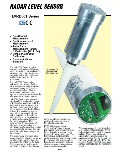
RadaR LeveL SenSoR U N on-ContactMeasurement U C ontinuous LevelMeasurement U P ulse RadarMeasurement Range: 0.254 to 15 m (10" to 50')U S imple PushbuttonCalibration U C ommunicationsStandard The LVRD500 Series a logical extension to the ultrasonic sensor series, is designed for applications requiring non-contact liquid level measurement, in which ultrasonic level measurement is not acceptable.The LVRD500 Series radar technology can be adjusted for variables such as materials to be measured, vessel configuration, and system interface. These sensors are ideal when vapor, dust, or a foaming surface prevents ultrasonic-wave measurements.LVRD500 Series radar sensors can detect the level under a layer of light dust or airy foam, but if the dust particle size increases, or if the foam or dust gets thick, they will no longer detect the liquid level. Instead, the level of the dust or foam will be measured. Internal piping, deposits on the antenna, multiple reflections, or reflections from the wall can interfere with the proper operation of the radar sensor. Other sources of interference are rat-holing and bridging of solids, as well as angled process material surfaces that can reflect the radar beam away from the receiver.The sensors use improved micro-wave-pulse technology to track any target material from the tip of the antenna to the bottom of the tank. Their power, pulse widths, and sensitivity depend on the distance of the target from the antenna and the dielectric constant of the reflecting material.LVRD500 sensors feature “echo marker” signal process-ing, making them among the most technologically advanced pulse radar systems on the market. This technology provides reliable, continuous pulse shapes unaffected by environmental factors such as temperature, vacuums, methane, steam, pressure, carbon dioxide, vapors, and condensation.The antenna comes in polypropylene or an optional high resistance PTFE that can help protect against material buildup. Simple mounting and push-button calibration make for easy installation. The sensor can be threaded directly into a 2 NPT metal or plastic flange. The tank must havea metal bottom to stop the microwave signal.LVRD501 SeriesLVRD501-RS232 shown smallerthan actual size.KFor high temperature PTFE, add suffix“-HT” to model number, for additional cost.For PTFE antenna, add suffix “-PTFE” to model number, for additional cost.For 316 SS housing, add suffix “-316SS” to model number , for additional cost.For 2" Tri-Grip sanitary mount and PTFE antenna add suffix “-S” to model number, for additional cost (only available on LVRD 501 series). Ordering Examples: LVRD504-RS232, 30.48 m (100') range, AC power with RS232.LVRD501-RS232, 15.24 m (50') range, DC power with RS232.than actual size.SPECIFICATIONS Accuracy: ±0.25% of maximumrange (in air)Power Options: AC: 115 Vac, 60 Hz or 230 Vac,50 Hz (±20%), 1.7 VA (4 wire)DC:**********************, 24 Vdc (3 wire)R load = (Vs–6)/24 mA Output: 4 to 20 mA, 6.1 µA resolution; 750 Ω (isolated on 4-wire models only); optional RS232 communications port Frequency: 5.8 GHz Loss of Echo Hold: 30 seconds,22 mA output Transmitter Power: 50 µW average Calibration: Pushbutton or optional programmable Diagnostics (Echo Profile): Via optional programmable port Antenna: Dielectric rod Operating Temperature Range:-40 to 60°C (-40 to 140°F)Installation Category: Class IIApprovals: FCC Part 15—low-power communication device Conduit Entry: 1⁄2NPT standard Mounting: 2 NPT, or optional sanitary2" Tri-Grip TM (Tri-Clamp ® compatible) (-S)Housing: Aluminum or optional 316 SS Ingress Protection: NEMA 4 (IP65)Communications Port: RS232 or RS485Options: -HT antenna (up to 204°C or 399°F), 316 SS housing (note: -HT available with PTFE units only)Dimensions:Housing: 102 Dia. x 216 mm L (4 x 8.5")Antenna: Max Dia. 38 x 259 mm L (4 x 8.5")LVRD501-RS232 shown smaller than actual size.。
非接触式液位物位计液位计安全操作及保养规程液位计是用于测量容器中液体或固体的高度而设计的仪器。
作为一种常用的测量设备,液位计有许多不同的类型,非接触式液位物位计是其中一种。
非接触式液位物位计通过远程红外测量技术,检测容器内物位,使用简便,操作方便,广泛应用于化工、食品、制药等领域。
在使用过程中,需要注意安全操作和保养,以保证设备长期稳定运行。
安全操作1.非接触式液位物位计应该安装在干燥、无腐蚀、通风良好的环境中,避免长期受到震动或者高温环境的影响。
避免产品受潮或者积水,以免导致设备损坏。
2.在进行设备接线时,应该仔细阅读液位计的接线图,确保接线正确,以避免因接线错误等原因造成设备故障。
在接线前,请务必断电并检查电气线路。
3.当设备投入使用后,应及时调整传感器的水平度,以保证其正常工作。
同时还要定期检查传感器光线是否有灰尘或者杂物,以免影响设备的准确测量。
4.在设备运行中,若出现异常情况,应及时停机排除故障。
严禁在设备启动时进行参数修改或开启或外部插入更高电压电源来代替标准电源。
不带核准的变通措施可能会导致设备性能下降或短期损坏,并且可能会影响单位的整体生产计划。
5.在设备维修或更换电子元件时,应该严格按照操作手册的说明进行操作,并注意带上防静电手套和使用防静电设备,以保证设备不受静电干扰或损坏。
若找不到对应的手册,或者操作不当,建议咨询专业的维修人员,以确保操作的安全和设备的正常使用。
保养规程1.非接触式液位物位计应该定期检查,以确保它的测量准确。
在定期检查中,可以将标准的管道液位计与非接触式液位物位计测量结果进行比对,如果发现测量结果出现误差,应该及时调整设备参数或更换元件,以使设备达到正常工作状态。
2.非接触式液位物位计应该保持干燥和清洁。
应该避免液位计受到化学腐蚀和机械损坏。
同时应注意对设备进行定期的清洁和维护,以保持设备质量和长期稳定运行。
3.如果长时间未使用液位计,应该将其存放在防潮防尘的地方,避免长时间曝晒和强光照射,以避免影响设备的性能。
非接触式液位计的优势分析液位计常见问题解决方法非接触式液位计拥有不动火,不清罐,安装维护和修理简单,牢靠性高以及精度高等特点,下面给大家介绍一下非接触式液位计的优势。
首先从测量方式上:非接触式液位计测量方非接触式液位计拥有不动火,不清罐,安装维护和修理简单,牢靠性高以及精度高等特点,下面给大家介绍一下非接触式液位计的优势。
首先从测量方式上:非接触式液位计测量方式不同与其他液位计(安装其他液位计时必需在容器上开孔,在容器内部测量液位),磁翻板液位计其特点是无需在容器上开孔,利用超声波处理技术,在容器外部就能够不间断地测出液面的精准明确高度。
其次,从安全性能以及成本掌控上看:非接触式液位计是真正的非接触式测量仪表,非接触式液位计的传感器安装在容器底部和侧壁;快速、牢靠和高精度容器容积测量;易于安装,无需破坏容器;在安装外测液位计的过程中无需设备停车;非接触式液位计无可移动部件,几乎不需要维护。
所以,非接触式液位计有其独特的优势,该仪表安装时不需要在罐壁上开孔安装传感器,仪表不接触容器内的液态介质。
有效解决了在强腐蚀、剧毒、高压力、易燃爆、高纯度、无杂菌感染等特别恶劣、苛刻条件下测量液位这一技术难题。
据了解非接触式液位计使用时极为安全牢靠,安装维护特别便利,是绿色环保仪表。
浮球式磁性液位计原理:在液体中放入一个空心的浮球,当液位变化时,浮球将产生与液位变化相同的位移,通过浮球中心的磁敏元件可用机械或电的方法来测得浮球的位移。
特点:精准明确度为±(1~2)%,其输出端有开关掌控和连续输出。
它结构简单、价格较低,一般不适用于高粘度的液体。
浮球液位计适用于测量工业和民用建筑水塔、水池、水箱、集水坑和工业槽罐等测量各种介质的液位,广泛应用于液位、化工、冶金、电力、造纸、食品及工业污水处理等部门。
改进方法:高粘度的液体可接受顶装大浮球,和侧装电动大浮球来测量。
雷达液位计基本原理:雷达液位计发射能量很低的极短的微波脉冲通过天线系统发射并接收,雷达波以光速运行,运行时间可以通过电子部件被转换成物位信号,利用特别的时间延长方法可以确保在极短时间内对物位做出稳定和精准明确的测量。
深圳市星科创科技有限公司Shenzhen XingKeChuang Technology Co., Ltd.XKC-C350(AC 100V-260V)-V1.6智能型非接触式液位控制器使用说明书XKC-C350(AC100V-260V)目录一、产品描述: (2)二、电气参数 (2)三、信号输入和继电器输出对应图 (3)四、产品选型(AC100V-260V) (3)五、基本功能介绍 (3)六、推荐安装方法说明 (4)七、推荐接线及应用示意图 (4)八、产品尺寸及实物图 (10)九、其它注意事项 (11)十、产品保修条款和说明 (11)十一、说明书版本 (12)一、产品描述:XKC-C350智能型非接触式液位控制器和XKC-Y25液位探头实现液位高低控制功能:当容器液位过少时触发低液位传感器发出的低液位报警信号触发,C350控制器闭合继电器启动水泵加液位,液位达到一定高度时,高液位传感器发出信号触发C350控制器断开继电器,自动停止水泵工作,这样循环工作。
从而实现容器液位高低自动控制的功能,保持容器液位稳定。
二、产品特点1.AC100V~260V宽电压供电。
2.继电器干节点输出,可适用多种负载控制。
3.控制多样化,可手动或自动模式控制水泵。
4.安装简单方便,可螺丝定位安装也可以电箱轨道安装。
二、电气参数型号XKC-C350 名称C350智能型非接触式液位控制器输入电压AC100V-260V,50/60Hz感应头工作电压DC12V工作电流工作电流≤110 mA,静态耗电流≤20mA。
负载功率供电电压为100V时:最大功率700W。
供电电压为260V时:最大功率1600W。
如需控制负载超过此极限参数时请加装中间继电器报警输出800W(阻性负载)常开常闭输出输出方式常开/常闭输出输入信号低位感应信号输入;高位感应信号输入;感应头接口电压DC12V工作温度-20~105℃外形尺寸87*54*59三、信号输入和继电器输出对应图输入信号 负载输出报警信号状态 报警输出 低位为0,高位为0 常开端(NO )闭合,常闭端(NC )断开 循 环低位为0,高位为1常开端(NO )闭合,常闭端(NC )断开低位为1,高位为0 (水位上升)常开端(NO )闭合,常闭端(NC )断开高位溢出为1常开端(NO )闭合,常闭端(NC )断开低位为1,高位为1 常开端(NO )断开,常闭端(NC )闭合 报警状态,负载输出:常开断开,常闭闭合 (继电器断开状态,负载断开进入保护)低位为1,高位为0 (水位下降)常开端(NO )断开,常闭端(NC )闭合注:0代表探头检测不到水输出低电平0V 电压,1代表探头检测到有水输出高电平12V 电压。
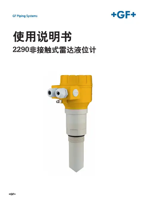
使用说明书2290非接触式雷达液位计2原版使用说明书请遵循此使用说明书该使用说明书是产品的一部分,是安全概念的重要元素。
④请阅读并遵循此使用说明书。
④请始终保持使用说明书的可用性。
④请将该使用说明书传递给产品的所有后续用户。
3目录原版使用说明书 (3)目录 (3)1 预期用途 (6)2 关于本文 (6)2.1 警告 (6)3 安全与责任 (6)4 运输与存储 (7)5 设计与功能 (7)5.1 功能 (7)5.2 工作原理 (7)6 技术数据 (8)6.1 尺寸 (9)6.2 确定最大测量范围 (10)7 安全操作条件 (11)8 安装 (11)8.1 安装固定 (11)8.2 接线 (13)8.2.1 设备接线 (14)8.2.2 确定适当的电源电压 (15)8.3 使用手持仪器进行回路电流的检测 (15)9 设置2290液位计 (16)9.1 显示单元 (17)9.1.1 信息画面 (18)9.1.2 回波图 (19)9.2 使用显示模块进行设置 (19)9.2.1 设置界面的组成 (18)9.2.2 菜单结构 (20)9.3 可设置功能的描述 (21)9.3.1 基本测量设置 (19)9.3.2 输出设置 (22)9.3.3 数字输出 (21)9.3.4 优化 (23)9.3.5 计算 (23)9.3.6 检修 (28)10 维修及维护 (28)11 附件 (28)12 错误代码 (29)13 2290 W-100参数表 (30)14 菜单图 (34)15 拆卸 (36)16 弃置处理 (36)456预期用途使用说明书GF 2290型非接触式微波液位计提供了最先进的,工业过程自动化领域的新一代测量技术。
2290广泛适用于诸如食品、能源、制药以及化工等应用,其毫米级精度范围和高测量稳定性甚至适用于海军应用,是测量液体、浆液、乳液以及其他化学品的理想解决方案。
2290可对倾向于产生蒸气的物质,或带有气体层的液体,提供优秀的非接触式液位测量。
XKC-Y26-xxx智能型非接触外贴式管道专用系列(2016-02-19)液位传感器使用说明书深圳市星科创科技有限公司Shenzhen XingKeChuang Technology Co., Ltd.一、产品概述智能型非接触式液位感应器(以下简称液位感应器)采用了先进的信号处理技术及高速信号处理芯片,突破了容器壁厚的影响,实现了对密闭容器内液位高度的真正非接触检测。
液位传感器(探头)安装于被测容器外壁的上下方(液位的高位与低位),非金属容器无需对其开孔、安装简易、不影响生产。
可实现对高压密闭容器内的各种有毒物质﹑强酸﹑强碱及各种液体的液位进行检测。
液位感应器对液体介质和容器的材质无特殊要求,可广泛使用。
XCK-Y26-xxx系列产品专门针对非金属管道液位检测而开发,本系列液位感应器分三种信号输出接口,分别为高低电平输出接口、NPN输出接口、PNP输出接口;三种型号输出方式分别对应以下三种型号:高低电平输出接口——型号:XKC-Y26-VNPN输出接口——型号:XKC-Y26-NPNPNP输出接口——型号:XKC-Y26-PNP二、产品特性⏹XCK-Y26-xxx系列传感器,适用于非金属管道外壁而无需与液体直接接触,不会受到强酸强碱等腐蚀性液体的腐蚀,不受水垢或其他杂物影响。
⏹智能化液位基准调整及液位记忆功能,液位状态显示方式,可实现多点串联接线;可支持高低电平输出、NPN、PNP信号输出(选型时与厂家说明即可)。
⏹检测准确稳定,可检测沸水液面。
⏹纯电子电路结构,非机械工作方式,性能稳定寿命耐久。
⏹高稳定性,高灵敏度,刚干扰能力强,不受外界电磁干扰,针对工频干扰及共模干扰有做特殊处理,以兼容市面上所有的5~24V电源适配器。
⏹强大兼容性,穿透各种非金属材质的容器管道,如塑料、玻璃、陶瓷等容器,感应管壁厚度可达20mm;适用于各种曲面、弧形、圆柱形的容器或管道的液位检测。
⏹电压范围宽(5~24V),适合连接各种电路及产品应用。
液位计传感器操作说明液位计传感器是一种用于测量液体容器内液位高度的设备。
它在工业生产和实验室测试等领域广泛应用,既能提高工作效率,又能保障生产安全。
本篇文章将详细介绍液位计传感器的操作方法,以帮助用户正确、高效地使用该设备。
一、设备介绍液位计传感器通常由以下几个部分组成:1. 传感器主体:用于监测液位变化的核心部件。
2. 连接线:将传感器与其他设备(如数据显示器或控制系统)连接起来。
3. 控制器:负责接收传感器信号,并进行处理和控制。
二、准备工作在进行液位计传感器操作之前,需要做一些准备工作:1. 检查设备:确保传感器主体、连接线和控制器完好无损。
2. 准备液体容器:清洁容器,确保内部干净,无影响测量的杂质。
三、连接传感器和控制器1. 使用连接线将传感器主体与控制器连接。
确保连接线插头与接口相匹配,并牢固连接。
2. 检查连接是否牢固,确保信号传输正常。
四、安装传感器1. 将传感器主体固定在液体容器上。
可根据容器类型选择适合的固定方式,如磁吸固定、螺纹固定等。
2. 确保传感器与容器接触良好,无松动或摩擦。
五、校准传感器在开始正式测量之前,需要对传感器进行校准,以确保测量结果的准确性和可靠性。
1. 将液位计传感器放置在已知液位位置,并记录对应的信号数值。
2. 根据校准曲线或参数表,调整传感器控制器中的相应参数,使其与实际液位保持一致。
六、启动传感器1. 打开控制器电源,并确认显示屏上出现相关信息。
若显示异常或无显示,请检查设备连接是否正确。
2. 按照设备说明书操作,设置传感器测量范围和采样周期等参数。
七、测量液位1. 将待测液体注入容器中,并等待液位稳定。
确保液位超出传感器测量范围,以保证测量的准确性。
2. 传感器将实时监测液体液位,并将信号发送给控制器。
根据控制器的设定,可以通过显示屏或其他设备查看液位数据。
八、数据处理与控制1. 控制器可将液位数据转化为可视化形式,如图表或数字显示。
用户可通过观察数据分析液位变化趋势。
XKC-Y25-V-V1.6Non-contact liquid level sensor instruction manual(Intelligent externally attached liquid level detection products)XKC-Y25-Vtable of Contents1st. Overview (2)2nd.Product Features (2)3rd.Product Applications (2)4th.Product parameter (3)5th.product selection (3)6th. Clearance requirements (3)7th. Installation method (4)8th.Application environment (9)9th. output principle and recommended wiring method (9)10th. Sensitivity adjustment (10)11th. Product size and physical map (11)12th.Other matters needing attention (12)13th.Troubleshooting: (12)14th.Product warranty terms and instructions (13)15th. Manual version (14)1st. OverviewThe intelligent non-contact liquid level sensor (hereinafter referred to as the liquid level sensor) adopts advanced signal processing technology and high-speed signal processing chip, which breaks through the influence of container wall thickness and realizes a true non-contact type of liquid level height in a closed container Detection. The liquid level sensor (probe) is installed on the upper and lower sides of the outer wall of the container to be measured (the high and low levels of the liquid level). The non-metallic container does not need to be opened, and the installation is simple and does not affect production. It can detect the liquid level of various liquid toxic substances, strong acids, strong alkalis and various liquids in high-pressure airtight containers. The liquid level sensor has no special requirements for the material of the liquid medium and non-metallic container, and can be widely used. XKC-Y25-XXX series products are specially developed for non-metallic container liquid level detection. This series of liquid level sensors are divided into four signal output control methods, namely high and low level output interface, NPN output interface, PNP output interface, RS485 Output interface; the four signal output modes correspond to the following four models:Serial number type number signal interface1 XKC-Y25-V High and low level output interface2 XKC-Y25-NPN NPN output interface3 XKC-Y25-PNP PNP output interface4 XKC-Y25-RS485 RS485 output interface2nd.Product Features1. XKC-Y25-XXX non-contact liquid level sensor is suitable for non-metallic containers. The product detects the liquid through the detection signal through the non-metallic container and the outer wall of the pipeline, without direct contact with the liquid, and will not be subject to strong acid, Corrosion damage caused by corrosive liquids such as strong alkalis is not affected by scale or other debris, and it can be completed to detect whether there is liquid inside the container or pipeline.2. It can support high and low level output, NPN, PNP signal output (please refer to the manufacturer's instructions when selecting the model).3. The detection liquid level is accurate and stable, and cold, hot and boiling liquids can be detected.4. Pure electronic circuit structure, non-mechanical working mode, stable performance and long lasting service life.5. High stability, high sensitivity, strong anti-interference ability, free from external electromagnetic interference, special treatment for power frequency interference and common mode interference, to be compatible with all 5-24V power adapters on the market.6. It has a wide range of application and strong sensing capability. It can penetrate and detect the liquid level in various non-metallic containers, such as plastic, glass, ceramics and other containers. The sensing distance (container wall thickness) can reach 20mm; liquid, powder, Particles can be detected.7. Open collector output mode, wide voltage range (5-24V), suitable for connecting various circuits and product applications.3rd.Product ApplicationsThe intelligent non-contact liquid level sensor uses the inductive capacitance of water to detect the presence of liquid. When there is no liquid close to the sensor, the sensor has a certain static capacitance to the ground due to the presence of distributed capacitance on the sensor. When the liquid level is slow When the sensor is slowly raised, the parasitic capacitance of the liquid will be coupled to the static capacitance of the sensor, making the capacitance value of thesensor larger. The changed capacitance signal is then input to the control IC for signal conversion, and the changed capacitance is converted into a circuit signal The MCU calculates and judges the degree of the change in the analog quantity. When the change exceeds a certain threshold, it is considered that the liquid level has reached the sensing point. 4th.Product parameterProject name ParametersProduct model XKC-Y25-VSupply voltage(Vin)(DC 5V-24V)Output mode High and low levelPower ripple requirements ≤200 mVelectric current ≤5mAResponse time 500mSWorking temperature -20~105℃humidity5%~100%Induction thickness(Sensitivity) range≤20mm(Container wall thickness)Liquid level accuracy±1.5mmLine length 500MM(±10MM)(Bulk can be customized)Terminal sequence Brown (power supply positive), yellow (signal output) Blue (power negative), black (COM terminal)Material PC V0 Fireproof materialWaterproofperformanceIP67Safety standardcertificationCEEnvironmentalprotection certificationROHS-2.05th.product selectionHigh and low level————Model: XKC-Y25-V (DC 5V-24V)6th. Clearance requirementsRequirements for the clearance between the contact surface of the sensor (or probe) and the outer wall of the container The contact surface of the sensor (or probe) and the outer wall of the container should be tightly pasted with AB or other solid-resistant glue. If there are special requirements, the gap should be less than 0.5mm, preferably no gap, otherwise it may affect the measurement accuracy.7th. Installation methodThe following is the installation method of XKC-Y25 series products, the installation method of other models is the same.(1) Requirements and installation methods of the tested container The tested containers are divided into 3 categories according to their materials:The first category: insulating material containerContainers made of non-metallic materials with flat surface, uniform thickness, compact materials, and good insulation properties; such as glass, plastic, non-absorbent ceramics, acrylic, rubber and other aterials or their composite materials.installation method:1. If the container wall where the measuring probe is installed is of multi-layer material, the layers should be in close contact with each other without bubbles or gas interlayers. The inner and outer surfaces of the container wall should be flat.2. Wall thickness: 0-20mm3. Tank type: spherical tank, horizontal tank, vertical tank, etc.4. The installation method of this kind of material container is shown in Figure 1;The probe can be pasted and fixed with glue or fixed on the outer wall of the container with a non-metal bracket.Try to avoid metal and other parts where the probe is installed, so as not to affect the detection.The position where the probe is installed should try to avoid the position where the liquid flows.There should be no silt or other debris inside the container facing the low-level probe, so as not to affect the detection;Figure 1-1 The top image of a non-metallic container of a probe installation diagramFigure 1-2 The above diagram of the installation of two probes in a non-metallic containerThe second category: metal conductive material containerContainers made of metal or other conductive materials; such as stainless steel, copper, aluminum alloy or materials with electroplated metal layers on the surface. Because capacitive sensors are sensitive to all conductive objects, this type of container cannot be directly attached to the outer wall of the container; therefore, for containers of this type of material, holes need to be made on the side of the container. The installation method is as follows.installation method1. Prepare two rubber plugs and the necessary tools for opening threaded holes;2. Two threaded holes are opened in the high position and the low position respectively, and the hole diameter matches the size of the rubber plug;3. Put a rubber plug on the threaded hole and tighten it to check for water leakage, and add glue to seal if necessary;4. Paste the sensor on the rubber plug with glue and fix it with the bracket. After the glue has solidified, remove the bracket. The installation of the metal container is shown in Figure 2.Figure 2-1 Installation diagram of a sensor in a metal containerFigure 2-2 Schematic diagram of installation of 2 sensors in a metal containerThe third category: non-metallic materials that absorb waterContainers made of ceramics, tiles, bricks, tiles, cement, wood boards and other materials are insulators or weakly conductive. This kind of container may not be detected when it is close to the liquid level sensor when it is dry and without water, but when the container is filled with water, the container wall will absorb water, causing the container wall to become a conductor; even if the container is empty When the sensor is close to the container wall, the signal will also be detected.If the sensor is to be used on a container of this type of material, the installation method should be in accordance with the installation method of a metal container. For the installation method, see "Class 2: Metal Conductive Material Container" and Figure 2; or use an external pipe to install. External pipes are divided into external non-metallic pipes and external metal pipesThe installation method of external non-metallic pipes is shown in Figure 3-1 and Figure 3-2. The installation method of external metal pipes is shown in Figure 4-1 and Figure 4-2..Figure 3-1 Schematic diagram of the installation of a sensor in an external non-metallic pipeFigure 3-2 Schematic diagram of the installation of two sensors on external non-metallic pipesFigure 4-1 Schematic diagram of the installation of 1 sensor in an external metal pipeFigure 4-2 Schematic diagram of installation of two sensors on external metal pipesFigure 5 The sensor is installed on the iron pipe with the three-prong joint (the installation diagram of metal andwater-absorbing container)The sensor is installed on a non-metallic water pipe with a smaller diameter8th.Application environment1. XKC-Y25-V, XKC-Y25-NPN/PNP (5-12V)It is only applicable under the conditions of good EMC environment. For example, the connection with MCU, and some simpler load applications, such as LED indicator lights, piezoelectric buzzer, etc. And there is no high-power capacitive and inductive load and harsh electromagnetic environment on the power bus.2. XKC-Y25-NPN/PNP (24V), Y25-RS485 (24V)This model is carefully designed for harsh industrial environments. Added professional EMC components, such as spike absorption, electromagnetic compatibility, and transient suppression and surge protection. It can be directly connected to PLC, electromagnetic relay, etc. It has a very strong anti-interference ability and is suitable for all harsh industrial application environments.9th. output principle and recommended wiring methodHigh and low level output drive small electric relay (coil current ≤100mA) Product Applications:1.When the black line is suspended, it is positive output:When liquid is sensed, the transistor cuts off and outputs a high level, and the relay does not pull in when it is powered off;When no liquid is sensed, the transistor turns on and outputs a low level, and the relay is energized and closed.2.When the black wire is grounded (connected to the negative pole of the power supply 0V), it is a reverse output: When liquid is sensed, the transistor turns on and outputs a low level, and the relay is energized and closed;When no liquid is sensed, the transistor cuts off and outputs a high level, and the relay does not pull in when it is powered off.10th. Sensitivity adjustmentIf the liquid level cannot be detected or the distance between the detected liquid level and the Y25 sensor is deviated, Open the back cover of the sensor and use a small screwdriver to adjust the sensitivity knob.There are two setting methods:1. Turn counterclockwise to increase sensitivity.2. Turn clockwise to lower the sensitivity.11th. Product size and physical map12th.Other matters needing attention(1) The viscosity of the measured liquid mediumWhen the dynamic viscosity is less than 10mPaS, it is measured normally. 10mPaS<dynamic viscosity<30mPaS may affect the detection. When the dynamic viscosity is greater than 30mPaS, it cannot be measured because a large amount of liquid adheres to the container wall.(2) Note: As the temperature increases, the viscosity decreases, and most high-viscosity liquids are more affected by temperature. Therefore, pay attention to the influence of liquid temperature when measuring viscous liquids.(3) Pay attention to keeping the level gauge clean, try to prevent corrosion and avoid violent collisions and blows from other objects.(4) During outdoor installation, avoid direct sunlight and rainwater directly flowing to the main body of the level gauge, and keep away from high heat sources and pay attention to ventilation. If the ambient temperature exceeds the rated temperature, corresponding cooling protection measures should be taken.(5) When the ambient temperature is lower than the normal operating temperature range of the level gauge, an instrument protection box or other protective rain cap devices can be used for antifreeze protection, and pay attention to keeping the level gauge dry. The sensor should be regularly maintained and inspected. (The detection time interval is determined by the use unit according to the specific situation)13th.Troubleshooting:Fault status Analyze the reasons Problem solving measuresAfter the liquid level sensor is energized, there is no response (the indicator light does not light when the water level reaches the sensing point, and the sensitivity adjustment has no response)①The power cord is not connected Check and connect the power②The positive and negative ends ofthe power cord are reversedCorrect wiring③The power module is damaged Replace the circuit board where thepower module is located④Sensitivity is too low Adjust the sensitivity to theappropriate gearThe indicator light keeps on①Sensitivity grade is too high Adjust the sensitivity to theappropriate grade②The initialization parameters are Return to the factory to reinitializeabnormally modified③The sensor has debris or other metal parts close to it Clean up debris and keep a certain distance from metal parts14th.Product warranty terms and instructions(A) .Warranty service1. Warranty period maintenance: from the date of purchase, the product host has a one-year free warranty. The company has the right to decide to repair or replace the faulty part. If it is replaced, the replacement part may be a new device or a repair product of the same category, function, and quality. The replaced faulty part belongs to the company; the product Resale and repair do not affect the warranty period. Products that have been repaired or replaced continue to enjoy the original remaining warranty period service. If the warranty period is less than three months after the repair, the repaired or replaced part shall be shipped from the date of delivery Warranty for three months; all products of the company are guaranteed for repair.2. Loss upon arrival (DOA) replacement: From the day of purchase, you can enjoy a free replacement service within 7 days. Products with the following problems are defined as DOA equipment: the packing and packing list do not match after the first unpacking of the product; some or all of the components cannot be used normally after the first unpacking of the product (surface scratches or other things that do not affect the function of the device) Defects are not included); other hardware failures identified by our company’s engineers remotely or locally.(B). Applicable limitations of warrantyFor the following situations, the company does not assume warranty responsibility:1. The product is out of warranty; the surface of the product is fragile and damaged; the appearance of the product is seriously damaged, installation/use in abnormal environment, unauthorized disassembly and repair/modification, external power supply damage and other abnormal damage;2. Damage caused by incorrect installation and use of the product by the user not following the requirements of the manual;3. Damage caused by natural disasters and human negligence (fire, lightning, flooding, impact, etc.).(C) .Accessories and consumables are not covered by the warranty.(D) .Non-free warranty serviceWithin two years of product purchase, for non-warranty product (including components) failures and damages, you can choose paid maintenance services (free labor costs), and we will charge the transportation cost of repairing parts and accessories according to the actual situation.(E). Ways to obtain warranty serviceIt is recommended that you contact the dealer who purchased this product to obtain the warranty service. For the warranty, please present a valid warranty card (the dealer’s stamp is required to take effect) or the purchase invoice/receipt: if you can’t show it, the product’s free warranty period 12 months from the product shipment date, and the latest DOA application deadline is 7 days from the product shipment date.(F). Statement1. The copyright of this manual belongs to Shenzhen Xingkechuang Technology Co., Ltd. (Xingkechuang) and its authorized licensors. Shenzhen Xingkechuang Technology Co., Ltd. (Xingkechuang) reserves all rights.2. Without the written permission of the company, no unit or individual may excerpt or copy part or all of the contents of this manual, and shall not spread it in any form.3. The customer recognizes that the purpose of the design and production of the company's products does not involve use in products related to life support or other systems or products used in other dangerous activities or environments. Personal injury or death, property or environmental damage due to product failure (collectively referred to as high-risk activities). The company's products are artificially used in high-risk activities, and the company does not guarantee it and is not liable to customers or third parties.4. Due to product version upgrades or other reasons, the contents of this manual may change. Xingkechuang reserves the right to modify the contents of this manual without any notice or prompt. This manual is only used as a guide. Xingkechuang makes every effort to provide accurate information in this manual. However, Xingkechuang does not guarantee that the contents of the manual are completely free of errors. All statements, information and suggestions in this manual do not constitute any express or Implied guarantee.5. Not all models are available in all countries/regionsPlease keep this manual properly. Before using the product, please read this manual carefully. When using the product, please be sure to operate in accordance with this manual. The company is not responsible for injuries and accidents caused by operations that do not follow this manual.(G).Environmental protection This product meets the design requirements for environmental protection.The storage, use an d disposal should comply with relevant national laws and regulations.Seek to proceed.15th. Manual versionVersion Release dateV16 September 28, 2020。
北京液体超声波液位计使用说明一、前言液位计是现代化工生产中常用的一种测量仪器,它可以用来测量各种液体的液位高度。
北京液体超声波液位计是一种新型的液位计,它采用超声波技术进行测量,具有精度高、反应快、使用方便等优点。
本文将详细介绍北京液体超声波液位计的使用说明。
二、产品概述北京液体超声波液位计是一种非接触式的液位检测仪器,它采用超声波技术进行测量,可以广泛应用于各种容器和管道中的各种液体。
该产品具有精度高、反应快、使用方便等优点,并且具有多种功能和配置可供选择。
三、产品特点1. 非接触式北京液体超声波液位计采用非接触式检测方式进行测量,无需与被测物理接触,不会对被测物造成污染或损害。
2. 稳定性好该产品采用先进的数字信号处理技术和自适应滤波算法,可以有效地消除干扰信号,并保证了稳定性和可靠性。
3. 精度高该产品采用高精度的超声波传感器和先进的算法,可以实现高精度的液位测量,误差小于0.5%。
4. 反应快该产品采用实时测量方式,可以快速响应液位变化,并能够在瞬间输出测量结果。
5. 使用方便该产品具有简单易用的人机界面,可以通过触摸屏或按钮进行操作,并且支持多种通讯接口和配置选项,方便用户进行定制化设置。
四、产品使用说明1. 安装北京液体超声波液位计安装前需要先检查设备是否完好无损。
安装时需要注意以下几点:(1) 安装位置应放置在被测物体上方,并且与被测物体保持一定距离。
(2) 安装位置应避免有强烈干扰信号的设备或电源附近。
(3) 安装位置应避免有大量尘埃、水汽等影响超声波信号传输的物质存在。
2. 参数设置北京液体超声波液位计支持多种参数设置,包括单位、输出格式、通讯接口等。
用户可以根据自己的需求进行设置。
具体步骤如下:(1) 进入设置界面:在液位计主界面上点击“设置”按钮。
(2) 选择需要设置的参数:在设置界面上选择需要进行设置的参数,如单位、输出格式、通讯接口等。
(3) 进行参数设置:根据需要进行相应的参数设置,并保存设置。
非接触式超声波液位计(XC-LC)是真正的非插入式测量技术,将传感器安装在容器底部和侧壁;快速、可靠和高精度容器容积测量;易于安装,无需破坏容器;在安装非接触式液位计的过程中无需设备停车;非接触式液位计无可移动部件,几乎不需要维护。
将两个小巧的外测液位计超声波传感器一个安装在罐体的底部,另一个安装在罐体的侧壁来进行密度变化的补偿。
外测液位计传感器的信号经过微处理器转变,输出到本地显示或用户控制系统。
可以计算出罐内液体的高度和罐内液体的容积。
1、可用于苛刻的环境:可测量任何压力、腐蚀最强、毒性最剧烈、绝对无菌或很高纯度的液体。
2、安全:在测量有毒害、有腐蚀、压力、易燃爆、易挥发、易泄漏的液体时,由于测量头和仪表都在容器外,因此安装、维修、维护操作时不接触罐内的液体,不使用阀门、连通管,非常安全。
即使在仪表损坏或维修状态下,也绝无引起泄漏、爆炸、毒害的可能。
3、环保:不泄漏液体,永远不污染环境,是绿色环保仪表。
4、安装、维修最方便、最经济:不在容器上开孔,不用法兰盘,不用连通管。
5、耐用可靠:测量头和仪表中无机械运动部件,并严格密封,与外界隔离,不会磨损或腐蚀,十分耐用可靠。
主要用于带压力、腐蚀性、剧毒、易燃爆、高纯度、无杂菌等液体的液位测量。
非接触式液位传感器介绍
如今随着科学技术的不断发展,液位传感器得到广泛的应用,那么非接触式液位传感器有哪些呢,今天能点科技带大家了解一下。
非接触式液位传感器是一种先进的液位测量设备,具有广泛的应用前景。
它内置光学电子元件,采用外置感应无接触式设计,无机械运动,寿命长,高精度,快速反应,支持个性化机型定制。
该传感器由传统的光学传感器发展而来,创新地将菱鏡部分直接设计到用户水箱上,模具一体成型。
光学组件则分离出来,置于水箱外部感应。
这种设计使得传感器独立于水箱外,中间可间隔空气,从而解决了水箱需要移动加水的问题。
这种设计方案的产品水位感应精准,水箱无外结构件干涉,更易清洁,避免传感器边角的细菌滋生。
非接触式液位传感器的安装方式为外置安装,通过在水箱上设计菱鏡结构,从外部形成感应。
这种安装方式使得传感器能够方便地与各种设备集成,如加湿器、冲奶机、净水器、热水器、咖啡机、洗碗机、电蒸锅、冷气扇、家电宠物饮水机、水泵、鱼缸、智能机器人、洗地机等工业设备。
同时,由于其非接触式的设计,使得传感器能够测量各种液体,如水(污水/净水)、香薰液、消毒液、饮料、植物营养液、海水等。
非接触式液位传感器是一种先进的液位测量设备,具有广泛的应用前景。
它采用创新的设计理念,将光学组件与水箱分离,实现精准测量。
同时,由于其非接触式的设计,使得传感器能够方便地测量各种液体。
该传感器的使用寿命长,安装方式简单,适用于各种设备和应用场景。
液位传感器使用方法说明书使用方法说明书一、说明书概述本说明书旨在详细介绍液位传感器的使用方法,包括传感器的安装、校准和维护等相关内容。
请用户在使用传感器之前详细阅读本说明书,并按照指示进行正确操作,以确保传感器的正常运行和准确测量。
二、产品概述液位传感器是一种用于测量液体高度的设备,能够将液体的高度转换为相应的电信号输出。
本产品采用先进的传感技术和可靠的电子元件,具有高精度、稳定性强等特点,适用于工业控制、环保监测等领域。
三、安装说明1. 确保传感器的安装位置与测量目标的高度一致,并且能够稳固地固定传感器,避免频繁晃动或受到外力干扰。
2. 在安装传感器之前,务必仔细阅读产品的安装图纸和说明,了解传感器的外观特征和安装要求。
3. 使用合适的工具,将传感器固定在安装位置,并确保其与被测液体之间没有堵塞物或气泡。
四、校准方法1. 在使用前,建议进行传感器的校准,以确保测量结果的准确性。
2. 打开传感器的校准功能,根据相关的操作说明进行校准操作。
3. 在校准过程中,按照要求输入标定点的液位数值,并与实际液位进行比对。
根据比对结果,调整传感器的校准值。
4. 校准完成后,对测量结果进行验证,确保传感器的测量精度和稳定性。
五、使用方法1. 将传感器接入电源,并连接到相关的控制系统或数据采集设备。
2. 设置传感器的工作参数,包括输出信号类型、量程范围等,根据实际需求进行调整。
3. 开启传感器的测量功能,传感器将开始测量并输出相应的液位数值。
4. 根据传感器的输出信号,进行液位的监测和控制。
六、维护与保养1. 定期检查传感器的安装情况,确保传感器的稳固性和测量准确性。
2. 定期清洁传感器的外壳和传感部分,避免灰尘、油污等物质的积累。
3. 注意避免传感器与腐蚀性液体接触,防止损坏传感器的外壳和内部结构。
4. 如遇异常情况或故障,请及时联系售后服务人员进行处理,切勿私自拆修或修改传感器。
七、注意事项1. 请勿将传感器暴露在高温或低温环境中,以免影响传感器的性能和寿命。
NON-CONTACT ULTRASONIC LEVEL TRANSMITTER K-9U S imple Compact Sensor with Target Calibration and LED Status IndicatorsU 4 Measurement Ranges up to 8 m (26') with 1 or 2" (25 to 50 mm) Transducer MountingU 5 cm (2") Minimum Beam Width for Applications with Restricted SpaceU 5 cm (2") Deadband Optimizes the Filling Capacity of Small VesselsU P C/ABS Enclosure Rated NEMA 6 (IP67) with Optional NEMA 4X (IP65)U F ail-Safe Intelligence with Diagnostic Feedback for Easy Troubleshooting The LVU100 Series is a general purpose 2-wire ultrasonic transmitter. It provides non-contact level measurement up to 8 m (26'), and is well suited for handling ultrapure, corrosive, slurry or waste liquids. The LVU100 Series transmitter is often used in atmospheric bulk storage,IBC tote, 55-gallon drum and waste sump applications. Media examples include acetic acid and resin.SPECIFICATIONS Range: LVU104: 5 cm to 1.2 m (2" to 4') LVU109: 10 cm to 3 m (4" to 9.8') LVU116: 10 cm to 5 m (4" to 16.4') LVU126: 20 cm to 8 m (8" to 26.2')Accuracy: LVU104: 3 mm (0.125") L VU109/116/126: ±0.2% of span in air Resolution: LVU104/109: 0.5 mm (0.019") LVU116/126: 1 mm (0.039")LVU104, shown smaller than actual size.LVU100 SeriesBeam Width: LVU104/109: 5 cm (2") dia. LVU116/126: 7.6 cm (3") dia.Deadband: LVU104: 5 cm (2") LVU109/116: 10 cm (4") LVU126: 20 cm (8")LED Indication: Power, calibration and diagnostics Memory: Non-volatile Supply Voltage: 12 to 28 Vdc Loop Resistance: 500 Ω @ 24 Vdc Signal Output:4 to 20 mA, 2-wire Signal Invert: 4 to 20 mA or 20 to 4 mA Calibration: Target, calibration wire Fail-Safety: Reverts to 22 mA Process Temperature: -20 to 60°C (-4 to 140°F)Temperature Compensation: Automatic Electronics Temperature: -40 to 71°C (-40 to 160°F)Pressure: 30 psi (2 bar) @ 25°C, ****************(0.115bar)per°C above 25°C Enclosure Rating: NEMA 6 (IP67), NEMA 4X (IP65) optional Enclosure Material: PC/ABS FR Transducer Material: PVDF Cable Jacket Material: PP Cable: 3-conductor, shielded 3 m (10')Conduit Entrance: Dual, 1⁄2 NPT on NEMA 4 (IP65) version Process Mount: LVU104/109: 1 NPT or 1" G LVU116/126: 2 NPT or 2" G Mounting Gasket: FKM Classification: General purpose CE compliance For NEMA 4X (IP65) rated enclosure add “-NEMA4” to the model number for additional cost. (cable not included with this model).Ordering Examples: LVU116, 2-wire transmitter,5 m (16.4') range, 2 NPT mounting, NEMA6 (IP67) enclosure with 3 m (10') cable.LVU104-NEMA4, 2-wire transmitter, 1.2 m (4') range, 1 NPT mounting, optional NEMA 4X (IP65) enclosure.。
XKC-Y26-xxx智能型非接触外贴式管道专用系列(2016-02-19)液位传感器使用说明书深圳市星科创科技有限公司Shenzhen XingKeChuang Technology Co., Ltd.电话:86-0755-******** 传真:86-0755-********一、产品概述智能型非接触式液位感应器(以下简称液位感应器)采用了先进的信号处理技术及高速信号处理芯片,突破了容器壁厚的影响,实现了对密闭容器内液位高度的真正非接触检测。
液位传感器(探头)安装于被测容器外壁的上下方(液位的高位与低位),非金属容器无需对其开孔、安装简易、不影响生产。
可实现对高压密闭容器内的各种有毒物质﹑强酸﹑强碱及各种液体的液位进行检测。
液位感应器对液体介质和容器的材质无特殊要求,可广泛使用。
XCK-Y26-xxx系列产品专门针对非金属管道液位检测而开发,本系列液位感应器分三种信号输出接口,分别为高低电平输出接口、NPN输出接口、PNP输出接口;三种型号输出方式分别对应以下三种型号:高低电平输出接口——型号:XKC-Y26-VNPN输出接口——型号:XKC-Y26-NPNPNP输出接口——型号:XKC-Y26-PNP二、产品特性⏹XCK-Y26-xxx系列传感器,适用于非金属管道外壁而无需与液体直接接触,不会受到强酸强碱等腐蚀性液体的腐蚀,不受水垢或其他杂物影响。
⏹智能化液位基准调整及液位记忆功能,液位状态显示方式,可实现多点串联接线;可支持高低电平输出、NPN、PNP信号输出(选型时与厂家说明即可)。
⏹检测准确稳定,可检测沸水液面。
⏹纯电子电路结构,非机械工作方式,性能稳定寿命耐久。
⏹高稳定性,高灵敏度,刚干扰能力强,不受外界电磁干扰,针对工频干扰及共模干扰有做特殊处理,以兼容市面上所有的5~24V电源适配器。
⏹强大兼容性,穿透各种非金属材质的容器管道,如塑料、玻璃、陶瓷等容器,感应管壁厚度可达20mm;适用于各种曲面、弧形、圆柱形的容器或管道的液位检测。
V mA Sec mA V V V 55~240~600.5300.5Vdd 5LED , 10mm 30mA ①液位状态灯显示方式,②纯电子电路式结构,非机械工作方式,性能稳定寿命耐久,③高稳定,高敏感度抗干扰性好,不受外界电磁干扰,适合复杂环境用,④强大兼容性,穿透各种非金属材质如塑料、玻璃、陶瓷等容器,感应距离可达;适用于水、酒精、酸类、碱类等介电性质液体及粉状小颗粒物体检测,适用于塑料、玻璃、陶瓷等类非金属容器及容器管道外壁安装,配用不同的安装支架,可适用不同场合。
⑤开集电极输出,适用各种控制电路,最大输出电流。
WS03A 非接触式液位传感器使用说明书OUTPUTGNDVCC 一. 产品特性:非接触式电子感应传感器,适用于安装在容器外壁侧, 不必与被测液体直接接触,不会受到强酸强碱液体腐蚀,也不受水垢等影响二. 性能参数℃项目名称参数单位工作电压VCC 外部工作电压VCC耗电流输出电压()Voh Hi 输出电压()Vol Lo 输出电流I ()ol Lo 响应时间工作环境温度三. 接线及应用接线示意图产品示意图灵敏度调整黑白红VCC=Vdd=5V/24VR1=10KOUTPUT输出1R1, 28-12B 12-25C 3Q (.在使用前应确定电源接线正确,输出端接好上拉电阻。
传感器感应面紧贴容器侧壁,用树脂胶或双面胶固定引线向下方引出。
.本产品只能安装使用在塑料、玻璃、陶瓷等非金属容器或管道。
安装时,平面安装方式可选用平面支架固定或用双面胶粘,管道安装时¢号毫米外管径,可选用型支架,¢毫米管外管径可选用型支架。
参照下图安装。
.安装后因容器厚度不同,需调整工作灵敏度时,可将标签掀开,用无感螺丝刀调整微调电位器(逆时针方向增大灵敏度),将指示灯调至稳定长亮时不闪动状态,即可如下图所示四. 使用说明A 型支架B 型支架C 型支架管道扎带扎带扎带(扎带六使用中若有问题,不可自行拆开产品,可将整个传感器拆下退回生产厂处理。
饮水机非接触式液位传感器
饮水机检测液位的方法有很多,最简单方便的是直接在水箱里使用电极式液位传感器,但是在长时间使用后通常会产生电解质,而电解质对人体有害,因此这种液位传感器不能用于饮水机。
而我们常见的浮球式液位传感器是比较老的液位检测方式,属于机械式产品,应用简单,安装复杂,精度低,可靠性低。
浮球液位传感器结构松散,不易清洗。
浮球增重后,会影响液位检测精度,且不符合食品卫生标准。
因此此款也不太适用于饮水机应用。
光电式液位传感器是利用光学反射原理检测液位,具有体积小、价格便宜、精度高、免调试、响应速度快等特点。
光电传感器采用光敏树脂密封固定,内部无运动部件,可靠性高,使用寿命长。
光电液位传感器有一款非接触检测,可不接触液体检测,满足水箱需移动的需求,需在水箱上面设计棱镜,不接触液体检测,对水质保护好,也方便用户取走水箱加水,更符合实际应用需求。
可增加一个光电液位开关,装在水箱的侧面、底部,当水箱缺水时传感器给出信号提醒,设备接收到信号后播报语音提示储水箱水已用完,提醒用户加水,并控制设备停止工作。
如果需要双重保护,则可以在水箱底部连接的水管上增加一个管道水位传感器。
无论是采用管道式红外水位传感器,还是采用非接触式的光电水位传感器,都可将传感器隐藏在水箱内部,会更美观。
XCK-Y25-xxx智能型非接触式
(2016-04-12)
液
位
传
感
器
使
用
说
明
书
深圳市星科创科技有限公司
Shenzhen XingKeChuang Technology Co., Ltd.
电话:86-0755-******** 传真:86-0755-********
一、产品概述
智能型非接触式液位感应器(以下简称液位感应器)采用了先进的信号处理技术及高速信号处理芯片,突破了容器壁厚的影响,实现了对密闭容器内液位高度的真正非接触检测。
液位传感器(探头)安装于被测容器外壁的上下方(液位的高位与低位),非金属容器无需对其开孔、安装简易、不影响生产。
可实现对高压密闭容器内的各种有毒物质﹑强酸﹑强碱及各种液体的液位进行检测。
液位感应器对液体介质和容器的材质无特殊要求,可广泛使用。
智能型非接触式液位感应器分四种信号输出接口,分别为高低电平输出接口、NPN输出接口、PNP输出接口和RS485通信接口;分别对应四种型号:
高低电平输出接口——型号:XKC-Y25-V
NPN输出接口——型号:XKC-Y25-NPN
PNP输出接口——型号:XKC-Y25-PNP
RS485通信接口——型号:XKC-Y25-RS485
二、产品特性
⏹非接触式液位传感器,适用于非金属容器外壁而无需与液体直接接触,不会受到强酸强
碱等腐蚀性液体的腐蚀,不受水垢或其他杂物影响。
⏹智能化液位基准调整及液位记忆功能,液位状态显示方式,可实现多点串联接线;可支
持高低电平输出、NPN、PNP信号输出和RS485通信接口输出(选型时与厂家说明即可)。
⏹检测准确稳定,可检测沸水液面。
⏹纯电子电路结构,非机械工作方式,性能稳定寿命耐久。
⏹高稳定性,高灵敏度,刚干扰能力强,不受外界电磁干扰,针对工频干扰及共模干扰有
做特殊处理,以兼容市面上所有的5~24V电源适配器。
⏹强大兼容性,穿透各种非金属材质的容器,如塑料、玻璃、陶瓷等容器,感应距离可达
20mm;液体、粉末、颗粒物均可检测。
⏹开集电极输出方式,电压范围宽(5~24V),适合连接各种电路及产品应用。
三、工作原理
智能型非接触式液位感应器是利用水的感应电容来检测是否有液体存在,在没有液体接近感应器时,感应器上由于分布电容的存在,因此感应器对地存在一定的静态电容,当液面慢慢升高接近感应器时,液体的寄生电容将耦合到这个静态电容上,使感应器的最终电容值变大,该变化的电容信号再输入到控制IC进行信号转换,将变化的电容量转换成某种电信号的变化量,再由一定的算法来检测和判断这个变化量的程度,当这个变化量超过一定的阈值时就认为液位到达感应点。
电话:86-0755-******** 传真:86-0755-********
四、产品参数
项目名称参数
输入电压(Vin)DC 5~24 V
耗电流5mA
输出电压(高电平)Vin
输出电压(低电平)0V
输出电流1~100mA
响应时间500mS
工作环境温度0~85℃
感应厚度(灵敏度)范围≤20mm
液位误差±1.5mm
湿度5%~100%
材质ABS
防水性能IP67
五、应用条件
(一)介质粘度
动力粘度<10mPaS时正常测量。
10mPaS<动力粘度<30mPaS时可能会影响检测。
动力粘度>30mPaS时因大量液体附着在容器壁,不能测量。
注:随温度升高粘度降低,大部分高粘度的液体受温度影响更为明显,所以在测量有粘度液体时就注意液体温度影响。
(二)被测容器要求及安装方式
被测容器按材质分为3类:
第一类:绝缘材料容器
由表面平整、厚度均匀材质紧密、绝缘性能良好的非金属材料制成的容器;如:玻璃、塑料、不吸水的陶瓷、亚克力、橡胶等材料或其复合材料。
安装方法:
电话:86-0755-******** 传真:86-0755-********
1、安装测量探头处的容器壁若为多层材料,则层间应紧密接触,无气泡或气体夹层.
该处容器壁的内外表面应平整。
2、壁厚:0-20mm
3、罐型:球罐、卧罐、立式罐等。
4、此类材料容器的安装方式如图1;
⏹可以用胶将探头粘贴固定或用支架固定于容器外壁即可。
⏹安装探头的部位尽量避免与金属等部件,以免影响检测。
⏹安装探头的部位应避开进液口的以及进液流动的路径。
⏹低位探头正对的容器内部不应有淤泥或者其他杂物,以免影响检测;
图1 感应器非金属容器的安装方式示意图
第二类:金属导电材料容器
由金属或其他导电材料制成的容器;如不锈钢铁、铜、铝合金或表面电镀金属层的材料。
因电容式的感应器对所有导电物体都有感应,此类容器不能直接粘贴在容器外壁;
所以针对这类材料的容器,需要在容器侧面开孔,其安装方法如下。
安装方法
1、准备好两只胶塞,开螺纹孔的必要工具;
2、分别在高位和低位开两个螺纹孔,孔径与胶塞尺寸匹配;
3、在螺纹孔上好胶塞并拧紧,检查是否漏水,必要时加点胶水密封;
4、用胶水将感应器粘贴在胶塞上,并用支架固定好,等胶水凝固后再取下支架。
金属容器的安装示意如图2。
电话:86-0755-******** 传真:86-0755-********
电话:86-0755-******** 传真:86-0755-********
图2 感应器在金属容器的安装示意图
第三类:吸水性的非金属材料
陶瓷、瓦、砖、瓷砖、水泥、木板等材料制成的容器,其本身是属于绝缘体或弱导电性的。
这类容器在不装水且干燥的情况下接近液位感应器可能不会被检测到,但是在容器里装水时容器壁会吸水,导致容器壁变成了导体;此时即使放完了容器的水,感应器接近容器壁时也会被检测到信号。
如果要把感应器用于这一类材质的容器上,其安装方式应按照金属容器的安装方法,安装方法见“第二类:金属导电材料容器”及图2;或者用外接管道的方式安装。
见图3、图4。
图3 感应器安装在外接管道三叉接头的安装示意图
电话:86-0755-******** 传真:86-0755-********
图4 感应器直贴在外接管道上的安装示意图
图5 感应器安装在三叉接头的铁水管
图 6 感应器直贴在胶水管上
电话:86-0755-******** 传真:86-0755-********。