射线探伤RT缺陷及示意图
- 格式:pptx
- 大小:7.99 MB
- 文档页数:3
焊接缺陷,探伤图解(收藏)一起学习,共同进步!先看18张很清晰的焊接缺陷图谱,身边搞焊接的朋友和搞探伤的朋友们应该人手一份。
万分感谢将这篇文章分享给我的同仁另外总结了一些常见焊接缺陷产生的原因、危害及防止措施!文章结尾蓝色字体内容更精彩!先看这几张图片,射线探伤底片结合横切面示意图,便于理解学习,拿出来分享给朋友们!1、weld01(High Low、高低)2、welld02(IncompleteRootFusion、根部未熔合)3、welld03(InsuffucientReinforcement、增强高)4、welld04(Excess RootPenetration、根部焊瘤)5、welld05(ExternalUndercut、外部咬肉)6、welld06(InternalUndercut、内部咬肉)7、welld07(RootConcavity、根部凹陷)8、welld08(BurnThrough、烧穿)9、welld09(Isolated SlagInclusion、单个的夹渣)10、welld10(WagonTrack Slag Line、线状夹渣)11、welld11(InterrunFusion、内部未熔合)12、welld12(Lack ofSidewallFusion、内侧未熔合)13、welld13(Porosity、气孔)14、welld14(Cluster Porosity、链状气孔)15、welld15(HollowBead、夹珠)16、welld16(Transverse Crack、横向裂纹)17、welld17(CenterlineCrack、中心线裂纹)18、welld18(RootCrack、根部裂纹)常见焊接缺陷产生原因、危害及防止措施一、焊接缺陷的分类焊接缺陷可分为外部缺陷和内部缺陷两种1.外部缺陷1)外观形状和尺寸不符合要求;2)表面裂纹;3)表面气孔;4)咬边;5)凹陷;6)满溢;7)焊瘤;8)弧坑;9)电弧擦伤;10)明冷缩孔;11)烧穿;12)过烧。
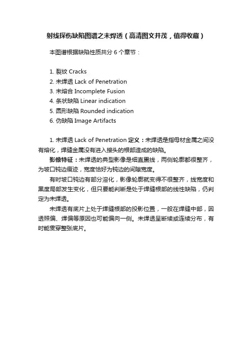
射线探伤缺陷图谱之未焊透(高清图文并茂,值得收藏)
本图谱根据缺陷性质共分6个章节:
1. 裂纹Cracks
2. 未焊透Lack of Penetration
3. 未熔合Incomplete Fusion
4. 条状缺陷Linear indication
5. 圆形缺陷Rounded indication
6. 伪缺陷Image Artifacts
1. 未焊透Lack of Penetration定义:未焊透是指母材金属之间没有熔化,焊缝金属没有进入接头的根部造成的缺陷。
影像特征:未焊透的典型影像是细直黒线,两侧轮廓都很整齐,为坡口钝边痕迹,宽度恰好为钝边的间隙宽度。
有时坡口钝边有部分溶化,影像轮廓就变得不很整齐,线宽度和黑度局部发生变化,但只要能判断是处于焊缝根部的线性缺陷,仍判定为未焊透。
未焊透有底片上处于焊缝根部的投影位置,一般在焊缝中部,因透照偏、焊偏等原因也可能偏向一侧。
未焊透呈断续或连续分布,有时能贯穿整张底片。
射线探伤RT射线探伤是一种基于所希望的辐射传递或吸收原理的无损探伤方法。
(工件中)厚度减薄或低密度的地方可以穿过较多的射线、因而吸收的辐射能量较小。
穿过被检工件的射线会在接收射线的底片上形成有对比度的影像。
具有高射线传递能力(低吸收)的区域会在经过暗室处理的底片上形成一个黑的影像区。
而具有较低射线传递能力(高吸收)的区域会在经过暗室处理的底片上形成一个较淡的影像区域。
图10.26说明了厚度对底片黑度的影响。
被检测物中最薄的地方在底片上形成的影象最黑,这是因为有较多的射线传递到了底片上。
被检测物中最厚的地方在底片上形成的影象最淡,这是因为有较多的射线被吸收而到达底片的射线相对较少。
图10.27说明了材料密度对底片黑度的影响。
在图10.27所示的金属材料中,铅的密度最高(11.34g/cc),接下来的密度次序是铜(8.96g/cc)、铁(7.87g/cc)、铝(2.70g/cc)。
.由于具有最高的密度(每单位体积上的重量),铅吸收最多的辐射,传送最少的辐射,所以产生最亮的底片。
低能量,无微粒的辐射是以γ射线或X射线的形式。
γ射线是由放射性的材料蜕变的结果;通常的放射源包括铱192,铯137和钴60。
这些放射源不断地发射出射线,当不用时,必须把它们放在称为γ照像机的屏蔽的贮存器中。
这些贮存器通常用铅和钢作屏蔽。
X射线是人造的;当电子高速运行时与物体相撞而产生X射线。
可以在一真空管中将电能转换成X辐射。
一低电流通过一白热的细丝,产生了电子。
而在细丝和目标金属之间的高电位(电压)加速了电子通过这个电压差区。
当电子流撞击到目标产生了X射线。
只有当把电压加入到X射线管时,辐射才会产生。
不管是用γ射线还是用X射线源,在试验中,试验物体并不是放射性的。
用此方法探到的表面下的缺陷是那些与被辐射的材料相比有不同密度的缺陷。
这包括中空,金属的和非金属的夹渣以及良好排列的未熔合和裂纹。
中空,如气孔,因为它们代表材料密度的巨大损失,所以在照片上产生暗区域。
焊缝射线照相底片的评判规律之南宫帮珍创作一、探伤人员要评片, 四项指标放在先*, 底片标识表记标帜齐又正, 铅字压缝为废片. 二、评片开始第一件, 先找四条熔合线, 小口径管照椭圆, 根部都在圈里面. 三、气孔形象最明显, 中心浓黑边缘浅, 夹渣属于非金属, 杂乱无章有棱边. 四、咬边成线亦成点, 似断似续常相见, 这个缺陷最好定, 位置就在熔合线.五、未焊透是年夜缺陷, 典范图象成直线, 间隙太小钝边厚, 投影部位靠中间. 六、内凹只在仰焊面, 间隙太年夜是关键, 内凹未透要分清, 内凹透度成弧线. 七、未熔合它斜又扁, 惯例透照难发现, 它的位置有规律, 都在坡口与层间. 八、横裂纵裂都危险, 横裂大都在概况, 纵裂分布范围广, 中间稍宽两端尖. 九、还有一种冷裂纹, 热影响区常发现, 冷裂具有延迟性, 焊完两天再拍片. 十、有了裂纹很危险, 斩草除根保平安, 裂纹不论长和短, 全部都是Ⅳ级片. 十一、未熔和也很危险, 黑度有深亦有浅, 一旦判定就是它, 亦是全部Ⅳ级片. 十二、危害缺陷未焊透, Ⅱ级焊缝不能有, 管线根据深和长, 容器跟着条渣走**. 十三、夹渣评定莫着忙, 分清圆形和条状, 长宽相比3为界, 年夜于3倍是条状. 十四、气孔危害其实不年夜, 标准对它很宽年夜, 长径折点套厚度, 中间厚度拔出法. 十五、多种缺陷年夜会合, 分门别类先评级, 2类相加减去Ⅰ, 3类相加减Ⅱ级. 十六、评片要想快又准, 下拜焊工领先生, 要问诀窍有哪些, 焊接工艺和投影.注:*四项指标系底片的黑度、灵敏度、清晰度、灰雾度必需符合标准的要求. **指单面焊的管线焊缝和双面焊的容器焊缝内未焊透的判定标准.Radiograph Interpretation - WeldsIn addition to producing high quality radiographs, the radiographer must also be skilled in radiographic interpretation. Interpretation of radiographs takes place in three basic steps which are (1) detection, (2) interpretation, and (3) evaluation. All of these steps make use of the radiographer's visual acuity. Visual acuity is the ability to resolve a spatial pattern in an image. The ability of an individual to detect discontinuities in radiography is also affected by the lighting condition in the place of viewing, and the experience level for recognizing various features in the image. The following material was developed to help students develop an understanding of the types of defects found in weldments and how they appear in a radiograph.DiscontinuitiesDiscontinuities are interruptions in the typicalstructure of a material. These interruptions may occur in the base metal, weld material or "heat affected" zones. Discontinuities, which do not meet the requirements ofthe codes or specification used to invoke and control an inspection, are referred to as defects.General Welding DiscontinuitiesThe following discontinuities are typical of all types of welding.Cold lap is a condition where the weld filler metal does not properly fuse with the base metal or the previousweld pass material (interpass cold lap). The arc does not melt the base metal sufficiently and causes the slightly molten puddle to flow into base material without bonding. Porosity气孔is the result of gas entrapment in the solidifying metal. Porosity can take many shapes on a radiograph but often appears as dark round or irregular spots or specks appearing singularly, in clusters or rows. Sometimes porosity is elongated and may have the appearance of having a tail This is the result of gasattempting to escape while the metal is still in a liquid state and is called wormhole porosity. All porosity is a void in the material it will have a radiographic density more than the surrounding area..Cluster porosity链状气孔is caused when flux coated electrodes are contaminated with moisture. The moisture turns into gases when heated and becomes trapped in the weld during the welding process. Cluster porosity appear just like regular porosity in the radiograph but the indications will be grouped close together.Slag inclusions夹渣 are nonmetallic solid material entrapped in weld metal or between weld and base metal. In a radiograph, dark, jagged asymmetrical shapes within the weld or along the weld joint areas are indicative of slag inclusions.Incomplete penetration (IP) or lack of penetration (LOP)未焊透occurs when the weld metal fails to penetrate the joint. It is one of the most objectionable weld discontinuities. Lack of penetration allows a natural stress riser from which a crack may propagate. The appearance on a radiograph is a dark area with well-defined, straight edges that follows the land or root face down the center of the weldment.Incomplete fusion未熔合is a condition where the weld filler metal does not properly fuse with the base metal. Appearance on radiograph: usually appears as a dark line or lines oriented in the direction of the weld seam along the weld preparation or joining area.Internal concavity or suck back内凹或吸入is condition where the weld metal has contracted as it cools and has been drawn up into the root of the weld. On a radiograph it looks similar to lack of penetration but the line has irregular edges and it is often quite wide in the center of the weld image.Internal or root undercut内部或根部咬边is an erosion of the base metal next to the root of the weld. In theradiographic image it appears as a dark irregular line offset from the centerline of the weldment. Undercutting is not as straight edged as LOP because it does notfollow a ground edge.External or crown undercut外部或顶部咬边is an erosion of the base metal next to the crown of the weld. In the radiograph, it appears as a dark irregular line along the outside edge of the weld area.Offset ormismatch错边are terms associated with a condition where two pieces being welded together are not properly aligned. The radiographic image is a noticeable difference in density between the two pieces. The difference in density is caused by the difference in material thickness. The dark, straight line is caused by failure of the weld metal to fuse with the land area. Inadequate weld reinforcement未填满is an area of a weld where the thickness of weld metal deposited is less than the thickness of the base material. It is very easy to determine by radiograph if the weld has inadequate reinforcement, because the image density in the area ofsuspected inadequacy will be more (darker) than the image density of the surrounding base material.Excess weld reinforcement增强余高is an area of a weld, which has weld metal added in excess of that specified by engineering drawings and codes. The appearance on a radiograph is a localized, lighter area in the weld. A visual inspection will easily determine if the weld reinforcement is in excess of that specified by the individual code involved in the inspection.Cracking裂纹can be detected in a radiograph only the crack is propagating in a direction that produced a change in thickness that is parallel to the x-ray beam. Cracks will appearas jagged and often very faintirregular lines. Cracks can sometimes appearing as "tails" on inclusions or porosity.Discontinuities in TIG weldsThe following discontinuities are peculiar to the TIG welding process. These discontinuities occur in most metals welded by the process including aluminum and stainless steels. The TIG method of welding produces aclean homogeneous weld which when radiographed is easily interpreted.Tungsten inclusions. 夹钨Tungsten is a brittle and inherently dense material used in the electrode in tungsten inert gas welding. If improper welding procedures are used, tungsten may be entrapped in the weld. Radiographically, tungsten is more dense than aluminum or steel; therefore, it shows as a lighter area with a distinct outline on the radiograph.Oxide inclusions夹氧化物are usually visible on the surface of material being welded (especially aluminum). Oxide inclusions are less dense than the surrounding materials and, therefore, appear as dark irregularly shaped discontinuities in the radiograph.Discontinuities in Gas Metal Arc Welds (GMAW)The following discontinuities are most commonly found in GMAW welds.Whiskers are short lengths of weld electrode wire, visible on the top or bottom surface of the weld orcontained within the weld. On a radiograph they appear as light, "wire like" indications.Burn through (icicles) results when too much heat causes excessive weld metal to penetrate the weld zone. Lumps of metal sag through the weld creating a thick globular condition on the back of the weld. On a radiograph, burn through appears as dark spots surrounded by light globular areas.welld-02 (Incomplete Root Fusion、根部未熔合)welld-03 (Insuffucient Reinforcement、增强高)welld-04 (Excess Root Penetration、根部焊瘤)welld-05 (External Undercut、外部咬肉)welld-06 (Internal Undercut、内部咬肉)welld-07 (Root Concavity、根部凹陷)welld-08 (Burn Through、烧穿)welld-09 (Isolated Slag Inclusion、单个的夹渣)welld-10 (Wagon Track - Slag Line、线状夹渣)welld-11 (Interrun Fusion、内部未熔合)welld-12 (Lack of Sidewall Fusion、内侧未熔合) welld-13 (Porosity、气孔)welld-14 (Cluster Porosity、链状气孔)welld-15 (Hollow Bead、夹珠)welld-16 (Transverse Crack、横向裂纹)welld-17 (Centerline Crack、中心线裂纹)welld-18 (Root Crack、根部裂纹)welld-19 (Tungsten Inclusion)夹钨。