机械类数控外文翻译外文文献英文文献数控.doc
- 格式:doc
- 大小:57.50 KB
- 文档页数:10
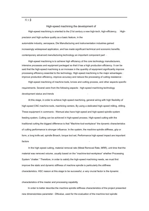
英文】High-speed machining the development ofHigh-speed machining is oriented to the 21st century a new high-tech, high-efficiency, High-precision and high surface quality as a basic feature, in theautomobile industry, aerospace, Die Manufacturing and instrumentation industries gained increasingly widespread application, and has made significant technical and economic benefits. contemporary advanced manufacturing technology an important component part 。
High-speed machining is to achieve high efficiency of the core technology manufacturers, intensive processes and equipment packaged so that it has a high production efficiency. It can be said that the high-speed machining is an increase in the quantity of equipment significantly improve processing efficiency essential to the technology. High-speed machining is the major advantages : improve production efficiency, improve accuracy and reduce the processing of cutting resistance。

外文资料及译文原文:Television Video SignalsAlthough over 50 years old , the standard television signal is still one of the most common way to transmit an image. Figure 8.3 shows how the television signal appears on an oscilloscope. This is called composite video, meaning that there are vertical and horizontal synchronization (sync) pulses mixed with the actual picture information.These pulses are used in the television receiver to synchronize the vertical and horizontal deflection circuits to match the video being displayed. Each second of standard video contains 30 complete images, commonly called frames , A video engineer would say that each frame contains 525 lines, the television jargon for what programmers call rows. This number is a little deceptive because only 480 to 486 of these lines contain video information; the remaining 39to 45 lines are reserved for sync pulses to keep the television’s circuits synchronized with the video signal.Standard television uses an interlaced format to reduce flicker in the displayed image. This means that all the odd lines of each frame are transmitted first, followed by the even lines. The group of odd lines is called the odd field, and the group of even lines is called the even field.Since each frame consists of two fields, the video signal transmits 60 fields per second. Each field starts with a complex series of vertical sync pulses lasting 1.3 milliseconds. This is followed by either the even or odd lines of video. Each line lasts for 63.5 microseconds, including a 10.2 microsecond horizontal sync pulse, separating one line from the next. Within each line, the analog voltage corresponds to the gray scale of the image, with brighter values being in the direction away from the sync pulses. This place the sync beyond the black range. In video jargon, the sync pulses are said to be blacker than black..The hardware used for analog-to-digital conversion of video signals is called a frame grabber. This is usually in the form of an electronics card that plugs into a computer, and connects to a camera through a coaxial cable. Upon command from software, the frame grabber waits for the beginning of the next frame, as indicated by the vertical sync pulses. During the following two fields,each line of video is sampled many times, typically 512,640 or 720 samples per line, at 8bits per sample. These samples are stored in memory as one row of the digital image.This way of acquiring a digital image results in an important difference between the vertical and horizontal directions. Each row in the digital image corresponds to one line in the video signal, and therefore to one row of wells in the CCD. Unfortunately, the columns are not so straightforward. In the CCD, each row contains between about 400 and800 wells (columns), depending on the particular device used. When a row of wells is read from the CCD, the resulting line of video is filtered into a smooth analog signal, such as in Figure 8.3. In other words, the video signal does not depend on how many columns are present in the CCD. The resolution in the horizontal direction is limited by how rapidly the analog signal is allowed to change. This is usually set at 3.2 MHz for color television, resulting in a rise time of about 100 nanoseconds, i.e, about 1/500th of the 53.2 microsecond video line.When the video signal is digitized in the frame grabber, it is converted back into columns, However, these columns in the digitized image have no relation to the columns in the CCD. The number of columns in the digital image depends solely on how many times the frame grabber samples each line of video. For example, a CCD might have 800 wells per row, while the digitized image might only have 512 pixels (i.e , columns) per row.The number of columns in the digitized image is also important for another reason. The standard television image has an aspect ratio of 4 to 3, i.e. , it is slightly wider than it is high. Motion pictures have the wider aspect ratio of 25 to 9. CCDs used for scientific applications often have an aspect ratio of 1 to 1, i.e , a perfect square. In any event, the aspect ratio of a CCD is fixed by the placement of the electrodes, and cannot be altered. However, the aspect ratio of the digitized image depends on thenumber of samples per line. This becomes a problem when the image is displayed, either on a video monitor or in a hardcopy. If the aspect ratio isn’t properly reproduced, the image looks squashed horizontally or vertically.The 525 line video signal described here is called NTSC (National Television Systems Committee), a standard defined way back in 1954. This is the system used in the United States and Japan. In Europe there are two similar standards called PAL (Phase Alternation by Line) and SECAM (Sequential Chrominance And Memory). The basic concepts are the same , just the numbers are different. Both PAL and SECAM operate with 25 interlaced frames per second, with 625 lines per frame. Just as with NTSC, some of these lines occur during the vertical sync, resulting in about 576 lines that carry picture information. Other more subtle differences relate to how color and sound are added to the signal.The most straightforward way of transmitting color television would be to have three separate analog signals, one for each of the three colors the human eye can detect: red, green and blue. Unfortunately, the historical development of television did not allow such a simple scheme. The color television signal was developed to allow existing black and white television sets to remain in use without modification. This was done by retaining the same signal for brightness information , but adding a separate signal for color information. In video jargon, the brightness iscalled the luminance signal, while the color is the chrominance signal. The chrominance signal is contained on a 3.58 MHz carrier wave added to the black and white video signal. Sound is added in this same way, on a 4.5 MHz carrier wave. The television receiver separates these three signals, processes them individually, and recombines them in the final diplay.译文:关键词:核心,合成信号,电压耦合电视信号尽管已经拥有50年的历史了,电视信号依然是常用的传递信息的途径之一。
机械类数控车床外文翻译外文文献英文文献数控原文来源:Zhao Chang-ming Liu Wang-ju (CNC Machining Process and equipment, 2002,China)一、摘要Equip the engineering level, level of determining the whole national economy of the modernized degree and modernized degree of industry, numerical control technology is it develop new developing new high-tech industry and most advanced industry to equip (such as information technology and his industry, biotechnology and his industry, aviation, spaceflight, etc. national defense industry) last technology and getting more basic most equipment. Numerical control technology is the technology controlled to mechanical movement and working course with digital information, integrated products of electromechanics that the numerical control equipment is the new technology represented by numerical control technology forms to the manufacture industry of the tradition and infiltration of the new developing manufacturing industry,Keywords:Numerical ControlTechnology, E quipment,industry二、译文数控技术和装备进展趋势及计策装备工业的技术水平和现代化程度决定着整个国民经济的水平和现代化程度,数控技术及装备是进展新兴高新技术产业和尖端工业〔如信息技术及其产业、生物技术及其产业、航空、航天等国防工业产业〕的使能技术和最差不多的装备。
数控技术外文文献翻译(含:英文原文及中文译文)英文原文The development trend of numerical control technology AbstractThe current trends in the development of numerical control technology and equipment in the world and the status quo of the development and industrialization of CNC equipment technology in China are briefly introduced. On this basis, we discuss the development of CNC technology and equipment in China under the new environment of China's accession to the WTO and further opening to the outside world. The importance of improving the level of China's manufacturing informatization and international competitiveness, and put forward some views on the development of China's CNC technology and equipment from both strategic and strategic aspects.The technological level and degree of modernization of the equipment industry determine the level of the entire national economy and the degree of modernization. Numerical control technology and equipment are the development of emerging high-tech industries and cutting-edge industries (such as information technology and its industries, biotechnology and its industries, aviation, aerospace, etc.) (Defense Industry Industry) enabling technology and basic equipment. Marx oncesaid that “the difference between various economic times is no t what is produced but how it is produced and what labor data it is used to produce”. Manufacturing technology and equipment are the most basic production materials for human production activities, and numerical control technology is the core technology of today's advanced manufacturing technologies and equipment. In the manufacturing industry of the world today, CNC technology is widely used to improve manufacturing capabilities and levels, and to improve the adaptability and competitiveness of dynamic markets. In addition, various industrialized countries in the world have also listed numerical control technology and numerical control equipment as strategic materials of the country. They not only take significant measures to develop their own numerical control technologies and their industries, but also have the key technology and equipment of “high-precision” numerical control. Our country adopts a policy of blockade and restriction. In short, the vigorous development of advanced manufacturing technologies centered on numerical control technology has become an important way for all developed countries in the world to accelerate economic development and improve their overall national strength and national status.Numerical control technology is a technology that uses digital information to control mechanical movement and work process. Numerical control equipment is a mechatronic product formed by thepenetration of new technologies represented by numerical control technology into traditional manufacturing industries and emerging manufacturing industries, namely, so-called digital equipment. Its technical scope covers many fields: (1) machinery manufacturing technology; (2) information processing, processing, and transmission technology; (3) automatic control technology; (4) servo drive technology;(5) sensor technology; (6) software Technology and so on. Keywords: CNC technology, machinery manufacturing, information processing, sensors1 Development Trends of Numerical Control TechnologyThe application of numerical control technology has not only brought about revolutionary changes in the traditional manufacturing industry, but also made manufacturing a symbol of industrialization. With the continuous development of numerical control technology and the expansion of application fields, he has made important contributions to the national economy and people's livelihood (IT, automotive The development of light industry, light industry, medical care, etc. is playing an increasingly important role, because the digitalization of the equipment required by these industries is a major trend of modern development. From the current trend of numerical control technology and its equipment development in the world, its main research hotspots are the following aspects [1~4].1.1 New trends in high-speed, high-precision processing technology and equipmentEfficiency and quality are the mainstays of advanced manufacturing technology. High-speed, high-precision machining technology can greatly improve efficiency, improve product quality and grade, shorten production cycle and increase market competitiveness. To this end, the Japanese Advanced Technology Research Institute will list it as one of the five major modern manufacturing technologies. The International Association of Production Engineers (CIRP) has identified it as one of the central research directions for the 21st century.In the passenger car industry, the production cycle of 300,000 vehicles per year is 40 seconds per vehicle, and multi-species processing is one of the key issues that must be addressed for car equipment. In the aviation and aerospace industries, the parts processed by them are mostly thin-walled. With thin ribs, the rigidity is poor, and the material is aluminum or aluminum alloy. These ribs and walls can be processed only when the high cutting speed and cutting force are small. Recently, the method of “hollowing out” large-size aluminum alloy billets has been used to manufacture large parts such as wings and fuselage to replace multiple parts and assembled by numerous rivets, screws, and other coupling methods to obtain strength, stiffness, and reliability of components. improve. All of these require high-speed, high-precision andhigh-flexibility for processing equipment.From the standpoint of EMO2001, the feed rate of high-speed machining centers can reach 80m/min, or even higher, and the airspeed can reach around 100m/min. At present, many automobile plants in the world, including China's Shanghai General Motors Corporation, have adopted a part of the production line consisting of a high-speed machining center to replace the combined machine tools. The HyperMach machine tool feed rate of CINCINNATI, USA is up to 60m/min, the speed is 100m/min, the acceleration is 2g, and the spindle speed has reached 60,000r/min. It takes only 30 minutes to machine a thin-walled aircraft part, and the same part takes 3h for general high-speed milling and 8h for normal milling; the spindle speed and acceleration of the twin-spindle lathe of DMG, Germany, reach 12*!000r/mm respectively. And 1g.In terms of machining accuracy, in the past 10 years, the machining accuracy of ordinary CNC machine tools has increased from 10μm to 5μm, precision machining centers have increased from 3~5μm to 1~1.5μm, and ultra-precision machining precision has begun to enter the nanometer level. (0.01μm).In terms of reliability, the MTBF value of foreign numerical control devices has reached more than 6000 hours, and the MTBF value of the servo system has reached more than 30,000 hours, showing very highreliability.In order to achieve high-speed, high-precision machining, the supporting functional components such as electric spindles and linear motors have been rapidly developed and the application fields have been further expanded.1.2 Rapid development of 5-axis simultaneous machining and compound machiningThe use of 5-axis simultaneous machining of 3D surface parts allows cutting with the best geometry of the tool, resulting in not only a high degree of finish, but also a significant increase in efficiency. It is generally considered that the efficiency of a 5-axis machine tool can be equal to 2 3-axis linkage machines. Especially when using ultra-hard material milling tools such as cubic boron nitride for high-speed milling of hardened steel parts, 5-axis simultaneous machining can be compared with 3-axis linkage. Processing to play a higher efficiency. In the past, due to the complexity of the 5-axis linkage CNC system and the host machine structure, the price was several times higher than that of the 3-axis linkage CNC machine tool, and the programming technology was more difficult, which restricted the development of 5-axis linkage machine tools.At present, due to the emergence of electric spindles, the structure of the composite spindle head that realizes 5-axis simultaneous machining isgreatly simplified, its manufacturing difficulty and cost are greatly reduced, and the price gap of the numerical control system is reduced. As a result, the development of composite spindle head type 5-axis linkage machine tools and compound machine tools (including 5-sided machine tools) has been promoted.At the EMO2001 exhibition, the new 5-axis machine tool of Nippon Machine Tool Co., Ltd. adopts a compound spindle head, which can realize the processing of four vertical planes and processing at any angle, so that 5-sided machining and 5-axis machining can be realized on the same machine tool. It can realize the processing of inclined surface and inverted cone. Germany DMG company exhibited DMUV oution series machining center, which can be processed in five-face machining and five-axis linkage in a single clamping. It can be directly or indirectly controlled by CNC system control or CAD/CAM.1.3 Intelligentization, openness, and networking have become major trends in the development of modern digital control systemsThe 21st century CNC equipment will be a certain intelligent system. The intelligent content is included in all aspects of the CNC system: in order to pursue the processing efficiency and processing quality in the intelligent, such as the process of adaptive control, process parameters automatically Generated; To improve the driving performance and the use of convenient connection intelligent, such as feed-forward control,adaptive calculation of motor parameters, automatic identification load automatic selection model, self-tuning, etc.; simplify the programming, simplify the operation of intelligent, such as smart The automatic programming, intelligent man-machine interface, etc.; as well as the contents of intelligent diagnosis, intelligent monitoring, convenient system diagnosis and maintenance.In order to solve the problems of traditional CNC system closure and industrial application of CNC application software. At present, many countries have conducted research on open numerical control systems such as NGC of the United States, OSACA of the European Community, OSEC of Japan, and ONC of China. The openness of numerical control systems has become the future of CNC systems. The so-called open CNC system is the development of CNC system can be in a unified operating platform, for machine tool manufacturers and end users, by changing, adding or cutting structure objects (CNC function), to form a series, and can be convenient to the user's special The application and technology are integrated into the control system to quickly realize open numerical control systems of different varieties and different grades to form brand-name products with distinctive personality. At present, the architecture specification, communication specification, configuration specification, operation platform, numerical control system function library and numerical control system function software development toolof open CNC system are the core of current research.Networked CNC equipment is a new bright spot in the international well-known machine tool exposition in the past two years. The networking of CNC equipment will greatly satisfy the requirements of information integration for production lines, manufacturing systems, and manufacturing companies. It is also the basic unit for realizing new manufacturing models such as agile manufacturing, virtual enterprise, and global manufacturing. Some famous domestic and foreign CNC machine tools and numerical control system manufacturing companies have introduced relevant new concepts and prototypes in the past two years. For example, at the EMO 2001 exhibition, the “Cyber Production Center” exhibited by Japan's Mazak company Mazak Production Control Center (CPC); Okuma Machine Too l Company, Japan exhibited “ITplaza” (Information Technology Plaza, IT Plaza); Open Manufacturing Environment (Open Manufacturing Environment, OME), exhibited by Siemens, Germany Etc., reflecting the trend of the development of CNC machine tools to the direction of the network.1.4 Emphasizing the Establishment of New Technology Standards and Specifications1.4.1 About Design and Development of CNC SystemsAs mentioned above, the open CNC system has better versatility, flexibility, adaptability, and expandability. The United States, theEuropean Community, and Japan have implemented strategic development plans one after another, and have conducted the open architecture system specification (OMAC). , OSACA, OSEC) research and development, the world's three largest economies in the short term carried out almost the same set of scientific plans and norms, indicating that the arrival of a new revolution in digital technology. In 2000, China began to conduct research and development of the regulatory framework for China's ONC numerical control system.1.4.2 About CNC StandardsCNC standards are a trend in the development of manufacturing informatization. The information exchange in the 50 years since the birth of CNC technology was based on the ISO 6983 standard. That is how the G and M codes describe how to process. The essential feature is the processing-oriented process. Obviously, he has been unable to meet the high speed of modern CNC technology. The need for development. For this purpose, a new CNC system standard ISO14649 (STEP-NC) is being researched and developed internationally. Its purpose is to provide a uniform data model that can describe the entire life cycle of a product without relying on a neutral mechanism of a specific system. , in order to achieve the entire manufacturing process, and even the standardization of product information in various industrial fields. The emergence of STEP-NC may be a revolution in CNC technology. It will have aprofound impact on the development of CNC technology and even the entire manufacturing industry. First, STEP-NC proposes a brand-new manufacturing concept. In the traditional manufacturing concept, NC machining programs are concentrated on a single computer. Under the new standard, NC programs can be distributed on the Internet. This is the direction of open and networked CNC technology. Secondly, STEP-NC CNC system can also greatly reduce the processing drawings (about 75%), processing program preparation time (about 35%) and processing time (about 50%).At present, European and American countries attach great importance to the research of STEP-NC, and Europe has initiated STEP-NC's IMS plan ( Participation in this program comes from 20 CAD/CAM/CAPP/CNC users, vendors and academic institutions in Europe and Japan. STEPTools of the United States is the developer of global manufacturing data exchange software. He has developed a SuperModel for the information exchange of CNC machine tools. Its goal is to describe all machining processes with a unified specification. This new data exchange format has now been validated on prototype prototypes equipped with SIEMENS, FIDIA and European OSACA-NC numerical control systems.2 Basic Estimates of China's CNC Technology and Its Industrial DevelopmentCNC technology in China started in 1958. The development process in the past 50 years can be roughly divided into three stages: the first stage from 1958 to 1979, which is the closed development stage. At this stage, the development of numerical control technology is relatively slow due to the limitations of foreign technology and China's basic conditions. The second stage is the introduction of technology during the “sixth and fifth” periods of the country, the “seventh five-year plan” period, and the “eighth five-year plan period,”and it will be digested and absorbed to initially establish the stage of the national production system. At this stage, due to the reform and opening up and the country’s attention, as well as the improvement of the research and development environment an d the international environment, China’s CNC technology has made great progress in research, development, and localization of products. The third stage is the implementation of industrialization research in the later period of the "Eighth Five-Year Plan" and the "Ninth Five-Year Plan" period of the country, entering the stage of market competition. At this stage, the industrialization of domestically-manufactured CNC equipment has achieved its essenceSexual progress. At the end of the “Ninth Five-Year Plan” period, the domestic market share of domestic CNC machine tools reached 50%, and the number of domestically-manufactured numerical control systems (pervasive models) also reached 10%.Looking at the development process of CNC technology in China in the past 50 years, especially after four five-year plans, the overall results are as follows:a. It lays the foundation for the development of CNC technology and basically masters modern CNC technology. China has now basically mastered the basic technologies from numerical control systems, servo drives, numerical control mainframes, special planes and their accessories. Most of these technologies already have the basis for commercial development. Some technologies have been commercialized and industrialized.b. Initially formed a CNC industrial base. Based on the research results and the commercialization of some technologies, we have established numerical control system production plants such as Huazhong Numerical Control and Aerospace Numerical Control which have mass production capabilities. Lanzhou Electric Machinery Factory, Huazhong Numerical Control and a number of servo systems and servo motor manufacturers, as well as a number of CNC machine manufacturers such as Beijing No. 1 Machine Tool Plant and Jinan No. 1 Machine Tool Plant. These production plants have basically formed China's CNC industrial base.c. Established a basic team of CNC research, development and management talents.Although significant progress has been made in the research, development, and industrialization of numerical control technology, we must also soberly realize that the research and development of high-end numerical control technologies in China, especially the status quo of the technological level of industrialization and the actual needs of China There is a big gap. Although our country's development speed is very fast in the vertical direction, the horizontal ratio (compared with foreign countries) not only has a gap in the level of technology, but also has a gap in the development speed in certain aspects, that is, the gap in the technological level of some highly sophisticated numerical control equipment has expanded. From the international point of view, the estimated level of China's numerical control technology and industrialization is roughly as follows:a. On the technical level, it will be about 10 to 15 years behind the advanced level in foreign countries, and it will be even bigger in terms of sophisticated technology.b. At the industrialization level, the market share is low, the variety coverage is small, and scale production has not yet been established; the specialized production level of functional components and the complete set capacity are low; the appearance quality is relatively poor; the reliability is not high, and the degree of commercialization is insufficient; The domestic CNC system has not established its own brand effect, andthe user's confidence is insufficient.c. On the ability of sustainable development, the research and development and engineering capabilities of pre-competitive numerical control technology are weak; the application of numerical control technology is not strong; the research and formulation of related standard specifications is lagging behind.The main reasons for analyzing the above gaps are as follows:a. Awareness. Insufficient understanding of the arduous, complex and long-term characteristics of the domestic CNC industry process; Insufficient estimates of market irregularities, foreign blockades, killings, and systems; and insufficient analysis of the application level and capabilities of CNC technology in China.b. Systematic aspects. From the point of view of technology, attention has been paid to the issue of CNC industrialization. It has been a time to consider the issue of CNC industrialization from the perspectives of system and industry chain; there is no complete supporting system of high-quality supporting systems, perfect training, and service networks. .c. Mechanisms. Bad mechanisms have led to brain drain, which in turn has restricted technological and technological route innovations and product innovations, and has constrained the effective implementation of planning. It is often planned to be ideal and difficult to implement.d. Technical aspects. Enterprises have little ability to independentlyinnovate in technology, and the engineering ability of core technologies is not strong. The standard of machine tools is backward, the level is low, and the new standard of CNC system is not enough.3 Strategic Thinking on the Development of CNC Technology and Industrialization in China3.1 Strategic ConsiderationsChina is a manufacturing country, and we must try to accept the transfer of the front-end rather than the back-end in the industrial transfer of the world. That is to master the advanced manufacturing core technologies, otherwise, in the new round of international industrial restructuring, China's manufacturing industry will further “empty core”. At the expense of resources, the environment, and the market, we may obtain only the international "processing centers" and "assembly centers" in the world's new economic structure, rather than the status of manufacturing centers that master core technologies. This will seriously affect our country. The development of modern manufacturing.We should pay attention to numerical control technology and industrial issues from the perspective of national security strategy. First of all, we must look at social security because manufacturing industry is the industry with the largest number of employed people in China. Manufacturing industry development can not only improve the people’s living standards, but also ease the country’s The pressure of employmentguarantees social stability. Secondly, from the perspective of national defense security, Western developed countries classify high-precision numerical control products as national strategic materials and implement embargoes and restrictions on China. The “Toshiba Incident” and the “Cox Report” "This is the best illustration.3.2 Development StrategyFrom the perspective of China’s basic national conditions, taking the country’s strategic needs and the market demand of the national economy as the guide, and aiming at improving the comprehensive competitiveness and industrialization le vel of China’s manufacturing equipment industry, we can use systematic methods to choose to dominate the early 21st century in China. The key technologies for the development and upgrade of the manufacturing equipment industry and supporting technologies and supporting technologies for supporting industrialization development are the contents of research and development and the leap-forward development of the manufacturing equipment industry. Emphasizing the market demand as the orientation, that is, taking CNC terminal products as the mainstay, and driving the CNC industry with complete machines (such as large-scale CNC lathes, milling machines, high-speed, high-precision and high-performance CNC machine tools, typical digital machines, key equipment of key industries, etc.). development of. The focus is on the reliability and production scale of CNC systems andrelated functional components (digital servos and motors, high-speed spindle systems and accessories for new equipment, etc.). Without scale, there will be no high-reliability products; without scale, there will be no cheap and competitive products; of course, CNC equipment without scale in China will be difficult to come to the fore. In the research and development of high-precision equipment, we must emphasize the close integration of production, learning, research, and end-users, and aim at “doing, using, and selling off” as a goal, and implement national research on the will of the country to solve the urgent need of the country. . Before the competition, CNC technology emphasizes innovation, emphasizes research and development of technologies and products with independent intellectual property rights, and lays a foundation for the sustainable development of China's CNC industry, equipment manufacturing industry, and even the entire manufacturing industry.中文译文数控技术的发展趋势摘要本文简要介绍了当今世界数控技术及装备发展的趋势及我国数控装备技术发展和产业化的现状, 在此基础上讨论了在我国加入WTO 和对外开放进一步深化的新环境下, 发展我国数控技术及装备、提高我国制造业信息化水平和国际竞争能力的重要性, 并从战略和策略两个层面提出了发展我国数控技术及装备的几点看法。
数控车床主轴部件机械外文文献翻译、中英文翻译、外文翻译数控车床主轴部件车床是一种主要用于加工旋转表面和平整边缘的机床。
根据使用目的、结构、刀具数量和自动化程度的不同,车床可以分为普通车床、万能车床、转塔车床、立式车床、自动车床和特殊车床。
虽然车床种类繁多,但它们在结构和操作原理上具有共同特性。
普通车床是最常用的代表类型,下面将介绍普通车床的主要部分。
车床床身是车床的主骨架,由两个垂直支柱上的水平横梁组成。
为减振,它通常由灰铸铁或球墨铸铁铸造而成。
车床床身上有导轨,可以让大拖板轻松纵向滑动。
车床床身的高度应适当以方便技师工作。
主轴箱固定在车床床身的左侧,包括轴线平行于导轨的主轴。
主轴通过齿轮箱驱动,齿轮箱可以提供多种不同的速度(通常是6到18速)。
现代车床有些采用无级调速主轴箱,采用摩擦、电力或液压驱动。
主轴往往是中空的,纵向有一通孔,可以通过此孔进给棒料。
同时,此孔为锥形表面,可以安装普通车床顶尖。
主轴外表面是螺纹,可以安装卡盘、花盘或类似的装置。
尾架总成包括底座、尾架体和套筒轴。
底座是能在车床床身上沿导轨滑动的铸件,有定位装置,可以让整个尾架根据工件长度锁定在任何需要位置。
使用手轮和螺杆,与螺杆啮合的是一固接在套筒轴上的螺母。
套筒轴开口端的孔是锥形的,能安装车床顶尖或诸如麻花钻和镗杆之类的工具。
套筒轴通过定位装置能沿着它的移动路径被锁定在任何点。
大拖板的主要功能是安装刀具和产生纵向和/或横向进给。
它实际上是一由车床床身V形导轨引导的、能在车床床身主轴箱和尾架之间滑动的H形滑块。
大拖板可以手动或通过溜板箱和光杆(进给杆)或丝杆(引导螺杆)机动。
本文介绍了在传统普通车床上进行的各种机加工作业。
但是,需要注意的是现代计算机数控车床具有更多的功能,并且可以进行其他操作,例如仿型。
圆柱面车削是所有车床操作中最简单也是最常见的。
工件旋转一整圈产生一个圆心落在车床主轴上的圆;由于刀具的轴向进给运动,这种动作重复许多次。
(数控加工)机械类数控外文翻译外文文献英文文献数控NumericalControlOneofthemostfundamentalconceptsintheareaofadvancedmanufacturingte chnologiesisnumericalcontrol(NC).PriortotheadventofNC,allmachinetools weremanualoperatedandcontrolled.Amongthemanylimitationsassociatedwith manualcontrolmachinetools,perhapsnoneismoreprominentthanthelimitation ofoperatorskills.Withmanualcontrol,thequalityoftheproductisdirectlyre latedtoandlimitedtotheskillsoftheoperator.Numericalcontrolrepresentst hefirstmajorstepawayfromhumancontrolofmachinetools.Numericalcontrolmeansthecontrolofmachinetoolsandothermanufacturin gsystemsthoughtheuseofprerecorded,writtensymbolicinstructions.Rathert hanoperatingamachinetool,anNCtechnicianwritesaprogramthatissuesoperat ionalinstructionstothemachinetool,Foramachinetooltobenumericallycontr olled,itmustbeinterfacedwithadeviceforacceptinganddecodingthep2ogramm edinstructions,knownasareader.Numericalcontrolwasdevelopedtoovercomethelimitationofhumanoperato r,andithasdoneso.Numericalcontrolmachinesaremoreaccuratethanmanuallyo peratedmachines,theycanproducepartsmoreuniformly,theyarefaster,andthe long-runtoolingcostsarelower.ThedevelopmentofNCledtothedevelopmentofs everalotherinnovationsinmanufacturingtechnology:1.Electricaldischargemachining.sercutting.3.Electronbeamwelding.Numericalcontrolhasalsomademachinetoolsmoreversatilethantheirmanuallyoperatedpredecessors.AnNCmachinetoolcanautomaticallyproduceawidev arietyofpar4s,eachinvolvinganassortmentofundertaketheproductionofprod uctsthatwouldnothavebeenfeasiblefromaneconomicperspectiveusingmanuall ycontrolledmachinetoolsandprocesses.Likesomanyadvancedtechnologies,NCwasborninthelaboratoriesoftheMas sachusettsInstituteofTechnology.TheconceptofNCwasdevelopedintheearly1 950swithfundingprovidedbytheU.SAirForce.Initsearlieststages,NCmachine swereabletomakestraightcutsefficientlyandeffectively.However,curvedpathswereaproblembecausethemachinetoolhadtobeprogra mmedtoundertakeaseriesofhorizontalandverticalstepstoproduceacurve.The shorteristhestraightlinesmakingupthestep,thesmootheris4hecurve.Eachli nesegmentinthestepshadtobecalculated.Thisproblemledtothedevelopmentin1959oftheAutomaticallyProgrammedT ools(APT)languageforNCthatusesstatementssimilartoEnglishlanguagetodef inethepartgeometry,describethecuttingtoolconfiguration,andspecifythen ecessarymotions.ThedevelopmentoftheAPTlanguagewasamajorstepforwardint hefurtherdevelopmentofNCtechnology.TheoriginalNCsystemwerevastlydiffe rentfromthoseusedpunchedpaper,whichwaslatertoreplacedbymagneticplasti ctape.Atapereaderwasusedtointerprettheinstructionswrittenonthetapefor themachine.Together,all/fthisrepresentedgiantstepforwardinthecontrolo fmachinetools.However,therewereanumberofproblemswithNCatthispointinit sdevelopment.Amajorproblemwasthefragilityofthepunchedpapertapemedium.Itwascomm onforthepapercontainingtheprogrammedinstructionstobreakortearduringam achiningprocess,Thisproblemwasexacerbatedbythefactthateachsuccessivet imeapartwasproducedonamachinetool,thepapertapecarryingtheprogrammedin structionshadtorerunthoughtthereader.Ifitwasnecessarytoproduce100copi esofagivenpart,itwasalsonecessarytorunthepapertapethoughtthereader100 separatetimes.Fragilepapertapessimplycouldnotwithstandtherigorsofshop floorenvironmentandthiskindofrepeateduse.Thisledtothedevelopmentofaspecialmagnetictape.Whereasthepapertape carriedtheprogrammedinstructionsasaseriesofholespunchedinthetape,theT hismostimportantofthesewasthatitwasdifficultorimpossibletochangethein structionsenteredonthetape.Tomakeeventhemostminoradjustmentsinaprogra mofinstructions,itwasnecessarytointerruptmachiningoperationsandmakean ewtape.Itwasalsostillnecessarytorunthetapethoughtthereaderasmanytimes astherewerepartstobeproduced.Fortunately,computertechnologybecomearea lityandsoonsolvedtheproblemsofNC,associatedwithpunchedpaperandplastic tape.Thedevelopmentofaconceptknownasnumericalcontrol(DNC)solvethepaper andplastictapeproblemsassociatedwithnumericalcontrolbysimplyeliminati ngtapeasthemediumforcarryingtheprogrammedinstructions.Indirectnumeric alcontrol,machinetoolsaretied,viaadatatransmissionlink,toahostcompute randfedtothemachinetoolasneededviathedatatransmissionlinkage.Directnumericalcontrolrepresentedamajorstepforwardoverpunchedtapeandplasticta pe.However,itissubjecttothesamelimitationasalltechnologiesthatdependo nahostcomputer.Whenthehostcomputergoesdown,themachinetoolsalsoexperie ncedowntime.Thisproblemledtothedevelopmentofcomputernumericalcontrol.Thedevelopmentofthemicroprocessorallowedforthedevelopmentofprogra mmablelogiccontrollers(PLC)andmicrocomputers.Thesetwotechnologiesallo wedforthedevelopmentofcomputernumericalcontrol(CNC).WithCNC,eachmachi netoolhasaPLCoramicrocomputerthatservesthesamepurpose.Thisallowsprogr Csolvedtheproblems associateddowntimeofthehostcomputer,butitintroducedanotherproblemknow nasdatamanagement.Thesameprogrammightbeloadedontendifferentmicrocompu terswithnocommunicationamongthem.Thisproblemisintheprocessofbeingsolv edbylocalareanetworksthatconnectDigitalSignalProcessorsTherearenumeroussituationswhereanalogsignalstobeprocessedinmanywa ys,likefilteringandspectralanalysis,Designinganaloghardwaretoperformt hesefunctionsispossiblebuthasbecomelessandpractical,duetoincreasedper formancerequirements,flexibilityneeds,andtheneedtocutdownondevelopmen t/testingtime.Itisinotherwordsdifficultpmdesignanaloghardwareanalysis ofsignals.Theactofsamplingansignalintothehatarespecialisedforembeddedsignal processingoperations,andsuchaprocessoriscalledaDSP,whichstandsforDigi talSignalProcessor.TodaytherearehundredsofDSPfamiliesfromasmanymanufacturers,eachonedesignedforaparticularprice/performance/usagegroup.Man yofthelargestmanufacturers,likeTexasInstrumentsandMotorola,offerboths pecialisedDSP’sforcertainfieldslikemotor-controlormodems,andgeneralh igh-performanceDSP’sthatcanperformbroadrangesofprocessingtasks.Devel opmentkitsan`softwarearealsoavailable,andtherearecompaniesmakingsoftw aredevelopmenttoolsforDSP’sthatallowstheprogrammertoimplementcomplex processingalgorithmsusingsimple“drag‘n’drop”methodologies.DSP’smoreorlessfallintotwocategoriesdependingontheunderlyingarch itecture-fixed-pointandfloating-point.Thefixed-pointdevicesgenerallyo perateon16-bitwords,whilethefloating-pointdevicesoperateon32-40bitsfl oating-pointwords.Needlesstosay,thefixed-pointdevicesaregenerallychea per.Anotherimportantarchitecturaldifferenceisthatfixed-pointprocessor stendtohaveanaccumulatorarchitecture,withonlyone“generalpurpose”reg ister,makingthemquitetrickytoprogramandmoreimportantly,makingC-compil ersinherentlyinefficient.Floating-pointDSP’sbehavemorelikecommongene ral-purposeCPU’s,withregister-files.TherearethousandsofdifferentDSP’sonthemarket,anditisdifficulttas kfindingthemostsuitableDSPforaproject.Thebestwayisprobablytosetupacon straintandwishlist,andtrytocomparetheprocessorsfromthebiggestmanufact urersagainstit.The“bigfour”manufacturersofDSPs:TexasInstruments,Motorola,AT&Ta ndAnalogDevices.Digital-to-analogconversionInthecaseofMPEG-Audiodecoding,digitalcompresseddataisfedintotheDS Pwhichperformsthedecoding,thenthedecodedsampleshavetobeconvertedbacki ntotheanalogdomain,andtheresultingsignalfedanamplifierorsimilaraudioe quipment.Thisdigitaltoanalogconversion(DCA)isperformedbyacircuitwitht hesamename&DifferentDCA’sprovidedifferentperformanceandquality,asmea suredbyTHD(Totalharmonicdistortion),numberofbits,linearity,speed,filt ercharacteristicsandotherthings.TheTMS320familyDQPofTexasInstrumentsTheTLS320familyconsistsoffixed-point,floating-point,multiprocesso rdigitalsignalprocessors(D[Ps),andfoxed-pointDSPcontrollers.TMS320DSP haveanarchitecturedesignedspecificallyforreal-timesignalprocessing.Th e’F/C240isanumberofthe’C2000DSPplatform,andisoptimizedforcontrolapp lications.The’C24xseriesofDSPcontrollerscombinesthisreal-timeprocess ingcapabilitywithcontrollerperipheralstocreateanidealsolutionforcontr olsystemapplications.ThefollowingcharacteristicsmaketheTMS320familyth erightchoiceforawiderangeofprocessingapplications:---Veryflexibleinstructionset---Inherentoperationalflexibility---High-speedperformance---Innovativeparallelarchitecture---CosteffectivenessDeviceswithinagenerationoftheTMS320familyhavethesameCPUstructure butdifferenton-chipmemoryandperipheralconfigurations.Spin-offdevicesu senewcombinationsofOn-chipmemoryandperipheralstosatisfyawiderangeofne edsintheworldwideelectronicsmarket.Byintegratingmemoryandperipheralso ntoasinglechip,TMS320devicesreducesystemcostsandsavecircuitboardspace .The16-bit,fixed-pointDSPcoreofthe‘C24xdevicesprovidesanalogdesi gnersadigitalsolutionthatdoesnotsacrificetheprecisionandperformanceof theirsystemperformancecanbeenhancedthroughtheuseofadvancedcontrolalgo rithmsfortechniquessuchasadaptivecontrol,Kalmanfiltering,andstatecont rol.The‘C24xDSPcontrollerofferreliabilityandprogrammability.Analogco ntrolsystems,ontheotherhand,arehardwiredsolutionsandcanexperienceperf ormancedegradationduetoaging,componenttolerance,anddrift.Thehigh-speedcentralprocessingunit(CPU)allowsthedigitaldesignert oprocessalgorithmsinrealtimeratherthanapproximateresultswithlook-upta bles.TheinstructionsetoftheseDSPcontrollers,whichincorporatesbothsign alprocessinginstructionsandgeneral-purposecontrolfunctions,coupledwit htheextensivedevelopmenttimeandprovidesthesameeaseofuseastraditional8 -and16-bitmicrocontrollers.Theinstructionsetalsoallowsyoutoretainyour softwareinvestmentwhenmovingfromothergeneral-purpose‘C2xxgeneration, sourcecodecompatiblewiththe’C2xgeneration,andupwardlysourcecodecompa tiblewiththe‘C5xgenerationofDSPsfromTexasInstruments.The‘C24xarchitectureisalsowell-suitedforprocessingcontrolsignal s.Itusesa16-bitwordlengthalongwith32-bitregistersforstoringintermedia teresults,andhastwohardwareshiftersavailabletoscalenumbersindependent lyoftheCPU.Thiscombinationminimizesquantizationandtruncationerrors,an dincreasesp2ocessingpowerforadditionalfunctions.Suchfunctionsmightinc ludeanotchfilterthatcouldcancelmechanicalresonancesinasystemoranestim ationtechniquethatcouldeliminatestatesensorsinasystem.The‘C24xDSPcontrollerstakeadvantageofansetofperipheralfunctions thatallowTexasInstrumentstoquicklyconfigurevariousseriesmembersfordif ferentprice/performancepointsorforapplicationoptimization.Thislibraryofbothdigitalandmixed-signalperipheralsincludes:---Timers---Serialcommunicationsports(SCI,SPI)---Analog-to-digitalconverters(ADC)---Eventmanager---Systemprotection,suchaslow-voltageandwatchdogtimerTheDSPcontrollerperipherallibraryiscontinuallygrowingandchanging tosuittheoftomorrow’sembeddedcontrolmarketplace.TheTMS320F/C240isthefirststandarddeviceintroducedinthe‘24xserie sofDSPcontrollers.Itsetsthestandardforasingle-chipdigitalmotorcontrol ler.The‘240canexecute20MIPS.Almostallinstructionsareexecutedinasimpl ecycleof50ns.Thishighperformanceallowsreal-timeexecutionofverycomple8controlalgorithms,suchasadaptivecontrolandKalmanfilters.Veryhighsampl ingratescanalsobeusedtominimizeloopdelays.The‘240hasthearchitecturalfeaturesnecessaryforhigh-speedsignalp rocessinganddigitalcontrolfunctions,andithastheperipheralsneededtopro videasingle-chipsolutionformotorcontrolapplications.The‘240ismanufac turedusingsubmicronCMOStechnology,achievingalogpowerdissipationrating.A lsoincludedareseveralpower-downmodesforfurtherpowersavings.Someapplic ationsthatbenefitfromtheadvancedprocessingpowerofthe‘240include: ---Industrialmotordrives---Powerinvertersandcontrollers---Automotivesystems,suchaselectronicpowersteering,antilockbrake s,andclimatecontrol---ApplianceandHVACblower/compressormotorcontrols---Printers,copiers,andotherofficeproducts---Tapedrives,magneticopticaldrives,andothermassstorageproducts---RoboticandCNCmillingmachinesTofunctionasasystemmanager,aDSPmusthaverobuston-chipI/Oandotherp eripherals.Theeventmanagerofthe‘240isunlikeanyotheravailableonaDSP.T hisapplication-optimizedperipheralunit,coupledwiththehighperformanceD SPcore,enablestheuseofadvancedcontroltechniquesforhigh-precisionandhi gh-efficiencyfullvariable-speedcontrolofallmotortypes.Includeintheeve ntmanagerarespecialpulse-widthmodulation(PWM)generationfunctions,suchasaprogrammabledead-bandfunctionandaspacevectorPWMstatemachinefor3-ph asemotorsthatprovidesstate-of-the-artmaximumefficiencyintheswitchingo fpowertransistors.Thereindependentupdowntimers,eachwithit’sowncompareregister,sup portthegenerationofasymmetric(noncentered)aswellassymmetric(centered) PWMwaveforms.Open-LoopandClosed-LoopControlOpen-loopControlSystemsThewordautomaticimpliesthatthereisacertainamountofsophistication inthecontrolsystem.Byautomatic,itgenerallymeansThatthesystemisusually capableofadaptingtoavarietyofoperatingconditionsandisabletorespondtoa classofinputssatisfactorily.However,notanytypeofcontrolsystemhastheau ually,theautomaticfeatureisachievedbyfeed.gthefeedbackstructure,itiscalledanopen-loopsystem,whichisthesimp lestandmosteconomicaltypeofcontrolsystem.inaccuracyliesinthefactthato nemaynotknowtheexactcharacteristicsofthefurther,whichhasadefinitebear ingontheindoortemperature.Thisalcopointstoanimportantdisadvantageofth eperformanceofanopen-loopcontrolsystem,inthatthesystemisnotcapableofa daptingtovariationsinenvironmentalconitionsortoexternaldisturbances.I nthecaseofthefurnacecontrol,perhapsanexperiencedpersoncanprovidecontr olforacertaindesiredtemperatureinthehouse;butidthedoorsorwindowsareop enedorclosedintermittentlyduringtheoperatingperiod,thefinaltemperatureinsidethehousewillnotbeaccuratelyregulatedbytheopen-loopcontrol.Anelectricwashingmachineisanothertypicalexampleofanopen-loopsyst em,becausetheamountofwashtimeisentirelydeterminedbythejudgmentandesti mationofthehumanoperator.Atrueautomaticelectricwashingmachineshouldha vethemeansofcheckingthecleanlinessoftheclothescontinuouslyandturnitse dtoffwhenthedesireddegisedofcleanlinessisreached.Closed-LoopControlSystemsWhatismissingintheopen-loopcontrolsystemformoreaccurateandmoread aptablecontrolisalinkorfeedbackfromtheoutputtotheinputofthesystem.Ino rdertoobtainmoreaccuratebontrol,thecontrolledsignalc(t)mustbefedbacka ndcomparedwiththereferenceinput,andanactuatingsignalproportionaltothe differenceoftheoutputandtheinputmustbesentthroughthesystemtocorrectth eerror.Asystemwithoneormorefeedbackpat(slikethatjustdescribediscalled aclosed-loopsystem.humanbeingareprobablythemostcomplexandsophisticate dfeedbackcontrolsysteminexistence.Ahumanbeingmaybeconsideredtobeacont rolsystemwithmanyinputsandoutputs,capableofcarryingouthighlycomplexop erations.Toillustratethehumanbeingasafeedbackcontrolsystem,letusconsidert hattheobjectiveistoreachforanobjectonaperformthetask.Theeyesserveasas ensingdevicewhichfeedsbackcontinuouslythepositionofthehand.Thedistanc ebetweenthehandandtheobjectistheerror,whichiseventuallybroughttozeroa sthehandreachertheobject.Thisisatypicalexampleofclosed-loopcontrol.However,ifoneistoldtoreachfortheobjectandthenisblindolded,onecanonlyrea chtowardtheobjectbyestimatingitsexactposition.ItisAsantherillustrativ eexampleofaclosed-loopcontrolsystem,showstheblockdiagramoftherudderco ntrolsystemofThebasicalementsandtheblocadiagramofaclosed-loopcontrols ystemareshowninfig.Ingeneral,theconfigurationofafeedbackcontrolsystem maynotbeconstrainedtothatoffig&.Incomplexsystemstheremaybemultitudeof feedbackloopsandelementblocks.数控在先进制造技术领域最根本的观念之壹是数控(NC)。
英文原文N/C Machine Tool ElementN/C machine tool elements consist of dimensioning systems, control systems,servomechanisms and open-orclosed-loop systems. It is important to understand each elementprior to actual programming of a numerically controlled port.The term measuring system in N/C refers to the method a machine tool uses to move a partfrom a reference point to a target point. A target point may be a certain locating for drilling a hole,milling a slot, or other machine operation. The two measuring systems used on N/C machines arethe absolute and incremental. The absolute measuring system uses a fixed reference point. It ison this point that all positional information is based. In other words, all the locations to which apart will be moved must be given dimensions relating to that original fixed reference point.Figure16.1 shows an absolute measuring system with X and Y dimensions, each based on the origin.The incremental measuring system has a floating coordinating system. With the incrementalsystem, the time the part is moved. Figure 16.2 show X and Y values using an incrementalmeasuring system. Notice that with this system, each new location bases its values in X and Yfrom the preceding location. One disadvantage to this system is that any errors made will berepeated throughout the entire program, if not detected and corrected.There are two types of control systems commonly used on N/C equipment: point-to-point andcontinuous path. A point-to-point controlled N/C machine tool, sometimes referred to as apositioning control type, has the capability of moving only along a straight line. However, whentwo axes are programmed simultaneously with equal values a 45 angle will be generated.Point-to-point systems are generally found on drilling and simple milling machine where holelocation and straight milling jobs are performed. Point-to-point systems can be utilized togenetate arcs and angles by programming the machine to move in a series of small steps. Usingthis technique, however, the actual path machined is slightly different from the cutting pathspecified.Machine tools that have the capability of moving simultaneously in two or more axes areclassified as continuous-path or contouring. These machines are used for machining arcs, radii,circles, and angles of any size in two or there dimensions. Continuous-path machines are moreexpensive than point-to-point systems and generally require a computer to aid programming when machining complex contours.N/C servomechanisms are devices used for producing accurate movement of a table or slidalong an axis. Two types of servos are commonly used on N/C equipment: electric stepping motors and hydraulic motors. Stepping motor servos are frequently used on less expensive N/C equipment. These motors are generally high-torque power servos and mounted directly to a lead screw of a table or tool slide. Most stepping motors are actuated by magnetic pulses from the stator and rotor assemblies. The net result of this action is that one rotation of the motor shaft produces 200 steps. Connection the motor shaft to a 10-pitch lead screw allows 0.0005-in. movements to be made. Hydraulic servos produce a fluid pressure that flows through gears or pistons to effect shaft rotation. Mechanical motion of lead screws and slides is accomplished through various values and controls from these hydraulic motors. However, they are more expensive and noisy. Most larger N/C machines use hydraulic servos.N/C machines that use an open-loop system contain no-feedback signal to ensure that a machine axis has traveled the required distance. That is, if the input received was to move a particular table axis 1.000 in, the servo unit generally moves the table 1.000 in. There is no means for comparing the actual table movement with the input signal, however, The only assurance that the table has actually moved 1.000 in. is the reliability of the servo system used.Open-loop systems are, of course, less expensive than closed-loop systems. A closed-loop system compares the actual output with the input signal and compensates for any errors. A feedback unit actually compares the amount the table has been moved with the input signal. Some feedback units used on closed-loop systems are transducers, electrical or magnetic scales, and synchros. Closed-loop systems greatly increase the reliability of N/C machines. Machining CentersMany of today’s more sophisticated lathes are called machining centers since they are capable of performing, in addition to the normal turning operations, certain milling and drilling operations. Basically, a machining center can be thought of as being a combination turret lathe and milling machine. Additional features are sometimes included by manufacturers to increase the versatility of their machines.Numerical ControlOne of the most fundamental concepts in the area of advanced manufacturing technologies is numerical control (NC). Prior to the advent of NC, all machine tools were manually operated and controlled .Among the many limitations associated with manual control machine tools, perhaps none is more prominent than the limitation of operator skills. With manual control, the quality of the product is directly related to and limited to the skills of the operator. Numerical control represents the first major step away from human control of machine tools.Numerical control means the control of machine tools and other manufacturing systems through the use of prerecorded, written symbolic instructions. Rather than operating a machine tool, an NC technician writes a program that issues operational instructions to the machine tool. For a machine tool to be numerically controlled, it must be interfaced with a device for accepting and decoding the programmed instructions, known as a reader.Numerical control was developed to overcome the limitation of human operators, and it has done so. Numerical control machines are more accurate than manually operated machines, they can produce parts more uniformly, they are faster, and the long-run tooling costs are lower. The development of NC led to the development of several other innovations in manufacturing technology:1. Electrical discharge machining.2. Laser cutting.3. Electron beam welding.Numerical control has also made machine tools more versatile than their manually operated predecessors. An NC machine tool can automatically produce a wide variety of parts, each involving an assortment of widely varied and complex machining processes. Numerical control has allowed manufacturers to undertake the production of products that would not have been feasible from an economic perspective using manually controlled machine tools and processes. Like so many advanced technologies, NC was born in the laboratories of the Massachusetts Institute of Technology. The concept of NC was developed in the early 1950s with funding provided by the U. S. Air force. In its earliest stages, NC machines were able to make straight cuts efficiently and effectively.However, curved paths were a problem because the machine tool had to be programmed to undertake a series of horizontal and vertical steps to produce a curve. The shorter is the straight lines making up the steps, the smoother is the curve. Each line segment in the steps had to be calculated.This problem led to the development in 1959 of the Automatically Programmed Tools (APT) language. This is a special programming language for NC that uses statements similar to English language to define the part geometry, describe the cutting tool configuration, and specify the necessary motions. The development of the APT language was a major step forward in the further development of NC technology. The original NC systems were vastly different from those used today. The machines had hardwired logic circuits. The instructional programs were written on punched paper, which was later to be replaced by magnetic plastic tape. A tape reader was used to interpret the instructions written on the tape for the machine. Together, all of this represented a giant step forward in the control of machine tools. However, there were a numberof problems with NC at this point in its development.A major problem was the fragility of the punched paper tape medium. It was common for the paper tape containing the programmed instructions to break or tear during a machining process. This problem was exacerbated by the fact that each successive time a part was produced on a machine tool, the paper tape carrying the programmed instructions had to be rerun through the reader. If it was necessary to produce 100 copies of a given part, it was also necessary to run the paper tape through the reader 100 separate times. Fragile paper tapes simply could not withstand the rigors of a shop floor environment and this kind of repeated use.This led to the development of a special magnetic plastic tape. Whereas the paper tape carried the programmed instructions as a series of holes punched in the tape, the plastic tape carried the instructions as a series of holes punched in the tape, the plastic tape carried the instructions as a series of magnetic dots. The plastic tape was much stronger than the paper taps, which solved the problem of frequent tearing and breakage. However, it still left two other problems.The most important of these was that it was difficult or impossible to change the instructions entered on the tape. To make even the most minor adjustments in a program of instructions, it was necessary to interrupt machining operations and make a new tape .It was also still necessary to run the tape through the reader as many times as there were parts to be produced. Fortunately, computer technology became a reality and soon solved the problems of NC associated with punched paper and plastic tape.The development of a concept known as direct numerical control (DNC) solved the paper and plastic tape problems associated with numerical control by simply eliminating tape as the medium for carrying the programmed instructions. In direct numerical control .machine tools are tied, via a data transmission link, to a host computer. Programs for operating the machine tools are stored in the host computer and fed to the machine tool as needed via the data transmission linkage. Direct numerical control represented a major step forward over punched tape and plastic tape. However, it is subject to the same limitations as all technologies that depend on a host computer. When the lost computer goes down, the machine tools also experience downtime. This problem led to the development of computer numerical control.The development of the microprocessor allowed for the development of programmable logic controllers (PLCs) and microcomputers. These two technologies allowed for the development of computer numerical control (CNC).With CNC, each machine tool has a PLC or a microcomputer that serves the same purpose. This allows programs to be input and stored at each individual machine tool. It also allows programs to be developed off-line and downloaded at the individual machine tool. CNC solved the problems associated with downtime of the hostcomputer, but it introduced another known as data management. The same program might be loaded on ten different microcomputers with no communication among them. This problem is in the process of being solved by local area networks that connect microcomputers for better data management.Cutting Tool GeometryShape of cutting tools, particularly the angles, and tool material are very important factors. Angles determine greatly not only tool life but finish quality as well. General principles upon which cutting tool angles are based do not depend on the particular tool, Basically, the same considerations hold true whether a lathe tool, a milling cutter, a drill, or even a grinding wheel are being designed. Since, however the lathe tool, depicted in Fig. 18.1, might be easiest to visualize, its geometry is discussed.Tool features have been identified by many names. The technical literature is full of confusing terminology. Thus in the attempt to cleat up existing disorganized conceptions and nomenclature, this American Society of Mechanical Engineers published ASA Standard B5-22-1950. What follows is based on it.A single-point tool is a cutting tool having one face and one continuous cutting edge, Tool angles identified in Fig. 18.2 are as follows:Tool angle 1, on front view, is the back-rank angle. It is the angle between the tool face and a line parallel to the tool base of the shank in a longitudinal plane perpendicular to the tool base. When this angle is downward from front to rear of the cutting edge, the rake is positive; when upward from front to black, the rake is negative. This angle is most significant in the machining process, because it directly affects the cutting force, finish, and tool life.The side-rake angle, numbered 2, measures the slope of the face on a cross plane perpendicular to the tool base. It, also, is an important angle, because it directs chip flow to the side of the tool post and permits the tool to feed more easily into the work.The end-relief angle is measured between a line perpendicular to the base and the end flank immediately below the end cutting edge; it is numbered 3 in the figure. It provides clearance between work and tool so that its cut surface can flow by with minimum rubbing against the tool. To save time, a portion of the end flank of the tool may sometimes be lest unground, having been previously forged to size. In such case, this end-clearance angle, numbered 4, measured to the end flank surface below the ground portion, would be larger than the relief angle.Often the end cutting edge is oblique to the flank. The relief angle is then best measured in a plane normal to the end cutting edge angle. Relief is also expressed as viewed from side andend of the tool.The side-relief angle, indicated as 5, is measured between the side flank, just below the cutting edge, and a line through the cutting edge perpendicular to the base of the tool. This clearance permits the tool to advance more smoothly into the work.Angle 6 is the end-cutting-edge angle measured between the end cutting edge and a line perpendicular to the side of the tool shank. This angle prevents rubbing of the cut surface and permits longer tool file.The side-cutting-edge angle, numbered 7, is the angle between the side cutting edge and the side of the tool shank. The true length of cut is along this edge. Thus the angel determines the distribution of the cutting forces. The greater the angle, the longer the tool life; but the possibility of charter increases. A compromise must, as usual, be reached.The nose angle, number 8, is the angle between the two component cutting edges. If the corner is rounded off, the arc size is defined by the nose radius 9. The radius size influences finish and chatter.Sand CastingThe first stage in the production of sand castings must be the design and manufacture of a suitable pattern. Casting patterns are generally made from hard word and the pattern has to be made larger than the finished casting size to allow for the shrinkage that takes place during solidification and cooling. The extent of this shrinkage varies with the type of metal or alloy to be cast. For all but the simplest shapes the pattern will be made in two or more pieces to facilitate moulding. If a hollow casting is to be made the pattern design will include extension pieces so that spaces to accept the sand core are moulded into sand. These additional spaces in the mould are termed core prints.Sand moulds for the production of small and medium-sized castings are made in a moulding box. The mould is made in two or more parts in order that the pattern may be removed.The drag half of the mould box is placed on a flat firm board and the drag half of the pattern placed in position. Facing sand is sprinkled over the pattern and then the mould box is filled with moulding sand. The sand is rammed firmly around the pattern. This process of filling and ramming may be done by hand but mould production is automated in a large foundry with the mould boxes moving along a conveyor, firstly to be filled with sand from hoppers and then to pass under mechanical hammers for ramming. When ramming of the sand is complete, excess sand is removed to leave a smooth surface flush with the edges of the moulding box.The completed drag is now turned over and the upper, or cope, portion of the moulding box positioned over it. The cope half of the pattern is placed in position, correct alignment beingensured by means of small dowel pins. Patterns for the necessary feeder, runner and risers are also placed so as to give an even distribution of metal into the mould cavity. The risers should coincide with the highest readily escape from the mould. The sizes of risers should be such that the metal in them does not freeze too rapidly. An important function of a riser is to act as reservoir of liquid metal to feed solidification within the mould. A thin coating of dry parting sand is sprinkled into mould at this stage. This is to prevent the cope and drag sticking together when the cope half is moulded. The cope is now filled with moulding sand and this is rammed firmly into shape in the same manner as in the making of the drag.After the ramming of sand in the cope is completed the two halves of the moulding box are carefully separated. At this stage venting of the moulding box are carefully separated. At this stage venting of the mould can be done, if necessary, to increase the permeability of the mould. After venting the patterns are carefully removed from both cope and drag, and a gate or gates are carefully cut to connect the runner channel with the main cavity. Gates should be sited to allow or entry into mould with a minimum of turbulence. Any loose sand is gently blown away and if a core is to be used it the cope upon the drag and it is then ready for use. Liquid metal is poured smoothly into the mould via the feeder. Pouring ceases when liquid metal appears at the top of the risers and the feeder channel is also full.When the metal that has been poured into a sand mould has fully solidified the mould is broken and casting is removed. The casting still has the runner and risers attached to it and there will be sand adhering to portions of the surface. Runners and risers are cut off and returned to the melting furnace. Sand cores are broken and adherent sand is cleaned from the surface by vibration or by sand blasting with dry sand. Any fins or metal flash formed at mould parting lines are removed by grinding and the castings are then ready for inspection.The main Elements of Horizontal Milling MachinesColumn and baseThe column and base form the foundation of the complete machine. Both are made from cast iron, designed with thick sections to ensure complete rigidity and freedom form vibration. The base, upon which the column is mounted, is also the cutting-fluid reservoir and contains the pump to circulate the fluid to cutting area.The column contains the spindle, accurately located in precision bearings. The spindle id driven through a gearbox from a vee-belt drive from the electric motor housed at the base of column. The gearbox enables a range of spindle speeds to be selected. In the model shown, twelve spindle speeds from 32 to 1400rev/min are available. The front of column carries the guideways upon which the knee is located and guided in a vertical direction.KneeThe knee, mounted on the column guideways, provides the vertical movement of the table. Power feed is available, through a gearbox mounted on the side, from a separate built-in motor, providing a range of twelve feed rates from 12 to 250mm/min. Drive is through a leadscrew, whose bottom end is fixed to machine base. Provision is made to raise and lower the knee by hand through a leadscrew and nut operates by a handwheel at the front. The knee has guideways on its top surface giving full-width support to the saddle and guiding it in a transverse direction. lock is provided to clamp the knee in any vertical position on the column.SaddleThe saddle, mounted on the knee guideways, providers the transverse movement of the table. Power feed is provided through the gearbox on the knee. A range of twelve feeds is available, from 12 to 500mm/min. Alternative hand movement is provided through a leadscrew and nut by a hand heel at the front of the knee.Camping of saddle to the knee is achieved by two clamps on the side of the saddle.The saddle has dovetail gun its upper surface, at right angles to the knee guideways, to provide a guide to the table in a longitudinal direction.TableThe table provides the surface upon which all workpieces and workholding equipment are located and clamped. A series of tee slots is provided for this purpose. The dovetail guides on undersurface locate in the guideways on the saddle, giving straight-line movement to the table in longitudinal direction at right angles to the saddle movement.Power feed is provided from the knee gearbox, through the saddle, to the table leadscrew. Alternative hand feed is provided by a handwheel at each end of the table. Stops at the front of the table can be set to disengage the longitudinal feed automatically in each direction.SpindleThe spindle, accurately mounted in precision bearings, provides the drive for the milling cutters. Cutters can be mounted straight on the spindle nose or in curter-holding devices which in turn are mounted in the spindle, held in position by a drawbolt passing the hold spindle. Spindles of milling machines have a standard spindle nose to allow for easy interchange of cutters and cutter-holding devices. The bore of the nose is tapered to provide accurate location, the angle of taper being 1. The diameter of the taper depends on the size of the machine and may be 30,40,or 50 IST. Due to their steepness of angle, there tapers –known as non-stick or self-releasing- cannot be relied upon to transmit the drive to the cutter or cutter-holding device. Two driving keys are provided to transmit the drive.Overarm and arbor supportDue to the length of arbors used, support is required at the outer end to prevent deflection when cutting takes place. Support is provided by an arbor-support bracket, clamped to an overarm which is mounted on top of the column in a dovetail slide. The overarm is adjustable in or out for different lengths of arbor, or can be fully pushed in when arbor support is not required. Two clamping bolts are support is located in the overarm dovetail and is locked by which the arbor runs during splindle rotation.中文译文数控机床的组成部分数控机床的组成部分包括测量系统、控制系统、伺服系统及开环或闭环系统,在对数控零件进行实际程序设计之前,了解各组成部分是重要的。
关于数控车床编程外文文献翻译、中英文翻译、外文翻译英文原文On the NC latheCNC machine tool numerical control machine tools (Computer numerical control machine tools) abbreviation, is provided with a program control system of automatic machine tools. The logic control system can deal with the control code or other symbolic instruction specified program, and decoding the digital code, said information carrier, through the numerical control device input. After processing by CNC device control signals, control the machine movements, by drawing the shape and size requirements, will be automatically processed by the parts.Features: CNC machine tool operation and monitoring of all completed inthe numericalcontrol unit, it is the brain of CNC machine tools. Compared with the general machine tools, CNC machine tools has the following characteristics:● the processing object adaptability, adapt to the characteristics of mold products such as a single production, provide the appropriate processing method for die and mould manufacturing; ● high machining accuracy, processing with stable quality; ● can coordinate linkage, processing complex shape parts;● machining parts change, only need to change the program, can save the preparation time of production;● the machine itself high precision, rigidity, can choose the am ount of processing good, high productivity (3~5 times as common machine);The machine is a high degree of automation, reducing labor intensity;● conducive to the production management modernization. The use of CNC machine tools and the standard code of digital information processing, information transmission, the use of computer control method, has laid the foundation for the integration of computer aided design, manufacturing and management;● on the operators of higher quality, higher demands for the repair ofthe technical staff;● high reliability.Composition: CNC machine tools in general by the input medium, man-machine interactive equipment, CNC equipment, feed servo drive system, spindle servo drive system, the auxiliary control device, feedback apparatus and adaptive control device etc.. [4] in NC machining, NC milling processing is the most complex, need to solve most problems. NC programming of NC line in addition to CNC milling, cutting, CNC EDM, CNC lathe, CNC grinding, each with its own characteristics, servo system is the role of the motion signal is convertedinto the machine moving parts from the numerical control device of pulse. Concrete has the following parts: the structure of CNC machine tools.Driver: he is driving parts of CNC machine tools, actuator, including spindle drive unit, feeding unit, spindle motor and feed motor. He through the electric or electro-hydraulic servo system to realize the spindle and feeddrive under the control of numerical control device. When several feed linkage, can complete the positioning, processing line, plane curve and space curve.The main performance (1) the main dimensions. (2) the spindle system. (3) feed system. (4) tool system.(5) electrical. Including the main motor, servo motor specifications and power etc.. (6) cooling system. Including the cooling capacity, cooling pump output. (7) dimensions. Expressed as length * width * height.Development trend of CNC lathe:High speed, precision, complex, intelligent and green is the general trend in the development of CNC machine tool technology, in recent years, made gratifying achievements in practicality and industrialization. Mainly in the:1 machine tool composite technology to further expand with the CNC machine tool technology, composite processing technology matures, including milling - car compound, car millingcompound, car - boring - drill - gear cutting compound, composite grinding, forming, composite processing, precision and efficiency of machining isgreatly improved. \processing factory\the development of compound processing machine tool is the trend of diversified.Intelligent technology 2 CNC machine tools have a new breakthrough, in the performance of NC system has been reflected more. Such as: automaticallyadjust the interference anti-collision function, after the power of workpiece automatically exit safety power-off protection function, machining parts detection and automatic compensation function of learning, high precisionmachining parts intelligent parameter selection function, process automatic elimination of machine vibration functions into the practical stage, intelligent upgrade the function of machine and quality.The 3 robots enable flexible combination of flexible combination of higher efficiency of robot and the host are widely used, make flexible line more flexible, extending the function, flexible line shorten further, more efficient. Robot and machining center, milling composite machine, grinder, gear processing machine tool, tool grinding machine, electric machine, sawing machine, punching machine, laser cutting machine, water cutting machine etc. various forms of flexible unit and flexible production line has already begun the application.4 precision machining technology has the machining precision of CNC metal cutting machine tools from the yarn in the original (0.01mm) up to micronlevel (0.001mm), some varieties has reached about 0.05 μ M. Micro cutting and grinding machining of ultra precision CNC machine tools, precision can reach about 0.05 μ m, shape precision can reach about 0.01 μ M. Special processing precision by using optical, electrical, chemical, energy can reach nanometer level (0.001 μ m). By optimizing the design of machine tool structure, machine tool parts of ultra precision machining and precision assembly, using high precision closed loop control andtemperature, vibration and other dynamic error compensation technology, improve the geometric accuracy of machine tool processing, reduce the shape of error, surface roughness, and into the submicron, nano super finishing tiThe 5 functional component to improve the performance of functional components are at a high speed, high precision, high power and intelligent direction, and obtain the mature application. A full digital AC servo motor and drive device, high technology content of the electric spindle, linear motor, torque motor, linear motion components with high performance, application of high precision spindle unit and other function parts, greatly improving the technical level of CNC machine tools.The feed drive system of CNC lathe: Effect of feed drive system,The feed drive system of CNC machine tools will be received pulse command issued by the numerical control system, and the amplification and conversion machine movements carry the expected movement.Two, the feeding transmission system requirementsIn order to guarantee the machining accuracy of NC machine tool is high,the feed drive system of transmission accuracy, sensitivity high (fast response), stable work, high stiffness and friction and inertia small, service life, and can remove the transmission gap. Category three, feed drive system 1, stepping motor servo system Generally used for NC machine tools. 2, DC servo motor servo systemPower is stable, but because of the brush, the wear resulting in use needto change. Generally used for middle-grade CNC machine tools. 3, AC servomotor servo systemThe application is extremely widespread, mainly used in high-end CNC machine tools. 4, the linear motor servo systemNo intermediate transmission chain, high precision, the feed speed, no length limit; but the poor heat dissipation, protection requirements are particularly high, mainly used for high-speed machine.Driving component four, feed system 1, the ball screw nut pairNC machining, the rotary motion into linear motion, so the use of screwnut transmissionmechanism. NC machine tools are commonly used on the ball screw, as shownin Figure 1-25, it can be a sliding friction into rolling friction, meet the basic requirements of the feed system to reduce friction. The transmissionside of high efficiency, small friction, and can eliminate the gap, no reverse air travel; but the manufacturing cost is high, can not lock, size is not too big, generally used for linear feed in small CNC machine tool. 2, rotary tableIn order to expand the scope of the process of NC machine tools, CNC machine tools in addition to make linear feed along the X, Y, Z three coordinate axes, often also need a circumferential feed movement around Y or Z axis. Circular feed motion of CNC machine tools in general by the rotary table to realize, for machining center, rotary table has become an indispensablepart of. Rotary table of commonly used CNC machine tools in the indexing table and NC rotary table. (1) indexing tableIndexing table can only finish dividing movement, not circular feed, it is in accordance with the instructions in the NC system, when indexing will work together with the workpiece rotation angle. When indexing can also use manual indexing. Provisions of indexing table is generally only rotary angle (such as 90, 60 and 45 degree). (2) NC rotary tableNC rotary table appearance similar to the indexing table, but the internal structure and function is not the same. The main function of the NC rotary table is based on the numerical control device sends command pulse signal, complete circumferential feed movement, various arc processing and surface processing, it can also be graduation work. 3, guideRail is an important part of feed drive system, is one of the basic elements of the structure of machine tool, rigidity, precision and accuracy of NC machine tool which determines to a large extent retention. At present, guide the NC machine tool are sliding rail, rolling guideway and hydrostatic guideway. (1) sliding guideSliding guide rail has the advantages of simple structure, easy manufacture, good stiffness, vibration resistance and high performance, widely used in CNC machine tools, the use of most metal plastic form, known as the plastic guide rail, as shown in figure 1-26.On characteristics of the plastic sliding guide: friction characteristicis good, good wear resistance, stable movement, good manufacturability, low speed. (2) rolling guideRolling guide is placed in the rail surface between the ball, roller or needle roller, roller, the rolling friction instead of sliding surface of the guide rail between wipe.Rolling guide rail and the sliding rail, high sensitivity, small friction coefficient, and the dynamic, static friction coefficient is very small, so the motion is uniform, especially in the low speed movement, the stick-slip phenomenon is not easy to occur; high positioning accuracy,repeatability positioning accuracy is up to 0.2 μ m; traction force is small, wear small, portable in movement; good precision, long service life. But the vibration of rolling guide, high requirements on protection, complicated structure, difficult manufacture, high cost.Automatic tool changer:One, the function of automatic tool changerAutomatic tool changing device can help save the auxiliary time of CNC machine tools, and meet in an installation completed procedure, stepprocessing requirements. Two, on the requirement of automatic tool changerNumerical control machine tool for automatic tool changer requirement is: tool change quickly, time is short, high repetitive positioning accuracy, tool storage capacity is sufficient, small occupation space, stable and reliable work. Three, change the knife form 1, rotary cutter replacementIts structure is similar to the ordinary lathe turret saddle, according to the processing of different objects can be designed into square or six angle form, consists of the NC system sends out the instruction to the rotary cutter.2, the replacement of the spindle head tool changeThe spindle head pre-loaded required tools, in order to machining position, the main motor is switched on, drives the cutter to rotate. The advantage of this method is that eliminates the need for automatic clamping, cutting tool, clamping and cutting tool moving and a series of complex operation, reducetool change time, improve The ATC reliability. 3, the use of changing toolThe processing required tools are respectively arranged in the standard tool, adjust the size of the machine after certain way add to the knife, the exchange device from the knife and the spindle take knife switch.感谢您的阅读,祝您生活愉快。
外文原文:NC Technology1、Research current situation of NC lathe in our timesResearch and development process to such various kinds of new technologies as numerical control lathe , machining center , FMS , CIMS ,etc. of countries all over the world, linked to with the international economic situation closely. The machine tool industry has international economy to mutually promote and develop, enter 21 alert eras of World Affairs, the function that people's knowledge plays is more outstanding, and the machine tool industry is regarded as the foundation of the manufacturing industry of the machine, its key position and strategic meaning are more obvious. Within 1991-1994 years, the economic recession of the world, expensive FMS, CIMS lowers the temperature, among 1995-2000 years, the international economy increases at a low speed, according to requisition for NC lathe and the world four major international lathes exhibition in order to boost productivity of users of various fields of present world market (EMO , IMTS , JIMTOF , China CIMT of Japan of U.S.A. of Europe), have the analysis of the exhibit, there are the following several points mainly in the technical research of NC lathe in our times:(1)、Pay more attention to new technology and innovationWorldwide , are launching the new craft , new material , new structure , new unit , research and development of the new component in a more cost-effective manner, developmental research of for instance new cutter material , the new electric main shaft of main shaft structure , high speed , high-speed straight line electrical machinery ,etc.. Regard innovating in improvement of the processing technology as the foundation, for process ultra and hard difficult to cut material and special composite and complicated part , irregular curved surface ,etc. research and develop new lathe variety constantly.(2)、Improve the precision and research of machine toolingIn order to improve the machining accuracy of the machining center, are improving rigidity of the lathe, reduction vibration constantly, dispel hotly and out of shape, reduce the noise , improve the precision of localization of NC lathe, repeat precision, working dependability , stability , precision keeping, world a lot of country carry on lathe hot error , lathe sport and load out of shape software of error compensate technical research, take precision compensate, software compensate measure improve , some may make this kind of error dispel 60% already. And is developing retrofit constantly, nanometer is being processed.(3)、Improve the research of the machine tooling productivityWorld NC lathe, machining center and corresponding some development of main shaft, electrical machinery of straight line, measuring system, NC system of high speed, under the prerequisite of boosting productivity.(4)、What a lot of countries have already begun to the numerical control system melt intelligently, openly, study networkedlyA、Intelligent research of the numerical control systemMainly showing in the following aspects: It is intelligent in order to pursue the efficiency of processing and process quality, the self-adaptation to the processing course is controlled, the craft parameter produces research automatically; Join the convenient one in order to improve the performance of urging and use intelligently, to the feedback control, adaptive operation , discerning automatically load selects models automatically, since carries on research whole definitely ,etc. of the electrical machinery parameter; There are such research of the respect as intelligent automatic programming , intelligent man-machine interface , intelligence diagnosing , intelligent monitoring ,etc..B、The numerical control system melts and studies openMainly showing in the following aspects: The development of the numerical control system is on unified operation platform, face the lathe producer and support finally, through changing, increasing or cutting out the structure target(numerical control target ), form the seriation, and can use users specially conveniently and the technical know-how is integrated in the control system, realize the open numerical control system of different variety, different grade fast, form leading brand products with distinct distinction. System structure norm of the open numerical control system at present, norm, disposing the norm, operation platform, numerical control systematic function storehouse and numerical control systematic function software developing instrument, etc. are the core of present research to pass through.C、Meeting the manufacture system of the production line , demand for the information integration of the manufacturing company networkedly greatly of numerical control equipment, it is a basic unit of realizing the new manufacture mode too.2、Classification of the machining center(1)Process according to main shaft space position when it classifies to be as follows, horizontal and vertical machining center.Horizontal machining center, refer to the machining center that the axis level of the main shaft is set up. Horizontal machining center for 3-5 sport coordinate axis, acommon one three rectilinear motion coordinate axis and one turn the coordinate axis of sports round (turn the working bench round), it can one is it is it finish other 4 Taxi processing besides installing surfaces and top surfaces to insert to install in work piece, most suitable for processing the case body work piece. Compared with strength type machining center it, the structure is complicated, the floor space is large, quality is large, the price is high.Vertical machining center, the axis of the main shaft of the vertical machining center, in order to set up vertically, its structure is mostly the regular post type, the working bench is suitable for processing parts for the slippery one of cross, have 3 rectilinear motion coordinate axis generally, can find a room for one horizontal numerical control revolving stage (the 4th axle) of axle process the spiral part at working bench. The vertical machining center is of simple structure, the floor space is small, the price is low, after allocating various kinds of enclosures, can carry on the processing of most work pieces.Large-scale gantry machining center, the main shafts are mostly set up vertically, is especially used in the large-scale or with complicated form work piece , is it spend the many coordinate gantry machining center to need like aviation , aerospace industry , some processing of part of large-scale steam turbine.Five machining centers, this kind of machining center has function of the vertical and horizontal machining center, one is it after inserting, can finish all five Taxi processing besides installing the surface to install in work piece, the processing way can make form of work piece error lowest, save 2 times install and insert working, thus improve production efficiency, reduce the process cost.(2)Classify by craft useIs it mill machining center to bore, is it mill for vertical door frame machining center, horizontal door frame mill the machining center and Longmen door frame mill the machining center to divide into. Processing technology its rely mainly on the fact that the door frame is milled, used in case body, shell and various kinds of complicated part special curve and large processes , curved surface of outline process, suitable for many varieties to produce in batches small.Complex machining center, point five times and compound and process mainly, the main shaft head can be turned round automatically, stand, lie and process, after the main shaft is turned round automatically, realize knowing that varies in the horizontal and vertical direction.(3)Classify by special functionSingle working bench, a pair of working bench machining center;Single axle, dual axle, three axle can change machining center, main shaft of case;Transfer vertically to the tower machining center and transfer;One hundred sheets of storehouses adds the main shaft and changes one one hundred sheets of machining centers;One hundred sheets of storehouses connects and writes hands to add the main shaft and change one hundred sheets of machining centers;One hundred sheets of storehouses adds the manipulator and adds one pair of main shafts to transfer to the tower machining center.3、Development trend of the current numerical control latheAt present, the advanced manufacturing technology in the world is rising constantly, such application of technology as ultrafast cutting , ultraprecision processing ,etc., the rapid development of the flexible manufacturing system and integrated system of the computer one is constant and ripe, have put forward higher demand to the process technology of numerical control. Nowadays the numerical control lathe is being developed in several following directions.(1). The speed and precision at a high speed , high accuracy are two important indexes of the numerical control lathe, it concerns directly that processes efficiency and product quality. At present, numerical control system adopt-figure number, frequency high processor, in order to raise basic operation speed of system. Meanwhile, adopt the super large-scale integrated circuit and many microprocessors structure, in order to improve systematic data processing ability, namely improve and insert the speed and precision of mending operation. Adopt the straight line motor and urge the straight line of the lathe working bench to be servo to enter to the way directly, it is quite superior that its responds the characteristic at a high speed and dynamically. Adopt feedforward control technology, make it lag behind error reduce greatly, thus improve the machining accuracy cut in corner not to track.For meet ultrafast demand that process, numerical control lathe adopt main shaft motor and lathe structure form that main shaft unite two into one, realize frequency conversion motor and lathe main shaft integrate , bearing , main shaft of electrical machinery adopt magnetism float the bearing , liquid sound pigeonhole such forms as the bearing or the ceramic rolling bearing ,etc.. At present, ceramic cutter and diamond coating cutter have already begun to get application.(2). Multi-functional to is it change all kinds of machining centers of organization (a of capacity of storehouse can up to 100 of the above ) automatically tofurnished with, can realize milling paring , boring and pares , bores such many kinds of processes as paring , turning , reaming , reaming , attacking whorl ,etc. to process at the same time on the same lathe , modern numerical control lathe adopt many main shaft , polyhedron cut also , carry on different cutting of way process to one different position of part at the same time. The numerical control system has because adopted many CPU structure and cuts off the control method in grades, can work out part processing and procedure at the same time on a lathe, realize so-called "the front desk processes, the backstage supporter is an editor ". In order to meet the needs of integrating the systematic one in flexible manufacturing system and computer, numerical control system have remote serial interface , can network , realize data communication , numerical control of lathe, can control many numerical control lathes directly too.(3). Intelligent modern numerical control lathe introduce the adaptive control technology, according to cutting the change of the condition, automatic working parameter, make the processing course can keep the best working state , thus get the higher machining accuracy and roughness of smaller surface , can improve the service life of the cutter and production efficiency of the equipment at the same time . Diagnose by oneself, repair the function by oneself, among the whole working state, the system is diagnosed, checked by oneself to CNC system and various kinds of equipment linking to each other with it at any time. While breaking down, adopt the measure of shutting down etc. immediately, carry on the fault alarm, brief on position, reason to break down, etc.. Can also make trouble module person who take off automatically, put through reserve module ,so as to ensure nobody demand of working environment. For realize high trouble diagnose that requires, its development trend adopts the artificial intelligence expert to diagnose the system.(4).Numerical control programming automation with the development of application technology of the computer, CAD/CAM figure interactive automatic programming has already get more application at present, it is a new trend of the technical development of numerical control. It utilize part that CAD draw process pattern , is it calculate the trailing punishing to go on by cutter orbit data of computer and then, thus produce NC part and process the procedure automatically, in order to realize the integration of CAD and CAM. With the development of CIMS technology , the full-automatic programming way in which CAD/CAPP/CAM integrates has appeared again at present, it, and CAD/CAM systematic programming great differencetheir programming necessary processing technology parameter needn't by artificial to participate in most, get from CAPP database in system directly.(5). The dependability of the dependability maximization numerical control lathe has been the major indicator that users cared about most all the time. The numerical control system will adopt the circuit chip of higher integrated level, will utilize the extensive or super large-scale special-purpose and composite integrated circuit, in order to reduce the quantity of the components and parts, to improve dependability. Through the function software of the hardware, in order to meet various kinds of demands for controlling the function, adopt the module, standardization, universalization and seriation of the structure lathe noumenon of the hardware at the same time, make not only improve the production lot of the hardware but also easy to is it produce to organize and quality check on. Still through operating and starting many kinds of diagnostic programs of diagnosing, diagnosing, diagnosing off-line online etc. automatically, realize that diagnoses and reports to the police the trouble to hardware, software and various kinds of outside equipment in the system. Utilize the warning suggestion, fix a breakdown in time; Utilize fault-tolerant technology, adopt and design the important part " redundantly ", in order to realize the trouble resumes by oneself; Utilize various kinds of test, control technology, excess of stroke, knife damages, interfering, cutting out, etc. at the time of various kinds of accidents as production, carry on corresponding protection automatically.(6). Control system miniaturization systematic miniaturization of numerical control benefit and combine the machine, electric device for an organic whole. Adopt the super large-scale integrated component , multi-layer printed circuit board mainly at present, adopt the three-dimensional installation method , make the electronic devices and components must use the high density to install, narrow systematic occupying the space on a larger scale. And utilize the new-type slim display of colored liquid crystal to substitute the traditional cathode ray tube, will make the operating system of numerical control miniaturize further. So can install it on the machine tool conveniently, benefit the operation of the numerical control lathe correctly even more.本文出自:Shigley J E. Mechanical Engineering Design. New York: McGraw-Hill, 1998译文:数控技术1、当前世界NC机床的研究现状世界各国对数控机床、加工中心以至FMS、CIMS等各种新技术的研究与发展进程,是与世界经济形势紧密相连的。
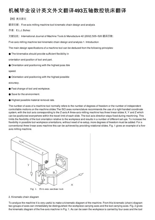
机械毕业设计英⽂外⽂翻译493五轴数控铣床翻译【附】英⽂原⽂翻译⽂献:Five-axis milling machine tool kinematic chain design and analysis作者:E.L.J. Bohez⽂献出处:International Journal of Machine Tools & Manufacture 42 (2002) 505–520 翻译页数:Five-axis milling machine tool kinematic chain design and analysis 1. IntroductionThe main design specifications of a machine tool can be deduced from the following principles:● The kinematics should provide sufficient flexibility inorientation and position of tool and part.● Orientation and positioning with the highest poss iblespeed.● Orientation and positioning with the highest possibleaccuracy.● Fast change of tool and workpiece.● Save for the environment.● Highest possible material removal rate.The number of axes of a machine tool normally refers to the number of degrees of freedom or the number of independent controllable motions on the machine slides.The ISO axes nomenclature recommends the use of a right-handed coordinate system, with the tool axis corresponding to the Z-axis.A three-axis milling machine has three linear slides X, Y and Z which can be positioned everywhere within the travel limit of each slide. The tool axis direction stays fixed during machining. This limits the flexibility of the tool orientation relative to the workpiece and results in a number of different set ups. To increase the flexibility in possible tool workpiece orientations, without need of re-setup, more degrees of freedom must be added. For a conventional three linear axes machine this can be achieved by providing rotational slides. Fig. 1 gives an example of a five-axis milling machine.2. Kinematic chain diagramTo analyze the machine it is very useful to make a kinematic diagram of the machine. From this kinematic (chain) diagram two groups of axes can immediately be distinguished: the workpiece carrying axes and the tool carrying axes. Fig. 2 gives the kinematic diagram of the five-axis machine in Fig. 1. As can be seen the workpiece is carried by four axes and the toolonly by one axis.The five-axis machine is similar to two cooperating robots, one robot carrying the workpiece and one robot carrying the tool.Five degrees of freedom are the minimum required to obtain maximum flexibility in tool workpiece orientation,this means that the tool and workpiece can be oriented relative to each other under any angle. The minimum required number of axes can also be understood from a rigid body kinematics point of view. To orient two rigid bodies in space relative to each other 6 degrees of freedom are needed for each body (tool and workpiece) or 12 degrees. However any common translation and rotation which does not change the relative orientation is permitted reducing the number of degrees by 6. The distance between the bodies is prescribed by the toolpath and allows elimination of an additional degree of freedom, resulting in a minimum requirement of 5 degrees.3.Literature reviewOne of the earliest (1970) and still very useful introductions to five-axis milling was given by Baughman [1]clearly stating the applications. The APT language was then the only tool to program five-axis contouring applications.The problems in postprocessing were also clearly stated by Sim [2] in those earlier days of numerical control and most issues are still valid. Boyd in Ref.[3] was also one of the early introductions. Bez iers’ book[4] is also still a very useful introduction. Held [5] gives a very brief but enlightening definition of multi-axis machining in his book on pocket milling. A recent paper applicable to the problem of five-axis machine workspace computation is the multiple sweeping using the Denawit-Hartenberg representation method developed by Abdel-Malek and Othman [6].Many types and design concepts of machine tools which can be applied to five-axis machines are discussed in Ref. [7] but not specifically for the five-axis machine.he number of setups and the optimal orientation of the part on the machine table is discussed in Ref.[8]. A review about the state of the art and new requirements for tool path generation is given by B.K. Choi et al. [9].Graphic simulation of the interaction of the tool and workpiece is also a very active area of research and a good introduction can be found in Ref. [10].4. Classification of five-axis machines’ kinematic structureStarting from Rotary (R) and Translatory (T) axes four main groups can be distinguished: (i) three T axes and two R axes; (ii) two T axes and three R axes; (iii) one T axis and four R axes and (iv) five R axes. Nearly all existing five-axis machine tools are in group (i). Also a number of welding robots, filament winding machines and laser machining centers fall in this group. Only limited instances of five-axis machine tools in group (ii)exist for the machining of ship propellers. Groups (iii)and (iv) are used in the design of robots usually with more degrees of freedom added.The five axes can be distributed between the workpiece or tool in several combinations. A first classification can be made based on the number of workpiece and tool carrying axes and the sequence of each axis in the kinematic chain.Another classification can be based on where the rotary axes are located, on the workpiece side or tool side. The five degrees of freedom in a Cartesian coordinates based machine are: three translatory movements X,Y,Z (in general represented as TTT) and two rotational movements AB, AC or BC (in general represented as RR).Combinations of three rotary axes (RRR)and two linear axes (TT) are rare. If an axis is bearing the workpiece it is the habit of noting it with an additional accent. The five-axis machine in Fig. 1 can be characterized by XYABZ. The XYAB axes carry the workpiece and the Z-axis carries the tool. Fig. 3 shows a machine of the type XYZAB , the three linear axes carry the tool and the two rotary axes carry the workpiece.5. Workspace of a five-axis machineBefore defining the workspace of the five-axis machine tool, it is appropriate to define the workspace of the tool and the workspace of the workpiece. The workspace of the tool is the space obtained by sweeping the tool reference point (e.g. tool tip) along the path of the tool carrying axes. The workspace of the workpiece carrying axes is defined in the same way (the center of the machine table can be chosen as reference point).These workspaces can be determined by computing the swept volume [6].Based on the above-definitions some quantitative parameters can be defined which are useful for comparison, selection and design of different types of machines.6.Selection criteria of a five-axis machineIt is not the objective to make a complete study on how to select or design a five-axis machine for a certain application. Only the main criteria which can be used to justify the selection of a five-axis machine are discussed.6.1. Applications of five-axis machine toolsThe applications can be classified in positioning and contouring. Figs. 12 and 13 explain the difference between five-axispositioning and five-axis contouring.6.1.1. Five-axis positioningFig. 12 shows a part with a lot of holes and flat planes under different angles, to make this part with a three axis milling machine it is not possible to process the part in one set up. If a five-axis machine is used the tool can process. More details on countouring can be found in Ref. [13]. Applications of five-axis contouring are: (i) production of blades, such as compressor and turbine blades; (ii) injectors of fuel pumps; (iii) profiles of tires; (iv) medical prosthesis such as artificial heart valves; (v) molds made of complex surfaces.6.1.2. Five-axis contouringFig. 13 shows an example of five-axis contouring, tomachine the complex shape of the surface we need to control the orientation of the tool relative to the part during cutting. The tool workpiece orientation changes in each step. The CNC controller needs to control all the five-axes simultaneously during the material removal process. More details on countouring can be found in Ref. [13]. Applications of five-axis contouring are: (i) production of blades, such as compressor and turbine blades; (ii) injectors of fuel pumps; (iii) profiles of tires; (iv) medical prosthesis such as artificial heart valves; (v)molds made of complex surfaces.6.2. Axes configuration selectionThe size and weight of the part is very important as a first criterion to design or select a configuration. Very heavy workpieces require short workpiece kinematic chains. Also there is a preference for horizontal machine tables which makes it more convenient to fix and handle the workpiece. Putting a heavy workpiece on a single rotary axis kinematic chain will increase the orientation flexibility very much. It can be observed from Fig. 4that providing a single horizontal rotary axis to carry the workpiece will make the machine more flexible. In most cases the tool carrying kinematic chains will be kept as short as possible because the toolspindle drive must also be carried.6.3.five-axes machining of jewelryA typical workpiece could be a flower shaped part as in Fig. 14. This application is clearly contouring. The part will be relatively small compared to the tool assembly. Also small diameter tools will require a high speed spindle. A horizontalrotary table would be a very good option as the operator will have a good view of the part (with range 360°). All axes as workpiece carrying axes would be a good choice because the toolspindlecould be fixed and made very rigid. There are 20 ways in which the axes can be combined in the workpiece kinematic chain (Section 4.2.1). Here only two kinematic chains will be considered. Case one will be a T T T R R kinematic chain shown in Fig. 15. Case two will be a R R T T T kinematic chain shown in Fig.16.For model I a machine with a range of X=300mmY=250 mm, Z=200 mm, C=n 360° and A=360°, and a machine tool table of 100 mm diameter will be considered. For this kinematic chain the tool workspace is a single point. The set of tool reference points which can be selected is also small. With the above machine travel ranges the workpiece workspace will be the space swept by the center of the machine table. If the centerline of the two rotary axes intersect in the reference point, a prismatic workpiece workspace will be obtained with as size XYZ or 300×250×200 mm3. If the centerlines of the two rotary axes do not intersect in the workpiece reference point then the workpiece workspace will be larger.It will be a prismatic shape with rounded edges. The radius of this rounded edge is the excentricity of the bworkpiece reference point relative to each centerline. Model II in Fig. 15 has the rotary axes at the beginning of the kinematic chain (R R T T T ). Here also two different values of the rotary axes excentricity will be considered. The same range of the axes as in model I is considered. The parameters defined in Section 5 are computed for each model and excentricity and summarized in Table 1. It can be seen that with the rotary axes at the end of the kinematic chain (model I), a much smaller machine tool workspace is obtained. There are two main reasons for this. The swept volume of the tool and workpiece WSTOOL WSWORK is much smaller for model I. The second reason is due to the fact that a large part of the machine tool workspace cannot be used in the case of model I, because of interference with the linear axes. The workspace utilization factor however is larger for the model I with no excentricity because the union of the tool workspace and workpiece workspace is relatively smaller compared with model I with excentricity e=50 mm. The orientation space index is the same for both cases if the table diameter is kept the same. Model II can handle much larger workpieces for the same range of linear axes as in model I. The rotary axes are here in the beginning of the kinematic chain, resulting in a much larger machine tool workspace then for model I. Also there is much less interference of the machine tool workspace with the slides. The other 18 possible kinematicchain selections will give index values somewhat in between the above cases.6.4. rotary table selectionTwo machines with the same kinematic diagram (T T R R T) and the same range of travel in the linear axes will be compared (Fig. 17). There are two options for the rotary axes: two-axis table with vertical table (model I), two-axis table with horizontal table (model II). Tables 2 and 3 give the comparison of the important features. It can be observed that reducing the range of the rotary axes increases the machine tool workspace. So model I will be more suited for smaller workpieces with operations which require a large orientation range, typically contouring applications. Model II will be suited for larger workpieces with less variation in tool orientation or will require two setups. This extra setup requirement could be of less importance then the larger size. The horizontal table can use pallets which transform the internal setup to external setup. The larger angle range in the B-axes 105 to +105, Fig. 17. Model I and model II T T R R T machines. compared to 45 to +20, makes model I more suited for complex sculptured surfaces, also because the much higher angular speed range of the vertical angular table. The option with the highest spindle speed should be selected and it will permit the use of smaller cutter diameters resulting in less undercut and smaller cutting forces. The high spindle speed will make the cutting of copper electrodes for die sinking EDM machines easier. The vertical table is also better for the chip removal. The large range of angular orientation, however, reduces the maximum size of the workpiece to about 300 mm and 100 kg. Model II with the same linear axes range as model I, but much smaller range in the rotation, can easily handle a workpiece of double size and weight. Model II will be good for positioning applications. Model I cannot be provided with automaticworkpiece exchange, making it less suitable for mass production. Model II has automatic workpiece exchange and is suitable for mass production of position applications. Model I could, however, be selected for positioning applications for parts such as hydraulic valve housings which are small and would require a large angular range.7.New machine concepts based on the Stewart platformConventional machine tool structures are based on Carthesian coordinates. Many surface contouring applications can be machined in optimal conditions only with five-axis machines. This five-axis machine structure requires two additional rotary axes. To make accurate machines, with the required stiffness, able to carry large workpieces, very heavy and large machines are required. As can be seen from the kinematic chain diagram of the classical five-axis machine design the first axis in the chain carries all the subsequent axes. So the dynamic responce will be limited by the combined inertia. A mechanism which can move the workpiece without having to carry the other axes would be the ideal. A new design concept is the use of a‘HEXAPOD’. Stewart [16] described the hexapod principle in 1965. It was first constructed by Gough and Whitehall [20] in 1954 and served as tire tester. Many possible uses were proposed but it was only applied to flight simulator platforms. Thereason was the complexity of the control of the six actuators. Recently with the amazing increase of speed and reduction in cost of computing, the Stewart platform is used by two American Companies in the design of new machine tools. The first machine is the VARIAX machine from the company Giddings and Lewis, USA. The second machine is the HEXAPOD from the Ingersoll company, USA. The systematic design of Hexapods and other similar systems is discussed in Ref. [17]. The problem of defining and determining the workspace of virtual axis machine tools is discussed in Ref. [18]. It can be observed from the design of the machine that once the position of the tool carrying plane is determined uniquely by the CL date (point + vector), it is still possible to rotate the tool carrying platform around the tool axis. This results in a large number of possible length combinations of the telescopic actuators for the same CL data.8.ConclusionTheoretically there are large number of ways in which a five-axis machine can be built. Nearly all classical Cartesian five-axis machines belong to the group with three linear and two rotational axes or three rotational axes and two linear axes. This group can be subdivided in six subgroups each with 720 instances.If only the instances with three linear axes are considered there are still 360instances in each group. The instances are differentiated based on the order of the axes in both tool and workpiece carrying kinematic chain.If only the location of the rotary axes in the tool and workpiece kinematic chain is considered for grouping five-axis machines withthree linear axes and two rotational axes, three groups can be distinguished. In the first group the two rotary axes are implemented in the workpiece kinematic chain. In the second group the two rotary axes are implemented in the tool kinematic chain.In the third group there is one rotary axis in each kinematic chain. Each group still has twenty possible instances.To determine the best instance for a specific application area is a complex issue. To facilitate this some indexes for comparison have been defined such as the machine tool workspace, workspace utilization factor, orientation space index, orientation angle index and machine tool space efficiency. An algorithm to compute the machine tool workspace and the diameter of the largest spherical dome which can be machined on the machine was outlined.The use of these indexes for two examples was discussed in detail. The first example considers the design of a five-axis machine for jewelry machining. The second example illustrates the selection of the rotary axes options in the case of a machine with the same range in linear axes.翻译题名:Five-axis milling machine tool kinematic chain design and analysis期刊与作者:E.L.J. Bohez出版社:International Journal of Machine Tools & Manufacture 42 (2002) 505–520●英⽂译⽂摘要:现如今五轴数控加⼯中⼼已经⾮常普及。
Numerical ControlOne of the most fundamental concepts in the area of advanced manufacturing technologies is numerical control (NC).Prior to the advent of NC, all machine tools were manual operated and controlled. Among the many limitations associated with manual control machine tools, perhaps none is more prominent than the limitation of operator skills. With manual control, the quality of the product is directly related to and limited to the skills of the operator . Numerical control representsthe first major step away from human control of machine tools.Numerical control means the control of machine tools and other manufacturing systems though the use of prerecorded, written symbolic instructions. Rather than operating a machine tool, an NC technician writes a program that issues operational instructions to the machine tool, For a machine tool to be numerically controlled , it must be interfaced with a device for accepting and decoding the p2ogrammed instructions, known as a reader.Numerical control was developed to overcome the limitation of human operator , and it has done so . Numerical control machines are more accurate than manually operated machines , they can produce parts more uniformly , they are faster, and the long-run tooling costs are lower . The development of NC led to the development of several other innovations in manufacturing technology:1.Electrical discharge machining.ser cutting.3.Electron beam welding.Numerical control has also made machine tools more versatile than their manually operated predecessors.An NC machine tool can automatically produce a wide variety of par4s , each involving an assortment of undertake the production of products that would not have been feasible from an economic perspective using manually controlled machine tools and processes.Like so many advanced technologies , NC was born in the laboratories of the Massachusetts Institute of Technology . The concept of NC was developed in the early 1950s with funding provided by the U.S Air Force .In its earliest stages , NC machines were able to make straight cuts efficiently and effectively.However ,curved paths were a problem because the machine tool had to be programmed to undertake a series of horizontal and vertical steps to produce a curve. The shorter is the straight lines making up the step ,the smoother is 4he curve . Each line segment in the steps had to be calculated.This problem led to the development in 1959 of the Automatically Programmed Tools (APT) language for NC that uses statementssimilar to English language to define the part geometry, describe the cutting tool configuration, and specify the necessary motions. The development of the APT language was a major step forward in the further development of NC technology. The original NC system were vastly different from those used punched paper , which was later to replaced by magnetic plastic tape .A tape reader was used to interpret the instructions written on the tape for the machine .Together, all /f this representedgiant step forward in the control of machine tools . However ,there were a number of problems with NC at this point in its development.A major problem was the fragility of the punched paper tape medium . It was common for the paper containing the programmed instructions to break or tear during a machining process, This problem was exacerbated by the fact that each successive time a part was produced on a machine tool, the paper tape carrying the programmed instructions had to rerun thought the reader . If itwas necessary to produce 100 copies of a given part , it was also necessary to run the paper tape thought the reader 100 separate times . Fragile paper tapes simply could not withstand the rigorsof shop floor environment and this kind of repeated use.This led to the development of a special magnetic tape . Whereas the paper tape carried the programmed instructions as a series of holes punched in the tape , theThis most important of these was that it was difficult or impossible to change the instructions entered on the tape . To make even the most minor adjustments in a program of instructions, it was necessary to interrupt machining operations and make a new tape. It was also still necessary to run the tape thought the reader as many times as there were parts to be produced . Fortunately, computer technology become a reality and soon solved the problems of NC, associated with punched paper and plastic tape.The development of a concept known as numerical control (DNC) solve the paper and plastic tape problems associatedwith numerical control by simply eliminating tape as the medium for carrying the programmed instructions . In direct numerical control, machine tools are tied, via a data transmission link, to a host computer and fed to the machine tool as needed via the data transmission linkage. Direct numerical control represented a major step forward over punched tape and plastic tape. However ,it is subject to the same limitation as all technologies that depend on a host computer. When the host computer goes down , the machine tools also experience down time . This problem led to the development of computer numerical control.The development of the microprocessor allowed for the development of programmable logic controllers (PLC) and microcomputers . These two technologies allowed for the development of computer numerical control (CNC).With CNC , each machine tool has a PLC or a microcomputer that serves the same purpose. This allows programs to be input and stored at each individual machine tool. CNC solved the problems associated downtime of the host computer , but it introduced another problem known as data management . The same program might be loaded on ten different microcomputers with no communication among them. This problem is in the process of being solved by local area networks that connectDigital Signal ProcessorsThere are numerous situations where analog signals to be processed in many ways, likefiltering and spectral analysis , Designing analog hardware to perform these functions is possible but has become less and practical, due to increased performance requirements, flexibility needs , and the need to cut down on development/testing time .It is in other words difficult pm design analog hardware analysis of signals.The act of sampling an signal into thehat are specialised for embedded signal processing operations , and such a processor is called a DSP, which stands for Digital Signal Processor . Today there are hundreds of DSP families from as many manufacturers, each one designed for a particular price/performance/usagegroup. Many of the largest manufacturers, like Texas Instruments and Motorola, offer both specialised DSP for certain'fieslds like motor -control or modems ,and general highp- erformance DSP ' s that can perform broad ranges of processingtasks. Development kits an' software are also available , and there are companies making software development tools for DSP' sth at allows the programmer to implement complex processing algorithms using simple “drag ‘n' drop ” methodologies.DSP's more or less fall into two categories depending on the underlying architecture-fixed-point and floating-point. The fixed-point devices generally operate on 16-bit words, while the floating-point devices operate on 32-40 bits floating-point words. Needless to say , the fixed-point devices are generally cheaper . Another important architectural difference is that fixed-point processors tend to have an accumulator architecture, with only one “generaplurpose ”register , making them quite tricky to program and more importantly ,making C-compilers inherently inefficient. Floating-point DSP'sbehave more like common general-purpose CPU's ,with re g i s-tfei l er s .There are thousands of different DSP 's on the market, and it is difficult task finding themost suitable DSP for a project. The best way is probably to set up a constraint and wishlist, and try to compare the processors from the biggest manufacturers against it.The “big four ” manufacturers of DSPs: Texas Instruments, Motorola, AT&T and Analog Devices.Digital-to-analog conversionIn the case of MPEG-Audio decoding , digital compressed data is fed into the DSP which performs the decoding , then the decoded samples have to be converted back into the analog domain , and the resulting signal fed an amplifier or similar audio equipment . This digital to analog conversion (DCA) is performed by a circuit with the same name & Different DCA provide different performance and quality , as measured by THD (Total harmonic distortion ), number of bits,linearity , speed, filter characteristics and other things.The TMS320 family DQP of Texas InstrumentsThe TLS320family consists of fixed-point, floating-point, multiprocessor digital signal processors (D[Ps) , and foxed-point DSP controllers. TMS320 DSP have an architecture designed specifically for real-time signal processing . The' F/C240 is a number of the 'C2000DSP platform , and is optimized for control applications. The 'C24x series o controllers combines this real-time processing capability with controller peripherals to create an ideal solution for control system applications. The following characteristics make the TMS320 family the right choice for a wide range of processing applications:--- Very flexible instruction set--- Inherent operational flexibility---High-speed performance---Innovative parallel architecture---Cost effectivenessDevices within a generation of the TMS320 family have the same CPU structure but differenton-chip memory and peripheral configurations. Spin-off devices use new combinations of On-chip memory and peripherals to satisfy a wide range of needs in the worldwide electronics market. By integrating memory and peripherals onto a single chip , TMS320 devices reduce system costs and save circuit board space.The 16-bit ,fixed-point DSP core of the ‘C24xdevicesprovides analog designers a digital solution that does not sacrifice the precision and performance of their system performance can be enhanced through the use of advanced control algorithms for techniquessuch as adaptive control , Kalman filtering , andstate control. The ‘ C24x DSP controller offer reliability and programmability . Analog control systems, on the other hand ,are hardwiredsolutions and can experience performance degradation due to aging , component tolerance, and drift.The high-speed central processing unit (CPU) allows the digital designer to process algorithms in real time rather than approximate results with look-up tables. The instruction set of these DSP controllers, which incorporates both signal processing instructions and general-purpose control functions, coupled with the extensive development time and provides the same ease of use astraditional 8-and 16-bit microcontrollers. The instruction set also allows you to retain your software investment when moving from other general-purpose‘ C2xx generation ,source code compatible with the ' C2gxeneration , and upwardly source code compatible with the ‘ C5x generation of DSPs from Texas Instruments.The ‘C24x architecture is also w-eslul ited for processing control signals. It uses a 16-bit word length along with 32-bit registers for storing intermediate results, and has two hardware shifters available to scale numbers independently of the CPU . This combination minimizes quantization and truncation errors, and increases p2ocessing power for additional functions. Such functions might include a notch filter that could cancel mechanical resonancesin a system or an estimation technique that could eliminate state sensors in a system.The ‘ C24xDSP controllers take advantage of an set of peripheraful nctions that allow Texas Instruments to quickly configure various series members for different price/ performance points or for application optimization.This library of both digital and mixed-signal peripherals includes:---Timers---Serial communications ports (SCI,SPI)---Analog-to-digital converters(ADC)---Event manager---System protection, such as low-voltage and watchdog timerThe DSP controller peripheral library is continually growing and changing to suit the of tomorrow ' s embedded control matrpkleace.The TMS320F/C240 is the first standard device introduced in the ‘ 24x series of DScontrollers. It sets the standard for a singlec-hip digital motor controller. The ‘ 240 can execute 20 MIPS. Almost all instructions are executed in a simple cycle of 50 ns . This high performance allows real-time execution of very comple8 control algorithms, such as adaptive control and Kalman filters. Very high sampling rates can also be used to minimize loop delays.The ‘ 240 has the architectural features necessfaorryhigh-speed signal processing anddigital control functions, and it has the peripherals needed to provide a single-chip solution for motor control applications. The ‘ 240is manufactured using submicron CMOS technology, achieving a log power dissipation rating . Also included are several power-down modes for further power savings. Some applications that benefit from the advanced processing power of the ‘ 240 include: ---Industrial motor drives---Power inverters and controllers---Automotive systems, such as electronic power steering , antilock brakes, and climate control---Appliance and HVAC blower/ compressor motor controls---Printers, copiers, and other office products---Tape drives, magnetic optical drives, and other mass storage products---Robotic and CNC milling machinesTo function as a system manager, a DSP must have robust on-chip I/O and other peripherals. The event manager of the ‘ 240is unlike any other available on a DSP . This application-optimized peripheral unit , coupled with the high performance DSP core, enables the use of advanced control techniques for high-precision and high-efficiency full variable-speed control of all motor types.Include in the event manager are special pulse-width modulation (PWM) generation functions, such as a programmable dead-band function and a space vector PWM state machine for 3-phase motors that provides state-of-the-art maximum efficiency in the switching of power transistors.There independent up down timers, each with it 'oswn compare register, support the generation of asymmetric (noncentered) as well as symmetric (centered) PWM waveforms.Open-Loop and Closed-Loop ControlOpen-loop Control SystemsThe word automatic implies that there is a certain amount of sophistication in the control system. By automatic, it generally means That the system is usually capable of adapting to avariety of operating conditions and is able to respond to a class of inputs satisfactorily . However , not any type of control system has the automatic feature. Usually , the automatic feature is achieved by feed.g the feedback structure, it is called an open-loop system , which is the simplest and most economical type of control system.inaccuracy lies in the fact that one may not know the exact characteristics of the further ,which has a definite bearing on the indoor temperature. This alco points to an important disadvantageof the performance of an open -loop control system, in that the system is not capable of adapting to variations in environmental conitions or to external disturbances. In the case of the furnace control, perhaps an experienced person can provide control for a certain desired temperature in the house; but id the doors or windows are opened or closed intermittently during the operating period, the final temperature inside the house will not be accurately regulated by the open-loop control.An electric washing machine is another typical example of an open-loop system , because the amount of wash time is entirely determined by the judgment and estimation of the human operator . A true automatic electric washing machine should have the means of checking the cleanliness of the clothes continuously and turn itsedt off when the desired degised of cleanliness is reached.Closed-Loop Control SystemsWhat is missing in the open-loop control system for more accurate and more adaptable control is a link or feedback from the output to the input of the system . In order to obtain more accurate bontrol, the controlled signal c(t) must be fed back and compared with the reference input , and an actuating signal proportional to the difference of the output and the input must be sent through the system to correct the error. A system with one or more feedback pat(s like that just described is called a closed-loop system. human being are probably the most complex and sophisticated feedback control system in existence. A human being may be considered to be a control system with many inputs and outputs, capable of carrying out highly complex operations.To illustrate the human being as a feedback control system , let us consider that the objective is to reach for an object on aperform the task. The eyes serve as a sensing device which feeds back continuously the position of the hand . The distance between the hand and the object is the error , which is eventually brought to zero as the hand reacher the object. This is a typical example of closed-loop control. However , if one is told to reach for the object and then is blindolded, one can only reach toward the object by estimating its exact position. It isAs anther illustrative example of a closed-loop control system, shows the block diagram of the rudder control system ofThe basic alements and the bloca diagram of a closed-loop control system are shown in fig. In general , the configuration of a feedback control system may not be constrained to that of fig & . In complex systems there may be multitude of feedback loops and element blocks.数控在先进制造技术领域最根本的观念之一是数控( NC。
数控机床外文文献翻译、中英文翻译原文一CNC machine toolsOutdate, J. and Joe, J. Configuration Synthesis of Machining Centers with Tool,JohnWiley & sons, 2001While the specific intention and application for CNC machines vary from one machine type to another, all forms of CNC have common benefits. Here are but a few of the more important benefits offered by CNC equipment.The first benefit offered by all forms of CNC machine tools is improved automation. The operator intervention related to producing work pieces can be reduced or eliminated. Many CNC machines can run unattended during their entire machining cycle, freeing the operator to do other tasks. This gives the CNC user several side benefits including reduced operator fatigue, fewer mistakes caused by human error, and consistent and predictable machining time for each work piece. Since the machine will be running under program control, the skill level required of the CNC operator (related to basic machining practice) is also reduced as compared to a machinist producing work pieces with conventional machine tools.The second major benefit of CNC technology is consistent and accurate work pieces. T oday's CNC machines boast almost unbelievable accuracy and repeatability specifications. This means that once a program is verified, two, ten, or one thousand identical work pieces can be easily produced with precision and consistency.A third benefit offered by most forms of CNC machine toolsis flexibility. Since these machines are run from programs, running a different workpiece is almost as easy as loading a different program. Once a program has been verified and executed for one production run, it can be easily recalled the next time the workpiece is to be run. This leads to yet another benefit, fast change over. Since these machines are very easy to set up and run, and since programs can be easily loaded, they allow very short setup time. This is imperative with today's just-in-time (JIT) product requirements.Motion control - the heart of CNCThe most basic function of any CNC machine is automatic, precise, and consistent motion control. Rather than applying completely mechanical devices to cause motion as is required on most conventional machine tools, CNC machines allow motion control in a revolutionary manner2. All forms of CNC equipment have two or more directions of motion, called axes. These axes can be precisely and automatically positioned along their lengths of travel. The two most common axis types are linear (driven along a straight path) and rotary (driven along a circular path).Instead of causing motion by turning cranks and handwheels as is required on conventional machine tools, CNC machines allow motions to be commanded through programmed commands. Generally speaking, the motion type (rapid, linear, and circular), the axes to move, the amount of motion and the motion rate (federate) are programmable with almost all CNC machine tools.A CNC command executed within the control tells the drive motor to rotate a precise number of times. The rotation of the drive motor in turn rotates the ball screw.And the ball screw drives the linear axis (slide). A feedbackdevice (linear scale) on the slide allows the control to confirm that the commanded number of rotations has taken place3. Refer to fig.1.fig.1 typical drive system of a CNC machine toolThough a rather crude analogy, the same basic linear motion can be found on a common table vise. As you rotate the vise crank, you rotate a lead screw that, in turn, drives the movable jaw on the vise. By comparison, a linear axis on a CNC machine tool is extremely precise. The number of revolutions of the axis drive motor precisely controls the amount of linear motion along the axis.How axis motion is commanded - understanding coordinate systemsIt would be infeasible for the CNC user to cause axis motion by trying to tell each axis drive motor how many times to rotate in order to command a given linear motion amount4. (This would be like having to figure out how many turns of the handle on a table vise will cause the movable jaw to move exactly one inch!) Instead, all CNC controls allow axis motion to be commanded in a much simpler and more logical way by utilizing some form of coordinate system. The two most popular coordinate systems used with CNC machines are the rectangular coordinate system and the polar coordinate system. By far, the more popular of these two is the rectangular coordinate system.The program zero point establishes the point of reference for motion commands in a CNC program. This allows the programmer to specify movements from a common location. If program zero is chosen wisely, usually coordinates needed forthe program can be taken directly from the print.With this technique, if the programmer wishes the tool to be sent to a position one inch to the right of the program zero point, X1.0 is commanded. If the programmer wishes the tool to move to a position one inch above the program zero point, Y1.0 is commanded. The control will automatically determine how many times to rotate each axis drive motor and ball screw to make the axis reach the commanded destination point . This lets the programmer command axis motion in a very logical manner. Refer to fig.2, 3.fig.2, 3.Understanding absolute versus incremental motionAll discussions to this point assume that the absolute mode of programming is used6. The most common CNC word used to designate the absolute mode is G90. In the absolute mode, the end points for all motions will be specified from the program zero point. For beginners, this is usually the best and easiest method of specifying end points for motion commands. However, there is another way of specifying end points for axis motion.In the incremental mode (commonly specified by G91), endpoints for motions are specified from the tool's current position, not from program zero. With this method of commanding motion, the programmer must always be asking "How far should I move the tool?" While there are times when the incremental mode can be very helpful, generally speaking, this is the more cumbersome and difficult method of specifying motion and beginners should concentrate on using the absolute mode.Be careful when making motion commands. Beginners have the tendency to think incrementally. If working in the absolute mode (as beginners should), the programmer should always be asking "To what position should the tool be moved?" This position is relative to program zero, NOT from the tools current position.Aside from making it very easy to determine the current position for any command, another benefit of working in the absolute mode has to do with mistakes made during motion commands. In the absolute mode, if a motion mistake is made in one command of the program, only one movement will be incorrect. On the other hand, if a mistake is made during incremental movements, all motions from the point of the mistake will also be incorrect.Assigning program zeroKeep in mind that the CNC control must be told the location of the program zero point by one means or another. How this is done varies dramatically from one CNC machine and control to another8. One (older) method is to assign program zero in the program. With this method, the programmer tells the control how far it is from the program zero point to the starting position of the machine. This is commonly done with a G92 (or G50) command at least at the beginning of the program and possiblyat the beginning of each tool.Another, newer and better way to assign program zero is through some form of offset. Refer to fig.4. Commonly machining center control manufacturers call offsets used to assign program zero fixture offsets. Turning center manufacturers commonly call offsets used to assign program zero for each tool geometry offsets.fig.4 assign program zero through G54Flexible manufacturing cellsA flexible manufacturing cell (FMC) can be considered as a flexible manufacturing subsystem. The following differences exist between the FMC and the FMS:1.An FMC is not under the direct control of thecentral computer. Instead, instructions from the centralcomputer are passed to the cell controller.2.The cell is limited in the number of part families itcan manufacture.The following elements are normally found in an FMC:Cell controllerProgrammable logic controller (PLC)More than one machine toolA materials handling device (robot or pallet)The FMC executes fixed machining operations with parts flowing sequentially between operations.High speed machiningThe term High Speed Machining (HSM) commonly refers to end milling at high rotational speeds and high surface feeds. For instance, the routing of pockets in aluminum airframe sections with a very high material removal rate1. Refer to fig.5 for the cutting data designations and for mulas. Over the past 60 years, HSM has been applied to a wide range of metallic and non-metallic workpiece materials, including the production of components with specific surface topography requirements and machining of materials with hardness of 50 HRC and above. With most steel components hardened to approximately 32-42 HRC, machining options currently include:Fig.5 cutting datarough machining and semi-finishing of the material in its soft (annealed) condition heat treatment to achieve the final required hardness = 63 HRC machining of electrodes and Electrical Discharge Machining (EDM) of specific parts of dies and moulds (specifically small radii and deep cavities with limited accessibility for metal cutting tools) finishing and super-finishing of cylindrical/flat/cavity surfaces with appropriate cemented carbide, cermets, solid carbide, mixed ceramic or polycrystalline cubic boron nitride (PCBN)For many components, the production process involves acombination of these options and in the case of dies and moulds it also includes time consuming hand finishing. Consequently, production costs can be high and lead times excessive.It is typical in the die and mould industry to produce one or just a few tools of the same design. The process involves constant changes to the design, and because of these changes there is also a corresponding need for measuring and reverse engineering.The main criteria are the quality level of the die or mould regarding dimensional, geometric and surface accuracy. If the quality level after machining is poor and if it cannot meet the requirements, there will be a varying need of manual finishing work. This work produces satisfactory surface accuracy, but it always has a negative impact on the dimensional and geometric accuracy.One of the main aims for the die and mould industry has been, and still is, to reduce or eliminate the need for manual polishing and thus improve the quality and shorten the production costs and lead times.Main economical and technical factors for the development of HSMSurvivalThe ever increasing competition in the marketplace is continually setting new standards. The demands on time and cost efficiency is getting higher and higher. This has forced the development of new processes and production techniques to take place. HSM provides hope and solutions...MaterialsThe development of new, more difficult to machine materials has underlined the necessity to find new machining solutions.The aerospace industry has its heat resistant and stainless steel alloys. The automotive industry has different bimetal compositions, Compact Graphite Iron and an ever increasing volume of aluminum3. The die and mould industry mainly has to face the problem of machining high hardened tool steels, from roughing to finishing.QualityThe demand for higher component or product quality is the result of ever increasing competition. HSM, if applied correctly, offers a number of solutions in thisarea. Substitution of manual finishing is one example, which is especially important on dies and moulds or components with a complex 3D geometry.ProcessesThe demands on shorter throughput times via fewer setups and simplified flows (logistics) can in most cases, be solved by HSM. A typical target within the die and mould industry is to completely machine fully hardened small sized tools in one setup. Costly and time consuming EDM processes can also be reduced or eliminated with HSM.Design & developmentOne of the main tools in today's competition is to sell products on the value of novelty. The average product life cycle on cars today is 4 years, computers and accessories 1.5 years, hand phones 3 months... One of the prerequisites of this development of fast design changes and rapid product development time is the HSM technique.Complex productsThere is an increase of multi-functional surfaces on components, such as new design of turbine blades giving newand optimized functions and features. Earlier designs allowed polishing by hand or with robots (manipulators). Turbine blades with new, more sophisticated designs have to be finished via machining and preferably by HSM . There are also more and more examples of thin walled workpiece that have to be machined (medical equipment, electronics, defense products, computer parts).Production equipmentThe strong development of cutting materials, holding tools, machine tools, controls and especially CAD/CAM features and equipment, has opened possibilities that must be met with new production methods and techniques5.Definition of HSMSalomon's theory, "Machining with high cutting speeds..." on which, in 1931, took out a German patent, assumes that "at a certain cutting speed (5-10 times higher than in conventional machining), the chip removal temperature at the cutting edge will start to decrease...".See fig.6.Fig.6 chip removal temperature as a result of the cutting speedGiven the conclusion:" ... seems to give a chance to improve productivity in machining with conventional tools at high cutting speeds..."Modern research, unfortunately, has not been able to verifythis theory totally. There is a relative decrease of the temperature at the cutting edge that starts at certain cutting speeds for different materials.The decrease is small for steel and cast iron. But larger for aluminum and other non-ferrous metals. The definition of HSM must be based on other factors.Given today's technology, "high speed" is generally accepted to mean surface speeds between 1 and 10 kilometers perminute, or roughly 3 300 to 33 000 feet per minute. Speeds above 10 km/min are in the ultra-high speed category, and are largely the realm of experimental metal cutting. Obviously, the spindle rotations required to achieve these surface cutting speeds are directly related to the diameter of the tools being used. One trend which is very evident today is the use of very large cutter diameters for these applications - and this has important implications for tool design.There are many opinions, many myths and many different ways to define HSM. Maintenance and troubleshooting Maintenance for a horizontal MCThe following is a list of required regular maintenance for a Horizontal Machining Center as shown in fig.7. Listed are the frequency of service, capacities, and type of fluids required. These required specifications must be followed in order to keep your machine in good working order and protect your warranty.Fig. 7 horizontal machining centerDailyTop off coolant level every eight hour shift (especially during heavy TSC usage).Check way lube lubrication tank level.Clean chips from way covers and bottom pan.Clean chips from tool changer.Wipe spindle taper with a clean cloth rag and apply light oil.WeeklyCheck for proper operation of auto drain on filter regulator. See fig. 8Fig. 8 way lube and pneumaticsOn machines with the TSC option, clean the chip basket on the coolant tank.Remove the tank cover and remove any sediment inside the tank. Be careful to disconnect the coolant pump from the controller and POWER OFF the control before working on the coolant tank. Do this monthly for machines without the TSC option.Check air gauge/regulator for 85 psi.For machines with the TSC option, place a dab of grease on the V-flange of tools. Do this monthly for machines without the TSC option.Clean exterior surfaces with mild cleaner. DO NOT usesolvents.Check the hydraulic counterbalance pressure according to the machine's specifications.Place a dab of grease on the outside edge of the fingers of the tool changer and run through all tools".MonthlyCheck oil level in gearbox. Add oil until oil begins dripping from over flow tube at bottom of sump tank.Clean pads on bottom of pallets.Clean the locating pads on the A-axis and the load station. This requires removing the pallet.Inspect way covers for proper operation and lubricate with light oil, if necessary.Six monthsReplace coolant and thoroughly clean the coolant tank.Check all hoses and lubrication lines for cracking.AnnuallyReplace the gearbox oil. Drain the oil from the gearbox, and slowly refill it with 2 quarts of Mobil DTE 25 oil.Check oil filter and clean out residue at bottom for the lubrication chart.Replace air filter on control box every 2 years.Mineral cutting oils will damage rubber based components throughout the machine.TroubleshootingThis section is intended for use in determining the solution to a known problem. Solutions given are intended to give the individual servicing the CNC a pattern to follow in, first, determining the problem's source and, second, solving the problem.Use common senseMany problems are easily overcome by correctly evaluating the situation. All machine operations are composed of a program, tools, and tooling. You must look at all three before blaming one as the fault area. If a bored hole is chattering because of an overextended boring bar, don't expect the machine to correct the fault.Don't suspect machine accuracy if the vise bends the part. Don't claim hole miss-positioning if you don't first center-drill the hole.Find the problem firstMany mechanics tear into things before they understand the problem, hoping that it will appear as they go. We know this from the fact that more than half of all warranty returned parts are in good working order. If the spindle doesn't turn, remember that the spindle is connected to the gear box, which is connected to the spindle motor, which is driven by the spindle drive, which is connected to the I/O BOARD, which is driven by the MOCON, which is driven by the processor. The moral here is doing replace the spindle drives if the belt is broken. Find the problem first; don't just replace the easiest part to get to.Don tinker with the machineThere are hundreds of parameters, wires, switches, etc., that you can change in this machine. Don't start randomly changing parts and parameters. Remember, there is a good chance that if you change something, you will incorrectly install it or break something else in the process6. Consider for a moment changing the processor's board. First, you have to download all parameters, remove a dozen connectors, replace the board, reconnect and reload, and if you make one mistake or bend one tiny pin itWON'T WORK. You always need to consider the risk of accidentally damaging the machine anytime you work on it. It is cheap insurance to double-check a suspect part before physically changing it. The less work you do on the machine the better.译文一数控机床虽然各种数控机床的功能和应用各不相同,但它们有着共同的优点。
外文翻译NUMERICAL CONTROLNumerical control(N/C)is a form of programmable automation in which the processing equipment is controlled by means of numbers,letters,and other symbols.The numbers,letters,and symbols are coded in an appropriate format to define a program of instructions for a particular work part or job.When the job changes,the program of instructions is changed.The capability to change the program is what makes N/C suitable for low-and medium-volume production.It is much easier to write programs th an to make major alterations of the processing equipment.There are two basic types of numerically controlled machine tools:point—to—point and continuous—path(also called contouring).Point—to—point machines use unsynchronized motors,with the result that the position of the machining head Can be assured only upon completion of a movement,or while only one motor is running.Machines of this type are principally used for straight—line cuts or for drilling or boring.The N/C system consists of the following comp onents:data input,the tape reader with the control unit,feedback devices,and the metal—cutting machine tool or other type of N/C equipment.Data input,also called “man—to—control link”,may be provided to the machine tool manually,or entirely by automatic means.Manual methods when used as the sole source of input data are restricted to a relatively small number of inputs.Examples of manually operated devices are keyboard dials,pushbuttons,switches,or thumbwheel selectors.These are located on a console near t he machine.Dials ale analog devices usually connected to a syn-chro-type resolver or potentiometer.In most cases,pushbuttons,switches,and other similar types of selectors aye digital input devices.Manual input requires that the operator set the controls fo r each operation.It is a slow and tediousprocess and is seldom justified except in elementary machining applications or in special cases.In practically all cases,information is automatically supplied to the control unit and the machine tool by cards,punched tapes,or by magnetic tape.Eight—channel punched paper tape is the most commonly used form of data input for conventional N/C systems.The coded instructions on the tape consist of sections of punched holes called blocks.Each block represents a machine function,a machining operation,or a combination of the two.The entire N/C program on a tape is made up of an accumulation of these successive data blocks.Programs resulting in long tapes all wound on reels like motion-picture film.Programs on relatively short tapes may be continuously repeated by joining the two ends of the tape to form a loop.Once installed,the tape is used again and again without further handling.In this case,the operator simply loads and unloads the parts.Punched tapes ale prepared on typ e writers with special tape—punching attachments or in tape punching units connected directly to a computer system.Tape production is rarelyerror-free.Errors may be initially caused by the part programmer,in card punching or compilation,or as a result of physical damage to the tape during handling,etc.Several trial runs are often necessary to remove all errors and produce an acceptable working tape.While the data on the tape is fed automatically,the actual programming steps ale done manually.Before the coded tape may be prepared,the programmer,often working with a planner or a process engineer, must select the appropriate N/C machine tool,determine the kind of material to be machined,calculate the speeds and feeds,and decide upon the type of tooling needed. The dimensions on the part print are closely examined to determine a suitable zero reference point from which to start the program.A program manuscript is then written which gives coded numerical instructions describing the sequence ofoperations that the machine tool is required to follow to cut the part to the drawing specifications.The control unit receives and stores all coded data until a complete block of information has been accumulated.It then interprets the coded instruction and directs the machine tool through the required motions.The function of the control unit may be better understood by comparing it to the action of a dial telephone,where,as each digit is dialed,it is stored.When the entire number has been dialed,the equipment becomes activated and the call is completed.Silicon photo diodes,located in the tape reader head on the control unit,detect light as it passes through the holes in the moving tape.The light beams are converted to electrical energy,which is amplified to further strengthen the signal.The signals are then sent to registers in the control unit, where actuation signals are relayed to the machine tool drives.Some photoelectric devices are capable of reading at rates up to 1000 characters per second.High reading rates are necessary to maintain continuous machine—tool motion;otherwise dwell marks may be generated by the cutter on the part during contouring operations.The reading device must be capable of reading data blocks at a rate faster than the control system can process the data.A feedback device is a safeguard used on some N/C installations to constantly compensate for errors between the commanded position and the actual location of the moving slides of the machine tool.An N /C machine equipped with this kind of a direct feedback checking device has what is known as a closed-loop system.Positioning control is accomplished by a sensor which,during the actual operation,records the position of the slides and relays this information back to the control unit.Signals thus received ale compared to input signals on the tape,and any discrepancy between them is automatically rectified.In an alternative system,called an open—loop system,the machine is positioned solely by stepping motor drives in response to commands by a controllers.There are three basic types of NC motions, as follows: Point-to-point or Positional Control In point-to-point control the machine tool elements (tools, table, etc.) are moved to programmed locations and the machining operations performed after the motion s are completed. The path or speed of movement between locations is unimportant; only the coordinates of the end points of the motions are accurately controlled. This type of control is suitable for drill presses and some boring machines, where drilling, t apping, or boring operations must be performed at various locations on the work piece. Straight-Line or Linear Control Straight-Line control systems are able to move the cutting tool parallel to one of the major axes of the machine tool at a controlled rate suitable for machining. It is normally only possible to move in one direction at a time, so angular cuts on the work piece are not possible, consequently, for milling machines, only rectangular configurations can be machined or for lathes only surfaces parall el or perpendicular to the spindle axis can be machined. This type of controlled motion is often referred to as linear control or a half-axis of control. Machines with this form of control are also capable ofpoint-to-point control.Continuous Path or Contouring Control In continuous path control the motions of two or more of the machine axes are controlled simultaneously, so that the position and velocity of the can be tool are changed continuously. In this way curves and surfaces can be machined at a controlled feed rate. It is the function of the interpolator in the controller to determine the increments of the individual controlled axes of the machines necessary to produce the desired motion. This type of control is referred to as continuous control or a full axis of control.Some terminology concerning controlled motions for NC machines has been introduced. For example, some machines are referred to asfour-or five-or even six-axis machines. For a vertical milling machine three axes of control are fairly obvious, these being the usual X, Y, Z coordinate directions. A fourth or fifth axis of control would imply some form of rotary table to index the work piece or possibly to provide angular motion of the work head. Thus, in NC terminology an axis of control is any controlled motion of the machine elements (spindles, tables, etc). A further complication is use of the term half-axis of control; for example, many milling machines are referred to as 2.5-axis machine. This means that continuous control is possib le for two motions (axes) and only linear control is possible for the third axis. Applied to vertical milling machines, 2.5axis control means contouring in the X, Y plane and linear motion only in the Z direction. With these machines three-dimensional objects have to be machined with water lines around the surface at different heights. With an alternative terminology the same machine could be called a 2CL machine (C for continuous, L for linear control). Thus, a milling machine with continuous control in th e X, Y, Z directions could be termed be a three-axis machine or a 3c machine, Similarly, lathes are usually two axis or 2C machines. The degree of work precision depends almost entirely upon the accuracy of the lead screw and the rigidity of the machine st ructure.With this system.there is no self-correcting action or feedback of information to the control unit.In the event of an unexpected malfunction,the control unit continues to put out pulses of electrical current.If,for example,the table on a N/C milling machine were suddenly to become overloaded,no response would be sent back to the controller.Because stepping motors are not sensitive to load variations,many N/C systems are designed to permit the motors to stall when the resisting torque exceeds the motor torque.Other systems are in use,however,which in spite of the possibility of damage to the machine structure or to the mechanical system,ale designed with special high—torque steppingmotors.In this case,the motors have sufficient capacity to “overpower” the system in the event of almost any contingency.The original N/C used the closed—loop system.Of the two systems,closed and open loop,closed loop is more accurate and,as a consequence,is generally more expensive.Initially,open—loop systems were used almost entirely for light-duty applications because of inherent power limitations previously associated with conventional electric stepping motors.Recent advances in the development of electro hydraulic stepping motors have led to increasingly heavier machin e load applications.数控技术数控是可编程自动化技术的一种形式,通过数字、字母和其他符号来控制加工设备。
Development and maintenance of CNC technology Numerical control technology and equipment is the development of new high-tech industry and cutting-edge enabling technology, industry and the most basic equipment. The world information industry, biological industry, aviation, aerospace and other defense industry widely used numerical techniques to improve manufacturing capacity and level, to improve the adaptability of the market and competitiveness. Industrial countries and CNC numerical control technology and equipment will also be listed as countries of strategic materials, not only to develop their own numerical control technology and industry, and in "sophisticated" technology and equipment, numerical control key aspects of the policy of closures and restrictions. Therefore, efforts to develop advanced numerical control technology as the core manufacturing technology has become the world's developed countries to accelerate economic development, enhance the comprehensive national strength and an important way to statehood.Part I: the development of CNC machine tools trends in individual1. High speed, high accuracy, high reliabilityHigh speed: To improve the speed and increase feed spindle speed.High precision: the precision from micron to sub-micron level, and even the nano-level (high reliability: the reliability of numerical control system generally higher than the reliability of numerical control equipment more than an order of magnitude, but not the higher the better reliability because the goods by the cost performance constraints.2. CompositeComposite function CNC machine tool development, its core is in a single machine to complete the turning, milling, drilling, tapping, reaming and reaming and other operating procedures, thereby increasing the efficiency and precision machine tools to improve production flexibility.3. IntelligentIntelligent content included in all aspects of the numerical control system: the pursuit of processing efficiency and processing quality of intelligence; to improve the performance and the use of convenient connections and other aspects of intelligence; simplify programming, simplifying operational intelligence; also like the intelligent automatic programming, intelligent man-machine interface, as well as intelligent diagnostics, intelligent monitoring and other aspects, to facilitate system diagnostics and maintenance.4. Flexible, integratedThe world of CNC machine tools to the development trend of flexible automation systems are: from the point (CNC single, composite machining centers and CNC machine tools), line (FMC, FMS, FTL, FML) to the surface (Section workshop independent manufacturing island FA) , body (CIMS, distributed network integrated manufacturing system) direction, the other to focus on applied and economic direction. Flexible automation technology is the industry to adapt to dynamic market demands and quickly update the primary means of product is the main trend of national manufacturing industry is the basis for the field of advanced manufacturing technology.Second, personalization is the adaptability of the market trendsToday's market, gradually formed the pattern of international cooperation, the products becoming more competitive, efficient and accurate processing of the escalating demand means, the user's individual requirements become increasingly strong, professional, specialization, more and more high-tech machine tools by the users of all ages.Third, the open architecture trend isThe core of a new generation of CNC system development is open. Open software platform and hardware platforms are open systems, modular, hierarchical structure, and through out the form to provide a unified application interface.CNC system to address the closure of the traditional CNC applications and industrial production problems. At present, many countries of open CNC system, CNC system has become an open numerical control system of the future of the road. The open numerical control system architecture specification, communication specifications, configuration specifications, operating platform, function libraries and CNC numerical control system software development tools, system function is the core of the current study. Network numerical control equipment is nearly two years of a new focus. NC network equipment will greatly satisfy the production lines, manufacturing systems, manufacturing information integration needs of enterprises, but also achieve new manufacturing model, such as agile manufacturing, virtual enterprises, global manufacturing the base unit. Some well-known at home and abroad, and CNC CNC machine tools manufacturing company inPart II: Machine MaintenanceCNC machine tools is electronic technology, measurement technology, automation technology, semiconductor technology, computer technology and electrical technology, and integrated set of automation equipment, high precision, high efficiency and high flexibility. CNC machine tools is a process control equipment and asked him in real-time control of the accuracy of every moment of work, any part of the fault and failure, so that the machine will shut down, resulting in production stoppages, which seriously affected and restricted the production efficiency . CNC machine tools in many industries to work the device is critical, if not after a failure in its maintenance and troubleshooting time, it will cause greater economic losses. Therefore, the principle that complex numerical control system, structure, maintenance of sophisticated equipment is necessary. CNC machine tools to enhance fault diagnosis and maintenance of power, can improve the reliability of CNC machine tools, CNC machine tools is conducive to the promotion and use.CNC machine tools is a mechanical, electrical, hydraulic, gas combination of complex equipment, though the reasons for failure vary, but the failure occurred, the general idea of the steps are the same. Fails,Spindle start below to stop immediately after the fault diagnosis of CNC machine tools as an example the general process.First, the fault-site investigation. The survey content includes 1, 2 types of failure, the failure frequency of 3, 4, external conditions, the operating conditions 5, 6, machine conditions, the functioning of 7, wiring between machine tools and systems 8, CNC equipment visual inspection. After an investigation, such failure is spindle class failure, only once, outside of all normal, the operator of a boot to reflect this situation.Second, the fault information collation, analysis. For some simple fault, because not alot of time, the method can be used form of logical reasoning, analysis, identification and troubleshooting. After a failed on-site investigation for several reasons we suspect that the system output pulse ①②drive is not enough time to move the state line to control the spindle components ③④damage to the spindle motor short-circuit, causing the spindle thermal relay protection ⑤ not with self-control loop lock circuits, and the parameter is set to pulse signal output, so that the spindle can not operate normally. Identify possible reasons to rule out one by one.Third, conduct fault diagnosis and troubleshooting.Diagnosis usually follows the following principles: 1, after the first outside inside. Reliable line of modern CNC system increasingly high failure rate of CNC system itself less and less, and most are non-occurrence of failure causes the system itself. The CNC machine is a mechanical, hydraulic, electrical as one of the tools, the occurrence of the fault will be reflected by these three comprehensive, maintenance personnel should be from outside to inside one by one investigation to avoid arbitrary unsealed, demolition, otherwise expand the malfunction, so that the loss of precision machine tools, slow performance, outside the system detected the fault is due to open one by one, hydraulic components, pneumatic components, electrical actuators, mechanical devices caused problems. 2, the first after the electrical machinery. In general, the mechanical failure easier to find, and numerical control system and electrical fault diagnosis more difficult, before the troubleshooting to rule out mechanical failure of the first 3, after the first static dynamic. Power off the machine first, quiescent state, through understanding, observation, testing, analysis, confirm the power failure will not result in expansion of the incident only after the power to the machine, run the state, the dynamic of observation, inspection and testing, to find fault. While after the devastating power failure, you must first rule out the danger, before electricity. 4, after the first simple and complex. When multiple failures are intertwined, and sometimes impossible to start with, we should first solve the problem easily, then solve the difficult problem, often a simple problem to solve, the difficulty of the problem may also become easier.CNC machine tools in the fault detection process, should make full use of numerical control system self-diagnostic features to be judged, but also flexibility in the use of some common troubleshooting methods. Troubleshooting common methods are:1. Routine examination methodRoutine examination method is mainly of hands, eyes, ears, nose and other organs of the fault occurrence of various light, sound, smell and abnormal observations and careful look at every system, follow the "first post outside of" the principle of fault diagnosis by looking, listening, smelling, asking, mold and so on, from outside to inside one by one check, the fault can often be narrowed down to a module or a printed circuit board. This requires maintenance personnel have a wealth of practical experience, to the wider multidisciplinary and comprehensive knowledge of the ability to judge.2. Self-diagnostic function methodModern CNC system has yet to achieve a high degree of intelligence. But already has a strong self-diagnostic function. CNC ready to monitor the hardware and software is working. Once the abnormal, immediately displayed on the CRT alarm or fault LEDs indicate the approximate cause. Using self-diagnosis function, but also shows the interface signals between the system and the host state, in order to determine the fault occurred in themechanical part or parts of NC system, and indicate the approximate fault location. This method is currently the most effective maintenance methods.3. Functional program testing methodSo-called functional program testing method is commonly used in the numerical control system functions and special features, such as linear positioning, circular interpolation, helical cut, fixed cycle, such as the user macro programming by hand or automatic programming methods, the preparation of test procedures into a functional program , into the numerical control system, and then start the CNC system to make it run, to check the im time the first boot of CNC whether a programming error or operational error or machine4. Spare parts substitutionSpare parts replacement method is a simple method to determine the scene is one of the most commonly used. The so-called spare substitution is generally the cause of failure in the analysis of the case, maintenance personnel can use the alternate PCB, templates, integrated circuit chip or replace the questionable parts of components, which narrowed the fault to a printed circuit board or chip level. It is actually in the verification analysis is correct. However, before switching the standby board should carefully check the spare board is intact, and should check the status of reserve board should be fully consistent with the original board the state. This includes checking with the board selection switch, set the location and the short rod potentiometer position. In short, we must strictly in accordance with the system's operation, maintenance requirements manual operation.In determining the replacement of a part to, should carefully check the relevant connected to electrical lines and other related, confirming that no failure up to the new replacement to prevent failures caused by external damage to replace the parts up.5. Transfer ActThe so-called transfer method is to have the same numerical control system features two printed circuit boards, templates, integrated circuit chips or components to exchange, observed failure phenomena be transferred. In this way, the system can quickly determine the fault position. This method is actually a kind of spare parts substitution. Therefore, the considerations described in the same spare parts substitution.6. Parameter check methodKnown parameters can directly affect the numerical performance of CNC machine tools. Parameters are usually stored in the magnetic bubble memory, or stored in batteries to be maintained by the CMOS RAM, once the battery is low or because of outside interference and other factors, some parameters will be lost or change in chaos, so that the machine does not work. At this point, through the proofreading, correction parameters, will be able to troubleshoot. When the machine idle for a long time to work again for no reason that there is no normal or failure without warning, it should be based on fault characteristics, inspection and proof-reading the relevant parameters.After a long run of CNC machine tools, wear and tear due to its mechanical drive components, electrical component performance changes and other reasons, also need to adjust the parameters of its. Some machine tool failure is often not timely because the parameters change due to some not meet. Of course, these failures are the fault of the areas are soft.7. Measurement of Comparative LawCNC system in the design of printed circuit board manufacturing plant, in order to adjust, repair facilities, in the printed circuit board designed a number of test terminals. Users can also use normal printed circuit board terminals comparing the measured and the difference between the printed circuit board failure. These terminals can detect the voltage and waveform measurements, analyze the causes of failure and failure location. Even on a normal printed circuit board can sometimes artificially create "fault", such as broken connection or short circuit, unplug the components, in order to determine the real cause of failure. Therefore, maintenance personnel should be in the usual accumulation of key parts of the printed circuit board or failure-prone parts of the right in the normal waveform and voltage values. Because the CNC system manufacturer often does not provide the information in this regard.8. Percussion methodWhen the CNC system failures showed Ruoyouruowu, often used method for detecting the fault struck the site lies. This is because the numerical control system is composed by the multi-block printed circuit boards, each board has a lot of solder joints, plates or between modules and is connected through the connectors and cables. Therefore, any cold solder joint or bad, may cause a malfunction. When the tap with the insulation and poor contact with Weld doubt at fault must be repeated reproduction.9. Local heating methodAfter a long running CNC system components are to be aging, performance will deteriorate. When they are not fully damaged, failures will become from time to time. Then heat can be used such as a hair dryer or electric iron is suspected to local heating components, accelerating the aging so thoroughly exposed fault components. Of course, using this method, be sure to pay attention to components of the temperature parameters, do not roast the original device is a good or bad.10. Principle of analysisThe composition according to principles of numerical control system can be analyzed from various points of logical levels and logical parameters (such as voltage or waveform) and then with a multimeter, logic pen, only the oscilloscope or logic analyzer to measure, analyze and compare, and thus failure positioning. Using this method, which requires maintenance personnel to be on the whole system or the principle of each circuit have a clear, deep understanding.Based on the above principles and methods, we may be itemized on the check it and eliminate the causes.The first possible failure for the system output pulse time is not enough, we adjust the M-code system, start the spindle output time, found the problem still exists, and then find the next possible cause may be in the drive to move the state, refer to the manual drive , set parameters start the spindle, the problem still exists we suspected spindle motor short-circuit, resulting in thermal relay protection. Then find the cause of the short, so that the spindle thermal relay reset the start and found that the normal operation of the spindle, the problem solved.Fourth, do a lessons learned and recorded. After troubleshooting, repair work can not be considered complete, still need technical and management aspects of the underlying causes of failure have to take appropriate measures to prevent failures from happening again. Underfield conditions when necessary use of mature technologies to transform and improve the equipment. Finally, the failure of the maintenance of the phenomenon, cause analysis, resolution process, the replacement of components, legacy, etc. to make a record.数控技术的发展与维修数控技术及装备是发展新兴高新技术产业和尖端工业的使能技术和最基本的装备。
LathesLathes are machine tools designed primarily to do turning, facing and boring, Very little turning is done on other types of machine tools, and none can do it with equal facility. Because lathes also can do drilling and reaming, their versatility permits several operations to be done with a single setup of the work piece. Consequently, more lathes of various types are used in manufacturing than any other machine tool.The essential components of a lathe are the bed, headstock assembly, tailstock assembly, and the leads crew and feed rod.The bed is the backbone of a lathe. It usually is made of well normalized or aged gray or nodular cast iron and provides s heavy, rigid frame on which all the other basic components are mounted. Two sets of parallel, longitudinal ways, inner and outer, are contained on the bed, usually on the upper side. Some makers use an inverted V-shape for all four ways, whereas others utilize one inverted V and one flat way in one or both sets, They are precision-machined to assure accuracy of alignment. On most modern lathes the way are surface-hardened to resist wear and abrasion, but precaution should be taken in operating a lathe to assure that the ways are not damaged. Any inaccuracy in them usually means that the accuracy of the entire lathe is destroyed.The headstock is mounted in a foxed position on the inner ways, usually at the left end of the bed. It provides a powered means of rotating the word at various speeds . Essentially, it consists of a hollow spindle, mounted in accurate bearings, and a set of transmission gears-similar to a truck transmission—through which the spindle can be rotated at a number of speeds. Most lathes provide from 8 to 18 speeds, usually in a geometric ratio, and on modern lathes all the speeds can be obtained merely by moving from two to four levers. An increasing trend is to provide a continuously variable speed range through electrical or mechanical drives.Because the accuracy of a lathe is greatly dependent on the spindle, it is of heavy construction and mounted in heavy bearings, usually preloaded tapered roller or ball types. The spindle has a hole extending through its length, through which long bar stock can be fed. The size of maximum size of bar stock that can be machined when the material must be fed through spindle.The tailsticd assembly consists, essentially, of three parts. A lower casting fits on the inner ways of the bed and can slide longitudinally thereon, with a means for clamping the entire assembly in any desired location, An upper casting fits on the lower one and can be moved transversely upon it, on some type of keyed ways, to permit aligning the assembly is the tailstock quill. This is a hollow steel cylinder, usually about 51 to 76mm(2to 3 inches) in diameter, that can be moved several inches longitudinally in and out of the upper casting by means of a hand wheel and screw.The size of a lathe is designated by two dimensions. The first is known as the swing. This is the maximum diameter of work that can be rotated on a lathe. It is approximately twice the distance between the line connecting the lathe centers and the nearest point on the ways, The second size dimension is the maximum distance between centers. The swing thus indicates the maximum work piece diameter that can be turned in the lathe, while the distance between centers indicates the maximum length of work piece that can be mounted between centers.Engine lathes are the type most frequently used in manufacturing. They are heavy-duty machine tools with all the components described previously and have power drive for all tool movements except on the compound rest. They commonly range in size from 305 to 610 mm(12 to 24 inches)swing and from 610 to 1219 mm(24 to 48 inches) center distances, but swings up to 1270 mm(50 inches) and center distances upto 3658mm(12 feet) are not uncommon. Most have chip pans and a built-in coolant circulating system. Smaller engine lathes-with swings usually not over 330 mm (13 inches ) –also are available in bench type, designed for the bed to be mounted on a bench on a bench or cabinet.Although engine lathes are versatile and very useful, because of the time required for changing and setting tools and for making measurements on the work piece, thy are not suitable for quantity production. Often the actual chip-production tine is less than 30% of the total cycle time. In addition, a skilled machinist is required for all the operations, and such persons are costly and often in short supply. However, much of the operator’s time is consumed by simple, repetitious adjustments and in watching chips being made. Consequently, to reduce or eliminate the amount of skilled labor that is required, turret lathes, screw machines, and other types of semiautomatic and automatic lathes have been highly developed and are widely used in manufacturing.2 Numerical ControlOne of the most fundamental concepts in the area of advanced manufacturing technologies is numerical control (NC). Prior to the advent of NC, all machine tools ere manually operated and controlled. Among the many limitations associated with manual control machine tools, perhaps none is more prominent than the limitation of operator skills. With manual control, the quality of the product is directly related to and limited to the skills of the operator. Numerical control represents the first major step away from human control of machine tools.Numerical control means the control of machine tools and other manufacturing systems through the use of prerecorded, written symbolic instructions. Rather than operating a machine tool, an NC technician writes a program that issues operational instructions to the machine tool. For a machine tool to be numerically controlled, it must be interfaced with a device for accepting and decoding the programmed instructions, known as a reader.Numerical control was developed to overcome the limitation of human operators, and it has done so. Numerical control machines are more accurate than manually operated machines, they can produce parts more uniformly, they are faster, and the long-run tooling costs are lower. The development of NC led to the development of several other innovations in manufacturing technology:Electrical discharge machining,Laser cutting,Electron beam welding.Numerical control has also made machine tools more versatile than their manually operated predecessors. An NC machine tool can automatically produce a wide of parts, each involving an assortment of widely varied and complex machining processes. Numerical control has allowed manufacturers to undertake the production of products that would not have been feasible from an economic perspective using manually controlled machine tolls and processes.Like so many advanced technologies, NC was born in the laboratories of the Massachusetts Institute of Technology. The concept of NC was developed in the early 1950s with funding provided by the U.S. Air Force. In its earliest stages, NC machines were able to made straight cuts efficiently and effectively.However, curved paths were a problem because the machine tool had to be programmed to undertake a series of horizontal and vertical steps to produce a curve. The shorter the straight lines making up the steps, the smoother is the curve, Each line segment in the steps had to be calculated.This problem led to the development in 1959 of the Automatically Programmed Tools (APT) language. This is a special programming language for NC that uses statements similar to English language to define the part geometry, describe the cutting tool configuration, and specify the necessary motions. The development of the APT language was a major step forward in the fur ther development from those used today. The machines had hardwired logic circuits. The instructional programs were written on punchedpaper, which was later to be replaced by magnetic plastic tape. A tape reader was used to interpret the instructions written on the tape for the machine. Together, all of this represented a giant step forward in the control of machine tools. However, there were a number of problems with NC at this point in its development.A major problem was the fragility of the punched paper tape medium. It was common for the paper tape containing the programmed instructions to break or tear during a machining process. This problem was exacerbated by the fact that each successive time a part was produced on a machine tool, the paper tape carrying the programmed instructions had to be rerun through the reader. If it was necessary to produce 100 copies of a given part, it was also necessary to run the paper tape through the reader 100 separate tines. Fragile paper tapes simply could not withstand the rigors of a shop floor environment and this kind of repeated use.This led to the development of a special magnetic plastic tape. Whereas the paper carried the programmed instructions as a series of holes punched in the tape, the plastic tape carried the instructions as a series of magnetic dots. The plastic tape was much stronger than the paper tape, which solved the problem of frequent tearing and breakage. However, it still left two other problems.The most important of these was that it was difficult or impossible to change the instructions entered on the tape. To made even the most minor adjustments in a program of instructions, it was necessary to interrupt machining operations and make a new tape. It was also still necessary to run the tape through the reader as many times as there were parts to be produced. Fortunately, computer technology became a reality and soon solved the problems of NC associated with punched paper and plastic tape.The development of a concept known as direct numerical control (DNC) solved the paper and plastic tape problems associated with numerical control by simply eliminating tape as the medium for carrying the programmed instructions. In direct numerical control, machine tools are tied, via a data transmission link, to a host computer. Programs for operating the machine tools are stored in the host computer and fed to the machine tool an needed via the data transmission linkage. Direct numerical control represented a major step forward over punched tape and plastic tape. However, it is subject to the same limitations as all technologies that depend on a host computer. When the host computer goes down, the machine tools also experience downtime. This problem led to the development of computer numerical control.3 TurningThe engine lathe, one of the oldest metal removal machines, has a number of useful and highly desirable attributes. Today these lathes are used primarily in small shops where smaller quantities rather than large production runs are encountered.The engine lathe has been replaced in today’s production shops by a wide variety of automatic lathes such as automatic of single-point tooling for maximum metal removal, and the use of form tools for finish on a par with the fastest processing equipment on the scene today.Tolerances for the engine lathe depend primarily on the skill of the operator. The design engineer must be careful in using tolerances of an experimental part that has been produced on the engine lathe by a skilled operator. In redesigning an experimental part for production, economical tolerances should be used.Turret Lathes Production machining equipment must be evaluated now, more than ever before, this criterion for establishing the production qualification of a specific method, the turret lathe merits a high rating.In designing for low quantities such as 100 or 200 parts, it is most economical to use the turret lathe. In achieving the optimum tolerances possible on the turrets lathe, the designer should strive for a minimum of operations.Automatic Screw Machines Generally, automatic screw machines fall into several categories; single-spindle automatics, multiple-spindle automatics and automatic chucking machines. Originally designed for rapid, automatic production of screws and similar threaded parts, the automatic screw machine has long since exceeded the confines of this narrow field, and today plays a vital role in the mass production of a variety of precision parts. Quantities play an important part in the economy of the parts machined on the automatic screw machine. Quantities less than on the automatic screw machine. The cost of the parts machined can be reduced if the minimum economical lot size is calculated and the proper machine is selected for these quantities.Automatic Tracer Lathes Since surface roughness depends greatly on material turned, tooling , and feeds and speeds employed, minimum tolerances that can be held on automatic tracer lathes are not necessarily the most economical tolerances.In some cases, tolerances of 0.05mm are held in continuous production using but one cut . groove width can be held to 0.125mm on some parts. Bores and single-point finishes can be held to 0.0125mm. On high-production runs where maximum output is desirable, a minimum tolerance of 0.125mm is economical on both diameter and length of turn.车床车床主要是为了进行车外圆、车端面和镗孔等项工作而设计的机床。
What Is CNCCNC stands for Computer Numerical Control and has been around since the early 1970''s. Prior to this, it was called NC, for Numerical Control. (In the early 1970''s, computers were introduced in these controls, hence the name changed)While people in most walks of life have never heard of this term, CNC has touched almost every form of manufacturing process in one way or another. If you''ll be working in manufacturing, it''s likely that you''ll be dealing with CNC on a regular basis.Before CNCWhile there are exceptions to this statement, CNC machines typically replace (or work in conjunction with) some existing manufacturing process/es. Take one of the simplest manufacturing processes, drilling holes, for example.A drill press can of course be used to machine holes. (It''s likely that almost everyone has seen some form of drill press, even if you don''t work in manufacturing.) A person can place a drill in the drill chuck that is secured in the spindle of the drill press. They can then (manually) select the desired speed for rotation (commonly by switching belt pulleys), and activate the spindle. Then they manually pull on the quill lever to drive the drill into the workpiece being machined.As you can easily see, there is a lot of manual intervention required to use a drill press to drill holes. A person is required to do something almost every step along the way! While this manual intervention may be acceptable for manufacturing companies if but a small number of holes or workpieces must be machined, as quantities grow, so does the likelihood for fatigue due to the tediousness of the operation. And do note that we''ve used one of the simplest machining operations (drilling) for our example. There are more complicated machining operations that would require a much higher skill level (and increase the potential for mistakes resulting in scrap workpieces) of the person running the conventional machine tool. (We commonly refer to the style of machine that CNC is replacing as the conventional machine.)By comparison, the CNC equivalent for a drill press (possibly a CNC machining center or CNC drilling & tapping center) can be programmed to perform this operation in a much more automatic fashion. Everything that the drill press operator was doing manually will now be done by the CNC machine, including: placing the drill in the spindle, activating the spindle, positioning the workpiece under the drill, machining the hole, and turning off the spindle.How CNC worksThere is another article included in this web site called The Basics of CNC that explains how to program, setup, and operate CNC machines in greater detail. Additionally, we offer a series of products aimed at helping you learn how to use CNC machines. Here we''re relating how CNC works in very general terms.As you might already have guessed, everything that an operator would be required to do with conventional machine tools is programmable with CNC machines. Once the machine is setup and running, a CNC machine is quite simple to keep running. In fact CNC operators tend to get quite bored during lengthy production runs because there is so little to do. With some CNC machines, even the workpiece loading process has been automated. (We don''t mean toover-simplify here. CNC operators are commonly required to do other things related to the CNC operation like measuring workpieces and making adjustments to keep the CNC machine running good workpieces.)Let''s look at some of the specific programmable functions.Motion controlAll CNC machine types share this commonality: They all have two or more programmable directions of motion called axes. An axis of motion can be linear (along a straight line) or rotary (along a circular path). One of the first specifications that implies a CNC machine''s complexity is how many axes it has. Generally speaking, the more axes, the more complex the machine.The axes of any CNC machine are required for the purpose of causing the motions needed for the manufacturing process. In the drilling example, these (3) axis would position the tool over the hole to be machined (in two axes) and machine the hole (with the third axis). Axes are named with letters. Common linear axis names are X, Y, and Z. Common rotary axis names are A, B, and C.Programmable accessoriesA CNC machine wouldn''t be very helpful if all it could only move the workpiece in two or more axes. Almost all CNC machines are programmable in several other ways. The specific CNC machine type has a lot to do with its appropriate programmable accessories. Again, any required function will be programmable on full-blown CNC machine tools. Here are some examples for one machine type.Machining centersAutomatic tool changerMost machining centers can hold many tools in a tool magazine. When required, the required tool can be automatically placed in the spindle for machining.Spindle speed and activationThe spindle speed (in revolutions per minute) can be easily specified and the spindle can be turned on in a forward or reverse direction. It can also, of course, be turned off.CoolantMany machining operations require coolant for lubrication and cooling purposes. Coolant can be turned on and off from within the machine cycle.The CNC programThink of giving any series of step-by-step instructions. A CNC program is nothing more than another kind of instruction set. It''s written in sentence-like format and the control will execute it in sequential order, step by step.A special series of CNC words are used to communicate what the machine is intended to do. CNC words begin with letter addresses (like F for feedrate(馈送率), S for spindle speed, and X, Y & Z for axis motion). When placed together in a logical method, a group of CNC words make up a command that resemble a sentence.For any given CNC machine type, there will only be about 40-50 words used on a regular basis. So if you compare learning to write CNC programs to learning a foreign language having only50 words, it shouldn''t seem overly difficult to learn CNC programming.The CNC controlThe CNC control will interpret a CNC program and activate the series of commands in sequential order. As it reads the program, the CNC control will activate the appropriate machine functions, cause axis motion, and in general, follow the instructions given in the program.Along with interpreting the CNC program, the CNC control has several other purposes. All current model CNC controls allow programs to be modified (edited) if mistakes are found. The CNC control allows special verification functions (like dry run) to confirm the correctness of the CNC program. The CNC control allows certain important operator inputs to be specified separate from the program, like tool length values. In general, the CNC control allows all functions of the machine to be manipulated.What is a CAM system?For simple application (like drilling holes), the CNC program can be developed manually. That is, a programmer will sit down to write the program armed only with pencil, paper, and calculator. Again, for simple applications, this may be the very best way to develop CNC programs.As applications get more complicated, and especially when new programs are required on a regular basis, writing programs manually becomes much more difficult. To simplify the programming process, a computer aided manufacturing (CAM) system can be used. A CAM system is a software program that runs on a computer (commonly a PC) that helps the CNC programmer with the programming process. Generally speaking, a CAM system will take the tediousness and drudgery out of programming.What is a DNC system?Once the program is developed(either manually or with a CAM system), it must be loaded into the CNC control. Though the setup person could type the program right into the control, this would be like using the CNC machine as a very expensive typewriter. If the CNC program is developed with the help of a CAM system, then it is already in the form of a text file . If the program is written manually, it can be typed into any computer using a common word processor (though most companies use a special CNC text editor for this purpose). Either way, the program is in the form of a text file that can be transferred right into the CNC machine. A distributive numerical control (DNC) system is used for this purpose.A DNC system is nothing more than a computer that is networked with one or more CNC machines. Until only recently, rather crude serial communications protocol (RS-232c) had to be used for transferring programs. Newer controls have more current communications capabilities and can be networked in more conventional ways (Ethernet, etc.). Regardless of methods, the CNC program must of course be loaded into the CNC machine before it can be run.中文翻译:什么数控机床数控机床代表计算机数字控制机床,并且从20世纪70年代以来一直受到人们的关注。
Mould type of numerical control process computer assist the cutter choose and studyForewordNumerical control include cutter production and cutter of orbit choose two key problems process ,. The first problem has been got and studied extensivly and deeply over the past 20 years, a lot of algorithms developed have already got application in commercial CAD/ CAM system. Most CAM systems can produce the cutter orbit automatically after users input relevant parameters at present. Comparatively speaking , it is still not ripe to regard quality , efficiency as the research of choosing the problem of cutter of optimizing the goal correctly, do not have commercial CAM system that can offer the preferred decision support tool of cutter at present, therefore it is difficult to realize the integrating automatically and organically of CAD/ CAM.. The cutter is chosen to usually include cutter type and cutter size. Generally speaking , suitable for one processing cutter of target for much kind , one cutter can finish different processing tasks, so it is easier to only consider meeting the cutter that basically processes the requirement and choose, especially to geometirc characteristics of model such as the hole , trough ,etc.. But in fact, it is common for cutter to choose and sure optimization goal interrelate, for instance most heavy to cut efficiency , process time , minimum process cost , longest service life ,etc. at least, so the cutter is chosen it is a complicated optimization question. Such as mould type one of parts, because the geometirc form is complicated (usually include curved surface of freedom and island), influence geometry that cutter choose it restrains from to be can explicit to say among CAD model, need to design the corresponding algorithm to draw, therefore choose the cutter specification suitable and cutter association , it is not easy things by improving efficiency and quality processed in numerical control.Mould type generally with preparation method that numerical control mill, usually including rough machining, half finish machining , precise process of processing etc.. The principle of rough machining is to spare no effort to remove the surplus metal with high efficiency, therefore hope to choose the larger cutter, but the cutter is oversized, may causethe increase of the crude volume ; Half finish machining of tasks to remove rough machining leave over step that get off mainly; Finish machining mainly guarantees size of the part and surface quality. Consider , go on , select exist , sure by computer difficult automatically totally up till now, therefore assist the cutter to choose in the computer that we developed (Computer Aided Tool Selection , CATS) among the system, base on , provide one aid decision tool for user, rough machining , half finish machining , precise to process etc., the real policy-making power is still left to users, in order to give full play to the advantages of computer and people.1 Basic structure of the systemCATS system is CAD model, output for cutter type , cutter specification , mill depth of sharpening , enter the giving amount , rotational speed of main shaft (cut the pace ) and process six parameters such as time (such as Fig. 1), including choosing the aid decision tool in cutter type, rough machining cutter choose aid decision tool, half finish machining cutter choose aid decision tool and finish machining cutter choose aid decision tool ,etc.Given the rough machining in Xingqiang processing of the important position (usually rely time 5~10 times), rough machining, the system automatically optimize portfolio with cutlery functions to enhance overall processing efficiency. In addition to the decision-making tools, the system also has a detailed look cutlery norms, based on the type and size cutlery recommended processing parameters and assess the function of processing time, the last generation of the overall results of choice cutlery statements (figure 2). All the data and knowledge systems cutlery done by the background database support.2Key technologies and algorithms2.1C utlery type choiceAccording to Assistant Xingqiang digital processing practice, Xingqiang Xi state general processing cutlery into milling cutter, milling cutter radius milling cutter and the first three balls. D based cutlery diameter, radius radius r when r=0 for milling cutter, 0<R Cutlery can be divided into the overall style and embed films ceremony. For inlay film style, the key is to select the materials razor blades, razor blades materials choice depends on three elements : the processing of working materials, machine tools and cutlery jig stability of the state structures. Processing system will be translated intomaterial steel, stainless steel, cast iron, nonferrous metals, materials and hard to cut materials six groups. Machine tool jig stability into good, better and less than three levels. Cutlery investigation into the short and long cantilever structures two, the system automatically reasoning on the basis of the specific circumstances of razor blades materials, decision-making knowledge from Walter cutlery manual system by the users first choice cutlery type in the world. To embed film style cutlery, a rules-based automated reasoning suitable razor blades materials. For example, if the final processing of materials for the "steel", machine tool jig for good stability, cutlery cantilever structures for short, razor blades materials for WAP25.Rough machining cutlery portfolio optimizationXingqiang rough machining the aim is to maximize the removal of excess metal normally used milling cutter, take-cutting approach. Thus, 3D mould Xingqiang the rough machining process, is actually a series of 2.5D components Xingqiang processing. Cutlery optimization is to find a group of cutlery portfolio, allowing for maximum efficiency removal of most metals. Cutlery portfolio optimized basic methods as follows :A.To do some long step into knife in the direction of a group of vertical and horizontal search Xingqiang another entity to form a search layer.B.Derive closed to the contours.C.Calculated between Central and outside the island or islands and the distance between the key that affect cutlery choice geometric constraints algorithm flow As shown in figure 3D.According to the principle of the merger (adjacent to the critical distance will be smaller than the difference between the threshold) to search layer merger, graphic processing and identifying viable cutlery sets, a processing layer.E.Determine the use of each processing layer cutlery, cutlery Xingqiang processing portfolio.F.According cutlery recommended processing parameters (cutting speed, depth and into Xianxiao to speed), the calculation of material removal.G.According to the actual removal of the volume processing layer, the processing time for each processing layer.H.Xingqiang calculating the total processing time and residual volume.I.The overall portfolio of the Group cutlery processing efficiency assessment.J . Repeat a~i until derive optimal mix of cutlery. If time is the goal, called for the entire processing time t Xingqiang shortest portfolio to optimize cutlery.2.2Semi-finished cutlery choiceThe main purpose is to remove semi-finished rough machining residual contours of the new warrants. To completely remove height, depth must be greater than Xianxiao parts of each level to the surface distance x. Its algorithm steps are as follows :Step 1:entity models from parts of two adjacent to the cross section of the surface contours and the corresponding length;Step 2: The average length of contours;Step 3:calculate its width;Step 4 : calculating height floor to the surface of parts to the law distance x;Step 5 : steps 1~ repeat steps 4, each level of decision Xianxiao depth;Step 6 : calculate cutlery diameter D, by or under cutlery experience D=x/0.6 manual recommended;steps7 : choose Xianxiao x depth than the smallest cutlery.2.3fine cutlery choiceFine cutlery choice is the basic principle : cutlery parts surface radius smaller than the smallest size R curve radius r, the general admission R= (0.8~0.9) r. Its algorithm steps are as follows :Step 1 : from the smallest curve radius calculation model parts entities;Step 2 : From cutlery database search radius of less than a cutlery calculated radius of the curve all cutlery;Step 3 : select the best cutlery meet the above requirements;Step 4 : If all cutlery than the smallest curve radius, the smallest chosen as a recommended cutlery.3 summary and discussionMould type of craft of processing plan , need high technology and experience very usually, prepare NC time of data nearly and process time to be large. So person whoproduce of craft of processing plan and NC process demand of the order right away seem further more urgent automatically.This text system research mould type of craft cutter plan , choose problem, put forward mould of rough machining , half finish machining , finish machining principle and method that cutter chooses, the realization algorithm with corresponding structure , and has carried on the realization of preliminary programming under the environment of UG/OPEN API, have developed CATS prototype system. In cutter type and on the foundation that the specification is fixed, system also can recommend parameter of processing according to cutter manual (cut pace , mill , sharpen depth , enter person who give ,etc.), evaluate corresponding processing time. Final purpose its to realize integration of CAD/CAM really , produce through aftertreatment numerical control process the order.Need to point out , should improve the mould type totality of and process efficiency, need it from the rough machining , half finish machining , consideration on the whole of finish machining , make up and optimize many targets, this will be work that we want to carry on next .模具型腔数控加工计算机辅助刀具选择和研究引言数控加工中包括刀具轨迹的产生和刀具选择两个关键问题。
Numerical ControlOne of the most fundamental concepts in the area of advanced manufacturing technologies is numerical control (NC).Prior to the advent of NC, all machine tools were manual operated and controlled. Among the many limitations associated with manual control machine tools, perhaps none is more prominent than the limitation of operator skills. With manual control, the quality of the product is directly related to and limited to the skills of the operator . Numerical control represents the first major step away from human control of machine tools.Numerical control means the control of machine tools and other manufacturing systems though the use of prerecorded, written symbolic instructions. Rather than operating a machine tool, an NC technician writes a program that issues operational instructions to the machine tool, For a machine tool to be numerically controlled , it must be interfaced with a device for accepting and decoding the p2ogrammed instructions, known as a reader.Numerical control was developed to overcome the limitation of human operator , and it has done so . Numerical control machines are more accurate than manually operated machines , they can produce parts more uniformly , they are faster, and the long-run tooling costs are lower . The development of NC led to the development of several other innovations in manufacturing technology:1.Electrical discharge machining.ser cutting.3.Electron beam welding.Numerical control has also made machine tools more versatile than their manually operated predecessors. An NC machine tool can automatically produce a wide variety of par4s , each involving an assortment of undertake the production of products that would not have been feasible from an economic perspective using manually controlled machine tools and processes.Like so many advanced technologies , NC was born in the laboratories of the Massachusetts Institute of Technology . The concept of NC was developed in the early 1950s with funding provided by the U.S Air Force .In its earliest stages , NC machines were able to make straight cuts efficiently and effectively.However ,curved paths were a problem because the machine tool had to be programmed to undertake a series of horizontal and vertical steps to produce a curve. The shorter is the straight lines making up the step ,the smoother is 4he curve . Each line segment in the steps had to be calculated.This problem led to the development in 1959 of the Automatically Programmed Tools (APT) language for NC that uses statements similar to English language to define the part geometry, describe the cutting tool configuration, and specify the necessary motions. The development of the APT language was a major step forward in the further development of NC technology. The original NC system were vastly different from those used punched paper , which was later to replaced by magnetic plastic tape .A tape reader was used to interpret the instructions written on the tape for the machine .Together, all /f this represented giant step forward in the control of machine tools . However ,there were a number of problems with NC at this point in its development.A major problem was the fragility of the punched paper tape medium . It was common for the paper containing the programmed instructions to break or tear during a machining process, This problem was exacerbated by the fact that each successive time a part was produced on a machine tool, the paper tape carrying the programmed instructions had to rerun thought the reader . If it was necessary to produce 100 copies of a given part , it was also necessary to run the paper tape thought the reader 100 separate times . Fragile paper tapes simply could not withstand the rigors of shop floor environment and this kind of repeated use.This led to the development of a special magnetic tape . Whereas the paper tape carried the programmed instructions as a series of holes punched in the tape , theThis most important of these was that it was difficult or impossible to change the instructions entered on the tape . To make even the most minor adjustments in a program of instructions, it was necessary to interrupt machining operations and make a new tape. It was also still necessary to run the tape thought the reader as many times as there were parts to be produced . Fortunately, computer technology become a reality and soon solved the problems of NC, associated with punched paper and plastic tape.The development of a concept known as numerical control (DNC) solve the paper and plastic tape problems associated with numerical control by simply eliminating tape as the medium for carrying the programmed instructions . In direct numerical control, machine tools are tied, via a data transmission link, to a host computer and fed to the machine tool as needed via the data transmission linkage. Direct numerical control represented a major step forward over punched tape and plastic tape. However ,it is subject to the same limitation as all technologies that depend on a host computer. When the host computer goes down , the machine tools also experience down time . This problem led to the development of computer numerical control.The development of the microprocessor allowed for the development of programmable logic controllers (PLC) and microcomputers . These two technologies allowed for the development of computer numerical control (CNC).With CNC , each machine tool has a PLC or a microcomputer that serves the same purpose. This allows programs to be input and stored at each individual machine tool. CNC solved the problems associated downtime of the host computer , but it introduced another problem known as data management . The same program might be loaded on ten different microcomputers with no communication among them. This problem is in the process of being solved by local area networks that connectDigital Signal ProcessorsThere are numerous situations where analog signals to be processed in many ways, like filtering and spectral analysis , Designing analog hardware to perform these functions is possible but has become less and practical, due to increased performance requirements, flexibility needs , and the need to cut down on development/testing time .It is in other words difficult pm design analog hardware analysis of signals.The act of sampling an signal into thehat are specialised for embedded signal processing operations , and such a processor is called a DSP, which stands for Digital Signal Processor . Today there are hundreds of DSP families from as many manufacturers, each one designed for a particular price/performance/usage group. Many of the largest manufacturers, like Texas Instruments and Motorola, offer both specialised DSP’s for certain fields like motor-control or modems ,and general high-performance DSP’s that can perform broad ranges of processingtasks. Development kits an` software are also available , and there are companies making software development tools for DSP’s that allows the programmer to implement complex processing algorithms using simple “drag ‘n’ drop” methodologies.DSP’s more or less fall into t wo categories depending on the underlying architecture-fixed-point and floating-point. The fixed-point devices generally operate on 16-bit words, while the floating-point devices operate on 32-40 bits floating-point words. Needless to say , the fixed-point devices are generally cheaper . Another important architectural difference is that fixed-point processors tend to have an accumulator architecture, with only one “general purpose” register , making them quite tricky to program and more importantly ,making C-compilers inherently inefficient. Floating-point DSP’s behave more like common general-purpose CPU’s ,with register-files.There are thousands of different DSP’s on the market, and it is difficult task finding the most suitable DSP for a project. The best way is probably to set up a constraint and wishlist, and try to compare the processors from the biggest manufacturers against it.The “big four” manufacturers of DSPs: Texas Instruments, Motorola, AT&T and Analog Devices.Digital-to-analog conversionIn the case of MPEG-Audio decoding , digital compressed data is fed into the DSP which performs the decoding , then the decoded samples have to be converted back into the analog domain , and the resulting signal fed an amplifier or similar audio equipment . This digital to analog conversion (DCA) is performed by a circuit with the same name & Different DCA’s provide different performance and quality , as measured by THD (Total harmonic distortion ), number of bits, linearity , speed, filter characteristics and other things.The TMS320 family DQP of Texas InstrumentsThe TLS320family consists of fixed-point, floating-point, multiprocessor digital signal processors (D[Ps) , and foxed-point DSP controllers. TMS320 DSP have an architecture designed specifically for real-time signal processing . The’ F/C240 is a number of the’C2000DSP platform , and is optimized for control applications. The’C24x series of DSP controllers combines this real-time processing capability with controller peripherals to create an ideal solution for control system applications. The following characteristics make the TMS320 family the right choice for a wide range of processing applications:--- Very flexible instruction set--- Inherent operational flexibility---High-speed performance---Innovative parallel architecture---Cost effectivenessDevices within a generation of the TMS320 family have the same CPU structure but different on-chip memory and peripheral configurations. Spin-off devices use new combinations of On-chip memory and peripherals to satisfy a wide range of needs in the worldwide electronics market. By integrating memory and peripherals onto a single chip , TMS320 devices reduce system costs and save circuit board space.The 16-bit ,fixed-point DSP core of the ‘C24x devices provides analog designers a digital solution that does not sacrifice the precision and performance of their system performance can be enhanced through the use of advanced control algorithms for techniquessuch as adaptive control , Kalman filtering , and state control. The ‘C24x DSP controller offer reliability and programmability . Analog control systems, on the other hand ,are hardwired solutions and can experience performance degradation due to aging , component tolerance, and drift.The high-speed central processing unit (CPU) allows the digital designer to process algorithms in real time rather than approximate results with look-up tables. The instruction set of these DSP controllers, which incorporates both signal processing instructions and general-purpose control functions, coupled with the extensive development time and provides the same ease of use as traditional 8-and 16-bit microcontrollers. The instruction set also allows you to retain your software investment when moving from other general-purp ose‘C2xx generation ,source code compatible with the’C2x generation , and upwardly source code compatible with the ‘C5x generation of DSPs from Texas Instruments.The ‘C24x architecture is also well-suited for processing control signals. It uses a 16-bit word length along with 32-bit registers for storing intermediate results, and has two hardware shifters available to scale numbers independently of the CPU . This combination minimizes quantization and truncation errors, and increases p2ocessing power for additional functions. Such functions might include a notch filter that could cancel mechanical resonances in a system or an estimation technique that could eliminate state sensors in a system.The ‘C24xDSP controllers take advantage of an set of peripheral functions that allow Texas Instruments to quickly configure various series members for different price/ performance points or for application optimization.This library of both digital and mixed-signal peripherals includes:---Timers---Serial communications ports (SCI,SPI)---Analog-to-digital converters(ADC)---Event manager---System protection, such as low-voltage and watchdog timerThe DSP controller peripheral library is continually growing and changing to suit the of tomorrow’s embedded control marke tplace.The TMS320F/C240 is the first standard device introduced in the ‘24x series of DSP controllers. It sets the standard for a single-chip digital motor controller. The ‘240 can execute 20 MIPS. Almost all instructions are executed in a simple cycle of 50 ns . This high performance allows real-time execution of very comple8 control algorithms, such as adaptive control and Kalman filters. Very high sampling rates can also be used to minimize loop delays.The ‘ 240 has the architectural features necessary for high-speed signal processing and digital control functions, and it has the peripherals needed to provide a single-chip solution for motor control applications. The ‘240 is manufactured using submicron CMOS technology, achieving a log power dissipation rating . Also included are several power-down modes for further power savings. Some applications that benefit from the advanced processing power of the ‘240 include:---Industrial motor drives---Power inverters and controllers---Automotive systems, such as electronic power steering , antilock brakes, and climatecontrol---Appliance and HV AC blower/ compressor motor controls---Printers, copiers, and other office products---Tape drives, magnetic optical drives, and other mass storage products---Robotic and CNC milling machinesTo function as a system manager, a DSP must have robust on-chip I/O and other peripherals. The event manager of the ‘240 is unlike any other available on a DSP . This application-optimized peripheral unit , coupled with the high performance DSP core, enables the use of advanced control techniques for high-precision and high-efficiency full variable-speed control of all motor types. Include in the event manager are special pulse-width modulation (PWM) generation functions, such as a programmable dead-band function and a space vector PWM state machine for 3-phase motors that provides state-of-the-art maximum efficiency in the switching of power transistors.There independent up down timers, each with it’s own compare register, suppo rt the generation of asymmetric (noncentered) as well as symmetric (centered) PWM waveforms.Open-Loop and Closed-Loop ControlOpen-loop Control SystemsThe word automatic implies that there is a certain amount of sophistication in the control system. By automatic, it generally means That the system is usually capable of adapting to a variety of operating conditions and is able to respond to a class of inputs satisfactorily . However , not any type of control system has the automatic feature. Usually , the automatic feature is achieved by feed.g the feedback structure, it is called an open-loop system , which is the simplest and most economical type of control system.inaccuracy lies in the fact that one may not know the exact characteristics of the further ,which has a definite bearing on the indoor temperature. This alco points to an important disadvantage of the performance of an open -loop control system, in that the system is not capable of adapting to variations in environmental conitions or to external disturbances. In the case of the furnace control, perhaps an experienced person can provide control for a certain desired temperature in the house; but id the doors or windows are opened or closed intermittently during the operating period, the final temperature inside the house will not be accurately regulated by the open-loop control.An electric washing machine is another typical example of an open-loop system , because the amount of wash time is entirely determined by the judgment and estimation of the human operator . A true automatic electric washing machine should have the means of checking the cleanliness of the clothes continuously and turn itsedt off when the desired degised of cleanliness is reached.Closed-Loop Control SystemsWhat is missing in the open-loop control system for more accurate and more adaptable control is a link or feedback from the output to the input of the system . In order to obtain more accurate bontrol, the controlled signal c(t) must be fed back and compared with the reference input , and an actuating signal proportional to the difference of the output and the input must be sent through the system to correct the error. A system with one or more feedback pat(s like that just described is called a closed-loop system. human being are probably the most complex and sophisticated feedback control system in existence. A humanbeing may be considered to be a control system with many inputs and outputs, capable of carrying out highly complex operations.To illustrate the human being as a feedback control system , let us consider that the objective is to reach for an object on aperform the task. The eyes serve as a sensing device which feeds back continuously the position of the hand . The distance between the hand and the object is the error , which is eventually brought to zero as the hand reacher the object. This is a typical example of closed-loop control. However , if one is told to reach for the object and then is blindolded, one can only reach toward the object by estimating its exact position. It isAs anther illustrative example of a closed-loop control system, shows the block diagram of the rudder control system ofThe basic alements and the bloca diagram of a closed-loop control system are shown in fig. In general , the configuration of a feedback control system may not be constrained to that of fig & . In complex systems there may be multitude of feedback loops and element blocks.数控在先进制造技术领域最根本的观念之一是数控(NC)。