u-blox u-center英文使用说明
- 格式:pdf
- 大小:2.06 MB
- 文档页数:49

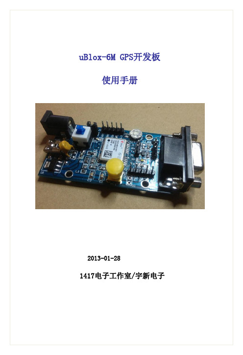
uBlox-GPS开发使用说明uBlox-6M GPS开发板使用手册2013-01-281417电子工作室/宇新电子版本更新说明版本修改日期修改说明V1.00 2012-12-28 初稿建立V2.00 2013-01-28 增加USB转串口接口、SPI接口前言A. 关于本手册本手册介绍了uBlox-6M开发板的硬件特性接口描述和连接使用方法。
同时对上位机软件的使用进行了详细的讲解。
如果用户需要了解更多的相关信息,请访问1417工作室论坛B. 版权声明本手册为开放手册,用户在保证手册内容完整性的前提下,可以自由转发C. 版本更新我们将会不定期对手册内容进行更新,更新说明会在手册的第2页中列出,请登录我们论坛中的“资料共享”专区,下载最新手册D. 意见反馈如果您发现手册中有不正确的地方,或者对手册内容更新有什么好的建议,请发送电子邮件至563216330@第一章产品说明1.1 产品简介1417工作室与宇新电子联合推出的uBlox系列产品uBlox-6M是一款高性价比的GPS开发板,为广大单片机、嵌入式和GPS爱好者提供一个高性能,稳定易用的GPS开发平台。
此开发板的GPS接收机采用世界顶级GPS厂商u-blox公司的NEO-6M模组,拥有世界先进的GPS 接收机技术。
开发板的硬件完全参照官方设计手册设计制作,经过长期测试和修改,最大限度地保证了接收信号的强度,使接收机的性能发挥到极限。
开发板接口简单,即插即用,可配合各种单片机和嵌入式开发板使用,同时配有上位机软件和参考代码1.2 功能特性高精度,高性能GPS接收机带有可充电后备电池,可实现热启动1秒钟快速定位TTL电平与CMOS电平的UART接口,方便连接各种处理器5V/1A DC直流电源输入1路RS232电平串口,1路USB2.0接口方便连接计算机,配有专业GPS测试软件电源和工作状态指示灯引出全部信号线,供开发测试使用1.3 应用领域汽车电子:民用车载GPS导航仪;物流车量追踪管理系统;车量防盗系统;城市智能交通管理系统等手持设备:智能手机,PDA,适用于个人旅游及野外探险的各种手持导航设备科学考查:地图测绘,水下地形测量,地质灾害监测工业农业:精细农业(无人耕种);工程机械控制;工程建筑测量;石油电力等行业对设施的管理和监测航空航海:飞机航路引导,船舶行驶导航1.4 GPS开发板配件清单名称数量说明uBlox-6M开发板1块NEO-6M主芯片GPS有源天线1块3米国产天线5V/1A直流电源1块给开发板提供电源交叉串口线1条用于连接计算机优质USB下载线1条用于连接计算机杜邦线4根用于连接其他开发板1.4.2 资料清单内容说明GPS测试程序(MCU)适用于51单片机的程序u-blox 手册u-blox原厂PDF手册GPS开发板用户手册开发板硬件介绍和使用说明GPS开发板原理图PDF格式原理图u-centerSetup-7.0.2.1 GPS测试评估软件,带USB驱动Google Earth 谷歌地球全球3D卫星地图导航软件PC版凯立德3D语音导航版串口调试助手V2.2 非常实用的串口工具1.5 GPS主芯片简介:(仅供参考)使用瑞士u-blox公司的 NEO-6M模组,第6代GPS接收机,搭载了高性能的50通道ublox 6技术,超过100万个有效相关器32通道采集引擎的处理能力使得模组可进行大规模并行搜索。

u-blox F9 HPS 1.30u-blox F9 high precision sensor fusion GNSS receiver Protocol version 33.30Interface descriptionAbstractThis document describes the interface (version 33.30) of the u-bloxF9 firmware HPS 1.30 platform.UBX-22010984 - R01C1-PublicDocument informationTitle u-blox F9 HPS 1.30Subtitle u-blox F9 high precision sensor fusion GNSS receiver Document type Interface descriptionDocument number UBX-22010984Revision and date R0116-Sep-2022 Disclosure restriction C1-Publicu-blox or third parties may hold intellectual property rights in the products, names, logos and designs included in this document. Copying, reproduction, or modification of this document or any part thereof is only permitted with the express written permission of u-blox. Disclosure to third parties is permitted for clearly public documents only.The information contained herein is provided "as is" and u-blox assumes no liability for its use. No warranty, either express or implied, is given, including but not limited to, with respect to the accuracy, correctness, reliability and fitness for a particular purpose of the information. This document may be revised by u-blox at any time without notice. For the most recent documents, visit .Copyright © 2022, u-blox AG.Contents1 General information (14)1.1 Document overview (14)1.2 Firmware and protocol versions (14)1.3 Receiver configuration (16)1.4 Message naming (17)1.5 GNSS, satellite, and signal identifiers (17)1.5.1 Overview (17)1.5.2 GNSS identifiers (18)1.5.3 Satellite identifiers (18)1.5.4 Signal identifiers (19)1.6 Message types (20)2 NMEA protocol (21)2.1 NMEA frame structure (21)2.2 NMEA protocol configuration (21)2.3 NMEA-proprietary messages (22)2.4 NMEA multi-GNSS operation (23)2.5 NMEA data fields (23)2.5.1 NMEA Talker ID (23)2.5.2 NMEA extra fields (23)2.5.3 NMEA latitude and longitude format (24)2.5.4 NMEA GNSS, satellite, and signal numbering (24)2.5.5 NMEA position fix flags (24)2.5.6 NMEA output of invalid or unknown data (25)2.6 NMEA messages overview (26)2.7 Standard messages (26)2.7.1 DTM (26)2.7.1.1 Datum reference (27)2.7.2 GAQ (27)2.7.2.1 Poll a standard message (Talker ID GA) (27)2.7.3 GBQ (28)2.7.3.1 Poll a standard message (Talker ID GB) (28)2.7.4 GBS (28)2.7.4.1 GNSS satellite fault detection (28)2.7.5 GGA (29)2.7.5.1 Global positioning system fix data (29)2.7.6 GLL (30)2.7.6.1 Latitude and longitude, with time of position fix and status (30)2.7.7 GLQ (30)2.7.7.1 Poll a standard message (Talker ID GL) (30)2.7.8 GNQ (31)2.7.8.1 Poll a standard message (Talker ID GN) (31)2.7.9 GNS (31)2.7.9.1 GNSS fix data (31)2.7.10 GPQ (32)2.7.10.1 Poll a standard message (Talker ID GP) (32)2.7.11 GQQ (32)2.7.11.1 Poll a standard message (Talker ID GQ) (33)2.7.12 GRS (33)2.7.12.1 GNSS range residuals (33)2.7.13 GSA (34)2.7.13.1 GNSS DOP and active satellites (34)2.7.14 GST (34)2.7.14.1 GNSS pseudorange error statistics (34)2.7.15 GSV (35)2.7.15.1 GNSS satellites in view (35)2.7.16 RLM (36)2.7.16.1 Return link message (RLM) (36)2.7.17 RMC (36)2.7.17.1 Recommended minimum data (36)2.7.18 THS (37)2.7.18.1 True heading and status (37)2.7.19 TXT (38)2.7.19.1 Text transmission (38)2.7.20 VTG (38)2.7.20.1 Course over ground and ground speed (38)2.7.21 ZDA (39)2.7.21.1 Time and date (39)2.8 Secondary output messages (40)2.8.1 GGA (40)2.8.1.1 Global positioning system fix data (40)2.8.2 GLL (41)2.8.2.1 Latitude and longitude, with time of position fix and status (41)2.8.3 GNS (41)2.8.3.1 GNSS fix data (42)2.8.4 GSA (43)2.8.4.1 GNSS DOP and active satellites (43)2.8.5 RMC (44)2.8.5.1 Recommended minimum data (44)2.8.6 VTG (45)2.8.6.1 Course over ground and ground speed (45)2.8.7 ZDA (45)2.8.7.1 Time and date (45)2.9 PUBX messages (46)2.9.1 CONFIG (PUBX,41) (46)2.9.1.1 Set protocols and baud rate (46)2.9.2 POSITION (PUBX,00) (47)2.9.2.1 Poll a PUBX,00 message (47)2.9.2.2 Lat/Long position data (47)2.9.3 RATE (PUBX,40) (48)2.9.3.1 Set NMEA message output rate (48)2.9.4 SVSTATUS (PUBX,03) (49)2.9.4.1 Poll a PUBX,03 message (49)2.9.5 TIME (PUBX,04) (49)2.9.5.1 Poll a PUBX,04 message (50)3 UBX protocol (51)3.1 UBX protocol key features (51)3.2 UBX frame structure (51)3.3 UBX payload definition rules (52)3.3.1 UBX structure packing (52)3.3.2 UBX reserved elements (52)3.3.3 UBX undefined values (52)3.3.4 UBX conditional values (52)3.3.5 UBX data types (52)3.3.6 UBX fields scale and unit (53)3.3.7 UBX repeated fields (53)3.3.8 UBX payload decoding (54)3.4 UBX checksum (54)3.5 UBX message flow (54)3.5.1 UBX acknowledgement (54)3.5.2 UBX polling mechanism (54)3.6 GNSS, satellite, and signal numbering (55)3.7 UBX message example (55)3.8 UBX messages overview (56)3.9 UBX-ACK (0x05) (59)3.9.1 UBX-ACK-ACK (0x05 0x01) (59)3.9.1.1 Message acknowledged (60)3.9.2 UBX-ACK-NAK (0x05 0x00) (60)3.9.2.1 Message not acknowledged (60)3.10 UBX-CFG (0x06) (60)3.10.1 UBX-CFG-CFG (0x06 0x09) (60)3.10.1.1 Clear, save and load configurations (60)3.10.2 UBX-CFG-RST (0x06 0x04) (61)3.10.2.1 Reset receiver / Clear backup data structures (61)3.10.3 UBX-CFG-SPT (0x06 0x64) (62)3.10.3.1 Configure and start a sensor production test (62)3.10.4 UBX-CFG-VALDEL (0x06 0x8c) (63)3.10.4.1 Delete configuration item values (63)3.10.4.2 Delete configuration item values (with transaction) (63)3.10.5 UBX-CFG-VALGET (0x06 0x8b) (64)3.10.5.1 Get configuration items (65)3.10.5.2 Configuration items (65)3.10.6 UBX-CFG-VALSET (0x06 0x8a) (66)3.10.6.1 Set configuration item values (66)3.10.6.2 Set configuration item values (with transaction) (67)3.11 UBX-ESF (0x10) (68)3.11.1 UBX-ESF-ALG (0x10 0x14) (68)3.11.1.1 IMU alignment information (68)3.11.2 UBX-ESF-INS (0x10 0x15) (69)3.11.2.1 Vehicle dynamics information (69)3.11.3 UBX-ESF-MEAS (0x10 0x02) (70)3.11.3.1 External sensor fusion measurements (70)3.11.4 UBX-ESF-RAW (0x10 0x03) (70)3.11.4.1 Raw sensor measurements (70)3.11.5 UBX-ESF-STATUS (0x10 0x10) (71)3.11.5.1 External sensor fusion status (71)3.12 UBX-INF (0x04) (72)3.12.1 UBX-INF-DEBUG (0x04 0x04) (72)3.12.1.1 ASCII output with debug contents (72)3.12.2 UBX-INF-ERROR (0x04 0x00) (73)3.12.2.1 ASCII output with error contents (73)3.12.3 UBX-INF-NOTICE (0x04 0x02) (73)3.12.3.1 ASCII output with informational contents (73)3.12.4 UBX-INF-TEST (0x04 0x03) (73)3.12.4.1 ASCII output with test contents (73)3.12.5 UBX-INF-WARNING (0x04 0x01) (74)3.12.5.1 ASCII output with warning contents (74)3.13 UBX-MGA (0x13) (74)3.13.1 UBX-MGA-ACK (0x13 0x60) (74)3.13.1.1 Multiple GNSS acknowledge message (74)3.13.2 UBX-MGA-BDS (0x13 0x03) (75)3.13.2.1 BeiDou ephemeris assistance (75)3.13.2.2 BeiDou almanac assistance (76)3.13.2.3 BeiDou health assistance (77)3.13.2.4 BeiDou UTC assistance (77)3.13.2.5 BeiDou ionosphere assistance (78)3.13.3 UBX-MGA-DBD (0x13 0x80) (78)3.13.3.1 Poll the navigation database (78)3.13.3.2 Navigation database dump entry (79)3.13.4 UBX-MGA-GAL (0x13 0x02) (79)3.13.4.1 Galileo ephemeris assistance (79)3.13.4.2 Galileo almanac assistance (80)3.13.4.3 Galileo GPS time offset assistance (81)3.13.4.4 Galileo UTC assistance (82)3.13.5 UBX-MGA-GLO (0x13 0x06) (82)3.13.5.1 GLONASS ephemeris assistance (82)3.13.5.2 GLONASS almanac assistance (83)3.13.5.3 GLONASS auxiliary time offset assistance (84)3.13.6 UBX-MGA-GPS (0x13 0x00) (84)3.13.6.1 GPS ephemeris assistance (84)3.13.6.2 GPS almanac assistance (86)3.13.6.3 GPS health assistance (86)3.13.6.4 GPS UTC assistance (87)3.13.6.5 GPS ionosphere assistance (87)3.13.7 UBX-MGA-INI (0x13 0x40) (88)3.13.7.1 Initial position assistance (88)3.13.7.2 Initial position assistance (88)3.13.7.3 Initial time assistance (89)3.13.7.4 Initial time assistance (90)3.13.7.5 Initial clock drift assistance (91)3.13.7.6 Initial frequency assistance (91)3.13.8 UBX-MGA-QZSS (0x13 0x05) (91)3.13.8.1 QZSS ephemeris assistance (92)3.13.8.2 QZSS almanac assistance (93)3.13.8.3 QZSS health assistance (93)3.13.9 UBX-MGA-SF (0x13 0x10) (94)3.13.9.1 Sensor fusion initialization data (94)3.13.9.2 Sensor fusion initialization data (94)3.14 UBX-MON (0x0a) (95)3.14.1 UBX-MON-COMMS (0x0a 0x36) (95)3.14.1.1 Communication port information (95)3.14.2 UBX-MON-GNSS (0x0a 0x28) (96)3.14.2.1 Information message major GNSS selection (96)3.14.3 UBX-MON-HW (0x0a 0x09) (96)3.14.3.1 Hardware status (97)3.14.4 UBX-MON-HW2 (0x0a 0x0b) (97)3.14.4.1 Extended hardware status (98)3.14.5 UBX-MON-HW3 (0x0a 0x37) (98)3.14.5.1 I/O pin status (98)3.14.6 UBX-MON-IO (0x0a 0x02) (99)3.14.6.1 I/O system status (99)3.14.7 UBX-MON-MSGPP (0x0a 0x06) (100)3.14.7.1 Message parse and process status (100)3.14.8 UBX-MON-PATCH (0x0a 0x27) (100)3.14.8.1 Installed patches (100)3.14.9 UBX-MON-RF (0x0a 0x38) (101)3.14.9.1 RF information (101)3.14.10 UBX-MON-RXBUF (0x0a 0x07) (102)3.14.10.1 Receiver buffer status (102)3.14.11 UBX-MON-RXR (0x0a 0x21) (102)3.14.11.1 Receiver status information (102)3.14.12 UBX-MON-SPAN (0x0a 0x31) (102)3.14.12.1 Signal characteristics (103)3.14.13 UBX-MON-SPT (0x0a 0x2f) (103)3.14.13.1 Sensor production test (103)3.14.14 UBX-MON-SYS (0x0a 0x39) (105)3.14.14.1 Current system performance information (105)3.14.15 UBX-MON-TXBUF (0x0a 0x08) (106)3.14.15.1 Transmitter buffer status (106)3.14.16 UBX-MON-VER (0x0a 0x04) (107)3.14.16.1 Receiver and software version (107)3.15 UBX-NAV (0x01) (107)3.15.1 UBX-NAV-ATT (0x01 0x05) (108)3.15.1.1 Attitude solution (108)3.15.2 UBX-NAV-CLOCK (0x01 0x22) (108)3.15.2.1 Clock solution (108)3.15.3 UBX-NAV-COV (0x01 0x36) (109)3.15.3.1 Covariance matrices (109)3.15.4 UBX-NAV-DOP (0x01 0x04) (109)3.15.4.1 Dilution of precision (109)3.15.5 UBX-NAV-EELL (0x01 0x3d) (110)3.15.5.1 Position error ellipse parameters (110)3.15.6 UBX-NAV-EOE (0x01 0x61) (110)3.15.6.1 End of epoch (110)3.15.7 UBX-NAV-GEOFENCE (0x01 0x39) (111)3.15.7.1 Geofencing status (111)3.15.8 UBX-NAV-HPPOSECEF (0x01 0x13) (111)3.15.8.1 High precision position solution in ECEF (111)3.15.9 UBX-NAV-HPPOSLLH (0x01 0x14) (112)3.15.9.1 High precision geodetic position solution (112)3.15.10 UBX-NAV-ORB (0x01 0x34) (113)3.15.10.1 GNSS orbit database info (113)3.15.11 UBX-NAV-PL (0x01 0x62) (114)3.15.11.1 Protection level information (114)3.15.12 UBX-NAV-POSECEF (0x01 0x01) (116)3.15.12.1 Position solution in ECEF (116)3.15.13 UBX-NAV-POSLLH (0x01 0x02) (116)3.15.13.1 Geodetic position solution (117)3.15.14 UBX-NAV-PVAT (0x01 0x17) (117)3.15.14.1 Navigation position velocity attitude time solution (117)3.15.15 UBX-NAV-PVT (0x01 0x07) (119)3.15.15.1 Navigation position velocity time solution (119)3.15.16 UBX-NAV-RELPOSNED (0x01 0x3c) (121)3.15.16.1 Relative positioning information in NED frame (122)3.15.17 UBX-NAV-SAT (0x01 0x35) (123)3.15.17.1 Satellite information (123)3.15.18 UBX-NAV-SBAS (0x01 0x32) (125)3.15.18.1 SBAS status data (125)3.15.19 UBX-NAV-SIG (0x01 0x43) (126)3.15.19.1 Signal information (126)3.15.20 UBX-NAV-SLAS (0x01 0x42) (127)3.15.20.1 QZSS L1S SLAS status data (127)3.15.21 UBX-NAV-STATUS (0x01 0x03) (128)3.15.21.1 Receiver navigation status (128)3.15.22 UBX-NAV-TIMEBDS (0x01 0x24) (130)3.15.22.1 BeiDou time solution (130)3.15.23 UBX-NAV-TIMEGAL (0x01 0x25) (130)3.15.23.1 Galileo time solution (130)3.15.24 UBX-NAV-TIMEGLO (0x01 0x23) (131)3.15.24.1 GLONASS time solution (131)3.15.25 UBX-NAV-TIMEGPS (0x01 0x20) (132)3.15.25.1 GPS time solution (132)3.15.26 UBX-NAV-TIMELS (0x01 0x26) (132)3.15.26.1 Leap second event information (132)3.15.27 UBX-NAV-TIMEQZSS (0x01 0x27) (133)3.15.27.1 QZSS time solution (134)3.15.28 UBX-NAV-TIMEUTC (0x01 0x21) (134)3.15.28.1 UTC time solution (134)3.15.29 UBX-NAV-VELECEF (0x01 0x11) (135)3.15.29.1 Velocity solution in ECEF (135)3.15.30 UBX-NAV-VELNED (0x01 0x12) (135)3.15.30.1 Velocity solution in NED frame (136)3.16 UBX-NAV2 (0x29) (136)3.16.1 UBX-NAV2-CLOCK (0x29 0x22) (136)3.16.1.1 Clock solution (136)3.16.2 UBX-NAV2-COV (0x29 0x36) (137)3.16.2.1 Covariance matrices (137)3.16.3 UBX-NAV2-DOP (0x29 0x04) (137)3.16.3.1 Dilution of precision (137)3.16.4 UBX-NAV2-EELL (0x29 0x3d) (138)3.16.4.1 Position error ellipse parameters (138)3.16.5 UBX-NAV2-EOE (0x29 0x61) (138)3.16.5.1 End of epoch (138)3.16.6 UBX-NAV2-POSECEF (0x29 0x01) (139)3.16.6.1 Position solution in ECEF (139)3.16.7 UBX-NAV2-POSLLH (0x29 0x02) (139)3.16.7.1 Geodetic position solution (139)3.16.8 UBX-NAV2-PVAT (0x29 0x17) (140)3.16.8.1 Navigation position velocity attitude time solution (140)3.16.9 UBX-NAV2-PVT (0x29 0x07) (142)3.16.9.1 Navigation position velocity time solution (142)3.16.10 UBX-NAV2-SAT (0x29 0x35) (144)3.16.10.1 Satellite information (144)3.16.11 UBX-NAV2-SBAS (0x29 0x32) (146)3.16.11.1 SBAS status data (146)3.16.12 UBX-NAV2-SIG (0x29 0x43) (147)3.16.12.1 Signal information (147)3.16.13 UBX-NAV2-SLAS (0x29 0x42) (148)3.16.13.1 QZSS L1S SLAS status data (148)3.16.14 UBX-NAV2-STATUS (0x29 0x03) (149)3.16.14.1 Receiver navigation status (149)3.16.15 UBX-NAV2-TIMEBDS (0x29 0x24) (151)3.16.15.1 BeiDou time solution (151)3.16.16 UBX-NAV2-TIMEGAL (0x29 0x25) (151)3.16.16.1 Galileo time solution (151)3.16.17 UBX-NAV2-TIMEGLO (0x29 0x23) (152)3.16.17.1 GLONASS time solution (152)3.16.18 UBX-NAV2-TIMEGPS (0x29 0x20) (153)3.16.18.1 GPS time solution (153)3.16.19 UBX-NAV2-TIMELS (0x29 0x26) (153)3.16.19.1 Leap second event information (153)3.16.20 UBX-NAV2-TIMEQZSS (0x29 0x27) (154)3.16.20.1 QZSS time solution (155)3.16.21 UBX-NAV2-TIMEUTC (0x29 0x21) (155)3.16.21.1 UTC time solution (155)3.16.22 UBX-NAV2-VELECEF (0x29 0x11) (156)3.16.22.1 Velocity solution in ECEF (156)3.16.23 UBX-NAV2-VELNED (0x29 0x12) (156)3.16.23.1 Velocity solution in NED frame (157)3.17 UBX-RXM (0x02) (157)3.17.1 UBX-RXM-COR (0x02 0x34) (157)3.17.1.1 Differential correction input status (157)3.17.2 UBX-RXM-MEASX (0x02 0x14) (158)3.17.2.1 Satellite measurements for RRLP (158)3.17.3 UBX-RXM-PMP (0x02 0x72) (160)3.17.3.1 PMP (LBAND) message (160)3.17.4 UBX-RXM-PMREQ (0x02 0x41) (160)3.17.4.1 Power management request (160)3.17.4.2 Power management request (161)3.17.5 UBX-RXM-QZSSL6 (0x02 0x73) (161)3.17.5.1 QZSS L6 message (161)3.17.6 UBX-RXM-RAWX (0x02 0x15) (162)3.17.6.1 Multi-GNSS raw measurements (162)3.17.7 UBX-RXM-RLM (0x02 0x59) (164)3.17.7.1 Galileo SAR short-RLM report (164)3.17.7.2 Galileo SAR long-RLM report (164)3.17.8 UBX-RXM-RTCM (0x02 0x32) (165)3.17.8.1 RTCM input status (165)3.17.9 UBX-RXM-SPARTN (0x02 0x33) (165)3.17.9.1 SPARTN input status (165)3.17.10 UBX-RXM-SPARTNKEY (0x02 0x36) (166)3.17.10.1 Poll installed keys (166)3.17.10.2 Transfer dynamic SPARTN keys (166)3.18 UBX-SEC (0x27) (167)3.18.1 UBX-SEC-SIG (0x27 0x09) (167)3.18.1.1 Signal security information (167)3.18.2 UBX-SEC-SIGLOG (0x27 0x10) (168)3.18.2.1 Signal security log (168)3.18.3 UBX-SEC-UNIQID (0x27 0x03) (168)3.18.3.1 Unique chip ID (169)3.19 UBX-TIM (0x0d) (169)3.19.1 UBX-TIM-TM2 (0x0d 0x03) (169)3.19.1.1 Time mark data (169)3.19.2 UBX-TIM-TP (0x0d 0x01) (170)3.19.2.1 Time pulse time data (170)3.19.3 UBX-TIM-VRFY (0x0d 0x06) (171)3.19.3.1 Sourced time verification (171)3.20 UBX-UPD (0x09) (171)3.20.1 UBX-UPD-SOS (0x09 0x14) (171)3.20.1.1 Poll backup restore status (172)3.20.1.2 Create backup in flash (172)3.20.1.3 Clear backup in flash (172)3.20.1.4 Backup creation acknowledge (172)3.20.1.5 System restored from backup (173)4 RTCM protocol (174)4.1 RTCM introduction (174)4.2 RTCM 3.x configuration (174)4.3 RTCM messages overview (174)4.4 RTCM 3.3 messages (175)4.4.1 Message type 1001 (175)4.4.1.1 L1-only GPS RTK observables (175)4.4.2 Message type 1002 (176)4.4.2.1 Extended L1-only GPS RTK observables (176)4.4.3 Message type 1003 (176)4.4.3.1 L1/L2 GPS RTK observables (176)4.4.4 Message type 1004 (177)4.4.4.1 Extended L1/L2 GPS RTK observables (177)4.4.5 Message type 1005 (177)4.4.5.1 Stationary RTK reference station ARP (177)4.4.6 Message type 1006 (178)4.4.6.1 Stationary RTK reference station ARP with antenna height (178)4.4.7 Message type 1007 (178)4.4.7.1 Antenna descriptor (179)4.4.8 Message type 1009 (179)4.4.8.1 L1-only GLONASS RTK observables (179)4.4.9 Message type 1010 (180)4.4.9.1 Extended L1-Only GLONASS RTK observables (180)4.4.10 Message type 1011 (180)4.4.10.1 L1&L2 GLONASS RTK observables (180)4.4.11 Message type 1012 (181)4.4.11.1 Extended L1&L2 GLONASS RTK observables (181)4.4.12 Message type 1033 (181)4.4.12.1 Receiver and antenna descriptors (181)4.4.13 Message type 1074 (182)4.4.13.1 GPS MSM4 (182)4.4.14 Message type 1075 (182)4.4.14.1 GPS MSM5 (182)4.4.15 Message type 1077 (183)4.4.15.1 GPS MSM7 (183)4.4.16 Message type 1084 (184)4.4.16.1 GLONASS MSM4 (184)4.4.17 Message type 1085 (184)4.4.17.1 GLONASS MSM5 (184)4.4.18 Message type 1087 (185)4.4.18.1 GLONASS MSM7 (185)4.4.19 Message type 1094 (185)4.4.19.1 Galileo MSM4 (185)4.4.20 Message type 1095 (186)4.4.20.1 Galileo MSM5 (186)4.4.21 Message type 1097 (186)4.4.21.1 Galileo MSM7 (187)4.4.22 Message type 1124 (187)4.4.22.1 BeiDou MSM4 (187)4.4.23 Message type 1125 (188)4.4.23.1 BeiDou MSM5 (188)4.4.24 Message type 1127 (188)4.4.24.1 BeiDou MSM7 (188)4.4.25 Message type 1230 (189)4.4.25.1 GLONASS L1 and L2 code-phase biases (189)5 SPARTN protocol (190)5.1 SPARTN introduction (190)5.2 SPARTN configuration (190)5.3 SPARTN messages overview (190)5.4 SPARTN messages (191)5.4.1 Message type 0, sub-type 0 (191)5.4.1.1 GPS orbit, clock, bias (OCB) (191)5.4.2 Message type 0, sub-type 1 (191)5.4.2.1 GLONASS orbit, clock, bias (OCB) (192)5.4.3 Message type 0, sub-type 2 (192)5.4.3.1 Galileo orbit, clock, bias (OCB) (192)5.4.4 Message type 0, sub-type 3 (193)5.4.4.1 BeiDou orbit, clock, bias (OCB) (193)5.4.5 Message type 0, sub-type 4 (194)5.4.5.1 QZSS orbit, clock, bias (OCB) (194)5.4.6 Message type 1, sub-type 0 (195)5.4.6.1 GPS high-precision atmosphere correction (HPAC) (195)5.4.7 Message type 1, sub-type 1 (195)5.4.7.1 GLONASS high-precision atmosphere correction (HPAC) (195)5.4.8 Message type 1, sub-type 2 (196)5.4.8.1 Galileo high-precision atmosphere correction (HPAC) (196)5.4.9 Message type 1, sub-type 3 (197)5.4.9.1 BeiDou high-precision atmosphere correction (HPAC) (197)5.4.10 Message type 1, sub-type 4 (198)5.4.10.1 QZSS high-precision atmosphere correction (HPAC) (198)5.4.11 Message type 2, sub-type 0 (199)5.4.11.1 Geographic area definition (GAD) (199)5.4.12 Message type 3, sub-type 0 (199)5.4.12.1 Basic-precision atmosphere correction (BPAC) (199)6 Configuration interface (201)6.1 Configuration database (201)6.2 Configuration items (201)6.3 Configuration layers (202)6.4 Configuration interface access (203)6.4.1 UBX protocol interface (203)6.5 Configuration data (203)6.6 Configuration transactions (204)6.7 Configuration reset behavior (205)6.8 Configuration overview (205)6.9 Configuration reference (206)6.9.1 CFG-BDS: BeiDou system configuration (206)6.9.2 CFG-GEOFENCE: Geofencing configuration (206)6.9.3 CFG-HW: Hardware configuration (207)6.9.4 CFG-I2C: Configuration of the I2C interface (209)6.9.5 CFG-I2CINPROT: Input protocol configuration of the I2C interface (209)6.9.6 CFG-I2COUTPROT: Output protocol configuration of the I2C interface (209)6.9.7 CFG-INFMSG: Information message configuration (209)6.9.8 CFG-MOT: Motion detector configuration (210)6.9.9 CFG-MSGOUT: Message output configuration (211)6.9.10 CFG-NAV2: Secondary output configuration (231)6.9.11 CFG-NAVHPG: High precision navigation configuration (231)6.9.12 CFG-NAVSPG: Standard precision navigation configuration (232)6.9.13 CFG-NMEA: NMEA protocol configuration (236)6.9.14 CFG-QZSS: QZSS system configuration (238)6.9.15 CFG-RATE: Navigation and measurement rate configuration (238)6.9.16 CFG-RINV: Remote inventory (239)6.9.17 CFG-RTCM: RTCM protocol configuration (239)6.9.18 CFG-SBAS: SBAS configuration (240)6.9.19 CFG-SEC: Security configuration (241)6.9.20 CFG-SFCORE: Sensor fusion (SF) core configuration (242)6.9.21 CFG-SFIMU: Sensor fusion (SF) inertial measurement unit (IMU) configuration (242)6.9.22 CFG-SFODO: Sensor fusion (SF) odometer configuration (243)6.9.23 CFG-SIGNAL: Satellite systems (GNSS) signal configuration (244)6.9.24 CFG-SPARTN: SPARTN configuration (245)6.9.25 CFG-SPI: Configuration of the SPI interface (245)6.9.26 CFG-SPIINPROT: Input protocol configuration of the SPI interface (246)6.9.27 CFG-SPIOUTPROT: Output protocol configuration of the SPI interface (246)6.9.28 CFG-TP: Time pulse configuration (246)6.9.29 CFG-TXREADY: TX ready configuration (248)6.9.30 CFG-UART1: Configuration of the UART1 interface (248)6.9.31 CFG-UART1INPROT: Input protocol configuration of the UART1 interface (249)6.9.32 CFG-UART1OUTPROT: Output protocol configuration of the UART1 interface (249)6.9.33 CFG-UART2: Configuration of the UART2 interface (250)6.9.34 CFG-UART2INPROT: Input protocol configuration of the UART2 interface (250)6.9.35 CFG-UART2OUTPROT: Output protocol configuration of the UART2 interface (251)6.9.36 CFG-USB: Configuration of the USB interface (251)6.9.37 CFG-USBINPROT: Input protocol configuration of the USB interface (251)6.9.38 CFG-USBOUTPROT: Output protocol configuration of the USB interface (252)6.10 Legacy UBX message fields reference (252)Configuration defaults (258)Related documents (281)Revision history (282)1 General information1.1 Document overviewThis document describes the interface of the u-blox F9 high precision sensor fusion GNSS receiver. The interface consists of the following parts:•NMEA protocol•UBX protocol•RTCM protocol•SPARTN protocol•Configuration interfaceSome of the features described here may not be available in the receiver, and some mayrequire specific configurations to be enabled. See the applicable data sheet for availability of the features and the integration manual for instructions for enabling them.Previous versions of u-blox receiver documentation combined general receiver description and interface specification. In the current documentation the receiver description isincluded in the integration manual.See also Related documents.1.2 Firmware and protocol versionsu-blox generation 9 receivers execute firmware from internal ROM or from internal code-RAM. If the firmware image is stored in a flash it is loaded into the code-RAM before execution. It is also possible to store the firmware image in the host system. The firmware is then loaded into the code-RAM from the host processor. (Loading the firmware from the host processor is not supported in all products.) If there is no external firmware image, then the firmware is executed from the ROM.The location and the version of the boot loader and the currently running firmware can be found in the boot screen and in the UBX-MON-VER message. If the firmware has been loaded from a connected flash or from the host processor, it is indicated by text "EXT". When the receiver is started, the boot screen is output automatically in UBX-INF-NOTICE or NMEA-Standard-TXT messages if configured using CFG-INFMSG. The UBX-MON-VER message can be polled using the UBX polling mechanism.The following u-center screenshots show an example of a u-blox receiver running firmware loaded from flash:The following information is available (✓) from the boot screen (B) and the UBX-MON-VER message (M):B M Example Information✓u-blox AG - Start of the boot screen.✓HW UBX 9 00190000Hardware version of the u-blox receiver.✓00190000✓✓EXT CORE 1.00 (61b2dd)Base (CORE) firmware version and revision number, loaded from externalmemory (EXT).EXT LAP 1.00 (12a3bc)Product firmware version and revision number, loaded from external memory(EXT). Available only in some firmware versions. See below for a list of productacronyms.✓✓ROM BASE 0x118B2060Revision number of the underlying boot loader firmware in ROM.✓✓FWVER=HPG 1.12Product firmware version number, where:•SPG = Standard precision GNSS product•HPG = High precision GNSS product•ADR = Automotive dead reckoning product•TIM = Time sync product•LAP = Lane accurate positioning product•HPS = High precision sensor fusion product•DBS = Dual band standard precision•MDR = Multi-mode dead reckoning product•PMP = L-Band Inmarsat point-to-multipoint receiver•QZS = QZSS L6 centimeter level augmentation service (CLAS) messagereceiver•DBD = Dual band dead reckoning product•LDR = ROM bootloader, no GNSS functionality✓✓PROTVER=34.00Supported protocol version.✓✓MOD=ZED-F9P Module name (if available).✓✓GPS;GLO;GAL;BDS List of supported major GNSS (see GNSS identifiers).✓✓SBAS;QZSS List of supported augmentation systems (see GNSS identifiers).B M Example Information✓ANTSUPERV=AC SD PDoS SR Configuration of the antenna supervisor (if available), where:•AC = Active antenna control enabled•SD = Short circuit detection enabled•OD = Open circuit detection enabled•PDoS = Short circuit power down logic enabled•SR = Automatic recovery from short state enabled✓PF=FFF79Product configuration.✓BD=E01C GNSS band configuration.The "FWVER" product firmware version indicates which firmware is currently running. This is referred to as "firmware version" in this and other documents.The revision numbers should only be used to identify a known firmware version. They arenot necessarily numeric nor are they guaranteed to increase with newer firmware versions.Similarly, firmware version numbers can have additional non-numeric informationappended, such as in "5.00B03".Not every entry is output by all u-blox receivers. The availability of some of the information depends on the product, the firmware location and the firmware version.The product firmware version and the base firmware version relate to the protocol version:Product firmware version Base firmware version Protocol versionHPS 1.00EXT CORE 1.00 (500086)33.00HPS 1.20EXT CORE 1.00 (a669b8)33.20HPS 1.21EXT CORE 1.00 (e2b374)33.21HPS 1.30EXT CORE 1.00 (a59682)33.301.3 Receiver configurationu-blox positioning receivers are fully configurable with UBX protocol messages. The configuration used by the receiver during normal operation is called the "current configuration". The current configuration can be changed during normal operation by sending UBX-CFG-VALSET messages over any I/O port. The receiver will change its current configuration immediately after receiving a configuration message. The receiver will always use the current configuration only.The current configuration is loaded from permanent configuration hard-coded in the receiver firmware (the defaults) and from non-volatile memory (user configuration) on startup of the receiver. Changes made to the current configuration at run-time will be lost when there is a power cycle, a hardware reset or a (complete) controlled software reset (see Configuration reset behavior).See Configuration interface for a detailed description of the receiver configuration system, the explanation of the configuration concept and its principles and interfaces.The configuration interface has changed from earlier u-blox positioning receivers. Thereis some backwards compatibility provided in UBX-CFG configuration messages. Users are strongly advised to only use the Configuration interface. See also Legacy UBX messagefields reference.See the integration manual for a basic receiver configuration most commonly used.。

u-center2 用法
u-center2是u-blox公司开发的一款专为u-blox GNSS接收器设计的软件工具,主要用于配置和监控接收器的工作状态以及进行位置解算。
u-center2的主要用法包括:
1. 连接接收器:在u-center2中,可以通过串口、USB或者无
线方式与GNSS接收器进行连接。
连接成功后,u-center2将显示接收器的详细信息,包括型号、固件版本等。
2. 配置接收器:通过u-center2,可以配置接收器的工作模式、输出数据格式、波特率等参数。
可以根据具体需求,自定义接收器的工作方式。
3. 监控接收器状态:u-center2提供了丰富的状态监控功能,可以实时显示接收器的信号质量、卫星信号图、接收器的位置解算精度等信息。
可以通过这些信息,评估接收器的工作状况。
4. 数据记录和回放:u-center2支持将接收器接收到的原始数据进行记录和回放。
可以用于故障排查、性能评估等。
5. 卫星信号分析:u-center2提供了卫星信号分析工具,可以实时显示接收器所接收到的卫星信号质量。
可以用于选择合适的卫星以提高接收器的定位性能。
以上只是u-center2的一些常用用法,其功能非常丰富。
用户
可以根据具体需求,灵活使用u-center2来设置、监控和优化GNSS接收器的工作。
uBlox-6M GPS开发板使用手册2013-01-281417电子工作室/宇新电子最大更新速率:<4Hz灵敏度:冷启动 -144dBm跟踪灵敏度 -160dBm捕获灵敏度 -160dBm 定位精度: Auto < 2.5mSBAS < 2m定时精度: RMS 30ns99% <60ns极限速度: 500m/s运行温度: -40~85℃封装尺寸: 16 × 12.2 × 2.4 mm1.5.3电气性能:工作电压: 2.7V~3.6V功耗:全速模式**********ECO 模式**********备用电池: 1.4V~3.6V,25uA1.5.4接口协议:串行接口: 1 UART1 USB V2.0 全速12Mbit/s1 IIC1 SPI其他接口: 1 时间脉冲输出1 外部中断输入协议: NMEA,UBX二进制1.5.5 芯片引脚引脚定义:沟通无止境 合作有乾坤 8 / 37 技术热线QQ :563216330第二章 开发板硬件介绍2.1 实物图2.2 结构布局开发板尺寸:35*65mm天线SMA 座电源开关电源指示灯5V 转3.3V 芯片 1117I2C 接口 USB 接口80mA 自恢复 保险 DC5V 插座 USB 选择 MS621充电电池uBlox-6M 装配孔PPS 指示灯 DB9 孔座: RS232 主要接计算机或单片开发板CMOS 串口接口,譬如:ARM 2440TTL 串口 接口 5V 的单片机 SPI 接口 TX 指示灯 RX 指示灯2.3 接口说明2.3.1 接口说明表标号名称说明1NEO-6M主芯片NEO-6M主芯片2电源输入DC5V输入2.3.2 I/O接口表第三章上位机软件使用说明3.1 连接方式沟通无止境合作有乾坤9 / 37技术热线QQ:5632163303.2 使用串口调试助手1.打开光盘中的串口调试助手软件(uartassist.exe),根据自己电脑的实际串口选择串口号,默认的是COM1(我电脑的串口号是COM4)波特率:9600校验位:NONE数据位:8停止位:1设置好串口属性后,点击“打开”按钮,打开串口。
测试u-blox LEON-G100芯片SMTP功能流程1. 设置错误信息格式。
AT+CMEE=2↙ 1为错误编码,2为详细。
2.设置PIN码。
如果设置不使用PIN码,芯片会自动注册GSM和GPRS网络,注册所需时间至少25秒(以信号情况);如果设置使用PIN码,也至少需要25秒时间进行注册,同时需要发送以下AT命令:AT+CPIN?↙检查PIN码功能状态,可以省略。
+CPIN: SIM PINOK 说明还未验证,需进行PIN码验证。
AT+CPIN="1234"↙发送需验证的PIN码,引号内为芯片所对应的PIN码,可以在m-center中设置。
AT+CPIN?↙检查PIN码功能状态,可以省略。
+CPIN: READYOK 已通过PIN码验证或无需验证PIN码。
3.检查GSM和GPRS注册状态。
AT+COPS?↙查看GSM网络注册情况。
+COPS: 0,0,"China Mobile"OK 返回GSM网络的注册状态。
AT+CGATT?↙检查GPRS连接状态。
+CGATT: 1OK 返回结果。
AT+CGREG=1↙设置GPRS状态提示,当失去连接后会发送提示+CGREG:1,0。
AT+CREG=1↙设置GSM状态提示,当失去连接时会发送提示+CREG:1,0。
4.设置APN,获取动态IP。
AT+UPSD=0,1,"CMNET"↙设置你的APN运营商。
OKAT+UPSD=0,7,"0.0.0.0"↙获取动态IP地址。
OKAT+UPSDA=0,1↙将GPRS设置存入非易失内存。
OKAT+UPSDA=0,3↙激活GPRS连接,需要等待至少5秒。
OKAT+UPSND=0,0↙检查所获取的IP地址。
+UPSND: 0,0,"10.60.194.177"OK 返回所获取到的IP地址。
5.设置Smtp服务器连接参数。
Ublox系列芯片之NEO-6M使用小技巧相信好多电子工程师用过GPS模块,其中Ublox系列芯片是一类淘宝网上见得较多主控芯片,我用过的是NEO-6M主控。
该芯片对外有4个接口:UART,SPI,USB,I2C。
可向用户传回GSV, RMC,GSA,GGA,GLL,VTG等数据,但对于一些用户可能只用到其中一类或部分数据,不会用到所有的数据,这时接收所有的数据就可能对用户造成麻烦。
我们可以过U-center软件关闭不用的接口,应该会对低功耗有所帮助,也可以用该软件关闭不必要的数据,这样我们会很方便地处理数据。
但只要我们对主控芯片断电,所有的工作全部白做,设置又恢复到初始化的状态,所有的接口、数据又被打开了。
后来,我通过某种手段——串口监视找出了有效方法,下面跟大家分享一下:以下命令可打开或关闭对应数据,接口只留下UART,其它接口全部关闭,若用户想用其它接口,以下的命令是不适合的。
gga(off) B5 62 06 01 08 00 F0 00 00 00 00 00 00 01 00 24gga(1on) B5 62 06 01 08 00 F0 00 00 01 00 00 00 01 01 29gll(off) B5 62 06 01 08 00 F0 01 00 00 00 00 00 01 01 2Bgll(1on) B5 62 06 01 08 00 F0 01 00 01 00 00 00 01 02 30gsa(off) B5 62 06 01 08 00 F0 02 00 00 00 00 00 01 02 32gsa(1on) B5 62 06 01 08 00 F0 02 00 01 00 00 00 01 03 37gsv(off) B5 62 06 01 08 00 F0 03 00 00 00 00 00 01 03 39gsv(1on) B5 62 06 01 08 00 F0 03 00 01 00 00 00 01 04 3Ermc(off) B5 62 06 01 08 00 F0 04 00 00 00 00 00 01 04 40rmc(1on) B5 62 06 01 08 00 F0 04 00 01 00 00 00 01 05 45vtg(off) B5 62 06 01 08 00 F0 05 00 00 00 00 00 01 05 47vtg(1on) B5 62 06 01 08 00 F0 05 00 01 00 00 00 01 06 4C以上命令off为关闭相应数据,on为打开相应数据。
TEL : (03)462-6569 (桃園-總公司) / (04)2261-0357 (台中) / (06)208-6651 (台南)●BreadboardsSolid Aluminum Breadboard ............................ Honeycomb Optical Breadboard ......................●Benchtop Isolation Systems ..........................●Optical TablesWorkstations .................................................... Table System ................................................... Customized Workstations ................................●Optical RailsMiniature Series ............................................... Optical Bench / Rail / Carrier ............................●Bases / ClampsPost Adaptor .................................................... Base Clamps / Slide Bases ..............................●Posts / HoldersHolding Fork / Pedestal .................................... Miniature Series ...............................................12.7mm/12mm Posts / Holders ...................... Isolated Series .................................................●Optical MountsMirrors Mounts ................................................ Prism Mounts .................................................. Polarizer Mounts .............................................. Lens Holders .................................................... Filter Holders ................................................... Cylindrical Mounts ...........................................●Tilt PlatformsSingle Axis Tilt Platforms ................................ Multi-Axis Tilt Platforms . (3)4791524272935374349525559848894111119127131136168172175185188193206210216220226229230246251253254257258264267269●Manual StagesLinear Translation Stage ...................................Dovetail Linear Stage ........................................Large Platform Stage ........................................Rotation Stage ..................................................Jack ..................................................................●Goniometers ....................................................●Multi-Axis Stages ...........................................●Angle Brackets / Adaptor Platforms ..........●Fiber Alignment Stages ................................●Beam Steering ................................................●Large Stand Rods / Clamps / Platforms ...●Spatial Filters ...................................................●Magnetic Bases ...............................................●Screws ..............................................................●Actuators ..........................................................●Motorized SeriesRotation Mount ..................................................Iris Diaphragm ...................................................Compact Controller / Switchbox ........................Filter Wheel ........................................................Linear Translation Stage ....................................Rotation Stage ....................................................Driver / Controller ..............................................●Shutters ............................................................OptoMechanicsEmail:*****************.twAOptoMechanicsB e n c h t o p I s o l a t i o n S y s t e m sB r e a d b o a r d sO p t i c a l T a b l e sO p t i c a l R a i l sB a s e s /C l a m p sP o s t s / H o l d e r sO p t i c a l M o u n t s實心鋁合金光學平板(麵包板) / Solid Aluminum Optical Breadboard* 預壓型非磁性鋁合金材料經精密加工而成的光學平板特別的平整,提供方便和高性價比平台,非常適合簡易光學架構,模型組合、量測系統的安裝和配置。
u-center 使用手册u-center是一种高度人工集成导航解决方案,用于管理和控制全球卫星导航系统(GNSS)接收器。
这个软件是由瑞士的Swiss company u-blox开发的,它被广泛应用于自动驾驶、航空航天、汽车导航、无人机和移动设备等领域。
首先,u-center提供了一个直观易用的用户界面。
它的主要功能包括接收器的配置、实时数据显示、数据记录和导航解决方案的评估。
通过图形化界面,用户可以轻松地进行各种设置和操作。
这使得即使对于没有技术背景的用户来说,也能够快速上手和使用这个软件。
其次,u-center支持多种卫星导航系统,包括GPS、GLONASS、Galileo和BeiDou等。
用户可以选择合适的导航系统来获取位置、速度和时间等信息。
同时,u-center还提供了对导航消息的解码和显示功能,使用户能够实时监控和分析卫星导航数据。
此外,u-center内置了一套强大的调试工具和仿真器。
用户可以模拟不同的接收器配置和环境条件,以便对导航解决方案进行测试和验证。
这个功能对于开发和调试导航应用程序非常有帮助,可以提高应用程序的准确性和性能。
另外,u-center还提供了数据记录和回放功能。
用户可以将接收器的原始数据记录下来,以便离线分析和验证导航算法。
同时,用户还可以通过回放功能重现真实的导航场景,以便进行虚拟测试和性能评估。
在使用过程中,u-center还提供了丰富的帮助文档和培训资料。
用户可以通过在线文档、视频教程和示例代码来学习和使用这个软件。
此外,u-center的开发者社区也提供了大量的技术博客和讨论区,用户可以在这里分享和获取相关的经验和知识。
总结起来,u-center是一款强大的导航解决方案管理软件。
它具有直观易用的用户界面、多样化的导航系统支持以及强大的调试和测试功能。
无论是专业的导航工程师还是普通用户,都可以通过u-center的帮助,更好地管理和控制GNSS接收器,并提高导航解决方案的准确性和性能。
这里将详细介绍以飞扬科技的u-bl ox公司GPS OEM评估测试开发板系统测试评估:u-b lo x GPS系统测试评估u-b lo x测试评估软件简介:瑞士u-bl ox公司提供的专业测试软件为u-c enter,功能强大完善,可以测试数百种专业GPS功能,如星数,收星质量,及星空分布等各种各样的参数,同时内置模块软件升级功能,u-c enter软件被公认为目前全球在易用性,高精确性,功能完美性最完美的GPS专业测试软件,成为全球其它GPS厂商必备之测试软件,绝大部分可测试指标范围均能达到军用专业GPS测试标准.u-cent er软件的界面:COM口状态指示器:安装u-c neter软件之后,请连接T IM-LC/LH/4H的测试评估系统的U SB端口或R S232端口,如果是R S232端口,还需要连上附件包中的U SB转DC的专用供电线,软件底部状态栏为:连接U SB硬件后,若正常工作则显示当前界面使用的C OM口及波特率,状态指示灯将闪烁黄色信号,波特率指示灯将闪烁绿色信号,若硬件连接正确,C OM口选择错误而波特率选择正确,波特率指示灯将不闪烁为灰色状态,若C OM口选择正确而波特率选择错误码率,则波行率指示灯开始红色信号,如下图所示若U SB或串口硬件连接无误,则请在C OM选项中选择正确的C OM口接口,或是在接多个外设GPS信号的情况下进行不同切换选择,利用我们的测试评估套件,可以一次同时测试多达三个GPS硬件系统:波特率的选择:TIM-LC/LH/4H测试评估板的默认波特率值为9600 接收卫星信号质量主界面:*此截图使用硬件为T IM-LH评估测试板,C OM口测试,测试地点于阳台*图中SV栏显示收星的质量,以db数来表示,右边菜单可以显示经纬度及高度等信息,具体内容如下:收星过程中,绿色信号表示收星信号已经完全到达GPS模块处理,若为蓝色信号则表示GPS尚在星历下载当中,若为红色则表示信号太弱,无法有效接受.收星的个数及db数成为主要的测试指标,一般而言,平面坐标定位需要三颗卫星,而进行高度海拨的三维定位则需要四颗及以上的卫星.相关主栏目菜单切换为图形选择方式,以选择不同的工作界面具体参考u-bl ox原厂手册:以下三个按钮可以切换查看相关的输出N EM A/U BX二进制及文本格式,格式具体含义请参考u-bl ox英文文档,u-bl ox GPS的U BX格式详细资料详见于评估资料包附件包软件内。
矩阵切换器用户手册1、简介 (5)2、系统一览 (5)3、机柜式安装机箱 (5)、连接 (6)3.1.1. 主电源连接 (6)3.1.2. 低压供电连接 (6)3.1.3. 机箱同步信号输入 (6)3.1.4. 控制扩展连接器 (6)3.1.5. 通信扩展连接器 (7)4、供电模块 (7)4.1.DIP开关设置 (7)4.2.复位按钮 (7)4.3.指示灯 (7)4.4.同步相位调整 (8)4.5.机箱扩展驱动板 (8)5、CPU 模块 (8)DIP开关设置 (9)按钮 (10)LED指示灯 (10)5.4.调节 (11)5.4.1.显示宽度调节 (C4) (11)5.4.2.显示色同步信号调节 (C5) (11)5.4.3.实时钟频率调整 (C137) (11)跳线设置 (11)保险丝 (12)连接 (12)6小型 CPU模块 (13)DIP开关设置 (13)按钮 (14)LED指示 (14)跳线设置 (14)恢复出厂默认值 (14)7视频输入模块 (15)DIP开关设置 (15)LED指示灯 (16)调节 (17)保险丝 (17)连接 (17)8视频输出模块 (17)LED指示灯 (18)调节 (18)保险丝 (18)连接 (18)8.5.跳线设置 (18)9字符叠加视频输出模块 (18)DIP开关设置 (18)9.2调节 (19)显示宽度调节 (C20 和 C21) (19)9.2.2.显示色同步信号调节 (C13) (19)9.2.3.实时钟频率调节 (19)9.2.4.视频输出增益调节 (19)9.2.5.恢复出厂默认值 (19)10.音频输入模块 (19)10.1DIP开关设置 (20)10.2配置跳线 (20)10.2.1 幻影电源跳线 (20)10.2.2 20dB缓冲跳线 (20)10.2.3 高通滤波跳线 (20)10.2.4 低通滤波跳线 (20)10.3调节 (21)10.3.1 增益调节 (21)10.3.2 CMRR调节 (21)11、音频输出模块 (22)12、机箱互连输入输出模块 (22)12.1DIP开关设置 (23)13、第二通信扩展模块 (23)13.1跳线设置 (23)13.1.1. RS232设置 (23)13.1.2. RS422设置 (24)13.1.3.底板通信设置 (24)14、CPU仲裁模块 (24)14.1操作 (24)14.2连接 (25)14.3开关设置 (25)附录 A (27)Video Blox矩阵切换器操作手册1、简介VideoBlox是视频监控系统系列设备,整个系统包含如下适用设备:•矩阵箱:包含电源,以工业标准19寸4U、8U、12U尺寸设计•VideoBloX矩阵CPU模块:该卡内置高速嵌入式微处理器支持电路,用于整个矩阵的控制•视频输入模块:提供16路视频输入,每路视频都有过压保护以及信号调节电路,该模块可以用于直接输入或者用于矩阵输入,所有到矩阵的视频输入都通过该模块完成。
AbstractThis document guides you to an efficient use of the u-center ANTARIS™ Edition GPS Evaluation software, an efficient and easy to use tool for the evaluation and test of GPS receivers .u-center ANTARIS™ Edition GPS Evaluation SoftwareUser’s GuideThis software uses parts of source code developed by other companies or groups. JPG and JPEG graphics import filter: Copyright © the Independent JPEG Group's software PNG graphics import filter: Copyright © 1998-2000 Glenn Randers-Pehrson, Copyright (c) 1996, 1997 Andreas Dilger, Copyright © 1995, 1996 Guy Eric Schalnat, Group 42, Inc. TIFF graphics import filter: Copyright © 1988-1997 Sam Leffler, Copyright © 1991-1997 Silicon Graphics, Inc. Docking views: Copyright © 1998, 1999 by Cristi Posea Regular Expression Filter: Copyright © 1986, 1993, 1995 by University of Toronto Microsoft Foundation Class MFC4.2: Copyright © Microsoft CorporationAll trademarks mentioned in this document are property of their respective owners. Copyright © 2002, u-blox AGT HIS DOCUMENT CONTAINS INFORMATION ON u-blox PRODUCTS IN THE SAMPLING AND INITIAL PRODUCTION PHASES OF DEVELOPMENT . T HE SPECIFICATIONS IN THIS DOCUMENT ARE SUBJECT TO CHANGE AT u-blox' DISCRETION . u-blox ASSUMES NO RESPONSIBILITY FOR ANY CLAIMS OR DAMAGES ARISING OUT OF THE USE OF THIS DOCUMENT , OR FROM THE USE OF MODULES BASED ON THIS DOCUMENT , INCLUDING BUT NOT LIMITED TO CLAIMS OR DAMAGES BASED ON INFRINGEMENT OF PATENTS , COPYRIGHTS OR OTHER INTELLECTUAL PROPERTY RIGHTS . u-blox MAKES NO WARRANTIES , EITHER EXPRESSED OR IMPLIED WITH RESPECT TO THE INFORMATION AND SPECIFICATIONS CONTAINED IN THIS DOCUMENT . P ERFORMANCE CHARACTERISTICS LISTED IN THIS DOCUMENT ARE ESTIMATES ONLY AND DO NOT CONSTITUTE A WARRANTY OR GUARANTEE OF PRODUCT PERFORMANCE .Title u-center ANTARIS™ Edition Subtitle GPS Evaluation Software Doc Type User’s GuideDoc IdGPS-SW-02001-1Revision Index Date Name Status / Comments111/06/2003 Thomas Nigg GPS Configuration added Initial Version5/12/2002Thomas NiggWe reserve all rights in this document and in the information contained therein. Reproduction, use or disclosure to third parties without express authority is strictly forbidden.For most recent documents, please visit Contents1Preface (5)1.1Intended Audience (5)1.2Features (5)2Getting Started (6)2.1General Information about displayed values (6)2.2Connecting a GPS Receiver to the PC (6)2.3Installing u-center (6)2.4Starting u-center (6)2.5Configuring the Serial Connection (7)2.5.1COM-Port (7)2.5.2Baudrate (7)3Concept and Philosophy (9)3.1Color coding scheme (10)3.2Operating Modes (11)3.2.1Online Mode (11)3.2.2Stop Mode (11)3.2.3Record Mode (11)3.2.4Player Mode (12)3.2.5Database Limitation (12)3.2.6Relations between Modes (13)4Menu Structure (15)4.1The Main Frame (15)4.2The Menu Bar (16)4.3File Menu and Standard Tool Bar (16)4.4Edit Menu (17)4.5View Menu and Views Tool Bar (17)4.5.1Text Console (17)4.5.2Packet Console (20)4.5.3Binary Console (20)4.5.4Message View (21)4.5.5Statistic View (24)4.5.6Table View (24)4.5.7Chart View (25)4.5.8Histogram View (28)4.5.9Deviation Map (30)4.5.10Map View (30)4.5.11Sky View (35)4.6Receiver Menu and Receiver Toolbar (36)4.7Player Menu and Player Toolbar (37)4.8View Menu: Docking Windows (38)4.9Tools Menu (39)4.9.1Firmware Update (39)4.9.2GPS Configuration (41)4.9.3Hotkeys (42)4.10Window Menu (42)4.11Help Menu (42)5Troubleshooting (43)A Index (44)B Lists (45)B.1List of Figures (45)B.2List of Tables (46)C Glossary (47)1 Preface1.1 Intended AudienceThis user’s guide provides a description of the features of the u-center GPS evaluation software. It will allow GPS end users to evaluate and test u-blox GPS receivers for navigation and positioning performance. This guide assumes, the user has basic computer skills and is familiar with the Windows Graphical User Interface (GUI) and GPS receiver environments.If you have questions about installing or using u-center please:• Read this user’s guide carefully.• Refer to the ANTARIS™ EvalKit User’s Guide for an introduction to the ANTARIS™ GPS Technology and an overview about how to evaluate GPS receivers.• Read the System Integration Manual of the u-blox GPS receiver used in your application.• Check on our web page () in the support section to ensure the GPS receiver and the u-center software are the latest versions.• Refer to our web based Frequently Asked Questions Database (FAQ).1.2 FeaturesThe u-center GPS Evaluation Software provides system integrators and end users with a quick and simple way to interface with a u-blox OEM board or sensor product. It enables easy evaluation, performance testing, development and debugging of GPS receivers. u-center GPS Evaluation Software allows easy connection to u-blox products and provides a suite of features to view, log, and analyze performance. The features include:• Support for the latest u-blox receivers using the ANTARIS™ GPS technology, which has excellent acquisition and tracking performance at very low power consumption. u-center can communicate with these receivers using either the UBX protocol, or the NMEA-0183 standard protocol.• Support for receivers that utilize standard NMEA strings.• u-center presents all the information that can be collected during the operation of a GPS receiver. All aspects of GPS data (position, velocity, time, satellite tracking, etc.) can be monitored and logged under various test scenarios for the evaluation of a receiver. u-center software allows analysis of the collected data in order to investigate performance issues such as accuracy, road test position and trajectory, satellite tracking, time to first fix, etc. All processed data can be captured in ASCII format and ported into popular spreadsheets (e.g.Microsoft Excel) for creating additional plots and statistics.This guide explains how to use u-center to communicate with a GPS receiver for collection, visualization and analysis of GPS receiver data. Please refer to the ANTARIS™ EvalKit User’s Guide for an introduction to the ANTARIS™ GPS Technology as well as a description of how to evaluate a GPS receiver.2 Getting Started2.1 General Information about displayed values• Longitude and latitude are displayed according to the datum selected in the GPS receiver (usually: WGS-84).• Time is displayed with reference to UTC• Height is displayed with reference to either MSL (Height above mean sea level or Orthometric Height) or to HAE (Height above WGS-84-Ellipsoid). The reference is controlled by the GPS configuration.2.2 Connecting a GPS Receiver to the PCThis section assumes that you have purchased a u-blox EvalKit. Should you try to connect a GPS receiver to a PC without using the EvalKit, make sure you use appropriate RS-232 level shifters. Connect a serial cable between a communications port (COM-port) of a PC and the EvalKit.2.3 Installing u-centerThe u-center installation program guides you through the necessary steps for a successful program installation. ! Warning u-center uses dynamic link libraries (DLL). The installation program will automatically install the required DLL’s into the u-center program directory. Should you try to copy a u-center installationfrom one location to another after the installation, make sure you copy the DLL files as well.2.4 Starting u-centerAfter a successful installation, u-center will start up as shown in Figure 1:Figure 1: Start Display2.5 Configuring the Serial Connectionu-center stores the serial settings will use the last configuration when started. However, when u-center is started the first time, the COM port needs to be initialized. This will typically be done in the Receiver Tool Bar (Figure 2).Figure 2: Receiver Tool BarConnect/Disconnect-Button with COM-Port selection arrowBaudrate-Button with baudrate selection arrowAutobauding-ButtonPlease note, u-center only supports the COM-Settings listed below. All u-blox GPS receivers are pre-configured this way.• Parity: None• Data Bits: 8• Stop Bits: 1• Flow Control: none2.5.1 COM-PortPress the arrow in the Connect/Disconnect-Button and select the used COM-Port2.5.2 Baudrate2.5.2.1 Manual SelectionThe baudrate can be manually set or automatically detected by using the autobaudingfeature. Press the arrow in the Baudrate-Button to manually select the baudrate.As soon as u-center is synchronized to the GPS receiver, the Connect/Disconnect-Button on the Receiver Tool Bar changes the color to green (Figure 3) and the display shows information about the satellite constellation, signal to noise ratio, time etc (Figure 5). If the baudrate of u-center and GPS receiver are not set tothe same value, the “Communication Information” icon changes to red. Please refer to section 4 for further information.Figure 3: COM-Port and Baudrate successfully detected2.5.2.2 Autobaudingu-center support autobauding. If frequent break errors are detected, u-center will lower the baudrate, in case of framing errors, the baudrate is increased until no further errors are detected.Figure 4 Autobauding Button! Warning Do not use the u-center autobauding if the GPS receiver has the autobauding enabled.! Warning Some serial cards or adapters frequently generate errors. The u-center autobauding may not work reliably in this case. If you experience frequent errors, please set the baudrate manually.If the GPS receiver is working correctly, the display will show information about the satellite constellation, signal to noise ratio, time etc (Figure 5)Figure 5: Start Display after a successful connection3 Concept and PhilosophyUnderstanding the basic concept behind u-center is important in order to get the highest benefit out of this powerful GPS evaluation software. Figure 6 depicts the architecture of the software. The program gets a data stream either from a COM port or a logfile and splits this stream into protocol messages. From the messages, relevant parameters are extracted and inserted into the current dataset of the database.In the current dataset statistical values of the parameters are calculated. Average, Minimum, Maximum and Standard Deviation are calculated for most parameters. If a protocol does not provide a parameter, u-center tries to calculate the parameter from the ones that are available. For Example if velocity-north and velocity-east are available, u-center calculates the Speed over Ground and Course over Ground, unless this data is already available in the protocol.Figure 6: Engine ArchitectureWhen a new epoch (change in time) is detected, the current dataset is stored as history in the database. This history has a limited size. If the Size is exceeded u-center keeps only the latest datasets and the oldest ones are removed. The history size may be adjusted. Refer to section 3.2.5 for the detailsu-center provides various view classes for observation. Most of the views take their data from the database. But there are some views, which get their data directly from the message without using the database at all. The views are updated when the database changes.• Message View Displays a copy of every known message. This view allows observing a single message in detail. It may also be used to send and configure the GPS receiver.• Console Views Display the messages in a textual form. They are particularly useful for ANTARIS™ Software Customization Kit (SCKit) users to develop GPS firmware code. There is also a wide range of information available, which is useful for evaluation and testing.• Graphical Views Display parameters from the database in graphical a form. Charts, Histograms and even a Map Overlay can be created. There are two more views that may be used for statistical performance and antenna pattern analysis.• Tabular Views Show the parameters of the database in tabular form. They can be freely configured to allow customized tables.• Docking Windows Can be docked to the frame of u-center. An analog watch, compass, world map, altitude and speed meter are available. There are also docking windows showing the current signal power and the constellation of the satellites received by the GPS receiver as well as a summary of the GPS status. ! Note Displaying various Views and Docking Windows requires lots of computing power. Minimizing or closing them may significantly reduce the CPU usage.3.1 Color coding schemeIn the graphical views and some of the docking windows, colors are used to indicate the quality of the data.Table 1 depicts the color-coding scheme parameters for graphical views depending on the quality of the navigation solution.Color Meaning+ Yellow Current value+ Green 3D navigation solution+ Cyan 2D navigation solution+ Blue Degraded navigation solution (e.g. Dead reckoning)+ Red No navigation solutionTable 1: Color-coding scheme for graphical viewsTable 2 depicts the color-coding scheme for the Docking Windows and Sky View. It indicates the state of each satellite.Color MeaningGreen Satellite used in navigationCyan Satellite signal available, available for use in navigationBlue Satellite signal available, not available for use in navigationRed Satellite signal not availableTable 2: Color-coding scheme for the Docking Windows and Sky View3.2 Operating Modesu-center has different operating modes. The mode changes when you open or close a log file or when you make an action in the player. To be able to use the record mode you have to create a new file, save to a new file or open an existing file. The record and player mode are only available if you have created a new file or when you have opened a write-able file.Figure 7: Relations between operating modes3.2.1 Online ModeIn this mode a GPS receiver is directly connected via a serial port with u-center. u-center can control and configure the receiver, it will display the data that the receiver is sending periodically.Figure 8: Dataflow in Online Mode3.2.2 Stop ModeIn this mode no data from receiver or log file is forwarded to the database and views. u-center is in this mode when a log file is open but player and recorder are not active.3.2.3 Record ModeRecord Mode is the same mode as the Online Mode. But u-center additionally creates a log file on your disk, contacting all the messages sent by the receiver. You enter this mode by creating a new log file or opening an existing log file without write protection and pressing the record button. An example of using this mode would be to make overnight measurements and evaluate the data at a later time. u-blox customer support may request a log file from you when you are experiencing a problem with one of our receivers.Figure 9: Dataflow in Record Mode3.2.4 Player ModeThe Player Mode allows replaying a previously recorded log file step by step, in real-time or at an accelerated rate. You enter this mode by opening a file and pressing the play, step or scan button.Figure 10: Dataflow in Player Mode3.2.5 Database LimitationThe number of epochs displayed in u-center is limited in order to allow an efficient analysis of large logfiles. The limitation is set to 1800 epochs by default. That means if an epoch is available every second you can analyze data for as much as 30 minutes. After this time the oldest values are discarded.! Note Data stored to a logfile are not affected by the database limitation.The number of epochs can be increased by a command line parameter if u-center is started from the Windows™ Start Menu. Just add the argument -history nnnn to the command line (nnnn is the number of epochs).The example below shows the Run-Window for a database limitation of 1 hour at an update rate of 1Hz (3600 epochs):.! Note For long-term observations, it’s recommended to start recording a log file before analysis begins. ! Warning If a high value of epochs is selected, the display of data in real-time cannot be guaranteed,especially when graphical views are open.3.2.6 Relations between ModesThe operating mode depends on the status of the log file player. To change a mode the user has to perform an action. Each mode has different states that are changed by a user action or by an event (Figure 7).In the Online and the Record Mode, u-center displays the data from the receiver. In the Player mode data froma log file is displayed. The player mode has different states. In the play state messages are read and displayedperiodically from the log file. The user interface is derived from the one of a CD player, and very intuitive. u-center updates the views after each message. The step state only gets one message from the log file and immediately falls back into the paused play state. In the scan state messages are also read periodically but the display is only updated when being paused or by changing the state.You can set the position in a log file. This behaves differently in the player and the stop mode. In the stop mode the position is just set and no data is read and displayed. u-center will start recording or playing from that position when changing the mode. If you set the position in the Player mode, u-center will load the data up to this position from the log file and display the contents.Figure 11: Relations between different operating modes and their states4 Menu Structure4.1 The Main FrameThe Main Frame is the primary display screen of u-center. It displays all tool bars and some of the information provided by the GPS receiver. In the status bar, information about communication, UTC time, Operating Time, used protocol (NMEA or UBX), used file, etc. is shown.• Button Function: A description about each button in the tool bars can be obtained by holding the mouse cursor over the button for a few seconds. A Tool Tip message will appear near the Icon with additional information while a detailed description is displayed in the Status Display.• Status Display: display the current action or the function of a button if the mouse cursor is over the button • File in use: As soon as a file is used (this file must first be opened) the name of the file will be displayed (xxxxxx.ubx)• Protocol Information: This box indicates the current message set that is being used to communicate with the GPS receiver. This can be the NMEA-0183 standard or the UBX protocol. The UBX protocol provides more extensive information with the receiver. u-center can handle both protocols.Communication Information Protocol Information UTC Time• Operating Time: The time elapsed since you started u-center • UTC Time: The current time sent by the GPS receiver•Communication Information: Shows the active COM port and baudrate.Color-Coding of this icon:•Green: data is being received at the correct baudrate •Dark Green: the last data received was valid, but there is no data to collect at this time. •Red: data is being received but errors are detected • Dark Red: no data is being received but errors have been detected in the past•Gray: waiting for first dataFigure 12: u-center and GPS receiver are synchronizedFigure 13: u-center and GPS receiver mismatches4.2 The Menu BarAll u-center functions can be accessed through the Menu Bar, alternatively it may be easier to use the icons inthe tool bars.4.3File Menu and Standard Tool BarFigure 14: Standard ToolbarFigure 15: File MenuNew…u-center can capture receiver output data into a logfile. However, logging will only start after Record in the Player Menu has been selected. The elapsed logging time is displayedin the field operating time. The log files have a ‘ubx' extension.Save… Opens a new logfile, saves the data from a ring buffer to the logfile and immediately starts recording all newly received data. This is useful when error or an unexpected eventoccurred and no log file was recorded. The size of the ring buffer (4 MB) is large enoughto retain the data for the last hour (approx.).Open… Opens a stored log file to be replayed.Close Closes the log file.Database Empty All stored values are deleted.Recent Files A list of the most recent log files.Exit Terminates u-center.4.4 Edit MenuThe Edit Menu is fully Windows™ compliant.4.5 View Menu and Views Tool Bar4.5.1 Text ConsoleThe Text Console displays the content messages in textual form such as UBX-INF or NMEA messages.Figure 16: Text Console displaying UBX-INF and NMEA messagesFigure 17: Text Console displaying only RMC messagesElement Name DescriptionLock Prevents the Text Console from being updated with new datawhen locked.Clear All Erases all data in the Text ConsoleFilter On/Off Filter unwanted data from the data stream. This allows searchingfor certain expression, e.g. all RMC messages (Figure 17).Table 3: Description of the buttons of the different Consoles4.5.1.1 Regular Expression EvaluationNormally, when you search for a sub-string in a string, the match should be exact. So if we search for a sub-string "abc" then the string being searched should contain these exact letters in the same sequence for a match to be found. We can extend this kind of search to a case insensitive search where the sub-string "abc" will find strings like "Abc", "ABC" etc. That is, the case is ignored but the sequence of the letters should be exactly the same. Sometimes, a case insensitive search is also not enough. For example, if we want to search for numeric digit, then we basically end up searching for each digit independently. This is where regular expressions come in to our help. Regular expressions are text patterns that are used for string matching. Regular expressions are strings that contain a mix of plain text and special characters to indicate what kind of matching to do. Here's a very brief tutorial on using regular expressions.Suppose, we are looking for a numeric digit then the regular expression we would search for is "[0-9]". The brackets indicate that the character being compared should match any one of the characters enclosed within the bracket. The dash (-) between 0 and 9 indicates that it is a range from 0 to 9. Therefore, this regular expression will match any character between 0 and 9, that is, any digit. If we want to search for a special character literally we must use a backslash before the special character. For example, the single character regular expression "\*" matches a single asterisk. In the table below the special characters are briefly described. A regular expression search is case sensitive.Character Description^ Beginning of the string. The expression "^A" will match an ‘A’ only at the beginning of the string.[^ The caret (^) immediately following the left-bracket ([) has a different meaning. It is used to exclude the remaining characters within brackets from matching the target string. The expression "[^0-9]" indicates that the target character should not be a digit.$ The dollar sign ($) will match the end of the string. The expression "abc$" will match the sub-string "abc" only if it is at the end of the string.| The alternation or logic OR character (|) allows either expression on its side to match the target string. The expression "a|b" will match ‘a’ as well as ‘b’.. The dot (.) will match any character.* The asterisk (*) indicates that the character to the left of the asterisk in the expression should match 0 or more times.+ The plus (+) is similar to asterisk but there should be at least one match of the character to the left of the + sign in the expression.The question mark (?) matches the character to its left 0 or 1 times.() The parenthesis affects the order of pattern evaluation.[] Brackets ([ and ]) enclosing a set of characters indicates that any of the enclosed characters may match the target character.4.5.1.2 ExampleLet’s assume that the following lines would appear in the NMEA console without filtering. 14:00:03 $GPGGA,140003.242,4717.1126,N,00833.7862,E,1,06,1.3,543.0,M,,,,0000*09 14:00:03 $GPGLL,4717.1126,N,00833.7862,E,140003.242,A*3414:00:03 $GPGSA,A,3,06,17,25,22,30,10,,,,,,,2.9,1.3,2.6*3A14:00:03 $GPGSV,2,1,07,06,58,062,44,17,52,161,44,25,45,239,44,22,35,301,44*7F 14:00:03 $GPGSV,2,2,07,30,31,123,44,10,17,059,39,01,05,316,*4E14:00:03 $GPRMC,140003.242,A,4717.1126,N,00833.7862,E,0.03,80.59,010201,,*36 14:00:03 $GPVTG,80.59,T,,M,0.03,N,0.1,K*5614:00:04 $GPGGA,140004.242,4717.1126,N,00833.7862,E,1,06,1.3,542.0,M,,,,0000*0F 14:00:04 $GPGLL,4717.1126,N,00833.7862,E,140004.242,A*3314:00:04 $GPGSA,A,3,06,17,25,22,30,10,,,,,,,2.9,1.3,2.6*3A14:00:04 $GPGSV,2,1,07,06,58,062,45,17,52,161,44,25,45,239,44,22,35,301,44*7E 14:00:04 $GPGSV,2,2,07,30,31,123,44,10,17,059,39,01,05,316,*4E14:00:04 $GPRMC,140004.242,A,4717.1126,N,00833.7862,E,0.02,152.96,010201,,*0D 14:00:04 $GPVTG,152.96,T,,M,0.02,N,0.0,K*6BIn the following examples the characters marked red match the regular expression. Example 1:Searching for the RMC with a valid position and all GGA Messages“GP(GGA|RMC,.*,A,)”14:00:03 $GPGGA,140003.242,4717.1126,N,00833.7862,E,1,06,1.3,543.0,M,,,,0000*09 14:00:03 $GPRMC,140003.242,A,4717.1126,N,00833.7862,E,0.03,80.59,010201,,*36 14:00:04 $GPGGA,140004.242,4717.1126,N,00833.7862,E,1,06,1.3,542.0,M,,,,0000*0F 14:00:04 $GPRMC,140004.242,A,4717.1126,N,00833.7862,E,0.02,152.96,010201,,*0DExample 2:Searching for all GSV with the message index of ‘2’ or ‘3’“GSV,.*,[2-3],”14:00:03 $GP GSV,2,2,07,30,31,123,44,10,17,059,39,01,05,316,*4E14:00:04 $GP GSV,2,2,07,30,31,123,44,10,17,059,39,01,05,316,*4EExample 3:Searching for all messages starting with $GP, which have a ‘G’ in the message identifier but not at the first position“^\$GP.+G.*,”14:00:03 $GPGGA,140003.242,4717.1126,N,00833.7862,E,1,06,1.3,543.0,M,,,,0000*0914:00:03 $GPVTG,80.59,T,,M,0.03,N,0.1,K*5614:00:04 $GPGGA,140004.242,4717.1126,N,00833.7862,E,1,06,1.3,542.0,M,,,,0000*0F14:00:04 $GPVTG,152.96,T,,M,0.02,N,0.0,K*6BExample 4:Searching for all message having a checksum of which the higher nibble is 3“\*3.$”14:00:03 $GPGLL,4717.1126,N,00833.7862,E,140003.242,A*3414:00:03 $GPGSA,A,3,06,17,25,22,30,10,,,,,,,2.9,1.3,2.6*3A14:00:03 $GPRMC,140003.242,A,4717.1126,N,00833.7862,E,0.03,80.59,010201,,*3614:00:04 $GPGLL,4717.1126,N,00833.7862,E,140004.242,A*3314:00:04 $GPGSA,A,3,06,17,25,22,30,10,,,,,,,2.9,1.3,2.6*3A4.5.2 Packet ConsoleThe Packet Console lists all incoming messages and provides information about message length and type.Figure 18: Packet ConsoleRefer to Section 4.5.1 for an explanation of the icons and text fields.4.5.3 Binary ConsoleThe Binary Console lists all incoming messages in binary and ASCII format.Figure 19: Binary ConsoleRefer tosection 4.5.1 for an explanation of the icons and text fields.4.5.4 Message ViewThe Message View is utilized to communicate with the GPS receiver. Receiver output messages (e.g. navigation output, status and debug information) are displayed; input messages (e.g. configuration messages) can be sent.There are different sections for NMEA and UBX protocol.Figure 20: Message View。