汽车离合器课程毕业设计外文文献翻译、中英文翻译、外文翻译
- 格式:doc
- 大小:50.00 KB
- 文档页数:12

CLUTCHThe engine produces the power to drive the vehicle. The drive line or drive train transfers the power of the engine to the wheels. The drive train consists of the parts from the back of the flywh eel to the wheels. These parts include the clutch, th e transmission, the drive shaft, and the final drive assembly (Figure 8-1).The clutch which includes the flywheel, clutch disc, pressure plate, springs, pressure plate cover and the linkage necessary to operate the clutch is a rotating mechanism between t he engine and the transmission (Figure 8-2). It operates through friction which comes from contact between the parts. That is the reason why the clutch is called a friction mechanism. After engagement, the clutch must continue to transmit all the engine torque to the transmission depending on the friction without slippage. The clutch is also used to disengage the engine from the drive train whenever the gears in the transmission are being shifted from one gear ratio to another.To start the engine or shift the gears, the driver has to depress the clutch pedal with the purpose of disengagement the transmission from the engine. At that time, the driven members connected to the transmission input shaft are either stationary or rotating at a speed that is slower or faster than the driving members connected to the engine crankshaft. There is no spring pressure on the clutch assembly parts. So there is no friction between the driving members and driven members. As the driver lets loose the clutch pedal, spring pre ssure increases on the clutch parts. Friction between the parts also increases. The pressure exerted by the springs on the driven members is controlled by the driver through the clutch pedal and linkage. The positive engagement of the driving and driven members is made possible by the friction between the surfaces of the members. When full spring pressure is applied, the speed of the driving and driven members should be the same. At themoment, the clutch must act as a solid coupling device and transmit al l engine power to the transmission, without slipping.However, the transmission should be engaged to the engine gradually in order to operate the car smoothly and minimize torsional shock on the drive train because an engine at idle just develops little power. Otherwise, the driving members are connected with the driven members too quickly and the engine would be stalled.The flywheel is a major part of the clutch. The flywheel mounts to the engine’s crankshaft and transmits engine torque to the clutch assembly. The flywheel, when coupled with the clutch disc and pressure plate makes and breaks the flow of power from the engine to the transmission.The flywheel provides a mounting location for the clutch assembly as well. When the clutch is applied, the flyw heel transfers engine torque to the clutch disc. Because of its weight, the flywheel helps to smooth engine operation. The flywheel also has a large ring gear at its outer edge, which engages with a pinion gear on the starter motor during engine cranking.The clutch disc fits between the flywheel and the pressure plate. The clutch disc has a splined hub that fits over splines on the transmission input shaft. A splined hub has grooves that match splines on the shaft. These splines fit in the grooves. Thus, t he two parts are held together. However, back-and-forth movement of the disc on the shaft is possible. Attached to the input shaft, At disc turns at the speed of the shaft.The clutch pressure plate is generally made of cast iron. It is round and about the same diameter as the clutch disc. One side of the pressure plate is machined smooth. This side will press th e clutch disc facing are against the flywheel. The outer side has various shapes to facilitate attachment of spring and release mechanisms. The two primary types of pressure plate assemblies are coil spri ng assembly and diaphragmspring (Figure 8-3).In a coil spring clutch the pressure plate is backed by a number of coil springs and housed with them in a pressed-steel cover bolted to the flywheel. The springs push against the cover. Neither the driven plate nor the pressure plate is connected rigidly to the flywheel and both can move either towards it or away. When the clutch pedal is depressed a thrust pad riding on a carbon or ball thrust bearing i s forced towards the flywheel. Levers pivoted so that they engage with the thrust pad at one end and the pressure plate at the other end pull the pressure plate back against its springs. This releases pressure on the driven plate disconnecting the gearbox from the engine (Figure 8-4).Diaphragm spring pressure plate assemblies are widely used in most modern cars. The diaphragm spring is a single thin sheet of metal which yields when pressure is applied to it. When pressure is removed the metal springs back to its original shape. The centre portion of the diaphragm spring is slit into numerous fingers that act as release levers. When the clutch assembly rotates with the engine these weights are flung outwards by centrifugal forces and cause the levers to pre ss against the pressure plate. During disengagement of the clutch the fingers are moved forward by the release bearing. The spring pivots over the fulcrum ring and its outer rim moves away from the flywheel. The retracting spring pulls the pressure plate a way from the clutch plate thus disengaging the clutch (Figure 8-5).When engaged the release bearing and the fingers of the diaphragm spring move towards the transmission. As the diaphragm pivots over the pivot ring its outer rim forces the pressure plate against the clutch disc so that the clutch plate is engaged to the flywheel.The advantages of a diaphragm type pres sure plate assembly are its compactness, lower weight, fewer moving parts, less effort to en gage, reduces rotational imbalance by providin g a balanced force around the pressure plate and less chances of clutch slippage.The clutch pedal is connected to the disengagement mechanism either by a cable or, more com monly, by a hydraulic system. Either way, pushing the pedal down operates the dise ngagement mechanism which puts pressure on the fingers of the clutch diaphragm via a release bearing and causes the diaphragm to release the clutch plate. With a hydraulic mechanism, the clutch pedal arm operates a piston in the clutch master cylinder. Thi s forces hydraulic fluid through a pipe to the clutch release cylinder where another piston operates the clutch disengagement mechanism. The alternative is to link the clutch pedal to the disengagement mechanism by a cable.The other parts including the cl utch fork, release bearing, bell-housing, bell housing cover, and pilot bushing are needed to couple and uncouple the transmission. The clutch fork, which connects to the linkage, actually operates the clutch. The release bearing fits between the clutch fork and the pressure plate assembly. The bell housing covers the clutch assembly. The bell housing c over fastens to the bottom of the bell housing. This removable cover allows a mechanic to inspect the clutch without removing the transmission and bell housing. A pilot bushing fits into the back of th e crankshaft and holds the transmission input shaft.Torque ConverterThe BasicsJust like manual transmission cars, cars with automatic transmissions need a way to let the en gine turn while the wheels and gears in the transmission come to a stop. Manual transmission cars use a clutch, which completely disconnects the engine from the transmission. Automatic transmis sion cars use a torque converter.A torque converter is a type of fluid coupling, which allows the engine to spin somewhat independently of the transmission. If the engine is turning slowly, such as when the car is idling at a stoplight,the amount of torque passed through the torque converter is very small, so keeping the car still requires only a li ght pressure on the brake pedal.If you were to step on the gas pedal while the car is stopped, you would have to press harder on the brake to keep the car from moving. This is because when you step on the gas, the engine speeds up and pumps more fluid into the torque converter, causing more torque to be transmitted to the wheels.Inside a Torque ConverterThere are four components inside the very strong housing of the torque converter:1. Pump;2. Turbine;3. Stator;4. Transmission fluid.The housing of the torque converter is bolted to the flywheel of the engine, so it turns at what ever speed the engine is running at. The fins that make up the pump of the torque converter are at tached to the housing, so they also turn at the same speed as the engine. The cutaway below shows how everything is connected inside the torque converter (Figure 8-6).The pump inside a torque converter is a type of centrifugal pump. As it spins, fluid is flung to the outside, much as the spin cycle of a washing machine flings water and clothes to the outside of the wash tub. As fluid is flung to the outside, a vacuum is created that draws more fluid in at the center.The fluid then enters the blades of the turbine, which is connected to the transmission. The turbine causes the transmission to spin, which basically moves the car. The blades of the turbine are curved. This means that the fluid, which enters the turbine from the outside, has to change direction before it exits the center of the turbine. It is this directional change that causes the turbine to spin.The fluid exits the turbine at the center, moving in a different direction than when it entered. The fluid exits the turbine moving opposite the direction that the pump (and engine) is turning. If the fluid were allowed to hit the pump, it would slow the engine down, wasting power. This is why a torque converter has a stator.The stator resides in the very center of the torque converter. Its job is to redirect the fluid returning from the turbine before it hits the pump again. This dramatically increases the efficiency of the torque converter.The stator has a very aggressive blade design that almost completely reverses the direction of the fluid. A one-way clutch (inside the stator) connects the stator to a fixed shaft i n the transmission. Because of this arrangement, the stator cannot spin with the fluid - i tc a n s p i n o n l y i n t h e o p p o s i t ed i re c t i o n,f o r c i ng th e f l ui d t oc h a n g ed i re c t i o n a s i t h i t s t h e s t a t o r b l a d e s.Something a little bit tricky happens when the car gets moving. There is a point, around 40 mph (64 kph), at which both the pump and the turbine are spinning at almost the same speed (the pump always spins slightly faster). At this point, the fluid returns from the turbine, entering the pump already moving in the same direction as the pump, so the stator is not needed.Even though the turbine changes the direction of the fluid and flings it out the back, the fluid still ends up moving in the direction that the turbine is spinning because the turbine is spinning faster in one direction than the fluid is being pumped in the other direction. If you were standing in the back of a pickup moving at 60 mph, and you threw a ball out the back of that pickup at 40 mph, the ball would still be going forward at 20 mph. This is similar to what happens in the tur bine: The fluid is being flung out the back in one direction, but not as fast as it was going to start with in the other direction.At these speeds, the fluid actually strikes the back sides of the stator blades, causing the stator to freewheel on its one-way clutch so it doesn’t hinder the fluid moving through it.Benefits and Weak PointsIn addition to the very important job of allowing a car come to a complete stop without stalling the engine; the torque converter a ctually gives the car more torque when you accelerate out of a Stop. Modern torque converters can multiply the torque of the engine by two to three times. This effect only happens when the engine is turning much faster than the transmission.At higher speeds, the transmission catches up to the engine, eventually moving at almost the same speed. Ideally, though, the transmission would move at exactly the same speed as the engine, because this difference in speed wastes power. This is part of the reason why cars with automatic transmissions get worse gas mileage than cars with manual transmissions.To counter this effect, some cars have a torque converter with a lockup clutch. When the two halves of the torque converter get up to speed, this clutch locks them together, eliminating the slip page and improving efficiency.离合器发动机产生动力用以驱动车辆。
Clutch technology development historyIn the 100 years of the history of the development of automobile, almost all of the components in terms of technology development have experienced great changes: reliability, production cost, convenient maintenance, energy saving and emission reduction and so on, have been and will always be the automotive industry in the pursuit of goals, these goals for Automotive engineers continue to develop solutions newer and better.Technically, it was not until 1910 that the reciprocating piston internal combustion engine was significantly more efficient than cars and electric vehicles. In 1902, a gasoline engine car first broke the record of the highest speed, and before that, the highest speed record has been created by steam cars and electric cars. Supporters of the three different drivers of the car have been racing and racing for the first ten years of twentieth Century to break the record.Liquid fuel to drive the car to "steam and electric vehicles" (steam and electric vehicle supporters habit called) has a very prominent advantage is its nearly ideal torque characteristics, they do not need a clutch, does not need the transmission, so it is easy to operate, less failure, easier to maintain. Since the reciprocating piston internal combustion engine can only output torque when it reaches a certain speed, it is necessary to have a separate joint between the engine and the transmission. Gasoline engines need to use the clutch engagement function to start the car, because only when the engine reaches a certain speed, the output torque. In addition to the engagement of the clutch, the clutch's separation function is also important because it is free to move in the vehicle. In view of the complexity of the related problems, there is no clutch engagement function in many small car design structures in the early stage.Origin of clutchThe working principle of first generation clutch from the early use of mechanical equipment factory industrial society. Through the analogy of belt transmission, a kind of flat belt is introduced into the car. By means of the tension of the belt pulley, the belt transfers the output torque of the engine to the driving gear, and when the belt is relaxed by adjusting the roller, the belt slipping is equivalent to the separation of the clutch. Because this process causes the abrasion of the belt is too fast, people will adopt a new method: install a drive pulley with the same size of the idler wheel, by pulling the lever, the drive belt from the idler wheel to drive wheel.This belt drive is a disadvantage, low efficiency, easy to wear, especially the transfer of power shortage in rainy days; on the other hand is the requirement of transmission gear to increase engine torque to constantly improve, this has prompted engineers to explore better to replace the clutch.The result is clutch invented a variety of people, including modern clutch pioneer -- Based on the principle of friction clutch. This is a disc located at the end of the crankshaft and connected to another stationary disk. When the two disks are in contact, the friction is produced, and the stationary disk begins to rotate. With the increase of the clamping force, the driving disc drives the driven disc to make thespeed of the driven disk continuously improve until the transmission is working normally, and the two disks rotate at the same speed. Before the two disks are fully engaged, they are in contact with one side and slip, and most of the kinetic energy from the engine is converted into heat. This structure can meet the following two requirements: on the one hand gently gently engage in when starting a car engine will stall, it will not cause the transmission jitter; on the other hand, the clutch can be nondestructively torque to the transmission.Clutch pedal to work through. Press the clutch pedal, pull the conical seat ring through the separation fork, release the spring, so as to separate the clutch.Early clutchIn 1889, Daimler's steel wheel car had used the basic form of this design principle: equipped with a tapered / bevel friction clutch. The freely movable conical disc is located on the transmission shaft, and the flywheel with a tapered groove on the crankshaft can be firmly engaged. The coil spring presses the conical disc into the tapered groove of the flywheel and the clutch is engaged; the foot pedal can be stepped down, and the conical disc can be pulled back by separating the sleeve and the spring, thereby separating the clutch and interrupting the power transmission. Originally used as a conical disc friction surface material, but was quickly replaced the leather. The latter is soaked in castor oil, can prevent moisture, oil / fat. The utility model has the advantages that the utility model can be automatically adjusted, and the input shaft of the transmission is not stressed. On the one hand, the wear of friction plate is too fast, the replacement is too complex, after the friction in the design of the friction plate spring pin or drive to improve. On the other hand, the flywheel and clutch cone is too large, so that the inertia torque is larger and the clutch is much slower than the required separation process.To solve the above problems, around 1910s, with another clutch brake or brake transmission, it through a second foot pedal to play a role, usually the second pedal and the clutch pedal are connected together, and are located in the rear of the pedal shaft.When changing the speed, many drivers are used to make the clutch slipping and not shift, then the flywheel heating degree is more serious than only by the tapered disc friction cone disc by friction layer of leather to heat. After a long period of long-distance driving, due to the thermal expansion of the flywheel, the cone may be more engaging with the flywheel, but when the flywheel temperature drops, it is difficult to separate the cone from the flywheel.Until the first World War period, metal friction began to spread up. Previously, people also experimented with other different materials, such as NAG company designed a camelhair cone disc thin steel sheet pressing, and fitted with a fanlike blade used for cooling, it engages in the two part, bolted to the flywheel on the leather ring line. The two part of the structure allows the free movement of the leather wire ring, thereby simplifying the clutch maintenance and reducing the number of times the clutch is stuck.Daimler motor company has developed an open friction clutch with an aluminum cone. In order to separate the soft, the oil on the friction layer.Because of the simple structure, the cone disc clutch has been the dominant position in the whole 1920s. Cylindrical friction surfaces are not accepted because of their poor operating performance. Only cylindrical clutch spring clutch with the evolution version, due to its creative design, only by Daimler in late nineteenth Century early twentieth Century with the Mercedes Benz car, and continued until the first world war.The traditional single disc dry clutchIn spring clutch, a wearable spiral spring, and the input shaft of the transmission drum end, mounted in the recess of the flywheel. One end of the spiral spring plate is connected with the flywheel, and the other end is fastened on the spring cover. The clutch pedal presses the spring plate, the leaf spring is more and more tight around the drum shape (automatic enhancement), and drives the transmission input shaft. Only a small force can compress the spring and make the clutch soft.About the development of spring clutch in the Daimler company at the same time, Professor Hele-Shaw from the UK also completed the test of multi disc clutch, which is also considered a precursor to the current traditional single disc dry clutch. One of the key advantages of the "Weston" clutch, which can be produced on a large scale, is that it has a large area of friction and can be continuously engaged in a smaller mounting space.In multi disc clutch, flywheel connected to the drum cover, and according to the outer shape of the coil inside the slot, and allow the disc to rotate with the crankshaft and flywheel, and longitudinal movement. The same number of concave disks are positioned in the center of the hub, and the hub is connected to the clutch shaft. These disks can be moved longitudinally along the clutch shaft on the hub. During the installation, the internal and external driven plates of the clutch are alternately connected to form a set of disks, such as the active and driven disks are always connected with each other.The driven disc work like this: start the bronze plate is always facing the steel wheel, and the spiral spring under the pressure plate is pressed together. In this way, all disks are continuously engaged. The gradual increase in the friction force allows the clutch to engage very softly. With the decrease of the spring pressure, the driven plate is separated, and the supporting part of the driving plate starts to bend from the plane of the driven plate. By changing the number of driven disc pairs, the clutch can be adjusted to fit the output power of each engine.Multi disc clutch for oil / gasoline, can also be dry. The dry type is special, and the friction layer is riveted by rivets. Multi disc clutch, especially the oil bath type multi disc clutch, its biggest drawback is a certain degree of hysteresis, which can only be part of the separation, resulting in difficult shift.After several years, single disc clutch has eliminated the cone disc and multi disc clutch. De Dion and Bouton are the first to realize that a single disc clutch is the future direction of the clutch. With the appearance of Ferodo asbestos friction sheet, clutch technology has made great progress. Asbestos friction sheet has been used since 1920s, until it is replaced by non asbestos friction sheet. The advantage of a single disc dry clutch is obvious: the lower drive disc mass allows it to stop fasterafter separation, thus making it easier to shift gears - a complete farewell to the transmission brake structure.The original structure single disc dry relatively complex. The clutch housing is bolted to the flywheel and the clutch cover is bolted to the clutch housing. The clutch cover with the spring to the inner side of the compression lever is transferred from the intermediate plate through the friction disc, and the torque from the flywheel is transmitted to the transmission. The friction disc is connected to the connection or transmission input shaft by the driver. The clutch is separated and joined by means of a sliding ring plate that allows the tapered disc to move forward and backward. Each side of the cone disc acts on the separating lever correspondingly, and the separating lever is operated by a spiral spring, and is pressed or separated. Due to the fact that the cone is rotating and the sliding ring is stationary, it needs to be lubricated periodically.The spiral spring clutch pressing force provided by the spring, won the people's recognition. At first, the coil spring is placed in the middle of the test, but only a few smaller spiral or spiral spring along the outer ring of the clutch housing arrangement of the structure to be mass production. The release lever compresses the coil spring by a separate bearing which can move freely on the transmission input shaft to separate the clutch. The pressing force can be due to the use of different spring and change, but there is a fatal disadvantage, namely with the increase of engine speed, a spiral spring located in the outer ring of the pressure plate, due to the centrifugal force to the spring cover direction to the outward pressure, the friction between the spring and the cover, the pressing force performance curve change.As the engine speed increases, the clutch becomes heavier and heavier. In addition, the separation bearing used to separate the lever has been in a state of pressure, so that it and the clutch cover is easy to wear, especially in the high speed of the engine gear shift, will soon wear.The birth of diaphragm clutchIn order to solve the problems of these systems, we developed a diaphragm spring clutch diaphragm spring clutch, the research laboratory was born in 1936 of general motors, and mass production in late 1930s in the United states. In Europe, after the Second World War, people began to be familiar with the diaphragm spring clutch through the American General Company military truck, and in the middle of 1950s in a number of single European models. Porsche 356, BMW Goggomobil 700 and DKW Munga is the first batch of the diaphragm spring clutch is equipped with German cars. Diaphragm spring clutch mass production began in 1965 with the Opel Rekord models.Because of the diaphragm spring clutch can be balanced and symmetrical rotation, so it is not affected by the engine speed. The diaphragm spring clutch was a success in 1960s, when the camshaft top mounted high speed engine (Glas, BMW, Alpha Romeo) was widely used to replace the camshaft engine. By the end of the 1960s, almost all car manufacturers have adopted diaphragm spring clutch.Here need to emphasize is: let LuK in diaphragm spring clutch mass production, played a crucial role. Replace all the separate lever helical spring system withdiaphragm spring, brings a lot of advantages: simple structure, constant pressing force, installation space is relatively high pressing force only needs a relatively small (very important for transverse engine) and is not affected by the impact of engine speed. Because of these characteristics, almost all of the modern use of diaphragm spring clutch, and its application in the multi-function car is also more and more - has been the use of spiral spring clutch.With the development of correspondingly, clutch disc has been optimized. Reciprocating piston internal combustion engine changes in the speed and torque generated by the vibration of the crankshaft, clutch, transmission input shaft to the transmission, resulting in noise and severe gear wear. In the modern automobile, the weight of the flywheel and the vehicle is increasing, so the clutch driven disc with the torque damper and the wave spring is developed.Long time operated clutch needs a strong thigh, because the pedal force must be transferred through the connecting rod or shaft / cable. With the application of the clutch and the hydraulic separation mechanism in 1950s in 1930s, the driving comfort has been improved.To try different clutch automatic clutch to make operation more simple: in 1918, Wolseley first proposed the concept of electromagnetic clutch. In the early 1930s, the French Cotal company produced a luxury car with a magnetic clutch, a pre selector transmission. The most famous is the centrifugal clutch to adjust the clamping force by centrifugal force and automatic clutch, such as Saxomat (Fichtel & Sax company), LuKomat (LuK), Manumatik (Borg & Beck) and Ferlec (Ferodo).离合器技术发展史在100多年的汽车发展史中,几乎所有的零部件在技术方面都经历过巨大的发展变化:可靠性、生产成本、维护便利性、节能减排性等,都已经且将一直成为汽车行业的追求目标,这些发展目标要求汽车工程师们不断地开发出更新更好的解决方案。
Ultrasonic ranging system designPublication title: Sensor Review. Bradford: 1993.Vol.ABSTRACT: Ultrasonic ranging technology has wide using worth in many fields, such as the industrial locale, vehicle navigation and sonar engineering. Now it has been used in level measurement, self-guided autonomous vehicles, fieldwork robots automotive navigation, air and underwater target detection, identification, location and so on. So there is an important practicing meaning to learn the ranging theory and ways deeply. To improve the precision of the ultrasonic ranging system in hand, satisfy the request of the engineering personnel for the ranging precision, the bound and the usage, a portable ultrasonic ranging system based on the single chip processor was developed.Keywords: Ultrasound, Ranging System, Single Chip Processor1. IntroductiveWith the development of science and technology, the improvement of people’s standard of living, speeding up the development and construction of the city. Urban drainage system have greatly developed their situation is construction improving. However, due to historical reasons many unpredictable factors in the synthesis of her time, the city drainage system. In particular drainage system often lags behind urban construction. Therefore, there are often good building excavation has been building facilities to upgrade the drainage system phenomenon. It brought to the city sewage, and it is clear to the city sewage and drainage culvert in the sewage treatment system.Co mfort is very important to people’s lives. Mobile robots designed to clear the drainage culvert and the automatic control system Free sewage culvert clear guarantee robots, the robot is designed to clear the culvert sewage to the core. Control system is the core component of the development of ultrasonic range finder. Therefore, it is very important to design a good ultrasonic range finder.2. A principle of ultrasonic distance measurementThe application of AT89C51:SCM is a major piece of computer components are integrated into the chip micro-computer. It is a multi-interface and counting on the micro-controller integration, and intelligence products are widely used in industrial automation. and MCS-51 microcontroller is a typical and representative.Microcontrollers are used in a multitude of commercial applications such as modems, motor-control systems, air conditioner control systems, automotive engine and among others. The high processing speed and enhanced peripheral set of these microcontrollers make them suitable for such high-speed event-based applications. However, these critical application domains also require that these microcontrollers are highly reliable. The high reliability and low market risks can be ensured by a robust testing process and a proper tools environment for the validation of these microcontrollers both at the component and at the system level. Intel Plaform Engineering department developed an object-oriented multi-threaded test environment for the validation of its AT89C51 automotive microcontrollers. The goals of this environment was not only to provide a robust testing environment for the AT89C51 automotive microcontrollers, but to develop an environment which can be easily extended and reused for the validation of several other future microcontrollers. The environment was developed in conjunction with Microsoft Foundation Classes(AT89C51).1.1 Features* Compatible with MCS-51 Products* 2Kbytes of Reprogrammable Flash MemoryEndurance: 1,000Write/Erase Cycles* 2.7V to 6V Operating Range* Fully Static operation: 0Hz to 24MHz* Two-level program memory lock* 128x8-bit internal RAM* 15programmable I/O lines* Two 16-bit timer/counters* Six interrupt sources*Programmable serial UART channel* Direct LED drive output* On-chip analog comparator* Low power idle and power down modes1.2 DescriptionThe AT89C2051 is a low-voltage, high-performance CMOS 8-bit microcomputer with 2Kbytes of flash programmable and erasable read only memory (PEROM). The device is manufactured using Atmel’s high density nonvolatile memory technology and is compatible with the industry standard MCS-51 instruction set and pinout. By combining a versatile 8-bit CPU with flash on a monolithic chip, the Atmel AT89C2051 is a powerful microcomputer which provides a highly flexible and cost effective solution to many embedded control applications.The AT89C2051 provides the following standard features: 2Kbytes of flash,128bytes of RAM, 15 I/O lines, two 16-bit timer/counters, a five vector two-level interrupt architecture, a full duplex serial port, a precision analog comparator, on-chip oscillator and clock circuitry. In addition, the AT89C2051 is designed with static logicfor operation down to zero frequency and supports two software selectable power saving modes. The idle mode stops the CPU while allowing the RAM, timer/counters, serial port and interrupt system to continue functioning. The power down mode saves the RAM contents but freezer the oscillator disabling all other chip functions until the next hardware reset.1.3 Pin Configuration1.4 Pin DescriptionVCC Supply voltage.GND Ground.Prot 1Prot 1 is an 8-bit bidirectional I/O port. Port pins P1.2 to P1.7 provide internal pullups. P1.0 and P1.1 require external pullups. P1.0 and P1.1 also serve as the positive input (AIN0) and the negative input (AIN1), respectively, of the on-chip precision analog comparator. The port 1 output buffers can sink 20mA and can drive LED displays directly. When 1s are written to port 1 pins, they can be used as inputs. When pins P1.2 to P1.7 are used as input and are externally pulled low, they will source current (IIL) because of the internal pullups.Port 3Port 3 pins P3.0 to P3.5, P3.7 are seven bidirectional I/O pins with internal pullups. P3.6 is hard-wired as an input to the output of the on-chip comparator and is not accessible as a general purpose I/O pin. The port 3 output buffers can sink 20mA. When 1s are written to port 3 pins they are pulled high by the internal pullups and can be used as inputs. As inputs, port 3 pins that are externally being pulled low will source current (IIL) because of the pullups.Port 3 also serves the functions of various special features of the AT89C2051 as listed below.1.5 Programming the FlashThe AT89C2051 is shipped with the 2 Kbytes of on-chip PEROM code memory array in the erased state (i.e., contents=FFH) and ready to be programmed. The code memory array is programmed one byte at a time. Once the array is programmed, to re-program any non-blank byte, the entire memory array needs to be erased electrically.Internal address counter: the AT89C2051 contains an internal PEROM address counter which is always reset to 000H on the rising edge of RST and is advanced applying a positive going pulse to pin XTAL1.Programming algorithm: to program the AT89C2051, the following sequence is recommended.1. power-up sequence:Apply power between VCC and GND pins Set RST and XTAL1 to GNDWith all other pins floating , wait for greater than 10 milliseconds2. Set pin RST to ‘H’ set pin P3.2 to ‘H’3. Apply the appropriate combination of ‘H’ or ‘L’ logic to pins P3.3, P3.4, P3.5,P3.7 to select one of the programming operations shown in the PEROM programming modes table.To program and Verify the Array:4. Apply data for code byte at location 000H to P1.0 to P1.7.5.Raise RST to 12V to enable programming.5. Pulse P3.2 once to program a byte in the PEROM array or the lock bits. The byte-write cycle is self-timed and typically takes 1.2ms.6. To verify the programmed data, lower RST from 12V to logic ‘H’ level and set pins P3.3 to P3.7 to the appropriate levels. Output data can be read at the port P1 pins.7. To program a byte at the next address location, pulse XTAL1 pin once to advance the internal address counter. Apply new data to the port P1 pins.8. Repeat steps 5 through 8, changing data and advancing the address counter for the entire 2 Kbytes array or until the end of the object file is reached.9. Power-off sequence: set XTAL1 to ‘L’ set RST to ‘L’Float all other I/O pins Turn VCC power off2.1 The principle of piezoelectric ultrasonic generatorPiezoelectric ultrasonic generator is the use of piezoelectric crystal resonators to work. Ultrasonic generator, the internal structure as shown, it has two piezoelectric chip and a resonance plate. When it’s two plus pulse signal, the frequency equal to the intrinsic piezoelectric oscillation frequency chip, the chip will happen piezoelectric resonance, and promote the development of plate vibration resonance, ultrasound is generated. Conversely, it will be for vibration suppression of piezoelectric chip, the mechanical energy is converted to electrical signals, then it becomes the ultrasonic receiver.The traditional way to determine the moment of the echo’s arrival is based on thresholding the received signal with a fixed reference. The threshold is chosen well above the noise level, whereas the moment of arrival of an echo is defined as the first moment the echo signal surpasses that threshold. The intensity of an echo reflecting from an object strongly depends on the object’s nature, size and distance from the sensor. Further, the time interval from the echo’s starting point to the moment when it surpasses the threshold changes with the intensity of the echo. As a consequence, a considerable error may occur even two echoes with different intensities arriving exactly at the same time will surpass the threshold at different moments. The stronger one will surpass the threshold earlier than the weaker, so it will be considered as belonging to a nearer object.2.2 The principle of ultrasonic distance measurementUltrasonic transmitter in a direction to launch ultrasound, in the moment to launch the beginning of time at the same time, the spread of ultrasound in the air, obstacles on his way to return immediately, the ultrasonic reflected wave received by the receiverimmediately stop the clock. Ultrasound in the air as the propagation velocity of 340m/s, according to the timer records the time t, we can calculate the distance between the launch distance barrier(s), that is: s=340t / 23. Ultrasonic Ranging System for the Second Circuit DesignSystem is characterized by single-chip microcomputer to control the use of ultrasonic transmitter and ultrasonic receiver since the launch from time to time, single-chip selection of 875, economic-to-use, and the chip has 4K of ROM, to facilitate programming.3.1 40 kHz ultrasonic pulse generated with the launchRanging system using the ultrasonic sensor of piezoelectric ceramic sensorsUCM40, its operating voltage of the pulse signal is 40kHz, which by the single-chip implementation of the following procedures to generate.puzel: mov 14h, # 12h; ultrasonic firing continued 200msHere: cpl p1.0; output 40kHz square wavenop;nop;nop;djnz 14h, here;retRanging in front of single-chip termination circuit P1.0 input port, single chip implementation of the above procedure, the P1.0 port in a 40kHz pulse output signal, after amplification transistor T, the drive to launch the first ultrasonic UCM40T, issued 40kHz ultrasonic pulse, and the continued launch of 200ms. Ranging the right and the left side of the circuit, respectively, then input port P1.1 and P1.2, the working principle and circuit in front of the same location.3.2 Reception and processing of ultrasonicUsed to receive the first launch of the first pair UCM40R, the ultrasonic pulse modulation signal into an alternating voltage, the op-amp amplification IC1A and after polarization IC1B to IC2. IC2 is locked loop with audio decoder chip LM567, internal voltage-controlled oscillator center frequency of f0=1/1.1R8C3, capacitor C4 determinetheir target bandwidth. R8-conditioning in the launch of the high jump 8 feet into a low-level, as interrupt request signals to the single-chip processing.Ranging in front of single-chip termination circuit output port INT0 interrupt the highest priority, right or left location of the output circuit with output gate IC3A access INT1 port single-chip, while single-chip P1.3 and P1.4 received input IC3A, interrupted by the process to identify the source of inquiry to deal with, interrupt priority level for the first left right after. Part of the source code is as follows:Receivel: push pswpush accclr ex1; related external interrupt 1jnb p1.1, right; P1.1 pin to 0, ranging from right to interrupt service routine circuitjnb p1.2, left; P1.2 pin to 0, to the left ranging circuit interrupt service routinereturn: SETB EX1; open external interrupt 1pop accpop pswretiright: …; right location entrance circuit interrupt service routineAjmp Returnleft: …; left ranging entrance circuit interrupt service routineAjmp Return3.3 The calculation of ultrasonic propagation timeWhen you start firing at the same time start the single-chip circuitry within the timer T0, the use of timer counting function records the time and the launch of ultrasonic reflected wave received time. When you receive the ultrasonic reflected wave, the receiver circuit output a negative jump in the end of INT0 or INT1 interrupt request generates a signal, single-chip microcomputer in response to external interrupt request, the implementation of the external interrupt service subroutine, read the time difference, calculating the distance. Some of its source code is as follows:RECEIVE0: PUSH PSWPUSH ACCCLR EX0; related external interrupt 0MOV R7, TH0; read the time valueMOV R6, TL0CLR CMOV A, R6SUBB A, #0BBH; calculate the time differenceMOV 31H, A; storage resultsMOV A, R7SUBB A, # 3CHMOV 30H, ASETB EX0; open external interrupt 0\POP ACCPOP PSWRETIFor a flat target, a distance measurement consists of two phases: a coarse measurement and a fine measurement:Step 1: Transmission of one pulse train to produce a simple ultrasonic wave.Step 2: Changing the gain of both echo amplifiers according to equation, until the echo is detected.Step 3: Detection of the amplitudes and zero-crossing times of both echoes.Step 4: Setting the gains of both echo amplifiers to normalize the output at, say 3 volts. Setting the period of the next pulses according to the: period of echoes. Setting the time window according to the data of step 2.Step 5: Sending two pulse trains to produce an interfered wave. Testing the zero-crossing times and amplitudes of the echoes. If phase inversion occurs in the echo, determine to otherwise calculate to by interpolation using the amplitudes near the trough. Derive t sub m1 and t sub m2.Step 6: Calculation of the distance y using equation.4、The ultrasonic ranging system software designSoftware is divided into two parts, the main program and interrupt service routine. Completion of the work of the main program is initialized, each sequence of ultrasonic transmitting and receiving control.Interrupt service routines from time to time to complete three of the rotation direction of ultrasonic launch, the main external interrupt service subroutine to read the value of completion time, distance calculation, the results of the output and so on.5、ConclusionsRequired measuring range of 30cm-200cm objects inside the plane to do a number of measurements found that the maximum error is 0.5cm, and good reproducibility. Single-chip design can be seen on the ultrasonic ranging system has a hardware structure is simple, reliable, small features such as measurement error. Therefore, it can be used not only for mobile robot can be used in other detection system.Thoughts: As for why the receiver do not have the transistor amplifier circuit, because the magnification well, integrated amplifier, but also with automatic gain control level, magnification to 76dB, the center frequency is 38k to 40k, is exactly resonant ultrasonic sensors frequency.6、Parking sensor6.1 Parking sensor introductionReversing radar, full name is "reversing the anti-collision radar, also known as" parking assist device, car parking or reversing the safety of assistive devices, ultrasonic sensors(commonly known as probes), controls and displays (or buzzer)and other components. To inform the driver around the obstacle to the sound or a moreintuitive display to lift the driver parking, reversing and start the vehicle around tovisit the distress caused by, and to help the driver to remove the vision deadends and blurred vision defects and improve driving safety.6.2 Reversing radar detection principleReversing radar, according to high-speed flight of the bats in thenight, not collided with any obstacle principles of design anddevelopment. Probe mounted on the rear bumper, according to different price and brand, the probe only ranging from two, three, four, six, eight,respectively, pipe around. The probe radiation, 45-degree angle up and downabout the search target. The greatest advantage is to explore lower than the bumper of the driver from the rear window is difficult to see obstacles, and the police, suchas flower beds, children playing in the squatting on the car.Display parking sensor installed in the rear view mirror, it constantlyremind drivers to car distance behindthe object distance to the dangerous distance, the buzzer starts singing, allow the driver to stop. When the gear lever linked into reverse gear, reversing radar, auto-start the work, the working range of 0.3 to 2.0 meters, so stop when the driver was very practical. Reversing radar is equivalent to an ultrasound probe for ultrasonic probe can be divided into two categories: First, Electrical, ultrasonic, the second is to use mechanical means to produce ultrasound, in view of the more commonly used piezoelectric ultrasonic generator, it has two power chips and a soundingboard, plus apulse signal when the poles, its frequency equal to the intrinsic oscillation frequency of the piezoelectric pressure chip will be resonant and drivenby the vibration of the sounding board, the mechanical energy into electrical signal, which became the ultrasonic probe works. In order to better study Ultrasonic and use up, people have to design and manufacture of ultrasonic sound, the ultrasonic probe tobe used in the use of car parking sensor. With this principle in a non-contactdetection technology for distance measurement is simple, convenient and rapid, easyto do real-time control, distance accuracy of practical industrial requirements. Parking sensor for ranging send out ultrasonic signal at a givenmoment, and shot in the face of the measured object back to the signal wave, reversing radar receiver to use statistics in the ultrasonic signal from the transmitter to receive echo signals calculate the propagation velocity in the medium, which can calculate the distance of the probe and to detect objects.6.3 Reversing radar functionality and performanceParking sensor can be divided into the LCD distance display, audible alarm, and azimuth directions, voice prompts, automatic probe detection function is complete, reversing radar distance, audible alarm, position-indicating function. A good performance reversing radar, its main properties include: (1) sensitivity, whether theresponse fast enough when there is an obstacle. (2) the existence of blind spots. (3) detection distance range.6.4 Each part of the roleReversing radar has the following effects: (1) ultrasonic sensor: used tolaunch and receive ultrasonic signals, ultrasonic sensors canmeasure distance. (2) host: after the launch of the sine wave pulse to the ultrasonic sensors, and process the received signal, to calculate the distance value, the data and monitor communication. (3) display or abuzzer: the receivinghost from the data, and display the distance value and provide differentlevels according to the distance from the alarm sound.6.5 Cautions1, the installation height: general ground: car before the installation of 45 ~55: 50 ~ 65cmcar after installation. 2, regular cleaningof the probe to prevent the fill. 3, do not use the hardstuff the probe surface cover will produce false positives or ranging allowed toprobe surface coverage, such as mud. 4, winter to avoid freezing. 5, 6 / 8 probe reversing radar before and after the probe is not free to swap may cause the ChangMing false positive problem. 6, note that the probe mounting orientation, in accordance with UP installation upward. 7, the probe is not recommended to install sheetmetal, sheet metal vibration will cause the probe resonance, resulting in false positives.超声测距系统设计原文出处:传感器文摘布拉福德:1993年超声测距技术在工业现场、车辆导航、水声工程等领域具有广泛的应用价值,目前已应用于物位测量、机器人自动导航以及空气中与水下的目标探测、识别、定位等场合。
附录How Does the Clutch WorkThe clutch is a device to engage and disengage power from the engine, allowing the vehicle to stop and start.A pressure plate or “driving member” is bolted to the engine flywheel, and a clutch plate or “driven member” is loc ated between the flywheel and the pressure plate. The clutch plate is spline to the shaft extending from the transmission to the flywheel, commonly called a clutch shaft or input shaft. When the clutch and pressure plates are locked together by friction, the clutch shaft rotates with the engine crankshaft. Power is transferred from the engine to the transmission, where it is routed through different gear rations to obtain the best speed and power to start and keep the vehicle moving.The flywheel is located at the rear of the engine and is bolted to the crankshaft. It helps absorb power impulses, resulting in a smoothly-idling engine and provides momentum to carry the engine through its operating cycle. The rear surface of the flywheel is machined flat and the clutch components are attached to it. The driving member is commonly called the pressure plate. It is bolted to the engine flywheel and its main purpose is to exert pressure against the clutch plate, holding the plate tight against the flywheel and allowing the power to flow from the engine to the transmission. It must also be capable of interrupting the power flow by releasing the pressure on the clutch plate. This allows the clutch plate to stop rotating while the flywheel and pressure plate continues to rotate.The pressure plate consist of a heavy metal plate, coil springs or diaphragm spring, release levers (fingers), and a cover. When coil springs are used, they are evenly spaced around the metal plate and located between the plate and the metal cover. This places an even pressure against the plate, which in turn presses the clutch plate tight against the flywheel. The cover is bolted tightly to the flywheel and the metal pate is movable, due to internal linkages. The coil springs are arranged to exert direct or indirect tension on the metal plate, depending upon the manufacturer’s design. Three release levers (fingers), evenly spaced around the cover, are used on most pressure plates to release the holding pressure of the springs on the clutch plate, allowing it to disengage the power flow.When a diaphragm spring is used instead of coil springs, the internal linkage is necessarily different to provide an “over-center” action to release the clutch plate from the flywheel. Its operation can be compared to the operation of an oilcan. When depressing the slightly curved metal on the bottom of the oilcan, it goes over-center and gives out a loud “clicking” noise; when released, the noise is again heard as the metal returns to its originalposition. A click is not heard in the clutch operation, but the action of the diaphragm spring is the same as the oilcan.The clutch plate or driven member consists of a round metal plate attached to a splined hub. The outer portion of the round plate is covered with a friction material of molded or woven asbestos and is riveted or bonded to the plate. The thickness of the clutch plate and /or facings may be warped to give a softer clutch engagement. Coil springs are often installed in the hub to help provide a cushion against the twisting force of engagement. The splined hub is mated to (and turns) a splined transmission shaft when the clutch is engaged.The release (throw out) bearing is usually a ball bearing unit, mounted on a sleeve, and attached to the release or throw out lever. Its purpose is to apply pressure to the diaphragm spring or release levers in the pressure plate. When the clutch pedal is depressed, the pressure of the release bearing or lever actuates the internal linkages of the pressure plate, releasing the clutch plate and interrupting the power flow. The release bearing is not in constant contract with the pressure plate. A linkage adjustment clearance should be maintained.The clutch pedal provides mechanical means for the driver to control the engagement and disengagement of the clutch. The pedal is connected mechanically to either a cable or rods, which are directly connected to the release bearing lever.When the clutch pedal is depressed, the linkage moves the release bearing lever. The release lever is attached at the opposite end to a release bearing which straddles the transmission clutch shaft, and presses inward on the pressure plate gingers or the diaphragm spring. This inward pressure acts upon the fingers and internal linkage of the pressure plate and allows the clutch plate to move away from the flywheel, interrupting the flow of power.While the clutch pedal is depressed and the power flow interrupted, the transmission can be shifted in to any gear. The clutch pedal is slowly released to gradually move the clutch pate toward the flywheels under pressure of the pressure plate springs. The friction between the clutch plate and flywheel becomes greater as the pedal is released and the engine speed increased. Once the vehicle is moving, the need for clutch slippage is lessened, and the clutch pedal can be fully released.Coordination between the clutch pedal and accelerator is important to avoid engine stalling, shock to the driveline components and excessive clutch slippage and overheating.离合器如何工作离合器是传递和分离发动机动力的装置,实现车辆的停车和启动。
湖北文理学院毕业设计(论文)英文翻译题目有限元热分析的陶瓷离合器专业车辆工程班级Xxx姓名Xxxx学号*******xx指导教师职称Xxx 副教授2014年2月25日Fethermal analysis of a ceramic clutch1. IntroductionAbrasive dry running vehicle clutches are force closure couplings. Torque and speed transmission are ensured by the frictional force generated between two pressed surfaces. Reasons for the application of ceramic as a friction medium include good heat and wear resistance properties, which provide the opportunity to drive higher pressures, and a low density. Thus, an increasing power density is enabled with a parallel minimization of construction space.Measurements with a first prototype of a clutch disk using ceramic facings were performed at Karlsruhe University in a laboratory specialized in passenger car drive system testing. In the course of analysis the finite element (FE) model was to be constructed with the knowledge of measurement data and measurement conditions. Calculations were intended to determine the temperature distribution of the clutch disk and its environment at each moment in time corresponding to measurements. It is essential to be familiar with the temperature range in order to examine the wear characteristics of the system. Thus, important information is derived from measurement data. In critical load cases, the highest expected temperatures must be forecast in space and time in order to protect measuring instruments close to the location of heat generation.The goal of this study is to analyze and modify the clutch system to provide better operating conditions by improving the heat conduction and convection of the system or to increase the amount of the energy converted into frictional heat. Furthermore, it is desired to find better design solutions for more efficient clutch systems.Calculations were performed by the Cosmos Design Star software. During model development, great care had to be taken for proper simplification of geometry, the selection of element sizes, and the correct adjustment of time steps due to the substantial hardware requirements for transient calculations. Changes in thermal parameters such as the surface heat convection coefficient and thermal load had to be taken into consideration on an on-going basis in terms of time and location. The two sides of the analyzed test clutch system can only be managed by two independent models linked by heat partition,according to the hypothesis that the contact temperature must be identical on both sides while there is proper contact between them and its value must be adjusted by iteration. Calculations revealed that the heat partition changed by cycle and it differed along the inner and outer contact rings. As a result of the different cooling characteristics between the ceramic and steel side, a heat flow is launched from the ceramic side to the steel side. This heat flow was also determined by iteration, its value also changes by cycle and differs along the inner and outer contact rings.2. First prototype of a clutch using engineering ceramics as friction materialThe examined clutch disk was developed according to the “specific ceramic” product development process established at the Institute for Product Development (IPEK) at the University of Karlsruhe. This development process already has the possibility for connection to a real transmission shaft; further, it has a cushion spring device for the facings allowing good start behaviour. Abrasive clutches must comply with the following basic requirements:●high torque transmission according to high friction coefficients,●high comfort (no vibrations through self-induced chattering),●homogeneous temperature distribution,●low wear characteristic.A critical element of the switch is the abrasive disk.With regard to the design utmost care must be taken to select the right material. A high and constant friction coefficient,,wear resistance and thermal resistance are desired characteristics. The clutch disk has instead of the generally applied ring-shaped abrasive inlet two rows of SSIC (as sintered) ceramic pellets. These pellets are placed on 6 separate segments. The segments are fixed to the central hub by rivets. Each segment consists of 4 plates, 2 working as facing springs and 2 as carriers.3. MeasurementsMeasurements were performed at the department of power train development of the Institute for Product Development (IPEK) at the Karlsruhe University (TH) ResearchUniversity, where a category IV component test rig is used for tests of new frictional materials and examinations of new materials in real clutch disks. Real conditions are applied by the simulation of driving resistance (e.g. starting in the plane, starting at the hill). It is a component test rig leveled on the fourth position of the tribological testing environment.In order to give an idea of dimensions: the equipment length is about 4-5m. The two electric motors and the axial force are controlled independently by computer; thereby many operational states can be realized. This enables the equipment to complete a myriad of tribological measurements all while properly modeling the operation of a clutch disk in a passenger car. It is also equipped with an automatic IT measurement system. Measurable quantities include the following:●two heavy-duty electric motors (150 KW, Baumuller DS 160L-305),●device suitable for exerting axial force,●torque meter (Manner Sensortelemetrie MF100),●axial force meter,●steel disk in friction,●replaceable head to affix the device to be tested,●temperature along two different radii at 0.4mm below the abrasive surface of the steeldisk (Omega HJMTSS-IM100U-150-2000,J-typeiro-constantan thermocouples),●revolutions per minute for both sides (Polytene LSV 065).The greatest challenge out of these is temperature measurement as we would like to know the temperature of the revolving steel disk. The two thermoelements placed in the steel disk forward data to the computer through a wireless blue tooth system and are placed 0.4mm below the abrasive surface of the steel disk on the two opposite arcs of the clutch disk.3.2. Measurement processDue to component analyses and cost reduction only one side of the clutch disk is mounted with ceramic facings. Thus, the clutch disk and its fitting will be referred to as the ceramic side, and the abrasive steel disk with its environment revolving together will be referred to as the steel side. In the course of measurements, data were collected at a sampling frequency of 100 and 1000HZ. Measurements were conducted according to thetime curves.The measurement starts by increasing the revolutions per minute of the steel side (the driving side) to a specific value (1500 rpm here). Then the ceramic side (the driven side), held at zero rpm, is pushed towards the steel disk and the axial force is applied until a designated value is reached (nominally 4200N here). Upon reaching the designated axial force the ceramic side is released and the two sides start to synchronize. A few seconds after synchronization, the axial load is discontinued and after some time both the steel and the ceramic sides—revolving at the same speed—are slowed down. This is deemed to be one measurement cycle. Ten cycles are completed in the course of a single measurement. During application of the axial force the ceramic side is held at zero rpm until the desired force is reached to ensure synchronization occurs at nearly the same time of each cycle. This is unfavorable from the viewpoint of both measurements and calculations. Measurements are usually conducted by changing only 3 parameters: the speed, the axial load and the inertia. The following figures are applied in various combinations:●speed n: 700, 1100 and 1500 (rpm),●axial force F: 4200, 6400 and 8400 (N) and●inertia I: 1, 1.25 and 1.5 (kgm2).Experimental measurements are launched with approx.10-15 min intervals, during which the system cools down to about 30-40 1C. This makes calculations difficult, as the exact temperature distribution of the system is not known at the commencement of the measurement. However, it can be assumed that a period of 10-15min is sufficient for a nearly homogeneous temperature distribution to be produced. The parameters for the following simulation have been chosen for an intermediate case with a speed n =1500 rpm, an axial force F = 4200 N and an inertia I = 1 kg m2.4. Calculations of heat generationThe mechanical energy consumed during the friction of two bodies is transformed into heat. The generated heat can be calculated by the following simple formula: Q =μ·ν·F [W] .where m is the the frictional coefficient; v is the sliding velocity; F is the force perpendicularly compressing the surfaces. And the heat flux density per surface unit isq=μ·ν·p [Wm2].where p is the the pressure calculated as a ratio of the force and the contacting surface. As the ceramic tablets are placed at two different radii along the clutch disk, the heat generated must be calculated separately for each radii. Sliding can be divided into two sections. In the first section, the ceramic side is kept in a stationary position by braking, meanwhile the axial load is increased; therefore compression changes in the course of time while the speed difference between the two sides is constant. In the second section (at synchronization) the speed difference is equalized while the force value is constant, so velocity changes in time. On the basis thereof, the heat generated is.The nominal contact area is the aggregate of the contacting surfaces of the 24 and 18 ceramic tablets on the given ring. The diameter of ceramic tablets is:.Calculations were performed for the load case to be characterized by the following parameters:.Based on experimental measurements a constant friction coefficient of 0.4 was established..The velocity can be calculated with the knowledge of the radius and the speed..Surface pressure can be calculated as a ratio of the axial force and the contacting surface. This produces the same figure for each ceramic pellet, assuming an even load distribution..Thus, the maximum values of the generated heat are.In the first section of sliding, the generated heat is rising due to the increase of the load force; in the second section, it is decreasing due to the equalization of the speed difference. It is necessary to know the time of each sliding section in order to be able to specify the generated heat time curve. These can be determined from measurement data series. Synchronization time can be easily determined from the speed of the ceramic side. Speed increase is linear. Force increase is non-linear. For the sake of simplicity, force increase was substituted by a straight line in calculations so that the area below the straight line is nearly identical with the area measured below the curve. Thus, the time difference between the two terminal points of the straight line is the time of the first sliding section.The above-mentioned method was applied for each cycle and their average was specified. Based on these results, the following values were determined for sliding times:.Now the time curve of heat generation can be produced. The same curve was used in each cycle as there were no significant differences between parameters in each cycle. The generated heat-calculated this way-will appear as thermal load in the thermal model. It must be distributed appropriately between the contacting surfaces by taking intoconsideration heat partition. Heat partition requires the contact temperatures to be identical at both surfaces. Correct adjustment requires repeated iterations.有限元热分析的陶瓷离合器1 引言磨料空转车辆离合器是力封闭联轴器。
附录 AClutch between engine and transmission installed in the car to travel from the start the whole process, often need to use the clutch. Its role is to make the engine and transmission can be gradually between the joint, thus ensuring a smooth start car; temporarily cut off the link between the engine and transmission to shift at the time of shift and reduce the impact; When the car when emergency braking from Separate role in preventing the transmission and other drive system overload, play a protective role.Clutch similar to the switch, splice or break away from the power transmission and, accordingly, have any form of auto clutch, but the form is different.By the friction plate clutch, springs, pressure plate and the power output shaft composed, arranged between the engine and gearbox, the engine flywheel to the torque is passed to the stored transmission, to ensure that vehicles in different driving conditions passed to the driver Wheel driving force and the right amount of torque, is the scope of the powertrain. In the half-time of linkage, clutch and power input power output allowed speed difference, that is, the speed error to achieve through its transfer an appropriate amount of power. Clutch is divided into three work status, ie the clutch all connections, some of the half clutch linkage and the clutch is not linked.When a vehicle in normal driving, the pressure plate is jammed against the friction plate on the flywheel, pressure plate and friction plate at this time the friction between the largest between the input shaft and output shaft remained relatively static friction, both the same speed . When the vehicle is started, the driver depresses the clutch, clutch pedal movement by pulling back pressure plate, which is the separation of the pressure plate and friction disc, pressure plate and flywheel at this time no contact, but also the relative friction does not exist. Last one, that is, half of the clutch linkage status. At this point, the pressure plate and friction disc friction less than the full-linked state. Clutch pressure plate and flywheel friction plate on the sliding friction between the state. Flywheel speed is greater than the output shaft speed, transmission out of the power from the flywheel to the transmission part of the pass. Between the engine and driving wheels at this time is equivalent to a soft connection status.In general, the clutch and the shift in the vehicle when starting to play a role, this time a transmission shaft and the speed difference between the two shafts, engine power must be cut with a shaft after the synchronizer can be very good a shaft speed will be kept synchronized with the second axis, gear hanging up after, and then through the clutch shaft and the engine power will be a combination of the power continue to be transmitted. In the clutch, there is an essential buffer device, which consists of two similar to the flywheel with the disc, the disc hit a rectangular groove, the groove arrangement of the spring, in the face of fierce shock between the two disc springs between the elastic effect, buffer external stimuli. Effective protection of the engine and clutch. Various parts of the clutch, pressure plate spring strength, friction coefficient of friction plate, clutch diameter, location, and the clutch friction disc clutch performance is to determine the number of key factors, the greater the stiffness of the spring, the higher the friction coefficient of friction plates, the larger the diameter of the clutch, clutch performance, the better.附录 B离合器安装在发动机与变速器之间,汽车从启动到行驶的整个过程中,经常需要使用离合器。
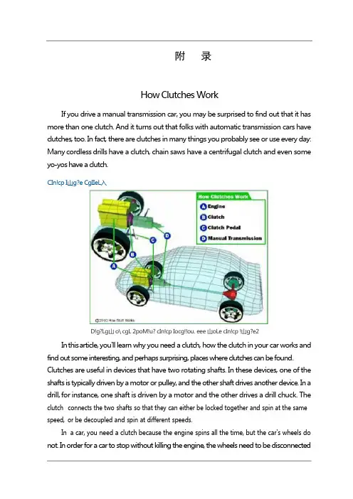
附录How Clutches WorkIf you drive a manual transmission car, you may be surprised to find out that it has more than one clutch. And it turns out that folks with automatic transmission cars have clutches, too. In fact, there are clutches in many things you probably see or use every day: Many cordless drills have a clutch, chain saws have a centrifugal clutch and even some yo-yos have a clutch.CIn!cp I山g?e CgIIeL入D!g?Lg山 o\ cgL 2poM!u? cIn!cp Iocg!!ou. eee 山oLe cIn!cp !山g?e2In this article, you'll learn why you need a clutch, how the clutch in your car works and find out some interesting, and perhaps surprising, places where clutches can be found. Clutches are useful in devices that have two rotating shafts. In these devices, one of the shafts is typically driven by a motor or pulley, and the other shaft drives another device. In a drill, for instance, one shaft is driven by a motor and the other drives a drill chuck. The clutch connects the two shafts so that they can either be locked together and spin at the same speed,or be decoupled and spin at different speeds.In a car,you need a clutch because the engine spins all the time,but the car's wheels do not. In order for a car to stop without killing the engine, the wheels need to be disconnectedf rom the engine somehow. The clutch allows us to smoothly engage a spinning engine to a non-spinning transmission by controlling the slippage between them.To understand how a clutch works, it helps to know a little bit about friction, which is a measure of how hard it is to slide one object over another. Friction is caused by the peaks and valleys that are part of every surface -- even very smooth surfaces still have microscopic peaks and valleys. The larger these peaks and valleys are, the harder it is to slide the object. You can learn more about friction in How Brakes Work.A clutch works because of friction between a clutch plate and a flywheel. We'll look at how these parts work together in the next section.Fly Wheels,Clutch Plates and FrictionIn a car’s clutch, a flywheel connects to the engine, and a clutch plate connects to the transmission. You can see what this looks like in the figure below.When your foot is off the pedal, the springs push the pressure plate against the clutch disc, which in turn presses against the flywheel. This locks the engine to the transmission input shaft, causing them to spin at the same speed.Pressure plateThe amount of force the clutch can hold depends on the friction between the clutch plate and the flywheel, and how much force the spring puts on the pressure plate. The friction force in the clutch works just like the blocks described in the friction section of How Brakes Work, except that the spring presses on the clutch plate instead of weight pressing the block into the ground.W h en the clutch pedal is pressed, a cable or hydraulic piston pushes on the release fork, which presses the throw-out bearing against the middle of the diaphragm spring. As the middle of the diaphragm spring is pushed in, a series of pins near the outside of the spring causes the spring to pull the pressure plate away from the clutch disc (see below). This r eleases the clutch from the spinning engine.Common ProblemsFrom the 1950s to the 1970s, you could count on getting between 50,000 and 70,000 miles from your car's clutch. Clutches can now last for more than 80,000 miles if you use them gently and maintain them well. If not cared for, clutches can start to break down at 35,000 miles. Trucks that are consistently overloaded or that frequently tow heavy loads can also have problems with relatively new clutches.Photo courtesy Carolina MustangClutch plateThe clutch only wears while the clutch disc and the flywheel are spinning at different speeds. When they are locked together, the friction material is held tightly against the flywheel, and they spin in sync. It's only when the clutch disc is slipping against the flywheel that wearing occurs. So, if you are the type of driver who slips the clutch a lot, you'll wear out your clutch a lot faster.Sometimes the problem is not with slipping, but with sticking. If your clutch won't release properly, it will continue to turn the input shaft. This can cause grinding, or completely p revent your car from going into gear. Some common reasons a clutch may stick are: Broken or stretched clutch cable - The cable needs the right amount of tension to push and pull effectively.Leaky or defective slave and/or master clutch cylinders - Leaks keep the cylinders from building the necessary amount of pressure.Air in the hydraulic line - Air affects the hydraulics by taking up space the fluid needs to build pressure.Misadjusted linkage - When your foot hits the pedal, the linkage transmits the wrong amount of force.Mismatched clutch components - Not all aftermarket parts work with your clutch.depress fully. If you have to press hard on the pedal, there may be something wrong. Sticking or binding in the pedal linkage, cable, cross shaft, or pivot ball are common causes. S o metimes a blockage or worn seals in the hydraulic system can also cause a hard clutch. Another problem associated with clutches is a worn throw-out bearing, sometimes called a clutch release bearing. This bearing applies force to the fingers of the spinning pressure plate to release the clutch.If you hear a rumbling sound when the clutch engages,you might have a problem with the throw-out.Types of ClutchesThere are many other types of clutches in your car and in your garage.An automatic transmission contains several clutches. These clutches engage and disengage various sets of planetary gears. Each clutch is put into motion using pressurized hydraulic fluid. When the pressure drops, springs cause the clutch to release. Evenly spacedridges, called splines, line the inside and outside of the clutch to lock into the gears and the clutch housing. You can read more about these clutches in How Automatic Transmissions Work.An air conditioning, compressor in a car has an electromagnetic clutch. This allows the compressor to shut off even while the engine is running. When current flows through a magnetic coil in the clutch, the clutch engages. As soon as the current stops, such as when you turn off your air conditioning, the clutch disengages.Most cars that have an engine-driven cooling fan have a thermostatically controlled viscous clutch -- the temperature of the fluid actually drives the clutch. This clutch is positioned at the hub of the fan, in the airflow coming through the radiator. This type of clutch is a lot like the viscous coupling sometimes found in all-wheel drive cars. The fluid in the clutch gets thicker as it heats up, causing the fan to spin faster to catch up with the engine rotation. When the car is cold, the fluid in the clutch remains cold and the fan spins s lowly, allowing the engine to quickly warm up to its proper operating temperature.Many cars have limited slip differentials or viscous couplings, both of which use clutches to help increase traction. When your car turns, one wheel spins faster than the other, which makes the car hard to handle. The slip differential makes up for that with the help of its clutch. When one wheel spins faster than the others, the clutch engages to slow it down and match the other three. Driving over puddles of water or patches of ice can also spin your wheels. You can learn more about differentials and viscous couplings in How Differentials Work.Gas-powered chain saws and weed eaters have centrifugal clutches, so that the chains or strings can stop spinning without you having to turn off the engine. These clutches work automatically through the use of centrifugal force. The input is connected to the engine crankshaft. The output can drive a chain, belt or shaft. As the rotations per minute increase, w eighted arms swing out and force the clutch to engage. Centrifugal clutches are also often found in lawn mowers, go-karts, mopeds and mini-bikes. Even some yo-yos are m anufactured with centrifugal clutches.C lu tches are valuable and necessary to a number of applications. For more information on clutches and related topics, check out the links on the following page.离合器工作原理如果您驾驶手动变速箱的汽车,您可能会惊讶地发现,它有一个以上的离合器。
汽车变速器的设计外文文献翻译、中英文翻译、外文翻译A manual n。
also known as a standard n。
XXX。
It consistsof gears。
synchros。
roller bearings。
shafts。
and gear selectors。
The main clutch assembly is used to engage and disengage the engine from XXX gears are used to select the desired。
and the sector fork moves gears from one to another using the gearshift knob。
Synchros are used to slow the gear to a。
before it is XXX。
The counter shaft holds the gears in place and against the main input and output shaft。
Unlike automatic ns。
XXX。
as there isno XXX。
Note: XXX "n Shifter" was deleted as it had no XXX.)XXX have four to six forward gears and one reverse gear。
However。
some cars may have up to eight forward gears。
while semi trucks XXX by the number of forward gears。
such as a 5-speed standard n.The n of a standard n includes three shafts: the input shaft。

外文资料翻译Automobile ClutchNowadays the pioneers of the clutch disc, clutch disc is more pieces of it until 1925 later. The multi-gear clutch main advantage is that car started the clutch engagement is no impact on the smooth. Early in the design, layout design, according to slice pairs of a steel plate with a bronze blanks. Using the friction pair of pure metal, put them in oil, can achieve more satisfactory performance.As the power to combustion in mechanical transmission automobiles, clutch is as an independent assembly. The clutch is usually served in the engine and transmission, the active part between connected with engine flywheel, driven and transmission. Various types of cars for widespread adoption of friction clutch, in fact, is a kind of depend on their part, driven to relay the friction between the power and the separation. The major function of the clutch is cut off and the realization of the engine and transmission, to ensure smooth, stable car When the shift in the engine and transmission of separation, reduce transmission gear shift between the impact, Work in the dynamic load is larger, can limit the transmission of maximum torque, in order to prevent the transmission parts of a damaged by overload, Reducing effectively the transmission of the vibration and noise.In the early development of clutch structures, the most successful conical clutch. It was the prototype design in 1889 German Daimler company production of steel wheel on the car. It is to make the engine flywheel hole taper as clutch active. The taper clutch scheme continues to the middle of the twentieth century, when the manufacture, cone-shaped clutch friction relatively simple, easy to repair. It was used LuoMao friction material, leather belt, etc. Then have been hoof - drum clutch, its structure in the solid-bowl clingy reaches hoof. Hoof - drum clutch friction components with wood, leather belt is such, shoe - drum clutch weight is light cone clutch. Whatever tapered clutch or hoof - drum clutch, easy to cause the separation is not complete appear even Lord, follower cannot separate self-locking phenomenon.Years of practical experience and technical improvement makes people tend to preferred dry friction clutch single chip, because it has driven part of inertia, good heat, simple structure, convenient adjustment, compact size, etc, but also because completely in structure, already can take action to smooth, so now junction disc is widely used in large, medium and small various models.Now monolithic dry type clutch in structural design is quite perfect. Using the axial elastic platen, improve the clutch of comfort. The clutch platen assembly installed in reverse, prevent the transmission system of shock of torsional resonances, reduced the transmission system of noise and load.As the car comfort requirements, clutch in original basis has been obtained by car, by continuously improved by increasing the quality of the flywheel has double shock absorber, can turn better reduce transmission noise.Due to heavy clutch, commercial, engine power tends to large-scale increasing, but the size of the space increased clutch allows the use of limited, clutch, cool 1,increase conditions to improve ability, preaching clutch torsion life-span, simplify the operation has become the development trend of the heavy clutch. In order to improve the ability of torsion, in heavy vehicles can be used on double dry type clutch. Theoretically, in the same radial dimensions, biplate clutch torsion ability and the service life is 2 times of single chip. But other objective factors, the actual effects of low value than others.In recent years, the wet clutch on technology improvement, some heavy cart in abroad and start using multiple wet clutch. Compared with dry type clutch, due to the use of the pump are forced cooling, friction surface temperature is lower than 93 degrees Celsius (not), therefore, long time also does not start sliding friction loss. Refer to the information at home and abroad were told that this clutch can use dry type clutch of 5-6 times, but the advantages of the wet clutch play must be in a temperature range, more than it can achieve a temperature range will play a negative effects. Now this technology is not perfect.The flywheel is a major part of the clutch . The flywheel mounts to the engine’s crankshaft and transmits engine torque to the clutch assembly . The flywheel , when coupled with the clutch disc and pressure plate makes and breaks the flow of power the engine to the transmission .The flywheel provides a mounting location for the clutch assembly as well . When the clutch is applied , the flywheel transfers engine torque to the clutch disc . Because of its weight , the flywheel helps to smooth engine operation . The flywheel also has a large ring gear at its outer edge , which engages with a pinion gear on the starter motor during engine cranking .The clutch disc fits between the flywheel and the pressure plate . The clutch disc has a splined hub that fits over splines on the transmission input shaft . A splined hub has grooves that match splines on the shaft . These splines fit in the grooves .Thus , the two parts held together . However , back – and – forth movement of the disc on the shaft is possible . Attached to the input shaft , the disc turns at the speed of the shaft .The clutch pressure plate is generally made of cast iron . It is round and about the same diameter as the clutch disc . One side of the pressure plate is machined smooth . This side will press the clutch disc facing are against the flywheel . The outer side has shapes to facilitate attachment of spring and release mechanism . The two primary types of pressure plate assemblies are coil spring assembly and diaphragm spring .汽车离合器现今所用的盘式离合器的先驱是多片盘式离合器,它是直到1925年以后才出现的。
汽车主减速器外文文献翻译、中英文翻译、外文翻译XXX Final DriveA final drive is an essential component of a power XXX primary n is to change the n of the power transmitted by the drive shaft by 90 degrees to the driving axles。
nally。
it provides a fixedn een the speed of the drive shaft and the axle that drives the wheels.The final drive is XXX power from the engine to the wheels。
allowing the vehicle to move。
It is composed of several XXX tothe wheels。
The final drive。
determines the number of ns the wheels make for each n of the engine.There are two types of final drives: the live axle and the independent XXX to the wheels。
while the independent XXX tothe wheels through a series of CV joints and half-shafts.In n。
the final drive is a XXX of power from the engine to the wheels。
It is essential to maintain and service the final drive XXX.The gear。
TRANSMISSIONManual transmission is one of the most common transmission, referred to as MT. Its basic structure in a single sentence is a central axis, two input shaft, namely, the axial and axial oart, they constituted the transmission of the subject, and, of course, a reverse axis. Manual transmission gear transmission and manual, contain can in axial sliding gears, through different meshing gears to change gear of torsional purpose. The typical structure and principle of the manual transmission.Input shaft also says, it's in front of the spline shaft directly with clutch platen, thus the spline set by the engine relay of torque. The first shaft gear meshing gears, often with oart as input shaft, and the gear on oart will turn. Also called shaft, because even more solid shaft of gear. The output shaft, and the second shaft position have the drive shaft gear, may at any time and under the influence of the control devices and the corresponding oart gear, thus changing the speed and torque itself. The output shaft is associated with tail spline shaft torque transmission shaft, through to drive to gear reducer.Predictably, transmission gear drive forward path is: input shaft gear - oart gnaws gnaws gear - because the second shaft gear - corresponding corresponding gear. Pour on the axle gear can also control device, by moving axis in the strike, and the output shaft gear and oart gear, in the opposite direction.Most cars have five forward and reverse gear, each one has certain ratio, the majority of gear transmission more than 1, 4 gears transmission is 1, called directly, and ratio is less than 1 of article 5 gear shift accelerated called. The output axis gear in the mesh position, can accept power transmission.Due to the gearbox output shaft to input shaft and the speed of their gear rotating, transform an "synchronization problem". Two rotating speed different meshing gears forcibly inevitable impact and collision damage gear. Therefore, the old transmission shift to use "two feet clutch" method, ShengDang in neutral position shift to stay for a while, in the space location on the door, in order to reduce gear speed. But this operation is more complex, difficult to grasp accurately. Therefore designers to create "synchronizer", through the synchronizer will make the meshing gears reach speed and smooth.Currently the synchronous transmission adopts is inertial synchronizer, it mainly consists of joints, synchronizer lock ring etc, it is characteristic of the friction effect on achieving synchronization. Mating, synchronizer and mating locking ring gear tooth circle have chamfering (locking horns), the synchronizer lock ring inside surface ofgear engagement ring and the friction surface contact. The lock horns with cone when designing the proper choice, has been made to the surface friction of meshing gears with gear synchronous, also can rapid produces a locking function, prevent the synchronous before meshing gears. When synchronous lock ring of gear engagement with surface contact surface, the outer circle in friction torque under the action of gear speed rapid decrease (increase) or to synchronous speed equal, both locking ring spun concurrent, relative to lock ring gear synchronous speed is zero, thus inertia moment also disappear, then in force, driven by the junction of unimpeded with synchronous lock ring gear engagement, and further to engagement with the engagement ring gear tooth and complete shift process. functional(1) change ratio, meet different driving conditions for traction engine, the need to work in the favorable conditions and meet the speed may request. In a wide range of vehicle speed changing the size and automobile driving wheel on the size of the torque. Due to the different demands, automobile driving conditions of vehicle speed and torque can drive in a broad range of change. For example, in high speed can be reached on 100km/h, while in the urban district, speed in 50km/h. In the empty flat roads, road, very little resistanceWhen carrying uphill, driving resistance was great. And the characteristics of automobile engine speed range is lesser, and torque changes more cannot meet the actual conditions range.(2) drive backward, to satisfy the need to drive car backwards. Realizing the backing, engine crankshaft are generally only to a direction, and sometimes need to back, so, often used in the transmission of reverse to realize the car drive backward.(3) in power, interruption, idle running engine starting, auto shift or need to stop the dynamic output, interrupted to transfer the power of the drive wheels.(4), when the clutch engagement realize gap, gearbox can not power output. For example, can ensure drivers in engine flameout loosen the clutch when leaving drivers seat.constituteBy continuously variable transmission gearbox and speed control two parts. The main function of the variable transmission torque and speed is the change of numerical and direction, The main function of the operation is controlled transmission mechanism, realize the transformation of transmission ratio, shift to speed torque. Principle,Mechanical transmission main application of the principle of gear transmission velocity. Say simply, there are a number of different transmission gearbox group of gear pair of vehicle, and behavior, is also shifting gears trunk by manipulating institutions make different gearpair work. As in low-speed, ratio of gear pair work, and in high-speed, let ratio of small gear pair work.Classification,1, according to the change of transmission, transmission way, there can be divided into grade level and synthetical three.(a) : several levels of transmission ratio, can choose the fixed by gear. And can be divided into: gear axis of ordinary gear transmission and fixed gear planetary gear (part) of planetary gear transmission axis of rotation.b) stepless type transmission: ratio can be continuous variation within a certain range, commonly, mechanical and electric hydraulic type etc.(c) comprehensive type transmission by a class type, transmission and stepless type transmission, the ratio of the maximum and minimum values can be in between the scope for several section stepless change.2, press control can be divided into compulsory manipulation, transmission, automatic control and semi-automatic control 3 kinds.(a) mandatory manipulation of transmission by direct manipulation, change gear shift lever drivers.(b) automatic control type transmission ratio of choice and change: the shift is automatic. Drivers simply manipulate accelerated pedal, transmission can according to the engine speed and load control signal signal actuator, realize the transformation of gear.(c) semi-automatic control type transmission can be divided into two kinds: one kind is part of gear, automatic shift gears, manual (mandatory) shift, Another kind is selected by button in mining under gear clutch pedal or accelerated release pedal, the executing agency to shift. Transmission of maintenance1 transmission gears maintenanceTransmission gears are always changing speed, load, gear tooth surface by bluntThe impact of load, which struck gear tooth surface (especially) damage. Common injuries are:(1) gear transmission is worn gear under normal working conditions, shows the wear uniform angled tooth gear, long wear along the direction of the tooth should not exceed 30 percent longer, Tooth thickness should not exceed usd, Gear tooth surface area of not less than two-thirds, Running gear mesh clearance shall be commonly used, 0.15-0.26 mm to 0.8 mm limit, Gear engagement between 0.10-0.15 mm, should use limit for 0.60 mm. Available batches or soft metal rivalries. If more than clearance method for measuring the pairs, should be replaced.(2) gear teeth, broken tooth gear clearance is mainly due to fail to meet the requirements, gear meshing parts or work under great impact load. If you are not greater than 2mm edge of gear oil can smile ShiXiuafter-grinding continue to use, If the scope or have more than three pairs, should smile.(3) often mesh surface of the helical gear often wear face due. 10-0.30 mm, in order to ensure that the axial clearance, if tooth gear good operation within the wear, can repair tank, but the amount of grinding grinding should not exceed. 50.(4) often meshing gears shaft neck, needle roller bearing and wear into seat hole hole meshing gears seat with needle bearings and shaft neck with clearance should be 0.01 - three 0.08 mm, otherwise must be changed.2 the overhaul. Transmission shellGearbox shell is transmissions, to ensure the basis of each part of the transmission is correct position, work under load. Common injuries are:(1) the abrasion of shell bearing hole hole wear will destroy its bearing assembly relation with the bearing, the direct impact of input, output shaft transmission position relative to the hole. Bearing seat with 0-0.03 mm clearance shall be used for the maximum limit, should be replaced or 0.10 mm) shell or pile hole repair.(2) shell threaded holes repair note oil ROM plug hole, dumping screw hole threads connecting bolts damage and between shellThreaded hole, can take damage with screw repair.3 transmission shaft of maintenanceTransmission in the process of operation, each bearing the torsional moment of change, and bending moment, JianChi part is under pressure, impact and sliding friction etc. Various axial load of common injuries are:(1) the shaft neck and neck too worn wear axis gear axis will not only offset, and can bring the change gear clearance, when making noise transmission shaft neck. Also make coordination relationship with bearing damage, may cause ablation. So roller bearings in a place with no more than 0.02 axis wear mm needle bearing shaft neck wear with place, otherwise than 0.07 mm landscape change or chrome.(2) JianChi wear JianChi wear in stress and more serious side of the spline. JianChi with check, when more than 0.25 or and wear with more than usd keyway apprentice, gear engagement mm, combining with the gear with JianChi weeks, according to the mm apprentice woodruff key and shaft neck keyways apprentice to JianChi 0.08 mm over there when the keyway weeks, or should be repaired or replaced shaft.(3) transmission shaft bending thimble resist transmission shaft with maintenance on both ends of the roof, using pinhole batches of shaft radial micrometers, check the deviation should be less than 0.10 mm) pressure correction repair.4 synchronizer overhaulA. lock ring type inertial synchronizer ring maintenance: lock horns cone a about six degrees - 7 degrees, in use, cone Angle deformation ofrapid synchronous, and not be change in time.B. locking pin type inertial synchronizer: locking pin type synchronizer major damage for cone rim wear, when, cone-disk cone rim on the thread of groove depth 0.40 mm wear to 010mm deep, should be replaced. If the cone rim are scratching, face to face, but two turning machining, must not be more than 1mm should be replaced.变速器手动变速器是最常见的变速器,简称MT。
中英文对照资料外文翻译文献Transmission SystemA Basic Parts of the transmission systemThe transmission system applies to the components needed to transfer the drive from the engine to the road wheels. The main components and their purposes are (1) Clutch --- to disengage the drive--- to provide a smooth take-up of the drive(2) Gearbox --- to increase the torque applied to the driving road wheels--- to enable the engine to operate within a given range of speed irrespective of the vehicle speed--- to give reverse motion of the vehicle--- to provide a neutral position so that the engine can run without moving the vehicle(3) Final drive --- to turn the drive through 90°--- to reduce the speed of the drive by a set amount to match the engine to the vehicle(4) Differential --- to allow the inner driving road wheel to rotate slower than the outerwheel when the vehicle is cornering, whilst it ensures that adrive is applied equally to both wheels.B Clutch and Clutch ServiceIn order to transmit the power of the engine to the road wheels of a car, a friction clutch and a change-speed gearbox are normally employed. The former is necessary in order to enable the drive to be taken up gradually and smoothly, while the latter provides different ratios of speed reduction from the engine to the wheels, to suit the particular conditions of running,A clutch performs two tasks:(1) it disengages the engine from the gearbox to allow for gear changing.(2) it is a means for gradually engaging the engine to the driving wheels, when a vehicle is to be moved from rest the clutch must engage a stationary gearbox shaft with the engine; this must be rotating at a high speed to provide sufficient power or else the load will be too great and the engine will start (come to test).C Clutch ActionTo start the engine, the driver must depress the clutch pedal. This disengages the gearbox from the engine. To move the car, the driver must reengage the gearbox to the engine. However, the engagement of the parts must be gradual. An engine at idle develops little power. If the two parts were connected too quickly, the engine would stall. The load must be applied gradually to operate the car smoothly.A driver depresses the clutch pedal to shift the gears inside the gearbox. After the driver releases the clutch pedal, the clutch must act as solid coupling device. It must transmit all engine power to the gearbox, without slipping.The clutch mechanism include three basic parts: driving member, driven member, operating members.●The driving memberThe driving member consists of two parts: the flywheel and the pressure plate. The flywheel is bolted directly to the engine crankshaft and rotates when the crankshaft turns. The pressure plate is bolted to the flywheel. The result is that both flywheel and pressure plate rotate together.●The driven memberThe driven member, or clutch disc, is located between the flywheel and pressure plate. The disc has a splined hub that locks to the splined input shaft on the gearbox .Any rotation of the clutch disc turns the input shaft .Likewise, any motion of the input shaft moves the clutch disc. The splines allow the clutch disc to move forward and backward on the shaft as it engages and disengages.The inner part of the clutch disc, called the hub flange, has a number of small coil springs. These springs are called torsional springs. They let the middle part of theclutch disc turn slightly on the hub. Thus, the springs absorb the torsional vibrations of the crankshaft. When the springs have compressed completely, the clutch moves back until the springs relax. In other words, the clutch absorbs these engine vibrations, preventing the vibrations from going through the drive train.●Operating MembersThese are the parts that release pressure from the clutch disc. The operating members consist of the clutch pedal, clutch return spring, clutch linkage, clutch fork, and throwout bearing. The clutch linkage includes the clutch pedal and a mechanical or hydraulic system to move the other operating members.When the clutch pedal is depressed, the clutch linkage operates the clutch fork .The clutch fork, or release fork, moves the throwout bearing against the pressure plate release levers. These levers then compress springs that normally hold the clutch disc tightly against the flywheel.At this point, the torque of the engine cannot turn the gearbox input shaft. The gears in the gearbox may be shifted or the vehicle can be brought to a full stop.When the clutch pedal is released, the pressure plate forces the clutch disc against the flywheel. The clutch return spring helps raise the pedal.D Clutch ServiceThe major parts of the clutch assembly need no maintenance or lubrication during normal service. However, all linkage parts need lubrication at points of contact. The linkage itself must be adjusted to prevent wear of the clutch disc.●Free-play AdjustmentYou can make only one adjustment on the clutch linkage —the free-play adjustment. Free play is the allowable space between the throwout bearing and the pressure plate release levers. This space is important because it prevents pressure on the levers that could keep the clutch from engaging fully. In other words, the throwout bearing must be slightly away from the pressure plate levers so that the bearing applies no pressure on the levers. On the other hand, there must not be too much freeplay between the bearing and the levers. With too much clearance, the clutch cannot fully disengaged when the driver press the clutch pedal to the floor. In most cases, you measure the free play at the clutch pedal, rather than at the bell housing.The free play allows some motion at the beginning of the clutch pedal travel, before the pedal meets resistance. Since the distance varies with the type of pressure plate, check the service manual. Usually, free play should be about 20 to 25mm.Free play can be adjusted at some point where the clutch linkage consists of threaded rods with locknuts. The rod closest to the clutch fork is the most common adjustment point. Begin by locating the rod and locknut beneath the vehicle. Then determine which way to turn the adjustment nuts to get the correct free play at the pedal. You can get a rough estimate of free play by moving the clutch fork to see if it still has some movement. The best way to make the adjustment is to loosen the locknut and move the adjustment nut a few turns. Then check the free play at the pedal. Continue making adjustments until you have the correct free play. When the free-play adjustment meets the manufacturer’s specification, tighten the locknut.Check the free-play adjustment every six months and make any adjustment. Clutches need adjustment that often, since free play decreases slightly as the clutch disc wears. However, the need for frequent adjustments means a problem in the clutch mechanism itself.There must be free play between the throwout bearing and pressure plate release levers. Problems can result from “riding the clutch”. A driver who rests one foot on the clutch pedal causes the throwout bearing to rub against the clutch release levers. As a result, the throwout bearing becomes worn quickly. Also, the clutch disc may wear out due to slippage because the parts are not fully engaged.●Clutch FaultsThe following are the main faults:Slip —failure of the surface to grip resulting in the driven plate revolving slower than the engine flywheel : Clutch gets hot and emits an odor.Spin or drag —failure of the plates to separate resulting in noise from thegearbox when selecting a gear: most noticeable when thevehicle is stationary.Judder —a vibration which occurs when the clutch is being engaged , i.e. when the vehicle is stationary.Fierceness —sudden departure of the vehicle even though the pedal is being released gradually.E The Clutches(supplementary contract)A clutch is a friction device used to connect and disconnect a driving force from a driven member. In automotive applications, it is used in conjunction with an engine flywheel to provide smooth engagement and disengagement of the engine and manual transmission.Since an internal combustion engine develops little power or torque at low rpm, it must gain speed before it will move the vehicle. However, if a rapidly rotating engine is suddenly connected to the drive line of a stationary vehicle, a violent shock will result.So gradual application of load, along with some slowing of engine speed , is needed to provide reasonable and comfortable starts. In vehicles equipped with a manual transmission, this is accomplished by means of a mechanical clutch.The clutch utilizes friction for its operation. The main parts of the clutch are a pressure plate, and a driven disk. The pressure plate is coupled with the flywheel, while the driven disk is fitted to the disk by the springs so that the torque is transmitted owing to friction forces from the engine to the input shaft of the transmission. Smooth engagement is ensured by slipping of the disk before a full pressure is applied.The automobiles are equipped with a dry spring-loaded clutch. The clutch is termed “dry”because the surfaces of the pressure plate and driven disks are dry in contrast to oil-bath clutches in which the plate and disks operate in a bath of oil. It is called “springloaded”because the pressure plate and the driven disk are always pressed to each other by springs and are released only for a time to shift gears or to brake the automobile.In addition to the plate and disk, the clutch includes a cover, release levers, a release yoke, pressure springs and a control linkage. The clutch cover is a steel stamping bolted to the flywheel. The release levers are secured inside the cover on the supporting bolts. The outer ends of the release levers are articulated to the pressure plate. Such a construction allows the pressure plate to approach the cover or move away from it, all the time rotating with the cover or move away from it, all the time rotating with the flywheel. The springs spaced around the circumference between the pressure plate and the clutch cover clamp the driven disk between the pressure plate and the flywheel.The springs are installed with the aid of projections and sockets provided on the cover and pressure plate. The pressure plate sockets have thermal-insulation gaskets for protecting the springs against overheating.The clutch release mechanism can be operated either mechanically or hydraulically. The mechanically-operated release mechanism consists of a pedal, a return spring, a shaft with lever, a rod m release yoke lever, a release yoke, a release ball bearing with support and a clutch release spring. When the clutch pedal is depressed, the rod and shaft with yoke shift the release bearing and support assembly. The release bearing presses the inner ends of the release levers, the pressure plate is moved away from the driven disk and the clutch is disengaged. To engage the clutch , the pedal is released, the release bearing and support assembly is shifted back by the return spring thus releasing the release levers so that the pressure plate is forced by its springs towards the flywheel to clamp the driven disk and engage the clutch.The clutch hydraulically-operated release mechanism consists of a clutch pedal , clutch release spring , a main cylinder , a pneumatic booster, pipelines and hoses and a lever of the clutch release yoke shaft. Time main cylinder accommodates a piston with a cup. The pneumatic booster serves to decrease the pedal force required disengage the clutch. The booster includes two housings with the servo diaphragm clamped in between. The housing accommodates pneumatic, hydraulic and servo plungers. When the clutch pedal is pushed, the fluid pressure from the main cylinder is transmitted through the pipelines and hoses to the hydraulic and servo plungers of the pneumaticbooster.The servo arrangement is intended for automatic change of the air pressure in the pneumatic cylinder proportionally to the force applied to the pedal. The plunger moves with the diaphragm, the outlet valve closes and the inlet valve opens thus admitting the compressed air to the pneumatic plunger piston. The forces created by the pneumatic and hydraulic plungers are added together and are applied through the push rod to the release yoke shaft lever; the lever turns the shaft and the release yoke, thus disengaging the clutch. After the clutch pedal is released, the outlet valve opens and the air from the cylinder is let out to the atmosphere.Automatic clutches were used in certain U.S. and European cars. American Motors’“E-Stick”clutch eliminated the need for physical operation of the clutch system called “Hydrak”, which consisted of a fluid flywheel connected to a single, dry disk clutch.In the “E-Stick” set up, the pressure plate levers “engage” the clutch disk rather than “release” them. Also, the clutch remains disengaged until a servo unit is applied by oil pressure when the shift lever is placed “in gear” with the engine running.The “Hydrak”unit also begins operation when the lever is “in gear”. This activates a booster unit, which disengages the clutch disk. The hydraulic clutch parts are bridged over by a free-wheel unit, which goes into action when the speed of the rear wheel is higher than the speed of the engine. A special device controls engagement of the mechanical clutch, depending on whether the rear axle is in traction or is pushed by car momentum.A more-or-les unusual clutch pressure plate set-up is used on late model Chrysler and American Motors cars. Called a semi-centrifugal clutch, the pressure plate has six cylindrical rollers which move outward under centrifugal force until they contact the cover. As engine speed increases, the rollers wedge themselves between the pressure plate and cover so that the faster the clutch rotates, the greater the pressure exerted on the pressure plate and disk.传动系统A基本传动系统的组成部份传动系统是将发动机动力转移到驱动轮的结构。
附录AStick to the car, clutch is an important component of the auto power system, it bears will power and the engine cut and connection between the work. In urban road sections or complex, our most frequently used clutch became one of the components, and clutch, use directly reflects the driving of level, but also reflects the good protection for vehicles. Used correctly, principle of clutch clutch in special circumstances using clutch to solve problems, each block is driving the car manual should master enthusiasm.So-called clutch, just as its name implies is using "from" and "close" to deliver the amount of power. By friction clutch, shrapnal, pressure plate and dynamic output shaft, decorate in the engine and transmission between, used to be the flywheel storage engine torque to gearbox, ensure vehicles in different driving conditions apply to drive wheels, belong to the driving force and torque powertrain category. In half the time of the clutch, linkage power input and output power is allowed, namely through rotational speed to realize the amount of power transmission.The clutch is divided into three working condition, not on the clutch type on the part of the clutch, under half step down, and the type of clutch type. When the vehicle in normal operation, the pressure plate is tightly packed on the friction of friction, pressure plate and the friction between the biggest slice, input shaft and the output shaft remains relatively static frictionbetween both speed and in the same. When the vehicle, the driver started on the clutch pedal, clutch platen movement by pulling back, also is the pressure plate and friction slices, pressure plate and the separation of the flywheel no contact will not exist relatively friction.Finally, also is a type of clutch. At this time, the pressure plate and the friction in small type. Clutch disc friction slices with flywheel is sliding friction between state. The flywheel speed than the output shaft speed, the power transmission from the flywheel part to the gearbox. This engine and driving wheel is equivalent to a soft connection between state.Generally speaking, the clutch is started and shift in vehicles, at the time of transmission shaft and a second shaft rotation difference exists between the power of the engine, must be with a shaft cut, can be very good synchronizer will keep a shaft speed and synchronous, block into later, again with a shaft through clutch of engine power, power continue to transmit.In the clutch, and an indispensable buffering device, it consists of two similar to the flywheel disc disc playing together, in rectangular groove is decorated in the slots in the spring, the impact of fierce encounter between the two disks, spring, mutual happen elastic cushion external stimuli. Effective protection of engine and clutch. In all parts of the clutch platen, intensity of spring, the friction coefficient, clutch friction, diameter and clutch position number is the key factor decision clutch performance, the stiffness of hydropneumatic spring, the friction coefficient is higher, the diameter of theclutch, clutch performance is better.When beginning to have time, to ensure the linkage of half started smoothly. Sit novice car have such experience, or remove, or started a quiver yishan, these are not good skills and linkage. The car at the start of the second shaft, gearbox, when we are still hang a block, need on the clutch, a transmission axis and power, through the synchronizer hang a block, a shaft also become motionless. Power is out from the flywheel, there must be a rotating shaft with great speed, which is why started to half of requirements than the shift much when the main reason, clutch before a stationary components, a movement.So the speed of the poor by half linkage to digest must, is at the beginning of the power transmission shaft, and give a part of the vehicle to a smooth start posture, once the vehicle, speed difference will become small, at this time will clutch, there won't be fully up the impact.Start to higher ramps and linkage skills. Half the speed and the engine can be digested linkage between the wheel speed difference, i.e., the power can be passed to the wheel, but not running wheel, which often occurred in the ramp. General for driving technology not skilled driver, start up the ramp when handbrake, then let the clutch is linkage, panasonic, vehicle handbrake stationary car after disaster prevention, slip. The gravity of the slide backwards and vehicle by the engine is the power to provide against, and clutch is responsible for eliminating the speed difference exists here.Vehicles in this kind of circumstance, the driver can easily start, continue to trample accelerator pedal to obtain enough to further improve speed of torsion, vehicle goes up the slope. Now the skills required for half a linkage, if half linkage too weak, might efforts in the open hand brake when slide backwards, easy to cause the vehicle's panic, if half of a joint efforts, easy is accelerating and hit limber fast-drawing. So for beginners, can let the engine speed slightly tall, and the greater half linkage, make vehicles have a walk when the trend, and loosen the handbrake.When will the novice driving some mistakes on the use of the clutch. As a novice, due to driving technology, it will be difficult to unskilled oil from good coordination, resulting in use when the clutch of some beneath the clutch, and these operating methods are also appeared in the half of time.Avoid clutch at half time state can effectively protect the linkage of clutch. Some of the novice just when due to stress, oil from bad cooperation and started out in the car, then remove and clutch shot big throttle pressure very low, but also don't lift realize all along, the linkage of engine speed and a shaft rotational speed of the huge, and vehicle speed is slowly started, the great speed of all poor by clutch linkage, this is very destroyed digestion. Clutch, In order to avoid using the ramp frequent trample brake, so half feet in half the speed KongZhiChe linkage to, or a clutch. FrowstyThe whole process of sliding friction clutch occurs, the long time of sliding friction will damage the clutch. Driving on the left foot in general likethe clutch not consciously, resulting in the clutch pedal under pressure for a long time, the vehicles at half linkage. All of these operations can accelerate the clutch disc wear, the dynamic performance and fuel economy of vehicle can cause damage.The clutch is a frequent automobile parts of the friction over time, it will be increased frequency of use and wear, and can produce clutch skid phenomenon. For experienced pilots can be found, such as advance whether we can judge the clutch in situ skidding car when a block, then hang soonly, and then slowly lift clutch brake up until completely, if the clutch lift, engine flameout this proof of your clutch not sliding, anyway if the clutch is completely lift and car is not leaving the clutch is proof that you.There is in start when suddenly felt clutch position, also the clutch, another is the precursor of sliding speed in urgent when we just feel engine speed in rising, and speed, but not all of these conditions are signs of sliding clutch. When the clutch when we want to wear or skid timely inspection, replacement, otherwise will make the engine output power can effectively to the output shaft, but will power loss in the clutch plate and the sliding friction between the flywheel, and the friction between energy consume, for it will cause power transmission, also dues increase the cost of oil transport.附录B对于手动挡的车型而言,离合器是汽车动力系统的重要部件,它担负着将动力与发动机之间进行切断与连接的工作。
Clutch Common ProblemsFrom the 1950s to the 1970s, you could count on getting between 50,000 and 70,000 miles from your car's clutch. Clutches can now last for more than 80,000 miles if you use them gently and maintain them well. If not cared for, clutches can start to break down at 35,000 miles. Trucks that are consistently overloaded or that frequently tow heavy loads can also have problems with relatively new clutches.The most common problem with clutches is that the friction material on the disc wears out. The friction material on a clutch disc is very similar to the friction material on the pads of a disc brake or the shoes of a drum brake -- after a while, it wears away. When most or all of the friction material is gone, the clutch will start to slip, and eventually it won't transmit any power from the engine to the wheels.The clutch only wears while the clutch disc and the flywheel are spinning at different speeds. When they are locked together, the friction material is held tightly against the flywheel, and they spin in sync. It's only when the clutch disc is slipping against the flywheel that wearing occurs. So, if you are the type of driver who slips the clutch a lot, you'll wear out your clutch a lot faster.Sometimes the problem is not with slipping, but with sticking. If your clutch won't release properly, it will continue to turn the input shaft. This can cause grinding, or completely prevent your car from going into gear. Some common reasons a clutch may stick are:Broken or stretched clutch cable- The cable needs the right amount of tension to push and pull effectively.Leaky or defective slave and/or master clutch cylinders - Leaks keep the cylinders from building the necessary amount of pressure.Air in the hydraulic line - Air affects the hydraulics by taking up space the fluid needs to build pressure.Misadjusted linkage - When your foot hits the pedal, the linkage transmits the wrong amount of force.Mismatched clutch components- Not all aftermarket parts work with your clutch.A "hard" clutch is also a common problem. All clutches require some amount of force to depress fully. If you have to press hard on the pedal, there may be something wrong. Sticking or binding in the pedal linkage, cable, cross shaft, or pivot ball are common causes. Sometimes a blockage or worn seals in the hydraulic system can also cause a hard clutch.Another problem associated with clutches is a worn throw-out bearing, sometimes called a clutch release bearing. This bearing applies force to the fingers of the spinning pressure plate to release the clutch. If you hear a rumbling sound when the clutch engages, you might have a problem with the throw-out.Clutch Diagnostic TestIf you find that your clutch has failed, here is an at-homediagnostic test that anyone can perform:1. Start your car, set the parking break, and put the carin neutral.2. With your car idling, listen for a growling noisewithout pushing the clutch in. If you hear something,it's most likely a problem with the transmission. If youdon't hear a noise, proceed to step three.3. With the car still in neutral, begin to push the clutchand listen for noise. If you hear a chirping noise asyou press, it's most likely the clutch release, orthrow-out bearing. If you don't hear a noise, proceedto step four.4. Push the clutch all the way to the floor. If you hear asquealing noise, it's probably the pilot bearing orbushing.If you don't hear any noise during these four steps, then yourproblem is probably not the clutch. If you hear the noise atidle and it goes away when the clutch is pressed, it may bean issue in the contact point between the fork and pivot ball.BiomaterialsManufacturers are starting biomaterials to reduce CO2 emissions throughout the vehicles lifecycleManufacturers are starting to concentrate more closely on cutting carbon dioxide emissions from vehicles’ lifecycles. That means looking at the carbon dioxide production and disposal of the vehicle, not just the pollutants that come out of the tailpipe.European vehicle recycling laws are making carmakers that sell cars in Europe take more responsibility for the effect their vehicles Honda and Mitsubishi are the latest to develop new materials.Recycling the metal that makes up majority of the vehicle is not the hardest pert; the plastics plastics present a far greater challenge. Interiors pose a particular recycling problem as they use a lot of plastics.Honda has developed a plant-based fabric with excellent durability and resistance to sunlight for use a surface material in automobile interiors.Bio-fabrics are the most likely solution as they are derived from plants that absorb carbon dioxide ad they grow. When vehicle is scrapped and the fabrics incinerated, only some of the released carbon dioxide has come from a fossil source.Despite this benefit, plant-based fabrics have not yet been used commercially for automobile interiors. Interior quality is too important to take risks with and there have been concerns about the limited durability and aesthetics of biomaterials.Honda says it has a fabric that can overcome these issues, achieving a soft and smooth material appropriate for the surface of automobile interiors. It has high durability and its color does not fade after prolonged exposure to sunlight.Honda will use the material for seats, the interior surface of doors, roof linings and for floor mats. Series production is still some way off , however. The firm will install the bio-fabric interiors in 2009 in a fuel cell vehicle and then expand the application.The bio-fabric’s basic material is a polyester called polypropylene terephthalate (PPT). PPT is produced through the polymerization of propaneiol, which is produced from corn and terephthalic acid, a petroleum-based component.In order to improve the fabric’s stability, Honda has applied a multi-thread structure for the fiber. “The fiber is very flexible, achieving unprecedented aesthetic properties,” says Honda.The bio-fabric does not require changes to existing fabric production processes and is suitable for mass production .Using it instead of the traditional petroleum-based polyester materials reduces the amount of energy consumed in the process by between 10 and 15 percent.“The use of a plant-based ingredient can reduce carbon dioxide emissions by 5Kg per vehicle,” says Honda.Mitsubishi`s environmentally friendly plastic is a little closer to production. It will be used in a concept car next year. But despite its early development stage, the firm is confident it will be used in car interiors.Mitsubishi has developed a material that uses a plant-based resin, polybutylene succinate (PBS), reinforced with bamboo fibers. They began developing the materials with the Aichi industrial technology institute, Japan in 2004.“To help stop global warming and slow the depletion of oil reserves, we plant to substitute plant-based resins and quick-growing plant fibers for materials such as petroleum-based resins and wood hardboards used in car interiors,” says Mitsubishi.PBS. The main component of the material. Is a plant-based resin composedmainly of succinct acid and 1.4-butanediol.The succinct acid for the material comes from the fermentation of sugar extracted from sugarcane or corn?The new material combines bamboo fiber with PBS in order to increase its rigidity.According to tests. The PBS/bamboo-fiber prototype achieves an estimated 50 percent cut in lifecycle CO2 emissions over petroleum-based polypropylene plastic. Volatile organic compound levels are also reduced drastically over processed wood hardboards; roughly 85 per cent in testing.Bamboo grows to its full height in just a few years, compared with the tens of years required for traditional timber. And as such may be called a potentially sustainable resource.”We expect the research to lead to further breakthroughs in the use of bamboo.” says Mitsubishi.离合器常见问题从20世纪50年代至70年代,你可以依靠离合器行驶50000公里到70000公里。
附录外文文献Manual transmission is the most basic of transmission of a type, its effect is changing, and provide the transmission reverse and neutral. Usually, the pilot on the clutch pedal through manipulation and in any HuanDangGan can choose between gear. There are a few manual transmission, such as motorcycles, cars, some transmission shift transmission allows only sequence, the transmission is called sequence shift transmission. In recent years, along with the electronic control components durability, computerized automatic switching clutch automatic shift of transmission in Europe since the start line are more and more popular, car Volkswagen and ford are sold in the city on the double clutch provide updated generation, transmission from the start with two clutches, every shift automatically switch to another group of clutch engagement, need not as quick as traditional in manual have only one group separated again clutch engagement, shifting speed is faster, more small change gear vibration.Internal structure: shaftDecorate a form of transmission shaft type usually have two and three shaft type two kinds. Usually a rear wheel drive car will adopt three axis type, i.e. input shaft transmission, the output shaft and oart. Input shaft front associated with engine, borrow clutch output shaft back-end through the flange and universal transmission device connected.Input shaft and the output shaft in the same horizontal line, with their oart parallel arrangement. From the input shaft power through the gears to preach to the output shaft oart again. In many input and output shaft transmission shaft could engage in together, so to power, then the gear oart called directly. Direct files through uniaxial transmission, the ratio of 1:1, the highest transmission efficiency. Even in the transmission directly, cannot offer the input shaft, and the output shaft is decorated in a straight line to reduce work needed to inherit the torque transmission.Reversing deviceGenerally speaking, the reverse gear reducer than can alsosynchronizerIn synchronized meshing gears have type synchronizer Settings, can make two gear engagement in the first, before the speed reached synchronizer in all of this manual gear transmission of the car has been usedClutch,The clutch is can make two gear with a separate with mechanical parts, two gear transmission power can be combined, but when to speed, so will depend on the first two gear clutch, change gear ratio, the two gear transmission power, continue again Control:GearIn simple terms, the high speed, low speed ShengDang when the time cameEvery car high speedCompared with automatic transmissionThis refers to the automatic transmission of traditional hydraulic transmission, namely through hydraulic torque converter and planetary gear transmission power automatic transmission.Advantages: transmission efficiency than automatic gearboxes for high, of course, theoretically can compare economical.maintenance will be cheaper than transmission.If you want to higher cost, can begin from both the row of convenience and high power附录外文文献的中文翻译手动变速器是汽车变速器中最基本的一种类型,其作用是改变传动比,并提供倒档和空档。
附录The Spin Tester for the Automobile Clutch Test with High Speed Photography SystemAbstract:The development of a new type spin tester for the automobile clutch test is introduced.A vertical flexible shaft system with rubber damper is applied to the tester.The crushing test of the clutch assembly can be done frequently on the spin tester,and the high speed photography system adopting ordinary camera can record the crushing wink.The crushing test of a clutch on this tester is also introduced.and the weak link of the clutch assembly can be found from the photograph of crushing wink.Key words:spin tester automobile clutch high speed photographyClutch by gland assembly and platen assembly which, in their rotation strength is the key parts of the quality evaluation car is an important index, rules and regulations should be acceleration in their state of the rotating speed is higher than speeding strength test to determine the safety and reliability of the clutch disc. For example, santana clutch disc assembly and driven plate total chengdu in ordinary temperature requirements in a = rad/s2 acceleration of 50 acc to 12 000 r/min, and platen assembly also requires in high temperature (250 ℃) at a = rad/s2 acceleration of 50 acc to 10 000 r/min without fracture. These tests require in the specialized testing machine.At present, the domestic is no clutch assembly strength test on the special equipment. This paper introduces the author developed a vertical multi-function of clutch rotating strength tester (see chart 1). It has a strong drive ability (1), can generate enough acceleration, the maximum weight 50 kg, with the highest speed 18 000 r/min, maximum acceleration 20 rad PI/s2 the clutch assembly strength test; (2) the strong vibration absorber system, to absorb the clutch assembly high speed rotating vibration energy; (3) the reliable and steady automation control system and absolute safety of lead brick protection recessed; (4) to observe the clutch assembly rotation experiment process and the rupture instantaneous state surveillance and high-speed photography system. To all sorts of clutch assembly, the machine can strength test, especially for high speed can be frequently do destructive testing, use convenient, safe and reliable.Figure 1 clutch rotating strength tester photos1.The main structure characteristics1.1 With rubber damping bearing on the "flexible shaft typeThis kind of test enginery due to frequent, high-speed destructive testing, the host axis should be able to complete the clutch assembly rose quickly to the whole process of destruction, so we used on the vertical "with rubber damper flexible shaft of [1], the structure see FIG. 2). Due to the vertical axis, one soft critical speed is low, order only 1800 to 2000 r/min or so, make whole high-speed area are on supercritical of smooth state. At the same time in soft shaft with a middle with "O" type of rubber ring damping bearing shaft system, when the critical speed or because the clutch assembly brought serious imbalance fierce, the vibration damping bearing can absorb vibration energy, attenuation shaft vibration [2], ensure the clutch assembly continue to rise until the complete destruction, ensure speed high-speed damage test. This structure is simple, easy to adjust, damping range. In order to prevent the clutch assembly damage time, great instantaneous vibration energy cause shaft and the lower the destruction of the transmission system, in the gentle shaft with a limit bearing, head to prevent soft shaft bending big and the bottom of the drive shaft damage components. Soft axis adopt plug-in installation, when the clutch assembly, the most serious destruction is replaced the soft shaft, head bent to the whole machine didn't have any effect, operation loading and unloading is very convenient, and ensure the tester can frequently in the clutch assembly destructive test. The vertical axis, facilitate "on the cover from the Windows of the testing process and observe specimens of installation and removal.Figure 2 rubber damper with flexible shaft1.2 The clutch assembly damage moments of high-speed photography systemThe clutch assembly by many parts assembly and become, the parts quality is directly related to the quality of the assembly. If can through the high-speed strength test find assembly parts the weak links, had better be to be in test chamber to take the parts assembly by deformation and destruction and yield spread to the whole process of, that will be very significant. Although currently not at a close range in advance, do not know when the clutch assembly of the damage happened produced high speed the whole process of destruction, but they can take to destroy the moment alone photos.Foreign is widely accepted in the specimen outside trigger coil rotor set, as the rotor fly crack, debris flying out of line, met trigger trigger circuit triggered by high speed camera shutter open, took a damage the image of the rotor moment. Obviously this design requirements must have taken the camera very high speed. For example the clutch assembly destruction speed than 10 000 r/min, the linear velocity in the 200 m/s above, if want to take clear debris flying out of the instantaneous movement condition when, captured fragments of the distance from the 2 mm moving images. So, the camera at least should have t = 2 mm / (200 m/s) = 1 x 10⁻⁵ s shooting speed, for ordinary camera it is clearly the deficits.In order to solve this problem, we developed a common cameras with the high-speed photography in the technology, with the clutch high-speed strength test machine, took the clutch assembly destruction of photographs. The moment The high-speed photography work principle of the system is shown in figure 3. The specific practices for ordinary camera, will cover the Windows in testing machine in the darkness of the test chamber outside, open shutter, in advance for shooting state. At the same time, add the rear cover outside the window between the two steel ballmust high pressure of the capacitor voltage. When the clutch assembly, high speed rotating parts fly crack damage, cut off the assembly line, the periphery of the trigger that set up light source line work trigger pin, triggering a trigger pulse, so that the air between two steel ball, a steel ball capacitor in ionization produced strong, between discharge pulse light source, then the camera narrow photographic plate, get the clutch assembly destruction of photographs. The moment The technology of the method is simple, save expensive high-speed cameras, the shooting accuracy is high.Figure 3 high-speed photography system work principle diagram2.Experimental studyWe in the testing machine to clutch cover plate assembly and made a large destructive testing. Now to the santana gland assembly damage test as an example. First, take the santana clutch cover assembly state of rest; Then, the gland assembly, and to destroy the damage process using high-speed photography system to shoot, have the following results:(1) santana clutch cover assembly in speed for 11 560 r/min, gland spring of fly out, cut off the trigger coil, took a high-speed photography photos (see chart 4), photos are the right off about 20 ° position on a spring of the flying out of the shadows. After parking the tray found not damage, but find spring of crack, the obvious skeleton spring of centrifugal force along the role in the first bending fly out broken.(2) this gland assembly continue to rise in speed for speed test, 14 010 r/min happened when the tray destruction, like on high-speed photography photos (see chart 5). Photos of the moment by damage, the whole clutch cover visible assembly gland produces serious warping deformation, radial on turn over the close (see photo) and cut off the trigger coil. As gland warping, clutch the tray imbalances fly crack damage. But did not see the gland cast iron rings (cover parts can't photographed) fly out of the shadow of the fracture.(3) from gland assembly destroyed the crack of photos skeleton (see figure 6) cansee, gland serious warping deformation in spring of installation, the gaps, but pulled gland and without breaking into several pieces, although gland lower part of the cast iron ring has fractured into seven pieces, but found no gland inside surface, cast iron rings pieces the trace of the impact.The result shows the santana car clutch cover the failure process of the instantaneous assembly for local parts, (spring of) fly out-gland serious warping deformation, in local weak section and pulled in the bottom of the gland cast iron rings and the whole gland assembly fracture failure.This tester has been put into use of factory three years, because the function is all ready, performance stability, price cheap, and solve the clutch a lot of detection, the development, and the research question, is expected to replace the imported, application.Figure 4 gland assembly spring of fly out of the moment photosFigure 5 gland assembly moments of photos. DamageFigure 6 gland assembly after damage remains of the photoReference[1] WuDaWen. "O" type rubber ring experimental study of the dynamic characteristics of the master's degree thesis: [Master's degree thesis]. Hangzhou, zhejiang university, 1998[2] QianLiXin. Ultra-high speed rotor test development speeding some issues of the study: [Ph.D. Thesis]. Hangzhou, zhejiang university, 1998带高速摄影系统的汽车离合器旋转破坏强度试验机摘要:提供了一种带高速摄影系统的汽车离合器旋转破坏强度试验机,该机可以频繁地做离合器总成的破坏性试验,并可拍摄到离合器总成破坏瞬间的独幅照片,以利找出总成零件的薄弱环节。
CLUTCHThe engine produces the power to drive the vehicle. The drive line or drive train transfers the power of the engine to the wheels. The drive train consists of the parts from the back of the flywh eel to the wheels. These parts include the clutch, th e transmission, the drive shaft, and the final drive assembly (Figure 8-1).The clutch which includes the flywheel, clutch disc, pressure plate, springs, pressure plate cover and the linkage necessary to operate the clutch is a rotating mechanism between t he engine and the transmission (Figure 8-2). It operates through friction which comes from contact between the parts. That is the reason why the clutch is called a friction mechanism. After engagement, the clutch must continue to transmit all the engine torque to the transmission depending on the friction without slippage. The clutch is also used to disengage the engine from the drive train whenever the gears in the transmission are being shifted from one gear ratio to another.To start the engine or shift the gears, the driver has to depress the clutch pedal with the purpose of disengagement the transmission from the engine. At that time, the driven members connected to the transmission input shaft are either stationary or rotating at a speed that is slower or faster than the driving members connected to the engine crankshaft. There is no spring pressure on the clutch assembly parts. So there is no friction between the driving members and driven members. As the driver lets loose the clutch pedal, spring pre ssure increases on the clutch parts. Friction between the parts also increases. The pressure exerted by the springs on the driven members is controlled by the driver through the clutch pedal and linkage. The positive engagement of the driving and driven members is made possible by the friction between the surfaces of the members. When full spring pressure is applied, the speed of the driving and driven members should be the same. At themoment, the clutch must act as a solid coupling device and transmit al l engine power to the transmission, without slipping.However, the transmission should be engaged to the engine gradually in order to operate the car smoothly and minimize torsional shock on the drive train because an engine at idle just develops little power. Otherwise, the driving members are connected with the driven members too quickly and the engine would be stalled.The flywheel is a major part of the clutch. The flywheel mounts to the engine’s crankshaft and transmits engine torque to the clutch assembly. The flywheel, when coupled with the clutch disc and pressure plate makes and breaks the flow of power from the engine to the transmission.The flywheel provides a mounting location for the clutch assembly as well. When the clutch is applied, the flyw heel transfers engine torque to the clutch disc. Because of its weight, the flywheel helps to smooth engine operation. The flywheel also has a large ring gear at its outer edge, which engages with a pinion gear on the starter motor during engine cranking.The clutch disc fits between the flywheel and the pressure plate. The clutch disc has a splined hub that fits over splines on the transmission input shaft. A splined hub has grooves that match splines on the shaft. These splines fit in the grooves. Thus, t he two parts are held together. However, back-and-forth movement of the disc on the shaft is possible. Attached to the input shaft, At disc turns at the speed of the shaft.The clutch pressure plate is generally made of cast iron. It is round and about the same diameter as the clutch disc. One side of the pressure plate is machined smooth. This side will press th e clutch disc facing are against the flywheel. The outer side has various shapes to facilitate attachment of spring and release mechanisms. The two primary types of pressure plate assemblies are coil spri ng assembly and diaphragmspring (Figure 8-3).In a coil spring clutch the pressure plate is backed by a number of coil springs and housed with them in a pressed-steel cover bolted to the flywheel. The springs push against the cover. Neither the driven plate nor the pressure plate is connected rigidly to the flywheel and both can move either towards it or away. When the clutch pedal is depressed a thrust pad riding on a carbon or ball thrust bearing i s forced towards the flywheel. Levers pivoted so that they engage with the thrust pad at one end and the pressure plate at the other end pull the pressure plate back against its springs. This releases pressure on the driven plate disconnecting the gearbox from the engine (Figure 8-4).Diaphragm spring pressure plate assemblies are widely used in most modern cars. The diaphragm spring is a single thin sheet of metal which yields when pressure is applied to it. When pressure is removed the metal springs back to its original shape. The centre portion of the diaphragm spring is slit into numerous fingers that act as release levers. When the clutch assembly rotates with the engine these weights are flung outwards by centrifugal forces and cause the levers to pre ss against the pressure plate. During disengagement of the clutch the fingers are moved forward by the release bearing. The spring pivots over the fulcrum ring and its outer rim moves away from the flywheel. The retracting spring pulls the pressure plate a way from the clutch plate thus disengaging the clutch (Figure 8-5).When engaged the release bearing and the fingers of the diaphragm spring move towards the transmission. As the diaphragm pivots over the pivot ring its outer rim forces the pressure plate against the clutch disc so that the clutch plate is engaged to the flywheel.The advantages of a diaphragm type pres sure plate assembly are its compactness, lower weight, fewer moving parts, less effort to en gage, reduces rotational imbalance by providin g a balanced force around the pressure plate and less chances of clutch slippage.The clutch pedal is connected to the disengagement mechanism either by a cable or, more com monly, by a hydraulic system. Either way, pushing the pedal down operates the dise ngagement mechanism which puts pressure on the fingers of the clutch diaphragm via a release bearing and causes the diaphragm to release the clutch plate. With a hydraulic mechanism, the clutch pedal arm operates a piston in the clutch master cylinder. Thi s forces hydraulic fluid through a pipe to the clutch release cylinder where another piston operates the clutch disengagement mechanism. The alternative is to link the clutch pedal to the disengagement mechanism by a cable.The other parts including the cl utch fork, release bearing, bell-housing, bell housing cover, and pilot bushing are needed to couple and uncouple the transmission. The clutch fork, which connects to the linkage, actually operates the clutch. The release bearing fits between the clutch fork and the pressure plate assembly. The bell housing covers the clutch assembly. The bell housing c over fastens to the bottom of the bell housing. This removable cover allows a mechanic to inspect the clutch without removing the transmission and bell housing. A pilot bushing fits into the back of th e crankshaft and holds the transmission input shaft.Torque ConverterThe BasicsJust like manual transmission cars, cars with automatic transmissions need a way to let the en gine turn while the wheels and gears in the transmission come to a stop. Manual transmission cars use a clutch, which completely disconnects the engine from the transmission. Automatic transmis sion cars use a torque converter.A torque converter is a type of fluid coupling, which allows the engine to spin somewhat independently of the transmission. If the engine is turning slowly, such as when the car is idling at a stoplight,the amount of torque passed through the torque converter is very small, so keeping the car still requires only a li ght pressure on the brake pedal.If you were to step on the gas pedal while the car is stopped, you would have to press harder on the brake to keep the car from moving. This is because when you step on the gas, the engine speeds up and pumps more fluid into the torque converter, causing more torque to be transmitted to the wheels.Inside a Torque ConverterThere are four components inside the very strong housing of the torque converter:1. Pump;2. Turbine;3. Stator;4. Transmission fluid.The housing of the torque converter is bolted to the flywheel of the engine, so it turns at what ever speed the engine is running at. The fins that make up the pump of the torque converter are at tached to the housing, so they also turn at the same speed as the engine. The cutaway below shows how everything is connected inside the torque converter (Figure 8-6).The pump inside a torque converter is a type of centrifugal pump. As it spins, fluid is flung to the outside, much as the spin cycle of a washing machine flings water and clothes to the outside of the wash tub. As fluid is flung to the outside, a vacuum is created that draws more fluid in at the center.The fluid then enters the blades of the turbine, which is connected to the transmission. The turbine causes the transmission to spin, which basically moves the car. The blades of the turbine are curved. This means that the fluid, which enters the turbine from the outside, has to change direction before it exits the center of the turbine. It is this directional change that causes the turbine to spin.The fluid exits the turbine at the center, moving in a different direction than when it entered. The fluid exits the turbine moving opposite the direction that the pump (and engine) is turning. If the fluid were allowed to hit the pump, it would slow the engine down, wasting power. This is why a torque converter has a stator.The stator resides in the very center of the torque converter. Its job is to redirect the fluid returning from the turbine before it hits the pump again. This dramatically increases the efficiency of the torque converter.The stator has a very aggressive blade design that almost completely reverses the direction of the fluid. A one-way clutch (inside the stator) connects the stator to a fixed shaft i n the transmission. Because of this arrangement, the stator cannot spin with the fluid - i tc a n s p i n o n l y i n t h e o p p o s i t ed i re c t i o n,f o r c i ng th e f l ui d t oc h a n g ed i re c t i o n a s i t h i t s t h e s t a t o r b l a d e s.Something a little bit tricky happens when the car gets moving. There is a point, around 40 mph (64 kph), at which both the pump and the turbine are spinning at almost the same speed (the pump always spins slightly faster). At this point, the fluid returns from the turbine, entering the pump already moving in the same direction as the pump, so the stator is not needed.Even though the turbine changes the direction of the fluid and flings it out the back, the fluid still ends up moving in the direction that the turbine is spinning because the turbine is spinning faster in one direction than the fluid is being pumped in the other direction. If you were standing in the back of a pickup moving at 60 mph, and you threw a ball out the back of that pickup at 40 mph, the ball would still be going forward at 20 mph. This is similar to what happens in the tur bine: The fluid is being flung out the back in one direction, but not as fast as it was going to start with in the other direction.At these speeds, the fluid actually strikes the back sides of the stator blades, causing the stator to freewheel on its one-way clutch so it doesn’t hinder the fluid moving through it.Benefits and Weak PointsIn addition to the very important job of allowing a car come to a complete stop without stalling the engine; the torque converter a ctually gives the car more torque when you accelerate out of a Stop. Modern torque converters can multiply the torque of the engine by two to three times. This effect only happens when the engine is turning much faster than the transmission.At higher speeds, the transmission catches up to the engine, eventually moving at almost the same speed. Ideally, though, the transmission would move at exactly the same speed as the engine, because this difference in speed wastes power. This is part of the reason why cars with automatic transmissions get worse gas mileage than cars with manual transmissions.To counter this effect, some cars have a torque converter with a lockup clutch. When the two halves of the torque converter get up to speed, this clutch locks them together, eliminating the slip page and improving efficiency.离合器发动机产生动力用以驱动车辆。