安科瑞ASCP300-1 型电气防火限流式保护器说明书
- 格式:pdf
- 大小:504.74 KB
- 文档页数:8

ZX7-300-1型弧焊整流器由电源变压器,磁饱和电抗器,硅整流器和相应控制电路组成,单独使用可作为手工电弧焊电源,配备NSA-300型氩弧焊控制箱,便成NSA4-300型直流钨极氩弧焊机,主要用于钢、不锈钢构件的焊接,且亦可用于铜、银、钛等金属的焊接,焊接时可以添加填充焊丝,也可以不加填充焊丝。
为了满足焊接工艺的要求,整流器具有下列特点:1、设有电流反馈的磁饱和电抗器,具有垂直下降的外特性,焊接电流稳定。
2、焊接电流无级调节,调节方便,焊接电流调节范围广。
3、具有电流衰减装置,适应环缝及闭合缝焊接的需要,改善焊接收尾阶段的焊缝质量。
4、采用硅整流元件,具有使用维护简单,动特性好,噪音小、效率高、寿命长、对潮湿、环境温度和化学气体不敏感等优点。
5、变压器次级绕组和磁饱和电抗器一组工作共用,结构紧凑,体积小。
一、技术数据1、电源电压三相380V 50H Z2、输入容量23 KVA3、额定焊接电流300 A4、电源调节范围20-300 A5、额定负载持续率60 %6、空载电压72V ±5%7、工作电压25-30 V页脚内容18、衰减时间调节范围0.5-5 S9、效率68 %10、外形尺寸480*620*890mm11、重量200 Kg注:1、负载持续率,为负载的持续时间和工作周期之比,(工作周期等于负载持续时间与空载时间之和),本整流器的工作周期为5分钟。
注:2、当负载持续率为100%时,本整流器的焊接电流最大值为230A。
二、组成和作用ZXG7—300—1型弧焊整流器由以下部分组成:结构方框图各部分的结构和作用:1、主要电源变压器和饱和电抗器组主电源变压器为一三相降压变压器,初次级均为星型连接,引入磁饱和电抗器使电流具有垂直下降的外特性,因而焊接电流稳定,调节电抗器控制绕组中的直流控制电流,即可改变电抗器的输出特性,实现电流无级调节,变压器次级绕组和饱和电抗器一组工作绕组共同,结构紧凑。
ALP系列智能低压线路保护器安科瑞邱红江苏安科瑞电器制造有限公司江苏江阴2144051概述ALP系列低压保护器集保护、测量、控制、总线通讯为一体,同时提供了远程自动控制、现场直接控制、面板指示、信号报警、操作记录、跳闸报警记录及开关量记录等功能。
适用于煤矿、石化、冶炼、电力、船舶、以及民用建筑等领域。
2符合标准GB14048.1低压开关设备和控制设备总则GB14048.4低压开关设备和控制设备机电式接触器和电动机起动器JB/T10736-2007低压电动机保护器GB/T17626.2静电放电干扰试验GB/T17626.3射频电磁场辐射抗扰度试验GB/T17626.4电快速瞬变脉冲群抗扰度试验GB/T17626.5浪涌(冲击)抗扰度试验3适用环境工作温度-10ºC~55ºC贮存温度-25ºC~70ºC相对湿度≤95﹪不结露,无腐蚀性气体海拔≤2000m污染等级2级防护等级主体IP20,分体显示模块IP45(安装在柜体面板时)安装类别III级4功能配置注:“■”为标配功能,“□”为选配功能。
5产品介绍5.1低压线路保护器1)主要技术指标2)外形与开孔尺寸(单位:mm)●ALP200低压线路保护器●ALP220低压线路保护器●ALP320低压线路保护器主体控制模块显示模块●互感器1A、5A专用电流互感器100A及以下专用电流互感器外形尺寸160A漏电流互感器外形尺寸400A漏电流互感器外形尺寸3)接线端子●ALP200低压线路保护器●ALP220低压线路保护器●ALP320低压线路保护器5.2低压PT保护器1)主要技术指标2)外形与开孔尺寸(单位:mm)3)接线端子。
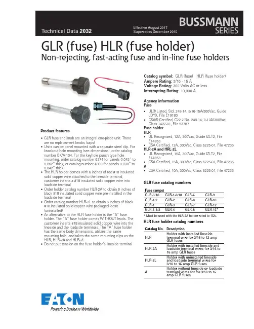
Product features •UL® Listed, Std. 248-14, 3/16-15A/300Vac, Guide JDYX, File E19180•CSA® Certified, C22.2 No. 248.14, 0-10A/300Vac, Class 1422-01, File 53787Fuse holderHLR•UL Recognized, 12A, 300Vac, Guide IZLT2, File E14853•CSA Certified, 12A, 300Vac, Class 6225-01, File 47235 HLR-2A and HRL-2L•UL Recognized, 15A, 300Vac, Guide IZLT2, File E14853•CSA Certified, 15A, 300Vac, Class 6225-01, File 47235 A•CSA Certified, 10A, 300Vac, Class 6225-01, File 47235G LR(fuse) HL R (fuse holder)Non-rejecting, fast-acting fuse and in-line fuse holders•GLR fuse and knob are an integral one-piece unit. There are no replacement knobs (caps)•Units can be panel mounted with a separate steel clip. For knockout hole mounting (see dimensions), order catalog number BK/A-104. For the keyhole punch type hole mounting, order catalog number 6374 for panels 0.043” to 0.062” thick, or catalog number 4909 for panels 0.030” to 0.042” thick.•The HLR holder comes with 6 inches of red #18 insulated solid copper wire attached to the lineside terminal, customer inserts a #18 insulated solid copper wire into loadside terminal•Order holder catalog number HLR-2A to obtain 6 inches of black #18 insulated solid copper wire pre-installed in the loadside terminal•Order catalog number HLR-2L to obtain 6 inches of black #18 insulated solid copper wire packaged loose (uninstalled)•An alternative to the HLR fuse holder is the “A” fuse holder. The “A” fuse holder comes WITHOUT leads. The customer inserts #18 insulated solid copper wire into the lineside and the loadside terminals. The “A” fuse holder has the same body dimensions, utilizes the same mounting hole, and takes the same mounting clips as the HLR, HLR-2A and HLR-2L•Do not put tension on the fuse holder’s lineside terminal Catalog symbol:G LR (fuse) HL R (fuse holder) Ampere Rating:3/16-15 AVoltage Rating: 300 Volts AC or less Interrupting Rating: 10,000 AAgency informationFuseGLR fuse catalog numbersFuse (amps)GLR-3/16GLR-1-6/10GLR-5GLR-9 GLR-1/2GLR-2GLR-6GLR-10 GLR-1GLR-3GLR-7GLR-12 GLR-1-1/2GLR-4GLR-8GLR-15* *Must be used with the HLR-2A holder rated to 15A. HLR fuse holder catalog numbersCatalog No. DescriptionHLR Holder with installed linseide terminal wire for 3/16 to 12 amp GLR fusesHLR-2A Holder with installed lineside and loadside terminal wires for 3/16 to 15 amp GLR fusesHLR-2L Holder with uninstalled lineside and loadside terminal wires for 3/16 to 15 amp GLR fusesA Holder without lineside or loadside termianl wires for for 3/16 to 15 amp GLR fusesEatonElectronics Division 1000 Eaton Boulevard Cleveland, OH 44122United States/electronics © 2017 EatonAll Rights Reserved Printed in USAPublication No. 2032 BU-MC15051 August 2017Eaton is a registered trademark.All other trademarks are property of their respective owners.Life Support Policy: Eaton does not authorize the use of any of its products for use in life support devices or systems without the express written approval of an officer of the Company. Life support systems are devices which support or sustain life, and whose failure to perform, when properly used in accordance with instructions for use provided in the labeling, can be reasonably expected to result in significant injury to the user.Eaton reserves the right, without notice, to change design or construction of any products and to discontinue or limit distribution of any products. Eaton also reserves the right to change or update, without notice, any technical information contained in this bulletin.GLR (fuse) HLR (fuse holder)Non-rejecting, fast-acting fuse and in-line fuse holdersTechnical Data 2032Effective August 2017Dimensions - in (mm):GLR fuseKeyhole punchKnockout holeHLR fuse holderMounting holesT i m e i n s e c o n d s0.1110100200Time-current characteristic curves — average meltCurrent in amps。
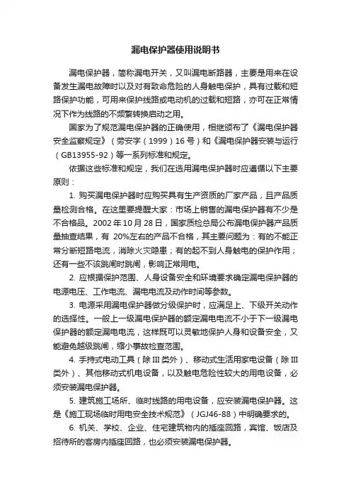
漏电保护器使用说明书漏电保护器,简称漏电开关,又叫漏电断路器,主要是用来在设备发生漏电故障时以及对有致命危险的人身触电保护,具有过载和短路保护功能,可用来保护线路或电动机的过载和短路,亦可在正常情况下作为线路的不频繁转换启动之用。
国家为了规范漏电保护器的正确使用,相继颁布了《漏电保护器安全监察规定》(劳安字(1999)16号)和《漏电保护器安装与运行(GB13955-92)等一系列标准和规定。
依据这些标准和规定,我们在选用漏电保护器时应遵循以下主要原则:1. 购买漏电保护器时应购买具有生产资质的厂家产品,且产品质量检测合格。
在这里要提醒大家:市场上销售的漏电保护器有不少是不合格品。
2002年10月28日,国家质检总局公布漏电保护器产品质量抽查结果,有20%左右的产品不合格,其主要问题为:有的不能正常分断短路电流,消除火灾隐患;有的起不到人身触电的保护作用;还有一些不该跳闸时跳闸,影响正常用电。
2. 应根据保护范围、人身设备安全和环境要求确定漏电保护器的电源电压、工作电流、漏电电流及动作时间等参数。
3. 电源采用漏电保护器做分级保护时,应满足上、下级开关动作的选择性。
一般上一级漏电保护器的额定漏电电流不小于下一级漏电保护器的额定漏电电流,这样既可以灵敏地保护人身和设备安全,又能避免越级跳闸,缩小事故检查范围。
4. 手持式电动工具(除III类外)、移动式生活用家电设备(除III 类外)、其他移动式机电设备,以及触电危险性较大的用电设备,必须安装漏电保护器。
5. 建筑施工场所、临时线路的用电设备,应安装漏电保护器。
这是《施工现场临时用电安全技术规范》(JGJ46-88)中明确要求的。
6. 机关、学校、企业、住宅建筑物内的插座回路,宾馆、饭店及招待所的客房内插座回路,也必须安装漏电保护器。
7. 安装在水中的供电线路和设备以及潮湿、高温、金属占有系数较大及其他导电良好的场所,如机械加工、冶金、纺织、电子、食品加工等行业的作业场所,以及锅炉房、水泵房、食堂、浴室、医院等场所,必须使用漏电保护器进行保护。

TE3001电气火灾监控设备安装使用说明书(Ver.1.0,2018.10)前言电气火灾监控系统是深圳市泰和安科技有限公司为适应工程设计需要而开发的一套系统。
电气火灾监控系统依据GB 50016-2014《建筑设计防火规范》、GB 50116-2013《火灾自动报警系统设计规范》、GB 25506-2010《消防控制室通用技术要求》、GB 14287.1-2014《电气火灾监控系统第1部分:电气火灾监控设备》标准要求而设计,为室内使用设备。
TE3001电气火灾监控设备采用壁挂式结构,模块式设计,具有功能强、可靠性高、配置灵活的特点。
系统采用128×64点汉字液晶显示,全汉字操作及提示界面。
打印机可打印系统所有报警、故障及各类操作的汉字信息。
最大容量为100个地址点,具有全面的现场编程能力。
本安装使用说明书应由专人负责,妥善保管,以备日后查用。
目录1 概述 (4)2 功能 (4)3 特点 (4)4 技术指标 (4)5 配置说明及结构特征 (5)5.1 外观及面板说明 (5)5.2 内部结构说明 (6)5.3外接端子说明 (7)5.4布线要求 (7)5.5接线说明 (7)6 安装与调式 (8)6.1 开箱检查 (8)6.2 监控设备内部配置及连接状况检查 (8)6.3 开机前检查 (8)6.4 安装方法 (8)6.5 外部设备检查 (9)6.6 调试 (9)7 操作说明 (9)7.1 键盘介绍 (9)7.2 键盘的解锁与锁键盘 (9)7.3进入主菜单 (10)7.4查询实时信息 (10)7.4.1报警信息查询 (10)7.4.2联动信息查询 (10)7.4.3故障信息查询 (11)7.4.4屏蔽信息查询 (11)7.5记录查询 (11)7.6登录查询 (11)7.6.1总线部件 (11)7.6.2回路登录信息 (12)7.6.3重新登录 (12)7.7屏蔽操作 (12)7.8用户操作 (13)7.8.1时间设置 (13)7.8.2打印设置 (13)7.8.3系统工作模式 (13)7.8.4密码设置 (13)7.8.5按键声设置 (14)7.8.6联动模式 (14)7.9管理员操作 (14)7.9.1分机网络设置 (14)7.9.2总线设备配置 (15)7.9.3离线设置 (16)7.9.4联动编程 (16)7.9.5恢复出厂设置 (16)7.10复位 (17)7.11查询 (17)7.12自检 (17)7.13 消音 (17)7.14 操作级别设置 (17)8 常见故障及维修 (17)9 日常维护及保修 (18)10 打印机使用说明 (18)请联系我们 (19)1 概述TE3001型电气火灾监控设备(简称监控设备)是根据国家标准GB14287.1-2014《电气火灾监控系统第1部分:电气火灾监控设备》,针对电气火灾进行实时监控的全新系统。
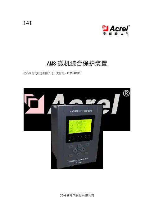
141AM3微机综合保护装置安科瑞电气股份有限公司,艾优花,137****8831安装使用说明书V1.30安科瑞电气股份有限公司申明版权所有,未经本公司之书面许可,此手册中任何段落,章节内容均不得被摘抄、拷贝或以任何形式复制、传播,否则一切后果由违者自负。
本公司保留一切法律权利。
本公司保留对本手册所描述之产品规格进行修改的权利,恕不另行通知。
订货前,请垂询当地代理商以获悉本产品的最新规格。
目录第一章装置介绍 01 概述 02功能配置 02.1 保护功能 02.2 测控功能 (1)第二章技术参数 (1)1 额定参数 (1)1.1 工作电源 (1)1.2信号电压输入 (1)1.3信号电流输入 (1)2 技术指标 (1)2.1 测量元件特性 (1)2.2 接点容量 (1)3 使用环境 (1)4 电气安全性 (2)4.1 绝缘电阻 (2)4.2 介质强度 (2)4.3 冲击电压 (2)5 电磁兼容性 (2)6 机械性能 (2)6.1 振动(正弦) (2)6.2 冲击 (2)6.3 碰撞 (2)第三章装置操作说明 (3)1 前面板说明 (3)2 按键说明 (3)3 菜单说明 (4)3.1 菜单结构 (4)3.2幅值显示 (5)3.3 DI显示 (6)3.4 遥测显示 (6)3.5 遥信显示 (6)3.6 定值显示 (6)3.7 版本显示 (6)3.8 时钟设置 (7)3.9定值修改 (7)3.10 装置地址修改 (7)3.11 通讯设置 (8)3.12 软压板设置 (8)3.13 遥控操作 (8)3.14 出错报告 (8)3.15 事件记录 (8)3.16 调试功能(制造商使用,略) (9)第四章安装与接线 (9)1 外形及开孔尺寸 (9)2 装置背部端子图及接线方法 (10)2.1 背部端子 (10)2.2 接线方法 (10)2.2.2 PT测控接线 (12)3.防跳模块 (12)第五章维护及其他问题处理 (13)附录A 装置出厂默认定值表 (13)附录B 装置事件记录清单 (15)第一章装置介绍1 概述AM3系列微机综合保护装置,集保护、测量、控制功能于一体,适用于10kV 及以下电压等级的配电线路和变压器保护,体积小巧,就地安装于中置柜、环网柜等,应用领域覆盖电力、水利、交通、石油、化工、煤炭、冶金等行业。
431AFDD-32型电弧故障保护电器安装使用说明书V1.0江苏安科瑞电器制造有限公司Jiangsu Acrel Electric MFG.CO.,Ltd.申明版权所有,未经本公司之书面许可,此手册中任何段落、章节内容均不得摘抄、拷贝或以任何形式复制、传播,否则一切后果由违者自负。
本公司保留一切法律权利。
本公司保留对本手册所描述之产品规格进行修改的权利,恕不另行通知。
订货前,请垂询当地代理商以获悉本产品的新规格。
目录1概述 (1)2产品型号 (1)3技术参数 (1)4产品特性 (2)5安装与接线 (2)5.1外形及安装尺寸(单位mm) (2)5.2安装方式 (2)5.3接线说明 (2)6指示灯定义及按键操作 (2)6.1测量项目说明 (2)6.2指示灯定义 (2)6.3按键操作 (3)6.4产品使用说明 (3)7注意事项 (3)1概述AFDD-32型电弧故障保护电器(以下简称“保护器”)由小型断路器、脱扣结构、电弧检测模块组成,具有短路保护、过载保护和电弧故障保护的功能,用于额定电流32A 及以下的交流电路中。
线路绝缘层老化、破损及空气潮湿都容易产生故障电弧现象,保护器中的电弧故障保护单元能检测和辨别到线路中的串联电弧故障、并联电弧故障及接地电弧故障。
当检测到线路中存在故障电弧时会自动脱扣,切断电源,从而预防电气火灾的发生。
产品符合GB/T31143-2014《电弧故障保护电器(AFDD)的一般要求》。
2产品型号3技术参数壳架等级产品类型:安科瑞电弧故障保护电器4产品特性电弧故障保护电器动作判别的极限,分断时间极限值如下表所示。
试验电弧电流3A6A13A20A40A63A(有效值)最大分断时间1s0.5s0.25s0.15s0.12s0.12s试验电弧电流是试验电路中发生燃弧前的预期电流5安装与接线5.1外形及安装尺寸(单位mm)5.2安装方式35mm导轨安装,可加固定端子进行固定。
5.3接线说明6指示灯定义及按键操作6.1测量项目说明可检测电路中的故障电弧、短路和过载,当输入信号达到报警设置时,发出光报警并且切断电源。
428ARD3M智能电动机保护器使用说明书V1.2安科瑞电气股份有限公司ACREL Co.,Ltd申明版权所有,未经本公司之书面许可,此手册中任何段落,章节内容均不得被摘抄、拷贝或以任何形式复制、传播,否则一切后果由违者自负。
本公司保留一切法律权利本公司保留对本手册所描述之产品规格进行修改的权利,恕不另行通知。
订货前,请垂询当地代理商以获悉本产品的最新规格。
目录1、概述 (1)2、产品特点 (1)3、型号说明 (2)4、主要参数 (3)5、外形尺寸及安装 (5)6、保护功能说明 (12)7、功能设置与说明 (27)8、通讯设置与说明 (42)9、典型应用方案 (82)10、特色功能简介 (87)11、订货范例 (89)1、概述ARD3M智能电动机保护器(以下简称保护器)适用于额定电压至660V的低压电动机回路,集保护、测量、控制、通讯、运维于一体。
其完善的保护功能确保电动机安全运行,带有逻辑可编程功能,可以满足多种控制方式。
可选配不同通讯模块适应现场通讯需求。
该产品采用分体式结构,由主体、显示单元、互感器和选配的通讯模块组成,可适应各种柜体的安装。
产品执行标准:——GB14048.4-2010低压开关设备和控制设备第4-1部分:接触器和电动机起动器机电式接触器和电动机起动器(含电动机保护器);——JBT10736-2007低压电动机保护器。
2、产品特点■辅助电源类型可选,AC220V电源模块支持电源范围AC85-265V/DC100-300V,AC380V 电源模块支持电源范围AC/DC100-415V。
■支持基波和全波电力参数测量(U、I、P、Q、S、PF、F、EP、EQ),电压及电流不平衡度,电压、电流正序、负序、零序分量,三相电压相角,剩余电流,电压、电流2-63次分次谐波测量,分次谐波含有率及总谐波畸变率。
■保护功能包括过载反时限、过载定时限、接地、起动超时、漏电、欠载、断相、堵转、阻塞、短路、溢出、不平衡(电流、电压)、过功率、欠功率、过压、欠压、相序、温度、tE 时间、外部故障、起动次数限制、运行时间报警、故障次数报警。
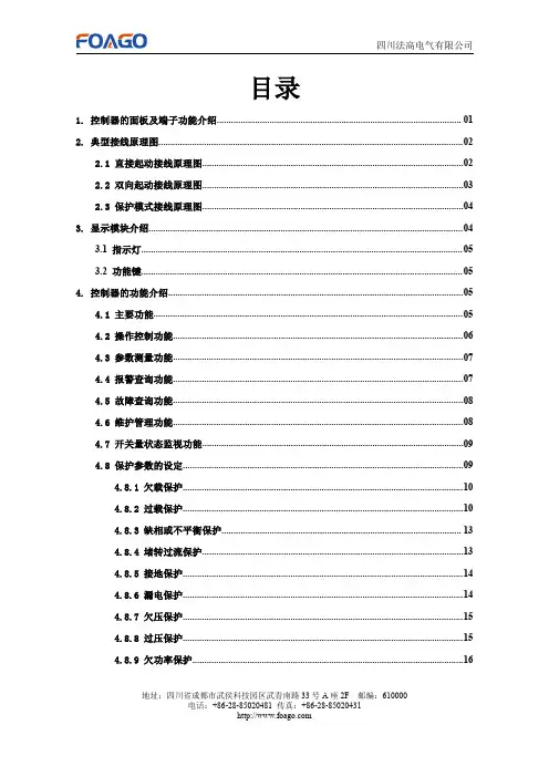
C K-300M低压电动机保护装置使用说明书APPLICATION INSTRUCTIONS____________________________________________________ 天水长开电子科技有限公司TIANSHUI CHANGKAI ELECTRONICS CO.,LTD目录1.装置简介 (5)1.1概述 (5)1.2 产品特点 (5)2技术指标 (6)2.1环境条件 (6)2.2辅助电源 (6)2.3额定参数 (6)2.4功率消耗 (6)2.5过载能力 (7)2.6保护定值误差 (7)2.7测量精度. (7)2.8继电器输出. (7)2.9开关量输入 (7)2.10通讯口 (8)2.11电气绝缘特性 (8)2.11.1介质强度 (8)2.11.2绝缘电阻 (8)2.11.3冲击电压 (8)2.11.4EMC特性 (8)2.11.4.1静电放电干扰 (8)2.11.4.3电快速瞬变脉冲群干扰 (8)2.11.4.4浪涌干扰 (8)2.11.4.5射频传导干扰 (8)2.11.4.6工频磁场干 (8)3功能原理 (9)3.1保护功能 (9)3.1.1保护动作特性 (9)3.1.2短路保护 (10)3.1.3堵转保护 (10)3.1.4定时限过负荷保护 (11)3.1.5反时限过负荷保护(热元件保护) (11)3.1.6接地保护 (13)3.1.7电流不平衡保护 (13)3.1.8断相保护 (14)3.1.9欠压保护 (15)3.1.10过压保护 (16)3.1.11tE时间保护 (17)3.1.12启动时间过长保护 (18)3.1.13工艺联锁跳闸 (19)3.1.14晃电自起动功能 (19)3.2测量功能 (21)3.3事件顺序记录(SO E) (21)3.4通讯功能 (21)3.5开出、开入功能 (22)3.5.1继电器输出(DO1~DO4 (22)3.5.2开关量输入(DI1~DI11) (23)3.6模拟量输入、模拟量输出功能 (23)3.6.1模拟量输入 (23)3.6.2模拟量输出(4—20mA) (23)3.7需要零序保护的低压电动机外接零序CT选用说明 (24)3.7.1外接零序CT与软件合成零序电流说明 (24)3.7.2零序CT要求 (24)3.7.3零序电流显示 (24)3.7.4保护整定 (25)3.7.5保护整定举例 (25)4安装和接线 (25)4.1安装 (25)4.1.1环境要求 (25)4.1.2安装 (25)4.1.3安装尺寸 (25)4.1.3.1一体式安装 (25)4.1.3.2分体式安装 (26)4.1.3.3专用小型穿心式CT-MT (26)4.2接线 (27)4.2.1端子接线(11DI4DO-AO,内置CT) (27)4.2.2端子接线(11DI4DO-AO,外置穿心CT) (29)4.2.3工作电源 (31)4.2.4电压电流输入接线 (31)4.2.5各种接线方式下的电压电流接线 (31)4.2.5.1电压直接接入,三相四线不带P T 带3CT(接线模式选“4线星形”) (31)4.2.5.2电压直接接入,三相三线不带P T,带3CT(接线模式选“三角形”) (32)4.2.5.3电压经P T接入,三相四线带3P T 带3CT(接线模式选“4线星形”) (32)4.2.5.4电压经P T接入,三相三线不带P T 带3CT(接线模式选“三角形”) (32)4.3典型接线图 (33)4.3.1保护模式 (33)4.3.2直接启动 (34)4.3.3自耦降压启动. (35)4.3.4星三角启动 (36)4.3.5正反向启动 (37)4.3.6典型应用 (38)5基本操作 (39)5.1开机 (39)5.2面板按键 (39)5.3测量显示模式 (40)5.3.1按键功能 (40)5.3.2显示说明 (41)5.4参数设置模式 (42)5.4.1按键操作 (42)5.4.2参数设置的内容说明 (42)5.4.3参数设置操作举例(见附录) (49)5.4.4设置短路保护操作举例(见附录) (49)5.5自动SOE弹出显示 (49)5.6状态指示 (50)5.6.1开入节点、开出继电器状态显示 (50)5.6.2运行指示 (50)6电动机的启动控制 (51)6.1启动方式分类 (51)6.2启动控制权限 (53)6.3各种启动控制下的接线 (54)6.3.1直接启动方式 (54)6.3.2自耦降压启动方式 (55)6.3.3星三角启动方式 (56)6.3.4正反转启动方式 (57)7装置调试与故障分析 (58)7.1装置调试 (58)7.2装置故障分析 (59)7.2.1无显示 (59)7.2.2装置上电后工作不正常 (59)7.2.3电压或电流读数不正确 (60)7.2.4功率或功率因数读数不正确,但电压和电流读数正确 (60)7.2.5不能正确操作断路器或操作信号不正确 (60)7.2.6开关量输入不正确 (60)7.2.7 RS-485通讯不正常 (60)8订货须知 (61)9售后服务承诺 (62)9.1新装置质量保证 (62)9.2装置升级 (62)9.3装置质保限制 (62)10附录:参数编程和设置短路保护设置 (63)1装置简介概述CK300M低压电动机保护测控装置是结合国际上电力自动化的发展趋势与国内电网特点而开发出来的,适用于低压380V系统,满足国内用户对低压电动机保护的需求。
漏电保护器使用说明书漏电保护器,简称漏电开关,又叫漏电断路器,主要是用来在设备发生漏电故障时以及对有致命危险的人身触电保护,具有过载和短路保护功能,可用来保护线路或电动机的过载和短路,亦可在正常情况下作为线路的不频繁转换启动之用。
国家为了规范漏电保护器的正确使用,相继颁布了《漏电保护器安全监察规定》(劳安字(1999)16号)和《漏电保护器安装与运行(GB13955-92)等一系列标准和规定。
依据这些标准和规定,我们在选用漏电保护器时应遵循以下主要原则:1. 购买漏电保护器时应购买具有生产资质的厂家产品,且产品质量检测合格。
在这里要提醒大家:市场上销售的漏电保护器有不少是不合格品。
2002年10月28日,国家质检总局公布漏电保护器产品质量抽查结果,有20%左右的产品不合格,其主要问题为:有的不能正常分断短路电流,消除火灾隐患;有的起不到人身触电的保护作用;还有一些不该跳闸时跳闸,影响正常用电。
2. 应根据保护范围、人身设备安全和环境要求确定漏电保护器的电源电压、工作电流、漏电电流及动作时间等参数。
3. 电源采用漏电保护器做分级保护时,应满足上、下级开关动作的选择性。
一般上一级漏电保护器的额定漏电电流不小于下一级漏电保护器的额定漏电电流,这样既可以灵敏地保护人身和设备安全,又能避免越级跳闸,缩小事故检查范围。
4. 手持式电动工具(除III类外)、移动式生活用家电设备(除III 类外)、其他移动式机电设备,以及触电危险性较大的用电设备,必须安装漏电保护器。
5. 建筑施工场所、临时线路的用电设备,应安装漏电保护器。
这是《施工现场临时用电安全技术规范》(JGJ46-88)中明确要求的。
6. 机关、学校、企业、住宅建筑物内的插座回路,宾馆、饭店及招待所的客房内插座回路,也必须安装漏电保护器。
7. 安装在水中的供电线路和设备以及潮湿、高温、金属占有系数较大及其他导电良好的场所,如机械加工、冶金、纺织、电子、食品加工等行业的作业场所,以及锅炉房、水泵房、食堂、浴室、医院等场所,必须使用漏电保护器进行保护。
164AIM-T300绝缘监测仪安装使用说明书V1.0安科瑞电气股份有限公司目录1概述 (1)2功能特点 (1)3型号说明 (1)5参考标准 (2)6安装与接线 (2)6.1外型和尺寸 (2)6.2安装方法 (3)6.3接线方法 (3)6.4注意事项 (4)7编程与使用 (4)7.1面板说明 (4)7.2LED指示说明 (5)7.3按键功能说明 (5)7.4按键操作说明 (5)8.通讯地址表 (8)9.典型应用 (9)9.1典型接线图 (9)AIM-T300绝缘监测仪1概述AIM-T300绝缘监测仪是安科瑞电气集多年电力仪表行业的设计经验,研究开发出来用于监测低压IT配电系统(又称不接地系统)对地绝缘状况的装置。
产品采用先进的微控制器技术,集成度高,体积小巧,安装方便,集智能化、数字化、网络化于一身。
装置具有绝缘故障预警、故障报警、事件记录等多种功能,可用于矿井、玻璃厂、电炉和试验设备、冶金厂、化工厂、爆炸危险场所、计算机中心以及应急电源等场所的IT系统中,实时监测IT系统对地的绝缘状况。
产品符合企业标准《IT系统绝缘监测仪》(Q/VDCL-26-2017)的规定要求。
2功能特点2.1具有对被监测IT系统对地绝缘电阻监测、故障预警及报警功能;2.2继电器报警输出、LED报警输出等多种故障指示功能;2.3采用先进的现场总线通讯技术,可与外接报警和显示仪、上位机管理终端通讯,实时监控IT系统的运行状况;2.4具有故障事件记录功能,能够记录故障发生的时间和故障类型,方便操作人员分析系统运行状况,及时消除故障。
2.5适用于交流、直流以及交直流混合IT系统的绝缘监测。
2.6自检功能。
可一键实现仪表硬件电路的故障自检。
2.7断线监测功能。
实时监测L1/L2与IT系统之间的接线连线状况以及PE/KE功能接地接线连线状况。
3型号说明例如:AIM-T300产品:绝缘监测仪应用场所:工业场所4技术参数5参考标准5.1IEC 61557-8-2007《交流1000V 和直流1500V 以下低压配电系统电气安全防护检测的试验、测量或监控设备第8部分:IT 系统用绝缘监测装置》;5.2GB/T 18286.24-2010/IEC 61326-2-4:2006《测量、控制和实验室用的电设备电磁兼容性要求第24部分:特殊要求符合IEC 61557-8的绝缘监控装置和符合IEC 61557-9的绝缘故障定位设备的试验配置、工作条件和性能判据》6安装与接线6.1外型和尺寸AIM-T300外形与安装尺寸(单位:mm )辅助电源电压AC85 (265V)电压范围系统电压AC0 (480V)频率50/60Hz 额定频率40…460Hz 绝缘监测绝缘电阻测量范围1k-5M Ω输出继电器输出预警、报警预警、报警值范围10k —5M Ω环境工作温度-10—+55℃响应时间(Ce=1uF)<6s存储温度-20—+70℃测量电压<20V 相对湿度5%-95%,不结露允许系统泄漏电容<150uF 海拔高度≤2500m 内部参数测量电流<170uA通讯RS485接口,Modbus-RTU 协议内部直流阻抗≥120k Ω额定冲击电压/污染等级8kV/Ⅲ功耗<8WEMC 电磁兼容/电磁辐射符合IEC61326-2-4后视图侧视图正视图上图依次为嵌入式安装的绝缘监视仪AIM-T300的后视图、侧视图与正视图。