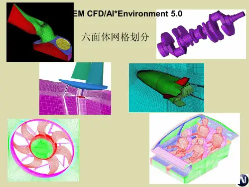
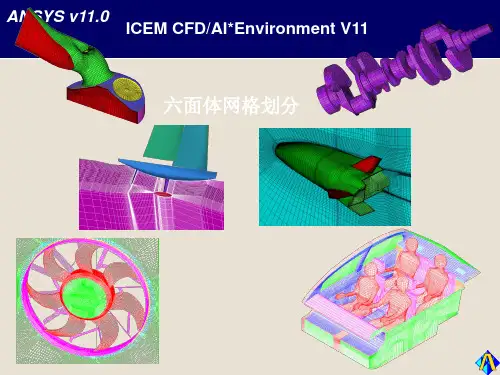
六面体网格划分教程2014-2-21
- 格式:pptx
- 大小:3.62 MB
- 文档页数:37
虽说是ansys网格划分,但是同时也适用于其他的软件,因为网格生成思想是一样的。
1、面映射网格划分(map)需满足以下条件:1)该面必须是3或4条边;面的对边必须划分为相同数目的单元或与一个过渡形状网格的划分匹配。
2)该面如果有三条边,则划分的单元必须为偶数且各边单元数相等。
3)网格划分必须设置为映射网格,结果得到全部四边形网格单元或三角形单元的映射网格,依赖于当前单元类型和单元形状设置。
如果变的数目多于4条,可以通过合并或连结线使面中连接线的数目减少到4条。
建议采用AMAP替代连接线,对拾取面的3或4个角点对面进行映射网格划分。
2、体映射网格划分(vmap)需满足条件:1)该体的外形应为块状(6个面)、楔形(5个面)或四面体。
2)体的对边必须划分相同的单元数或分割符合过渡网格形式适用于六面体网格划分。
3)如果体是棱柱或四面体,三角形面上的单元分割数必须是偶数。
组成体的面数超过上述条件限制时,需减少面数以进行映射网格划分。
可以对面进行加或连接操作,如果连接面有交界线,则线必须连接在一起,必须连接面后连接线。
3、体扫掠方法(VSWEEP)可以从一边界面网格扫掠贯穿整个体(该体必须存在且未划分网格)生成体单元。
如果源面网格有四边形网格组成,则生成六面体网格。
如果面由三角形网格组成,则生成楔形单元。
如果面有三角形和四边形组成,则体由楔形和六面体共同填充。
==============================个人总结==================================同时划分体单元的还有(VROTAT,VEXT,VOFFST,VDRAG),这些划分方式需要先建立一个已划分网格的面,然后利用该面进行旋转、拉伸、偏移等。
很多时候,我们需要将一个体进行切割,分成许多个适合划分的体,切割的技巧很多,以后慢慢的再谈。
ansys建模计算-常用单元和材料类型土木计算过程中常用的单元和材料类型!一、单元(1)link(杆)系列:link1(2D)和link8(3D)用来模拟珩架,注意一根杆划一个单元。
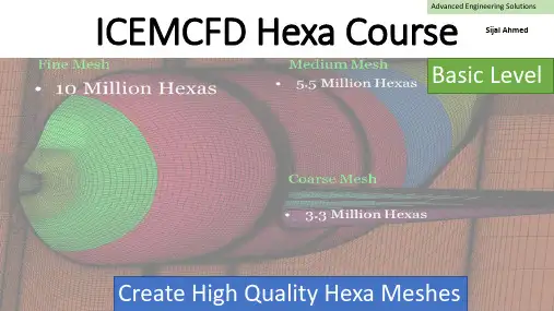
Advanced Engineering Solutions ICEMCFD Hexa Course Sijal AhmedBasic Level Create High Quality Hexa MeshesLecture 3 : Hexa MeshingSee DemoVertexEdgeFaceBlockPointCurveSurfaceVolume•Vertex color coding–Red →Point –Green →Curve –Black →Surface –Cyne →Internal•Edge color coding–Green →Curve –Black →Surface –Cyan →InternalCreate Block•3d bounding box •2d surface blocking •2d planner•3D block from vertices/faces ▪Hexa▪Quarter O-grid▪Degenerate or prism •2D block from verticesDegenerate or prism from 6 verticesQuarter O-grid from 6 verticesHexa from 8 verticesHexa from two facesExtrude Face(s)•Interactive•Select face and MMB whereyou want block•Fixed distance•Specify distance in normaldirection•Along the curve•Select curve and its endwhere you want to end theblockNumber of layers = 530 deg twist2d to 3d blocking •Translation•Rotation✓Choose origin✓Choose axis✓You can also create newparts from points and curvesAssociation•Vertex to point, curve or surface.•Edge to curve or surface.•Face to surface or part.•Edge color coding–Green →Curve –Black →Surface –Cyan →Internal•Vertex color coding–Red →Point –Green →Curve –Black →Surface –Cyne →InternalAll edges are associatedNo AssociationEach edge is associatedto corresponding curveO-GridFull O-GridMesh qualityHow to create O-gridFull O-gridHalf O-gridQuarter O-gridMerge VerticesPropagate MergeSelection of Blocks and Edge for CollapseSide 2 (head of arrow) params17 meshing laws curves/parts to edgesLinked bunchingScale sizes and refinementand refinement.Fraction are allowed whenyou want to coarse themeshfor refinementSelected blockFluent 1:2 RefinementCFX : 1 : 3 RefinementSplit Block •You can use following options:•Screen select•Prescribed point (most commonly used option)•Relative (on scale of 0-1, e.g. 0.5 implies 50% ofedge length)•Absolute (provide distance in units, e.g. in metersof length)•Hidden blocks•Extend split•Split on diagonal edge of O-grid will createanother o-Grid.Without splitMove Vertex•The following options are available for moving vertices:▪Move Vertex▪Set Location ▪Align Vertices ▪Align Vertices In-line ▪Set Edge Length ▪Move Face Vertices •You cannot move red vertex unless its association is changed•Vertex in green color can only slide along curve.•Vertex in black color can only slide over surface, if it is visible.•Vertex in cyne can move along the direction set by edge. •Vertex color coding–Red →Point–Green →Curve–Black →Surface–Cyne →InternalThe following options areavailable for editing block o Unsplit EdgeoLink Edge (link shape of one edge to other edge)o Unlink Edgeo Change Edge Split Type 17Source edge Target edgeMesh quality imporovedEdit Block•Most important options:→Modify O-Grid : Rescale Ogrid & reset Ogrid orthogonality →Modify block →Make periodic (use it with SetupMake periodic option •Use opposite vertices •Any subsequent split operation will make new vertices periodic too. •On axis choose same vertex twicePeriodic vertices▪Translate Blocks▪Rotate Blocks▪Mirror Blocks▪Scale Blocks▪Copy Periodic Blocking ▪Translate and RotateDelete Block•The Delete Block option allows you to delete the blocks from the topologyMonday, April 1, 201920Lecture 4 -Hexa Mesh & BlockingChecking Quality•Using the Quality Histogram–Determinant•Measurement of element deformation (squareness)•Most solvers accept > 0.1•Shoot for > 0.2–Angle•Element minimum internal angles•Shoot for >18 degrees–Aspect ratio–Volume–Warpage•Shoot for < 45 degrees–Many more metricsMonday, April 1, 201921Lecture 4 -Hexa Mesh & Blocking You can display elements in a given range byselecting the histogram barPre-Mesh Smooth & Check Blocks•Following options are available for Pre-Mesh smooth:–Quality –Orthogonality –Multi-block•Following options are available for check blocks:–Run Check/Fix–Fix Inverted Blocks etc。

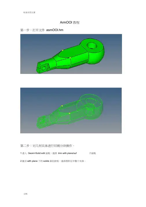
ArmOOl 教程第一步:打开文件asmOOl.hm第二步:对几何实体进行切割分块操作。
1 进入Geom>Solid edit 面板,选择trim with plane/suf 子面板2激活with plane 下的solids黄色按钮,选择图形区中整个实体。
p pnpm Irrrirn-r3激活下面的绿色N1按钮,并如图依次选择N1、N2、N3、B这四个点-£ fij Xi Tnpi # :』i 中* -电卡岂创L艸4点击trim,将实体切割成为上下对称的两个体。
Model Irilo. E^ajfhtOI Jwf'r tin wth nQidffs广tin Hith Ines trlnwiTip Eme^sulr merge广dnechi『beolvHiisolkfe▼J詢血I W|!5Llff旨| |4 |厂凶郎W<un別t ln^…Il■TBjEb | r infflvuih nodes广Inm rtili luesFt Inn * 旳p sne/EU^ rfnei^er di^nu nr ti(Ki|凹「is Jflh輝・* G* •"名*>>C«np>J!?I応lidfe5激活with plane 下的solids黄色按钮,选择切割好的上半部分实体。
6激活线面的N1绿色按钮,如图依次选择N1、N2、N3这三个点。
7点击trim,将这上半部分实体切割成左右对称的两个实体。
第三步:删除多余实体和临时节点1点击F2快接键,进入Delete 面板。
2激活黄色的solids按钮,并勾选delete bounding surfs 。
在图形区中选择下半部分实体和上边的左半部分实体。
3点击delete entity ,删除掉多余的实体。
4进入Geom>temp node 面板,点击绿色的clear all按钮,删除掉多余的临时节点。


工具栏模型树
状态栏
主操作命令栏
主命令面板菜单栏
图形显示区
旋转——spin
或者沿线拉伸——line drag
——elem offset 或者沿线拉伸——line drag
linear solid Solid Map
4
输入名字
或者F12
6
或者F4
按下鼠标左键,放
至弧线直至变亮
选择三点
圆心
7
按住“Shift”键,用左键框
选(右键去掉多余的选择)
注意旋转方向
按“V”键进入视图管理
8
沿此线拉伸
与另一端对应
左键增加,右键减少
10
11
直接选择相应的collector ,或者选择元素
自动创建一个“^faces ”的collector
可通过“by face”选择
节点要对应
选择之后,先复制
14
依次选择点
单独显示体网格
或者“Shift”+F3可按“D”键进入
display面板
调整容差,但最好不要
超过网格尺寸的20%
构思……构思&构思很重要,只要一路下
去节点能重合,基本上说明构思成功!。