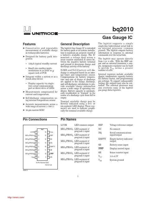
Features➤Conservative and repeatable measurement of available charge in rechargeable batteries ➤Designed for battery pack inte-gration-120µA typical standby current -Small size enables imple-mentations in as little as 12square inch of PCB➤Integrate within a system or as a stand-alone device-Display capacity via single-wire serial communication port or direct drive of LEDs➤Measurements compensated for current and temperature ➤Self-discharge compensation us-ing internal temperature sensor ➤Accurate measurements across a wide range of current (>500:1)➤16-pin narrow SOICGeneral DescriptionThe bq2010Gas Gauge IC is intended for battery-pack or in-system installa-tion to maintain an accurate record of a battery's available charge.The IC monitors a voltage drop across a sense resistor connected in series be-tween the negative battery terminal and ground to determine charge and discharge activity of the battery .NiMH and NiCd battery self-dis-charge is estimated based on an inter-nal timer and temperature pensations for battery tempera-ture and rate of charge or discharge are applied to the charge,discharge,and self-discharge calculations to pro-vide available charge information across a wide range of operating con-ditions.Battery capacity is automati-cally recalibrated,or “learned,”in the course of a discharge cycle from full to empty .Nominal available charge may be directly indicated using a five-or six-segment LED display .These seg-ments are used to indicate graphi-cally the nominal available charge.The bq2010supports a simple single-line bidirectional serial link to an external processor (common ground).The bq2010outputs battery information in response to external commands over the serial link.The bq2010may operate directly from 3or 4cells.With the REF out-put and an external transistor,a sim-ple,inexpensive regulator can be built to provide V CC across a greater number of cells.Internal registers include available charge,temperature,capacity ,battery ID,battery status,and programming pin settings.To support subassembly testing,the outputs may also be con-trolled.The external processor may also overwrite some of the bq2010gas gauge data registers.1LCOMLED common outputSEG 1/PROG 1LED segment 1/program 1input SEG 2/PROG 2LED segment 2/program 2input SEG 3/PROG 3LED segment 3/program 3input SEG 4/PROG 4LED segment 4/program 4input SEG 5/PROG 5LED segment 5/program 5input SEG 6/PROG 6LED segment 6/program 6input1PN201001.eps16-Pin Narrow SOIC234 5678161514131211109V CC REF NC DQ EMPTY SB DISP SRLCOMSEG 1/PROG 1SEG 2/PROG 2SEG 3/PROG 3SEG 4/PROG 4SEG 5/PROG 5SEG 6/PROG 6V SSREF Voltage reference output NC No connectDQ Serial communications input/outputEMPTY Empty battery indicator outputSB Battery sense input DISP Display control input SR Sense resistor input V CC 3.0–6.5V V SSSystem groundbq2010Pin Connections Pin Names4/95 DGas Gauge ICPin DescriptionsLCOM LED common outputOpen-drain output switches V CC to sourcecurrent for the LEDs.The switch is off dur-ing initialization to allow reading of the softpull-up or pull-down program resistors.LCOM is also high impedance when the dis-play is off.SEG1–SEG6LED display segment outputs(dual func-tion with PROG1–PROG6)Each output may activate an LED to sink the current sourced from LCOM.PROG1–PROG2Programmed full count selection inputs (dual function with SEG1–SEG2)These three-level input pins define the pro-grammed full count(PFC)thresholds de-scribed in Table2.PROG3–PROG4Gas gauge rate selection inputs(dual function with SEG3–SEG4)These three-level input pins define the scale factor described in Table2.PROG5Self-discharge rate selection(dual func-tion with SEG5)This three-level input pin defines theselfdischarge compensation rate shown in Ta-ble1.PROG6Display mode selection(dual function with SEG6)This three-level pin defines the display op-eration shown in Table1.NC No connectSR Sense resistor inputThe voltage drop(V SR)across the sense re-sistor R S is monitored and integrated overtime to interpret charge and discharge activ-ity.The SR input is tied to the high side ofthe sense resistor.V SR<V SS indicates dis-charge,and V SR>V SS indicates charge.Theeffective voltage drop,V SRO,as seen by thebq2010is V SR+V OS(see Table5).DISP Display control inputDISP high disables the LED display.DISPtied to V CC allows PROG X to connect directlyto V CC or V SS instead of through a pull-up orpull-down resistor.DISP floating allows theLED display to be active during discharge orcharge if the NAC registers update at a rateequivalent to|V SRO|≥4mV.DISP low acti-vates the display.See Table1.SB Secondary battery inputThis input monitors the single-cell voltagepotential through a high-impedance resis-tive divider network for end-of-dischargevoltage(EDV)thresholds,maximum chargevoltage(MCV),and battery removed.EMPTY Battery empty outputThis open-drain output becomes high-impedanceon detection of a valid end-of-discharge voltage(V EDVF)and is low following the next applicationof a valid charge.DQ Serial I/O pinThis is an open-drain bidirectional pin.REF Voltage reference output for regulatorREF provides a voltage reference output foran optional micro-regulator.V CC Supply voltage inputV SS Ground2bq2010Functional DescriptionGeneral OperationThe bq2010determines battery capacity by monitoring the amount of charge input to or removed from a re-chargeable battery.The bq2010measures discharge and charge currents,estimates self-discharge,monitors the battery for low-battery voltage thresholds,and compen-sates for temperature and charge/discharge rates.The charge measurement derives from monitoring the voltage across a small-value series sense resistor between the negative battery terminal and ground.The available bat-tery charge is determined by monitoring this voltage over time and correcting the measurement for the environ-mental and operating conditions.Figure1shows a typical battery pack application of the bq2010using the LED display capability as a charge-state indicator.The bq2010can be configured to display capacity in either a relative or an absolute display mode.The relative display mode uses the last measured dis-charge capacity of the battery as the battery“full”refer-ence.The absolute display mode uses the programmed full count(PFC)as the full reference,forcing each seg-ment of the display to represent a fixed amount of charge.A push-button display feature is available for momentarily enabling the LED display.The bq2010monitors the charge and discharge currents as a voltage across a sense resistor(see R S in Figure1).A filter between the negative battery terminal and theSR pin may be required if the rate of change of the bat-tery current is too great.3bq2010Figure 1. Battery Pack Application Diagram—LED DisplayVoltage ThresholdsIn conjunction with monitoring V SR for charge/discharge currents,the bq2010monitors the single-cell battery potential through the SB pin.The single-cell voltage potential is determined through a resistor/divider net-work according to the following equation:RB RB N 121=−where N is the number of cells,RB 1is connected to the positive battery terminal,and RB 2is connected to the negative battery terminal.The single-cell battery volt-age is monitored for the end-of-discharge voltage (EDV)and for maximum cell voltage (MCV).EDV threshold levels are used to determine when the battery has reached an “empty”state,and the MCV threshold is used for fault detection during charging.Two EDV thresholds for the bq2010are fixed at:V EDV1(early warning) = 1.05VV EDVF (empty) = 0.95VIf V SB is below either of the two EDV thresholds,the as-sociated flag is latched and remains latched,indepen-dent of V SB ,until the next valid charge.EDV monitoring may be disabled under certain conditions as described in the next paragraph.During discharge and charge,the bq2010monitors V SR for various thresholds.These thresholds are used to compensate the charge and discharge rates.Refer to the count compensation section for details.EDV monitoring is disabled if V SR ≤-250mV typical andresumes second after V SR >-250mV .EMPTY OutputThe EMPTY output switches to high impedance when V SB <V EDVF and remains latched until a valid charge occurs.The bq2010also monitors V SB relative to V MCV ,2.25V .V SB falling from above V MCV resets the device.ResetThe bq2010recognizes a valid battery whenever V SB is greater than 0.1V typical.V SB rising from below 0.25V or falling from above 2.25V resets the device.Reset can also be accomplished with a command over the serial port as described in the Reset Register section.TemperatureThe bq2010internally determines the temperature in 10°C steps centered from -35°C to +85°C.The tempera-ture steps are used to adapt charge and discharge rate compensations,self-discharge counting,and availablecharge display translation.The temperature range is available over the serial port in 10°C increments as shown below:Layout ConsiderationsThe bq2010measures the voltage differential between the SR and V SS pins.V OS (the offset voltage at the SR pin)is greatly affected by PC board layout.For optimal results,the PC board layout should follow the strict rule of a single-point ground return.Sharing high-current ground with small signal ground causes undesirable noise on the small signal nodes.Additionally:nThe capacitors (SB and V CC ) should be placed asclose as possible to the SB and V CC pins, respectively,and their paths to V SS should be as short as possible.A high-quality ceramic capacitor of 0.1µf is recommended for V CC .nThe sense resistor capacitor should be placed as close as possible to the SR pin.nThe sense resistor (R SNS ) should be as close as possible to the bq2010.4bq2010TMPGG (hex)Temperature Range0x < -30°C 1x -30°C to -20°C 2x -20°C to -10°C 3x -10°C to 0°C 4x 0°C to 10°C 5x 10°C to 20°C 6x 20°C to 30°C 7x 30°C to 40°C 8x 40°C to 50°C 9x 50°C to 60°C Ax 60°C to 70°C Bx 70°C to 80°C Cx> 80°CGas Gauge OperationThe operational overview diagram in Figure2illustrates the operation of the bq2010.The bq2010accumulates a measure of charge and discharge currents,as well as an estimation of self-discharge.Charge and discharge cur-rents are temperature and rate compensated,whereas self-discharge is only temperature compensated.The main counter,Nominal Available Charge(NAC), represents the available battery capacity at any given time.Battery charging increments the NAC register, while battery discharging and self-discharge decrement the NAC register and increment the DCR(Discharge Count Register).The Discharge Count Register(DCR)is used to update the Last Measured Discharge(LMD)register only if a complete battery discharge from full to empty occurs without any partial battery charges.Therefore,the bq2010adapts its capacity determination based on the actual conditions of discharge.The battery's initial capacity is equal to the Programmed Full Count(PFC)shown in Table2.Until LMD is updated, NAC counts up to but not beyond this threshold during subsequent charges.This approach allows the gas gauge to be charger-independent and compatible with any type of charge regime.st Measured Discharge(LMD)or learnedbattery capacity:LMD is the last measured discharge capacity of thebattery.On initialization(application of V CC or bat-tery replacement),LMD=PFC.During subsequentdischarges,the LMD is updated with the latestmeasured capacity in the Discharge Count Register(DCR)representing a discharge from full to belowEDV1.A qualified discharge is necessary for a ca-pacity transfer from the DCR to the LMD register.The LMD also serves as the100%reference thresh-old used by the relative display mode.2.Programmed Full Count(PFC)or initial bat-tery capacity:The initial LMD and gas gauge rate values are pro-grammed by using PROG1–PROG4.The PFC alsoprovides the100%reference for the absolute dis-play mode.The bq2010is configured for a given ap-plication by selecting a PFC value from Table2.The correct PFC may be determined by multiplyingthe rated battery capacity in mAh by the sense re-sistor value:Battery capacity (mAh)*sense resistor (Ω) =PFC (mVh)Selecting a PFC slightly less than the rated capac-ity for absolute mode provides capacity above thefull reference for much of the battery's life.5bq2010Figure 2. Operational OverviewExample:Selecting a PFC Value Given:Sense resistor =0.1ΩNumber of cells =6Capacity =2200mAh,NiCd battery Current range =50mA to 2A Absolute display mode Serial port only Self-discharge=Voltage drop resistor =5mV to 200mV Therefore:2200mAh *0.1Ω=220mVhSelect:PFC =33792counts or 211mVh PROG 1=float PROG 2=float PROG 3=float PROG 4=low PROG 5=float PROG 6=floatThe initial full battery capacity is 211mVh (2110mAh)until the bq2010“learns”a new capac-ity with a qualified discharge from full to EDV1.6bq2010PROG x Pro-grammed Full Count (PFC)PROG 4= LPROG 4= ZUnits 12PROG3 = H PROG3 = Z PROG3 = L PROG3=H PROG3 = Z PROG3 = L ---Scale =1/80Scale =1/160Scale =1/320Scale =1/640Scale =1/1280Scale =1/2560mVh/countH H 4915261430715476.838.419.2mVh H Z 4505656328214170.435.217.6mVh H L 4096051225612864.032.016.0mVh Z H 3686446123011557.628.814.4mVh Z Z 3379242221110653.026.413.2mVh Z L 3072038419296.048.024.012.0mVh L H 2764834617386.443.221.610.8mVh L Z 2560032016080.040.020.010.0mVh LL2252828214170.435.217.68.8mVh VSR equivalent to 2counts/sec.(nom.)904522.511.255.62.8mVTable 2. bq2010 Programmed Full Count mVh SelectionsNote:PROG 5and PROG 6states are independent.Table 1. bq2010 Programming3.Nominal Available Charge(NAC):NAC counts up during charge to a maximum value of LMD and down during discharge and self-discharge to0.NAC is reset to0on initializa-tion(PROG6=Z or low)and on the first valid charge following discharge to EDV1.NAC is set to PFC on initialization if PROG6=high.To prevent over-statement of charge during periods of overcharge, NAC stops incrementing when NAC=LMD.4.Discharge Count Register(DCR):The DCR counts up during discharge independent of NAC and could continue increasing after NAC has decremented to0.Prior to NAC=0(empty battery),both discharge and self-discharge in-crement the DCR.After NAC=0,only discharge increments the DCR.The DCR resets to0when NAC=LMD.The DCR does not roll over but stops counting when it reaches ffffh.The DCR value becomes the new LMD value on the first charge after a valid discharge to V EDV1if:No valid charge initiations(charges greater than 256NAC counts,where V SRO>V SRQ)occurred during the period between NAC=LMD and EDV1 detected.The self-discharge count is not more than4096 counts(8%to18%of PFC,specific percentage threshold determined by PFC).The temperature is≥0°C when the EDV1level is reached during discharge.The valid discharge flag(VDQ)indicates whether the present discharge is valid for LMD update. Charge CountingCharge activity is detected based on a positive voltage on the V SR input.If charge activity is detected,the bq2010 increments NAC at a rate proportional to V SRO and,if en-abled,activates an LED display if the rate is equivalent to V SRO>4mV.Charge actions increment the NAC after compensation for charge rate and temperature.The bq2010determines charge activity sustained at a continuous rate equivalent to V SRO>V SRQ.A valid charge equates to sustained charge activity greater than 256NAC counts.Once a valid charge is detected,charge counting continues until V SRO(V SR+V OS)falls below V SRQ.V SRQ is a programmable threshold as described in the Digital Magnitude Filter section.The default value for V SRQ is375µV.Discharge CountingAll discharge counts where V SRO<V SRD cause the NAC register to decrement and the DCR to increment.Ex-ceeding the fast discharge threshold(FDQ)if the rate is equivalent to V SRO<-4mV activates the display,if en-abled.The display becomes inactive after V SRO rises above-4mV.V SRD is a programmable threshold as described in the Digital Magnitude Filter section.The default value for V SRD is-300µV.Self-Discharge EstimationThe bq2010continuously decrements NAC and incre-ments DCR for self-discharge based on time and tempera-ture.The self-discharge count rate is programmed to be anominal*NAC,*NAC per day,or disabled as se-lected5.is the rate for a battery whose temperature is between20°–30°C.The NAC register can-not be decremented below0.Count CompensationsThe bq2010determines fast charge when the NAC up-dates at a rate of≥2counts/sec.Charge and discharge activity is compensated for temperature and charge/dis-charge rate before updating the NAC and/or DCR.Self-discharge estimation is compensated for temperature before updating the NAC or DCR.Charge CompensationTwo charge efficiency compensation factors are used for trickle charge and fast charge.Fast charge is defined asa rate of charge resulting in≥2NAC counts/sec(≥0.15Cto0.32C depending on PFC selections;see Table2).The compensation defaults to the fast charge factor until the actual charge rate is determined.Temperature adapts the charge rate compensation factors over three ranges between nominal,warm,and hot tem-peratures.The compensation factors are shown below.Discharge CompensationCorrections for the rate of discharge are made by adjust-ing an internal discharge compensation factor.The dis-charge compensation factor is based on the namically measured V SR.7bq2010ChargeTemperatureTrickle ChargeCompensationFast ChargeCompensation <30°C0.800.9530–40°C0.750.90> 40°C0.650.80The compensation factors during discharge are:Temperature compensation during discharge also takes place.At lower temperatures,the compensation factor in-creases by 0.05for each 10°C temperature step below 10°C.Comp.factor = 1.0 + (0.05*N)Where N =Number of 10°C steps below 10°C and -150mV <V SR <0.For example:T >10°C :Nominal compensation,N =00°C <T <10°C:N =1(i.e.,1.0becomes 1.05)-10°C <T <0°C:N =2(i.e.,1.0becomes 1.10)-20°C <T <-10°C:N =3(i.e.,1.0becomes 1.15)-20°C <T <-30°C:N =4(i.e.,1.0becomes 1.20)Self-Discharge CompensationTheis programmed for a nomi-nal rate **NAC per day ,or disabled.This is the rate a within the 20–30°C temperature range (TMPGG =6x).This rate varies across 8ranges from <10°C to >70°C,doubling with each higher temperature step (10°C).See Table 3.Digital Magnitude FilterThe bq2010has a programmable digital filter to elimi-nate charge and discharge counting below a set thresh-old.The default setting is -0.30mV for V SRD and +0.38mV for V SRQ .The proper digital filter setting can be calculated using the following equation.Table 4shows typical digital filter settings.V SRD (mV) = -45 / DMFV SRQ (mV) = -1.25*V SRDError SummaryCapacity InaccurateThe LMD is susceptible to error on initialization or if no updates occur.On initialization,the LMD value in-cludes the error between the programmed full capacity and the actual capacity .This error is present until a valid discharge occurs and LMD is updated (see the DCR description on page 7).The other cause of LMD er-ror is battery wear-out.As the battery ages,the meas-ured capacity must be adjusted to account for changes in actual battery capacity .A Capacity Inaccurate counter (CPI)is maintained and incremented each time a valid charge occurs (qualified by NAC;see the CPI register description)and is reset whenever LMD is updated from the DCR.The counter does not wrap around but stops counting at 255.The ca-pacity inaccurate flag (CI)is set if LMD has not been updated following 64valid charges.Current-Sensing ErrorTable 5illustrates the current-sensing error as a func-tion of V SR .A digital filter eliminates charge and dis-charge counts to the NAC register when V SRO (V SR +V OS )is between V SRQ and V SRD .Communicating With the bq2010The bq2010includes a simple single-pin (DQ plus re-turn)serial data interface.A host processor uses the in-terface to access various bq2010registers.Battery char-acteristics may be easily monitored by adding a single contact to the battery pack.The open-drain DQ pin on8bq2010Table 3. Self-Discharge CompensationApproximate V SR Threshold Discharge CompensationFactorEfficiency V SR > -150 mV 1.00100%V SR < -150 mV1.0595%DMF DMF Hex.V SRD (mV)V SRQ (mV)754B -0.600.7510064-0.450.56150 (default)96-0.300.38175AF -0.260.32200C8-0.230.28Table 4. Typical Digital Filter Settingsthe bq2010should be pulled up by the host system or may be left floating if the serial interface is not used.The interface uses a command-based protocol,where the host processor sends a command byte to the bq2010.The command directs the bq2010either to store the next eight bits of data received to a register specified by the command byte or to output the eight bits of data speci-fied by the command byte.The communication protocol is asynchronous mand and data bytes consist of a stream of eight bits that have a maximum transmission rate of 333bits/sec.The least-significant bit of a command or data byte is transmitted first.The protocol is simple enough that it can be implemented by most host processors using either polled or interrupt processing.Data input from the bq2010may be sampled using the pulse-width capture timers available on some microcontrollers.Communication is normally initiated by the host processor sending a BREAK command to the bq2010.A BREAK is detected when the DQ pin is driven to a logic-low state for a time,t B or greater.The DQ pin should then be returned to its normal ready-high logic state for a time,t BR .The bq2010is now ready to receive a command from the host processor.The return-to-one data bit frame consists of three distinct sections.The first section is used to start the transmission by either the host or the bq2010taking the DQ pin to a logic-low state for a period,t STRH,B .The next section is the actual data transmission,where the data should be valid by a period,t DSU ,after the negative edge used to startcommunication.The data should be held for a period,t DV ,to allow the host or bq2010to sample the data bit.The final section is used to stop the transmission by re-turning the DQ pin to a logic-high state by at least a peri-od,t SSU ,after the negative edge used to start communica-tion.The final logic-high state should be held until a peri-od,t SV ,to allow time to ensure that the bit transmission was stopped properly .The timings for data and break communication are given in the serial communication tim-ing specification and illustration sections.Communication with the bq2010is always performed with the least-significant bit being transmitted first.Figure 3shows an example of a communication se-quence to read the bq2010NAC register.bq2010 RegistersThe bq2010command and status registers are listed in Table 6and described below .Command Register (CMDR)The write-only CMDR register is accessed when eight valid command bits have been received by the bq2010.The CMDR register contains two fields:n W/R bitnCommand addressThe W/R bit of the command register is used to select whether the received command is for a read or a write function.9bq2010TD201001.epsDQBreak 000000101001Written by Host to bq2010CMDR = 03hReceived by Host to bq2010NAC = 65h LSBMSBLSBMSB1110Figure 3. Typical Communication with the bq2010Symbol ParameterTypical Maximum Units NotesV OS Offset referred to V SR ±50±150µV DISP =V CC .INL Integrated non-linearity error±2±4%Add 0.1% per °C above or below 25°C and 1% per volt above or below 4.25V .INRIntegrated non-repeatability error±1±2%Measurement repeatability given similar operating conditions.Table 5. bq2010 Current-Sensing Errorsbq2010Symbol Register Name Loc.(hex)Read/WriteControl Field7(MSB)6543210(LSB)CMDR Command reg-ister00h Write W/R AD6AD5AD4AD3AD2AD1AD0FLGS1Primary statusflags register01h Read CHGS BRP BRM CI VDQ n/u EDV1EDVFTMPGG Temperatureand gas gaugeregister02h Read TMP3TMP2TMP1TMP0GG3GG2GG1GG0NACH Nominal avail-able chargehigh byte reg-ister03h R/W NACH7NACH6NACH5NACH4NACH3NACH2NACH1NACH0NACL Nominal avail-able chargelow byte regis-ter17h Read NACL7NACL6NACL5NACL4NACL3NACL2NACL1NACL0BATID Batteryidentificationregister04h R/W BATID7BATID6BATID5BATID4BATID3BATID2BATID1BATID0LMD Last measureddischarge reg-ister05h R/W LMD7LMD6LMD5LMD4LMD3LMD2LMD1LMD0FLGS2Secondarystatus flagsregister06h Read CR DR2DR1DR0n/u n/u n/u OVLDPPD Program pinpull-down reg-ister07h Read n/u n/u PPD6PPD5PPD4PPD3PPD2PPD1PPU Program pinpull-up regis-ter08h Read n/u n/u PPU6PPU5PPU4PPU3PPU2PPU1CPI Capacityinaccuratecount register09h Read CPI7CPI6CPI5CPI4CPI3CPI2CPI1CPI0DMF Digital magni-tude filter reg-ister0ah R/W DMF7DMF6DMF5DMF4DMF3DMF2DMF1DMF0RST Reset register39h Write RST0000000 Note:n/u = not usedTable 6. bq2010 Command and Status Registers10分销商库存信息:TIBQ2010SN-D107BQ2010SN-D107TR BQ2010SN-D107TRG4 BQ2010SN-D107G4。