ARS180纠偏控制器说明书
- 格式:pdf
- 大小:545.95 KB
- 文档页数:9

K50纠偏控制系统(请务必在使用之前阅读)为了安全使用本产品▲在安装和使用之前,请务必详细阅读本说 明书,一定要注意安全,正确使用本产品, 并遵守本说明书中的各种规定。
▲本纠偏控制器是采用CPU 控制的机电设备, 用来纠正卷材的偏移,所以要严格遵守机电 设备有关规定和法则,适用标准,进行搬运、安装操作和维护。
在打开控制器准备安装和接线之前要断开控制器电源至少要5分钟。
正确的配置和安装是控制器正常运行的前提。
对以下几点要特别注意:● 安装工作必须在无电状态下进行。
●容许保护等级:保护接地,只有正确连接保护接地,才能减少外界电磁干扰。
●与电网断开后,要等电容放电完毕,才可进行操作。
●不要让任何异物进入控制器内。
●在使用前,要除去所有覆盖物,以防止控制器过热。
●切勿在易燃易爆等危险环境中使用。
●请勿将本产品安装在高温、潮湿等恶劣环境下。
● 请勿将产品直接安装在易受震动冲击的环境中。
● 任何单位部门(Kortis 和Kortis 指定公司除外)未经允许不得擅自拆卸、修理及更改产品。
※注意:Kortis对由于不遵守本说明或适用规则而造成的损坏概不负责。
※注意:因产品更新换代迅速,说明书有变动之处,恕不另行通知,本公司对此保留最终解释权。
危险如果错误操作,将会产生危险情况,导致伤亡。
注意如果错误操作,将会产生危险情况,造成设备损坏及财产损失。
设计注意事项目 录1.1 概述1.2 功能及特点1.3 操作界面第一章 系统概述112第二章 安装与配线2.1 控制器安装2.2 超声波传感器安装2.3 控制器基本配线34第三章 编程方法3.1 控制器菜单画面3.2 编程方法3.3 画面说明及参数设置678第四章 调试运行4.1 调试步骤4.2 控制器内部菜单4.3 调试方法99155.1 技术参数5.2 环境规格5.3 外形尺寸161617第五章 规格及维护5.4 系统维护1951.1 概述K50纠偏控制系统广泛应用于印刷、包装、造纸、纺织、机械等行业中,需要卷取纠偏、放卷纠偏或中间导向纠偏的场合。
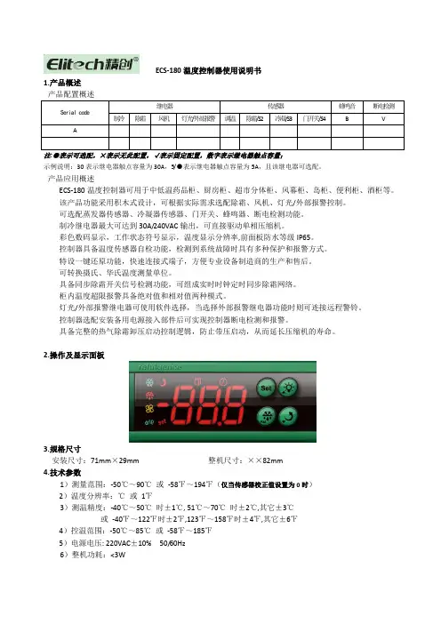
ECS-180温度控制器使用说明书1.产品概述Serial code继电器传感器蜂鸣音断电检测制冷除霜风机灯光/外部报警调温除霜/S2冷凝/S3门开关/S4B VA注:●表示可选配,×表示无此配置,√表示固定配置,数字表示继电器触点容量;示例说明:30表示继电器触点容量为30A,5/●表示继电器触点容量为5A,且该继电器可选配。
产品应用概述ECS-180温度控制器可用于中低温药品柜、厨房柜、超市分体柜、风幕柜、岛柜、便利柜、酒柜等。
该产品功能采用积木式设计,可根据实际需求选配除霜、风机、灯光/外部报警控制。
可选配蒸发器传感器、冷凝器传感器、门开关、蜂鸣器、断电检测功能。
制冷继电器最大可达到30A/240VAC输出,可直接驱动单相压缩机。
彩色数码显示,工作状态符号显示,温度显示分辨率,前面板防水等级IP65。
控制器具备温度传感器自检功能,检测到系统故障时具有多种保护和报警方式。
特设一键还原功能,快速连接式端子,方便专业设备制造商的生产和售后。
可转换摄氏、华氏温度测量单位。
具备同步除霜开关信号检测功能,可组成实时时钟定时同步除霜网络。
柜内温度超限报警具备绝对值和相对值两种模式。
灯光/外部报警继电器可使用软件选择,当选择外部报警继电器功能时则可连接远程警铃。
控制器选配安装备用电源接入部件后可实现控制器断电检测和报警。
具备完整的热气除霜卸压启动控制逻辑,防止带压启动,从而延长压缩机的寿命。
2.操作及显示面板3.规格尺寸安装尺寸:71mm×29mm 整机尺寸:××82mm4.技术参数1)测量范围:-50℃~90℃或-58℉~194℉(仅当传感器校正值设置为0时)2)温度分辨率:℃或1℉3)测温精度:-40℃~50℃时±1℃, 51℃~70℃时±2℃,其它±3℃或-40℉~122℉时±2℉,123℉~158℉时±4℉,其它±6℉4)控温范围:-50℃~85℃或-58℉~185℉5)电源电压: 220VAC±10% 50/60Hz6)整机功耗:<3W7)外部备用电源电压:~8)输入端口:柜温传感器、蒸发器传感器、冷凝器传感器、门开关(门打开时,传感器输出常开信号) 910)前面板防护等级:IP6511)工作环境温度:0℃~55℃12)存储温度:-25℃~75℃13)相对湿度:20%~85%(无结露)5.6.注①:仅在柜温传感器正常时有效。
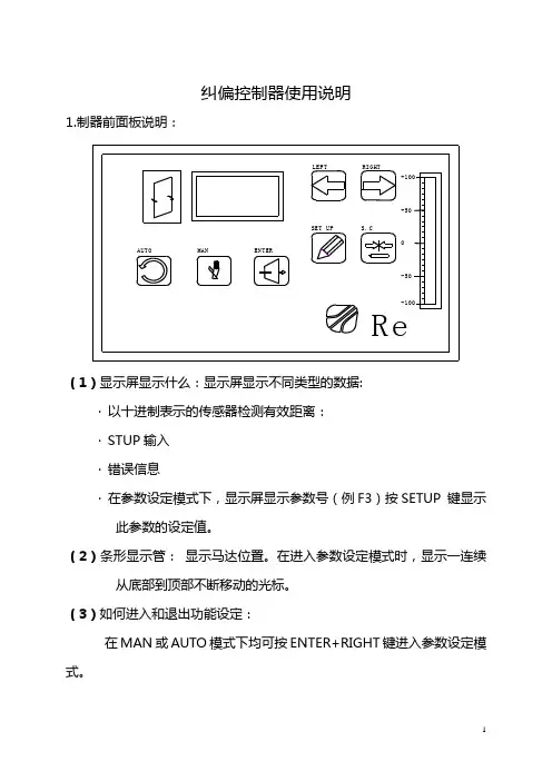
纠偏控制器使用说明1.(·以十进制表示的传感器检测有效距离:·STUP输入·错误信息·在参数设定模式下,显示屏显示参数号(例F3)按SETUP 键显示此参数的设定值。
(2)条形显示管:显示马达位置。
在进入参数设定模式时,显示一连续从底部到顶部不断移动的光标。
(3)如何进入和退出功能设定:在MAN或AUTO模式下均可按ENTER+RIGHT键进入参数设定模式。
按RIGHT或LEFT键可选择不同的参数。
退出参数设定模式同时按ENTER+LEFT键或选择参数F60.关于参数的设定模式下如何操作参阅参数设定。
(4)在MAN模式下如何进行纠偏(相应的MAN 指示灯亮)【1】在手动模式下纠偏…按MAN键进入手动控制模式(通常它是用来中断纠偏调整)。
MAN键的功能也可通过外部控制(详细信息参阅参数设定F42)【2】驱动中心…同时按SETUP+S.C键,驱动器定位在行程的中心位置(当限位开关位置改变时数码管显示的数值将超出±80,此时应按照参数F21进行设定。
【3】手动驱动器定位:…按LEFT和RIGHT键使驱动器定位在目标点上,同时按SETUP+LEFT或RIGHT键时可连续移动。
【4】驱动位置显示…按SETUP键显示驱动器相对参考点的位置,显示值单位是mm,0表示行程的中心位置。
(5)在AUTO模式下如何进行纠偏(相应的AUTO指示灯亮)【1】在AUTO模式下纠偏…按AUTO键进入自动纠偏控制模式。
…AUTO键的功能也可通过外部控制(详细信息参阅参数设定F42)【2】设置传感器有效范围值---SETUP----…按SETUP+LEFT或RIGHT键设定你需要的传感器合适的有效范围值(±80)。
通常0是设为保持材料在中心位置,如果你稍微修改材料位置,足够可以不移动传感器修改此数据。
2.参数列表:3.进入参数的方法:同时按下ENTER+RIGHT键即可进入参数设定模式。
拉矫机组操作说明书一.触摸屏画面切换本机组一共7个画面:主画面,收卷侧传动控制画面,开卷侧传动画面,辅助画面,电机风机控制画面,设置画面和报警信息画面;主画面主要包括机组的运行状态,系统速度和S辊张力的给定,以及实际反馈的运行速度,系统张力,开收卷卷径等信息,通过点击主画面报警信息按钮可以切换到报警信息画面,通过点击触摸屏幕下方的F1进入主画面;收卷侧传动控制画面包括收卷电机和左侧S辊组电机的合闸,分闸,运行状态以及实际的励磁电流,电枢电流,电机转速。
通过点击触摸屏幕下方的F2进入收卷侧传动控制画面;开卷侧传动控制画面包括开卷电机和右侧S辊组电机的合闸,分闸,运行状态以及实际的励磁电流,电枢电流,电机转速。
通过点击触摸屏幕下方的F3进入开卷侧传动控制画面;辅助画面包括液压泵A,液压泵B,循环泵的启动,停止,运行状态。
以及剪刀换刀的操作,通过点机辅助画面退出控制按钮可以退出WINCC FLEXIBLE的运行。
通过点击触摸屏幕下方的F4进入辅助画面;电机风机控制画面包括10个直流电机风机的启动,停止,运行状态;通过点击触摸屏幕下方的F5进入电机风机控制画面;设置画面主要是机组运行前一些必要的参数设置。
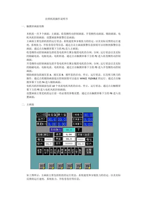
通过点击触摸屏幕下方的F6进入设置画面;二.主画面如上图所示,主画面主要包括机组的运行状态,系统速度和S辊张力的给定,以及实际反馈的运行速度,系统张力,开收卷卷径等信息;紧急停车文本显示绿色时为正常,显示红色时表示机组处于紧急停车状态;机组运行文本显示为绿色时表示机组处于运行状态,显示灰色表示机组尚未启动;传动文本显示为绿色时,表示6RA70全部就位并正常,显示为灰色时表示6RA70处于未合闸状态或故障状态;液压文本显示为绿色时表示液压系统运行正常,显示为灰色时表示液压系统未启动状态或报警状态;正向文本显示为绿色时表示机组运行方向向左(机组正常工作方向),显示为灰色表示机组运行方向向右;零速文本显示为绿色时表示机组处于零速状态;单动文本显示为绿色时表示机组处于单动状态;联动文本显示为绿色时表示机组处于联动状态;收紧文本显示为绿色时表示机组处于拉紧模式;工作文本显示为绿色时表示机组处于工作模式;换卷文本显示为绿色时表示机组处于换卷模式;报警信息文本显示为绿色时表示机组正常,显示为红灰来回闪烁时表示系统有报警,具体报警信息通过点击触摸屏上报警信息按钮切换到报警信息界面;此画面包括入口S辊组张力(单位为吨)的给定值和所允许给定的最大值以及系统速度(单位为米/秒)的给定值和所允许给定的最大值。
User ManualDEUTSCHBedienungsanleitung ESPAÑOLManual del Usuario FRANÇAIS Mode d’Emploi IT ALIANOManuale UtenteENGLISH User Manual Acorn 180Curved StairliftT565275175993Acorn Stairlifts User Manual3Thank you for choosing Acorn.You can rest assured that your stairlift will provide many years of reliable serviceand allow you to enjoy the full use of your home.Your stairlift is covered by a manufacturer’s warranty for 12 monthsthat covers the cost of replacement parts.Ensure that only an authorized and qualified Acorn trained engineer installs and services thestairlift. Under no circumstance should anyone other than an engineer trained and authorized to install, adjust, service or modify any mechanical or electrical device on this product. Failure to follow this warning may result in safety system compromises which could result in serious injury or death. Acorn accepts no liability for property damage, warranty claims or personalinjury, including death, in this circumstance.After installation, reliable operation and continual safe operation requires regular service and inspection. As the owner, you are responsible for ensuring that regular service andinspections occur in a timely manner.The Stair lift owner is required to inspect the following functions every 2 months:General operation of the Stair lift.The operation of the safety sensors.Rail and carriage are free of debris.Once a year, it is mandatory to call your Acorn/authorized dealer to perform the annual inspection, that includes all maintenance and safety inspections and repairswhere necessary.Regular maintenance is essential for keeping your stairlift in proper operating condition. We strongly recommend that you only use authorized engineers to perform allrequired maintenance, service and repair work.Acorn, in keeping with its policy of continual development, reserves the right to change specification without prior notice. All measurements are approximate. All images areshown for illustrative purposes only. Product may vary slightly.Acorn Stairlifts User ManualE N G L I S H4IMPORT ANT!Always wear the seatbelt, ensure it is fastened securely at all times during operation.DANGER!Do not allow children to play with the e by children should always be supervised.WARNING!Ensure other members of your household or visitors are aware that the stairlift is installed. Make them aware of any potential trip hazards(rail, hinge, footplate).DANGER!The stairlift is designed to carry one person at a time. Never attempt to carry more thanone person.Do NOT exceed published weight capacity. Operating any lifting device exceeding weight capacity could resultin serious injury.DANGER!Ensure that household pets are out of harm’s way beforeusing the stairlift.Acorn Stairlifts User Manual 4WARNING!Do not transport food, animals, laundry or any other items. Do not use the stairlift for anything other than its intended use.WARNING!Ensure that the stairway is not being used by others and is clear of articles or obstructions before using the stairlift.WARNING!T o avoid injury do not make contact with moving parts.IMPORT ANT!Please ensure that you canalert others in case you encounter difficulties whenusing the stairliftIMPORT ANT!T o guard against injury, important safety precautions should be observed.IMPORT ANT!Relax and sit well back in the seat with your arms on the armrests and your feet well back on the footrest.Acorn Stairlifts User Manual E N G L I S H5Acorn Stairlifts User Manual5WARNING!If a standard top finish rail isinstalled, the seat will be required to swivel to enter and exit the stairlift. Always ensure the seat is rotated and locked in position at a 450 or 880 angle when entering andexiting the stairlift.WARNING!Do not disconnect the power supply. This will make the stairlift batteries lose their charge, and thestairlift will not operate.WARNING!The stairlift must not be used for firefighting or for evacuationduring a fire.WARNING!Ensure that the swivel seat is in the locked positionbefore and during travel and beforegetting on or off the stairlift.DANGER!Ensure that there are no articles of your clothing (scarves, dressing gowns, cardigans) that could become trapped in the stairlift mechanism, as this could result in personal injury and/or damage to the equipment. Always check that your clothing is clear of the stairliftand rail before operation.CAUTION!It is possible for small items to be dropped onto the stairlift rail and then slide down the rail and into the stairlift mechanism. If you suspect that any foreign object has become trapped in the equipment, consult your Acorn representative beforefurther use.DANGER!Always consult your Acorn representative if the need for an authorized engineershould arise.WARNING!Do not operate the stairlift if under the influence of alcohol or drugs. If unsure, ask yourphysician for advice.WARNING!Do not use the stairlift if you have not been given a demonstration by the installation engineer.PLEASE KEEP THESE SAFETY NOTES TO HANDFOR EASE OF REFERENCEAcorn Stairlifts User Manual67The Acorn 180 Curved Stairlift is an electrically powered stairlift designed for domestic use. If used correctly, it will provide many years of safe, reliable service. It is designed to carry one person weighing no more than120kg (264lbs/18.8 stone).It is important for your safety that you study this manual tocompletely familiarise yourself with your stairlift.The pictures in this manual show a stairlift on the left hand side of the stairs. Stairlifts on the opposite side of the stairs operatein exactly the same way.Seat Armrest Status indicator Safety Edges Footrest Charging points Rail CarriageSeat swivel release paddleSeatbeltDirection controllerAcorn Stairlifts User ManualE N G L I S H11The stairlift batteries are recharged from charging points when the stairlift is in its parked position at the top and the bottom of the stairs or parking on an intermediate point if a hinge is fitted. The charging points are connected to the mains electricity supply through a DC power supply.E N G L I S HPress the up button to send the stairlift to its autopark position.When the stairlift is switched on, the diagnostic display underneath the seat is illuminated. During normal operation it will display these symbols:E N G L I S HWipe the seat, carriage and rail down with a dry cloth.Replace the remote control batteries annually.See Page 15.Acorn promotes responsible recycling. Do not attempt to dispose of the stairlift yourselfIt is recommended that your Acorn 180 Stairlift be serviced every 12 months by your stairlift supplier to ensure it remains safe and reliable.The equivalent continuous A-Weighted sound pressure level ofthis equipment does not exceed 70db (A).For safety reasons, only Acorn specified parts should be used. Useof parts that are not Acorn approved could affect the safetyof your stairlift.If the stairlift is not parked on a charge point, or in the event of a power failure, the stairlift will ‘beep’ continuously for approximately 60 seconds, after which the stairlift will enter SLEEP MODE. The Stairlift will beep intermittently every 20 seconds and the fault indicator will go blank. The user can ‘wake’ the stairlift at any time by using the paddle controls or remote control handset. Oncewoken, park the stairlift on a charge point as normal.FCCThe equipment has been tested and complies fully with Class A of 47CFR 2011 part 15 certification. If not installed correctly by an Acorn Qualified T echnician there may be some interference with other household equipment (i.e TV and Radio reception). This can be rectified by moving thisequipment to a different location.E N G L I S HAcorn Stairlifts User Manual22Acorn Stairlifts User Manual E N G L I S H23FUSE 25AReplace with same type and value24Acorn promotes responsible recycling. Do not attempt to dispose of the stairlift yourselfAcorn Mobility Services Ltd.Telecom House Millennium Business Park Station Road, Steeton West Yorkshire, England BD20 6RBT: +44 (0) 1535 290 000F: +44 (0) 1535 290 Lothian Electric Machines Ltd.Hospital Road Haddington East Lothian Scotland EH41 3PD T: +44 (0) 1620 828 700F: +44 (0) 1620 828 Manufacturer:Product: Stairlift Serial No: Model: Acorn 180 Curved StairliftDate: May 2018The Technical Construction File, as required by Directive 2006/42/EC is maintained at the corporate headquarters of Acorn Mobility Services Ltd, Telecom House,Millennium Business Park, Station Road, Steeton, England. BD20 6RB.COPYRIGHT ©2017 ACORN MOBILITY SERVICES LIMITED All Rights Reserved42112-212 / AC10002 / 0518Acorn reserves the right to change specification without prior notice. All measurements are approximate. Images are shown for illustrative purposes only. Product may vary slightly.All information correct at time of going to print. E&OE.。


180/440型AUTOTROL控制阀操作使用手册广州市大自然水处理技术开发有限公司 2004年版一.180/440控制器图释:(一)控制器设定说明:1.再生或冲洗时间设定:将控制面板的右下方(TimerKnob)时间盘拔起,任意角度旋转。
将(Time Arrow)时间指针指向当时的北京时间。
根据AUTOTROL公司出厂默认参数,当时间指针指向当时的时间,程序就会在凌晨2:00自动进入再生或冲洗程序。
2.再生或冲洗日期设定:将控制面板的上部(SkipperWheel)天数盘上的(Skipper Pins)天数销,推进为再生或冲洗、拔出为不再生或冲洗。
3.再生或冲洗程序手动影发:将(Indicator Knob)程序按钮按下并逆时针旋转至(Start)开始位臵即可。
程序会自动运行。
二.180本体设臵:4.180阀体程序销钉设置三.软水器、过滤器的安装:(一)顶装形式:1.安装要求:1)软水器要应安放在牢固的水泥平台上,附近应设有排水道,且排水管的排水量应和软水器的排水量相配。
2)储盐箱(盐筒)应安放在靠近树脂罐的地方,两者间距不大于200MM,并尽量缩短吸盐管的长度。
3)软水器与加热设备直接相连时,应保持3米以上的管距并安装单向阀。
4)储盐罐的放臵应便于再生剂的补充。
5)设备附近应当留有操作及检查修的空间。
(二)侧装形式:2.管道连接:1)管道的连接请参照当地施工规范的有关内容。
2)按照控制阀口径连接进口出水管。
3)进出水管应装有手动阀门,进出水管之间应装有旁通阀,出水管应安装取样阀,进水管道建议安装Y型过滤器。
4)尽量缩短排水管的长度,减少弯度,控制阀与排水道距离不超过2米。
5)排水管与排水道连接时,必须使排水管与排水道的水面保持一定的空间,防止活水被子虹吸返回软水器。
6)排水管道中不得安装各类阀门。
7)盐水管的连接一定要保持良好的密封性,否则会影响软水器的再生效果。
8)在盐水罐的预留孔位上安装溢流口,并配接头塑料管(用户自购),引至排水道.。
纠偏控制器
1.设置行程:点击手动——设置——电机行程——手动往左走——走到底退回一点——点
击保存——手动右走——到底退回一点——保存。
2.设置传感器:选取所用传感器(现只用右边一个)——进入设置——传感器——用手遮
挡大14%左右——选取保存——再次用手遮挡85%左右——选取保存。
(在14%和85%位置各有红线标示,在标示位置即可)
3.在设置界面可选取电机方向正反。
4.拨动拨码开关1(1为紫外线传感器),2或3为自动时走动方向(如方向不正确可拨动)
拨动后如无变化尝试断电重启。
5.以上为紫外线传感器设置。
CCD跟线模式不用设置传感器步骤,设置行程即可。
6.电机速度和增益按生产实际情况增减。
注意:速度越大电机可能会有抖动现象,要适当
减小。
如产生电机保护增益可以适当调大,
7.设置完成后,在各种状态调试下,看电机有无自动保护,正常状态不会自动保护。
电机有无异常。
8.注意纠偏器内接线,有屏蔽线漏出现象,会产生烧坏控制器或通信异常及控制不稳定现
象。
现有一台有电机自动保护现象。
一台电机有异常,抖动很厉害。

纠偏控制系统使用说明书上海科先集团纠偏事业部20120122年01月9日安全规范:根据纠偏控制系统在实际中的经验和要求,KXMCU板带纠偏控制系统的电气、机械、液压是安全可靠的。
为了避免损坏或破坏设备元件,特作以下规范。
1系统的所有设备只能由有资质人员进行安装、连接、调试、维护和操作,安装调试前必须认真阅读说明书。
2调试人员必须有相关的电气资质及工作经验。
3设备必须有专门的人员负责维护保养,其他无关人员禁止乱动。
4为了保证设备的正常效果,所有信号连接线应采用屏蔽电线连接,屏蔽连接电线尽量和动力电缆隔离布置。
1系统介绍1.1概述KXMCU型带材高速高精度自动纠偏控制系统适合用于各种不透光带材的自动纠偏,可使高速运行的带材始终处于中间要求的区域内,彻底的解决的带材的跑偏|、刮边、断带现象。
带材纠偏电液伺服控制系统是集机、电、液、光四方面有机结合,进行全闭环控制的电液伺服系统,是用途广泛的机电一体化高新技术产品。
KXMCU板带纠偏控制系统包括以下元件:高精度光电传感器、线性位移传感器、GS红外线发光源、比例伺服阀、伺服阀放大器、纠偏控制器(KXMCU)以及其他部件组成,在实际应用中,任何一个部件的损坏都会导致纠偏系统的不能正常使用。
传感器一般根据EPC和CPC的应用大概可以分为二类,EPC一般选用GPRS8-2对射式对边光电传感器附带找边架,CPC一般选用GDHZ型光电对中传感器和DMM自动找边两种,二种传感器都灵活的根据带材的不同宽度可以自动纠偏,为用户提供了极大的方便。
EPC一般选用GPS8-2对射式光电传感器,传感器安装在可以随着丝杠直线找边的找边架上,找边架根据客户的需要分为DM自动找边架和手动找边架,手动找边架适合客户长期的加工生产同种规格的带材,而自动找边架则根据客户的不同带材宽度灵活的寻找带材边沿,使用方便。
一般情况下找边架安装于收卷液压剪刀和收卷转向辊之间,传感器的安装位置和带材的平面垂直距离一般保持在35cm左右,找边架的水平距离取决于客户的带材的宽度变化范围,GS管发光源和找边架的垂直距离保持在一米之间,安装GS管发光源时候要注意,找边架安装完成后,安装固定好GPS8-2传感器后,以GRS8-2的中心为基准点,GS红外发光源的一排发射小灯应和GPS8-2的中心垂直。

纠偏控制器使用说明:
1、伺服闭环控制,运行平稳,实现了极限位置设定、中心位置设定。
比采用直流伺服电机、步进电机减少了外加编码器或限位传感器和回中传感器。
2、自动刹车功能提高纠偏精度。
在高速纠偏运行肓区停止时,停止后因惯性会移动造成纠偏停止不了,控制器通过刹车解决。
3、不同物体纠偏只要校准传感器轻松解决。
适用透明材料、半透明材料、感光材料、不透明材料。
4、多种组合减少你的投资。
ARS纠偏系统有三个系列,十九个产品可根据客户需求进行组合。
5、IPM智能驱动模块轻松解决重负载启动,确保纠偏精度。
ARS系列采用IPM智能驱动模块,电机启动力矩2倍于额定力矩,有效解决重负载启动。
自动识别系统JHS-180 中文操作说明书目录1 1.1 1.22 2.1 2.1.1 2.1.2 2.2 2.2.1 2.3 2.3.1 2.3.23 3.1 3.1.1 3.1.2 3.1.3 3.1.4 3.1.5 3.2 3.2.1 3.2.2 3.2.3 3.2.4 3.3 3.3.1 3.3.2 3.3.3 3.3.4 部件名称和功能--------------------------------------------------------------------操作面板-----------------------------------------------------------------------------显示-----------------------------------------------------------------------------------基本操作-------------------------------------------------------------------------------开电源----------------------------------------------------------------------------------他船清单-------------------------------------------------------------------------------他船详细清单-------------------------------------------------------------------------关电源----------------------------------------------------------------------------------关显示----------------------------------------------------------------------------------报警-------------------------------------------------------------------------------------警戒区报警----------------------------------------------------------------------------消失目标警报-------------------------------------------------------------------------主菜单----------------------------------------------------------------------------------信息菜单-------------------------------------------------------------------------------编辑与发射----------------------------------------------------------------------------发射屏----------------------------------------------------------------------------------接收屏----------------------------------------------------------------------------------查询-------------------------------------------------------------------------------------长度范围信息-------------------------------------------------------------------------目的地设置----------------------------------------------------------------------------目的地----------------------------------------------------------------------------------航点-------------------------------------------------------------------------------------估计到达时间-------------------------------------------------------------------------航点-------------------------------------------------------------------------------------航行信息设置-------------------------------------------------------------------------航行状况信息-------------------------------------------------------------------------在船人员-------------------------------------------------------------------------------船舶和货物类型----------------------------------------------------------------------吃水深度-------------------------------------------------------------------------------11222233444455589911121213141415161616173.3.5 3.4 3.4.1 3.4.2 3.5 3.5.1 3.5.2 3.6 3.6.1 3.6.2 3.6.3 3.6.4 3.6.5 3.6.6 3.7 3.7.1 3.7.2 3.7.3 3.7.4 3.7.5 3.7.6 龙骨以上高度------------------------------------------------------------------------报警设置-------------------------------------------------------------------------------距离-------------------------------------------------------------------------------------消失物标------------------------------------------------------------------------------船队设置-------------------------------------------------------------------------------船名------------------------------------------------------------------------------------- MMSI(船舶移动识别码)-----------------------------------------------------------设置菜单-------------------------------------------------------------------------------密码设置-------------------------------------------------------------------------------信道处理设置-------------------------------------------------------------------------本船数据显示设置-------------------------------------------------------------------长距离应答设置----------------------------------------------------------------------对比度设置----------------------------------------------------------------------------重发号码设置-------------------------------------------------------------------------维护菜单-------------------------------------------------------------------------------收发状况对数显示-------------------------------------------------------------------自动识别系统报警显示-------------------------------------------------------------传感器状况显示----------------------------------------------------------------------电源开/关对数显示-------------------------------------------------------------------发射关对数显示----------------------------------------------------------------------软件版本显示-------------------------------------------------------------------------1718181818191920202123242425252526262728281.部件名称与功能1.1 操作面板(1)LCD面板更多信息参考“1.2显示”。
易典纠偏器说明书光电纠偏控制器.使用说明书接线及输入输出端口说明1、为对边对线光电头输出插口,即可作对边检测口作用,又可作对线检测口作用,三芯航空插接口。
可配一般光电头如Z3N一TB22使用。
2、为对线光电头输入插口,可作对线检测口作用,三芯航空插接口。
可配一般光电检测器使用。
3、为四芯光电检测器(如ZPS一2系列槽形双路光电头)输出插口,既可作对边检测口作用,又可作对线检测口作用。
7和8为左限位开关输入端口,接左限位开关常开触头。
9和10为右限位开关输出端口,接右限位开关常开触头。
交流同步电机的红色、黄色、白色和蓝色四线对应接入6、5、4、 3四个接线端子。
(调换红色与蓝色接线可改变电机旋转方向。
)220V电源接入1、2两接线端子。
二、运行前的准备工作1、接线:按接线图要求将电源,电机,限位开关,光电头对应接好。
2、电机方向极性确定:(如按手动键,使控制器处于手动状态,再按极性正键),则按键,电机正方向旋转,材料活动架往左移动,按键,电机反方向旋转,材料活动架往右移动,如电机旋转方向与实际相反,可将电机红蓝两线调换接.线.3、限位开关控制电机停止方向确定:(如按手动键,使控制器处于手动状态,再按极性正键),则按键,电机正方向旋转,后碰触活动架移动方向的限位开关,电机运转停止,则表示限位有效,反之则碰触一端限位开关,电机应运转停止,则表示限位开关接线相反,必须给予调换.注意:检验限位开关时必须在电机运转的有效行程内,必须在手动档检验,否则一但限位失灵将损坏电机丝杆的机械结构。
4、材料对边或对线选择:对于材料首先确定它的基准位置是材料边缘还是印刷线条。
确定跟踪边缘以后,再确定左边缘还是右边缘,以后再决定电机方向极性。
对于印刷品的线条一般定于2MM以上线条作为对边处理。
反之则作为对线处理。
5、光电头的定位、调整:按自动键、对边对线键,确定是跟踪材料边缘或印刷线条后,将光斑对准材料边缘或印刷线条,调整光电头位置观察光电头上的指示灯,指示灯从亮一暗一亮,则表示设定成功,若无该状态,则无基准工作。
纠偏控制器使用说明
一、简介
纠偏控制器是一种专门用于控制和纠偏的仪表和装置,它是集成多种系统的综合装置,能够快速准确地对船舶或航空器进行位置和航向纠偏。
使用纠偏控制器可以有效减少船舶或航空器的位置偏差,避免海上或空中碰撞发生,提高船舶或航空器的安全性。
二、功能
1.实时位置控制:它可以实时检测并校正船舶或机载设备的位置,从而提高船舶安全性和准确度。
2.高精度测距:它可以快速准确地测量船舶和其他物体之间的距离,从而实现良好的船舶航行安全。
3.高精度航向控制:它可以快速准确地控制船舶的航向,以避免碰撞或失去航行方向。
4.电路保护:纠偏控制器可以自动保护船舶和电路,避免由于海洋环境引起的过度电压或电流所带来的损坏影响。
三、结构
纠偏控制器由控制器、测距仪、航向控制器、护器、液压系统和接收机组成。
控制器是纠偏控制器的核心部件,它负责测距仪、航向控制器、护器、液压系统和接收机的控制,并实现实时的位置纠偏和航向纠偏。
测距仪主要用来测量船舶与其他物体的距离,以避免碰撞发生。
航向控制器用来控制船舶的航向,使船舶能够顺利地航行。
•ON/OFF MENUSWITCH•BATTERY DOOR•1/4 X 20 INSERTIN BASE OF EACH UNIT•USE EITHER3 AA1.5VALKALINE ORNICADBATTERIES•OPTIC WINDOWS•MAGNETICWALL BRACKET• POUCH• PLS SLD LASERDETECTORPLS180 and PALM LASER are registeredtrademarks of PLS •PACIFIC LASER SYSTEMSPLS180 Patent PendingO PERA TINGM ANUALFEA TURES MENU SWITCH SAFETY LABELINGPRESS “ON” TO SCROLL THROUGH THE MENU.THE NUMBERS INDICATE MENU FUNCTIONS:1. LEVEL/HORIZONTAL BEAM / GREEN LED2. PLUMB/VERTICAL BEAM / GREEN LED3. BOTH BEAMS - SELF-LEVELING/ GREEN LED4. BOTH BEAMS - FIXED/RED LED5. OFF•UNLESS THE PLS180 IS ON NUMBER 4 MODE, UNITWILL NOT OPERATE IF TILT EXCEEDS 6OUT OF LEVEL.•AMBER LED = LOW BATTERY•PLS180 MENU SAME AS ABOVE. PRESS “PULSE ON”BUTTON TO ACTIVATE PULSED BEAM TO USE OUT-DOORS WITH PLS SLD LASER DETECTOR.•FLASHING LED INDICATES LASER IS PULSING ANDCAN BE USED WITH PLS SLD LASER DETECTOR.•PULSED BEAM WILL BE LESS BRIGHT THAN NON-PULSED BEAM.CAUTION: USE OF CONTROLS, ADJUST-MENTS OR PROCEDURES OTHER THANTHOSE SPECIFIED HEREIN MAY RESULTIN HAZARDOUS RADIATION EXPOSURE.PLS180 complies with US FDAstandards, 21 CFR, Subchapter J.Except for external cleaning there isnothing the owner needs to do to maintainthis product.These labels are attached to every PLS laser.These are not to be removed or defaced.PLS • 2550 KERNER BLVD., SAN RAFAEL, CA949018006014500AVOID EXPOSURELASER RADIATIONEMITTED FROMTHIS APERTURE PLS180 Palm LaserPLS180COMPLIES WITH FDA PERFORMANCE STDS.21 CFR, SUBCHAPTER JSERIAL NUMBER:MFG’D:CAUTION: LASER RADIATION WHEN OPEN. DO NOTSTARE INTO BEAM OR VIEW DIRECTLY WITH OPTICALINSTRUMENTS. PATENT PENDINGREG. US PATENT OFFICEPLS 2550 KERNER BLVD., CA 94901C A U T I O NLASER RADIATIONDO NOT STARE INTO BEAM OR VIEWDIRECTLY WITH OPTICAL INSTRUMENTSMAX OUTPUT POWER <1mWWAVELENGTH 635-670nmCLASS II LASER PRODUCTWARNING LABELBACKFRONTAPERTURELABELID# CERTIFICATION LABEL®P A C I F I C L A S E RS Y S T E M SThe Professional StandardCHECK PLUMBCHECK LEVELW ARRANTYSPECIFICA TIONSLight source:Semiconductor laser diode 635-670 nm, visibleWorking range:+/- 100 feet (outdoor w/detector)Accuracy:<1/8” @ 30 feet (outdoor w/detector)(<3mm @ 10 meters)Leveling:Automatic Leveling range +/- 6oPower supply: 3AA batteriesalkaline or rechargeableOperating time:+25 hours continuous use with single beam; 12.5 hours both beamsOperating temp: 0o F to 122o F (-18o C to 50o C)Storage temp:-40 F to 158o F (-40o C to 70o C)Indicator:Green light: ONRed light: EXCEEDS TILT/TILT OVERRIDE #4Amber light:BATTERY LOW Flashing: pulse beam-PLS180 Environment:Water resistant; not submersible Dimensions:2” x 2-7/8” x 3-3/8”Weight:10 oz.(.28kg) (including batteries)We recommend that you check your PLS180periodically in order to assure its accuracy.TO CHECK LEVEL:Choose two interior walls approximately 15’-0”apart (see Fig. 1). You can use 2 x 4s for targets.Turn on the PLS180 to setting #1 (level). With the PLS180 six inches away from and facing target #1, carefully mark the center of the line. Label this mark A1. Swivel the laser 180º and mark the center of the line on target #2. Label this mark B1.Move the PLS180 six inches away from and facing target #2. Carefully mark the center of the line. Label this mark B2. Swivel the laser 180º and mark the center of the line on target #1. Label this mark A2.You now have two centers of elevation at each target. Carefully measure the distance between centers of each set of marks. If there is a differ-ence, subtract one measurement from the other.This calibration method magnifies any error by a factor of two. Therefore divide any difference by two to find the true error. Your PLS180 should have an error of no greater than 1/8in. within 30ft.Choose a door jamb with 8’-0” clear on each side of the door. Turn on your PLS180 laser to setting #2 (plumb). With your laser at point A, make two marks on the floor: the first at 8’-0” from point A centered on door header above (mark this point B), the second 16’-0” from point A (mark this point C). Without moving the laser, make a third mark on the door header (mark this point D).Move the laser to point C, exactly align the beam with point B, and notice where the beam falls at point D. If it is within a “light” 1/16” of point D, the laser is in calibration.This product is warranted by PLS ·Pacific Laser Systems to the original purchaser to be free from defects in material and workmanship under normal use for a period of one year from the date of purchase. During the warranty period, and upon proof of purchase, the product will be repaired or replaced (with the same or similar model at our option), without charge for either parts or labor, through PLS. The purchaser shall bear all shipping, packing and insurance costs.Upon completion of the repair or replacement, the unit will be returned to the customer, freight prepaid. The warranty will not apply to this product if it has been misused, abused or altered. Without limiting the foregoing, battery leakage, dents or gouges to the plastic housing, broken optic win-dows, damage to the switch/LED membrane are presumed to result from misuse or abuse.Tampering with or removal of the caution or certification labels voids this warranty.Neither this warranty nor any other warranty,express or implied, including implied warranties of merchantability, shall extend beyond the warranty period. No responsibility is assumed for anyincidental or consequential damages. This warranty gives you specific legal rights, and you may have other rights which vary from state to state.ADC••B••Target #1Target #2PLS180PLS180PLS Lab TechniciansA1+ A2B1+ B2-15’If level & plumb are within specification, square will be in specification.FAN ANGLE 180+。