污水处理工业废水回用中英文对照外文翻译文献
- 格式:doc
- 大小:51.50 KB
- 文档页数:13
污水处理工业废水回用中英文对照外文翻译文献XXX and resource recovery in us industries。
and they are of significant XXX-catalysis has been well established for water recovery and reuse。
chemo-catalysis is only starting to make an XXX-catalytic processes for water reuse。
XXX。
XXX.2.Chemo-XXX reuseChemo-XXX。
including XXX。
One of the most promising ns of chemo-XXX。
XXX。
This process has been shown to be effective in removing COD (chemical oxygen demand) XXX.3.XXX COD removalXXX treatment。
The process involves the use of a XXX can be a metal oxide or a metal complex。
and the oxidizing agent can be hydrogen peroxide。
ozone。
or XXX mild ns。
and the process is XXX.4.XXXXXX (AOPs) such as XXX。
photo-Fenton n。
and electro-XXX include the use of anic frameworks (MOFs) XXX.5.nIn n。
chemo-catalytic processes。
XXX。
XXX。
such as AOPs。
MOFs。
and nanomaterials。
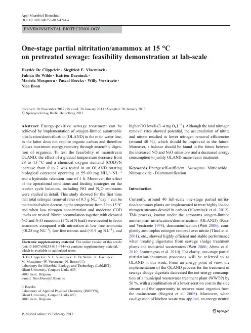
ENVIRONMENTAL BIOTECHNOLOGYOne-stage partial nitritation/anammox at15°Con pretreated sewage:feasibility demonstration at lab-scale Haydée De Clippeleir&Siegfried E.Vlaeminck&Fabian De Wilde&Katrien Daeninck&Mariela Mosquera&Pascal Boeckx&Willy Verstraete&Nico BoonReceived:26November2012/Revised:28January2013/Accepted:30January2013#Springer-Verlag Berlin Heidelberg2013Abstract Energy-positive sewage treatment can beachieved by implementation of oxygen-limited autotrophicnitrification/denitrification(OLAND)in the main water line,as the latter does not require organic carbon and thereforeallows maximum energy recovery through anaerobic diges-tion of organics.To test the feasibility of mainstreamOLAND,the effect of a gradual temperature decrease from29to15°C and a chemical oxygen demand(COD)/Nincrease from0to2was tested in an OLAND rotatingbiological contactor operating at55–60mg NH4+–NL−1 and a hydraulic retention time of1h.Moreover,the effectof the operational conditions and feeding strategies on thereactor cycle balances,including NO and N2O emissionswere studied in detail.This study showed for the first timethat total nitrogen removal rates of0.5g NL−1day−1can bemaintained when decreasing the temperature from29to15°Cand when low nitrogen concentration and moderate CODlevels are treated.Nitrite accumulation together with elevatedNO and N2O emissions(5%of N load)were needed to favoranammox compared with nitratation at low free ammonia(<0.25mg NL−1),low free nitrous acid(<0.9μg NL−1),and higher DO levels(3–4mg O2L−1).Although the total nitrogen removal rates showed potential,the accumulation of nitrite and nitrate resulted in lower nitrogen removal efficiencies (around40%),which should be improved in the future. Moreover,a balance should be found in the future between the increased NO and N2O emissions and a decreased energy consumption to justify OLAND mainstream treatment. Keywords Energyself-sufficient.Nitrospira.Nitricoxide. Nitrous oxide.DeammonificationIntroductionCurrently,around40full-scale one-stage partial nitrita-tion/anammox plants are implemented to treat highly loaded nitrogen streams devoid in carbon(Vlaeminck et al.2012). This process,known under the acronyms oxygen-limited autotrophic nitrification/denitrification(OLAND)(Kuai and Verstraete1998),deammonification(Wett2006),com-pletely autotrophic nitrogen removal over nitrite(Third et al. 2001),etc.,showed highly efficient and stable performance when treating digestates from sewage sludge treatment plants and industrial wastewaters(Wett2006;Abma et al. 2010;Jeanningros et al.2010).For clarity,one-stage partial nitritiation/anammox processes will be referred to as OLAND in this work.From an energy point of view,the implementation of the OLAND process for the treatment of sewage sludge digestate decreased the net energy consump-tion of a municipal wastewater treatment plant(WWTP)by 50%,with a combination of a lower aeration cost in the side stream and the opportunity to recover more organics from the mainstream(Siegrist et al.2008).Moreover,when co-digestion of kitchen waste was applied,an energyneutral Electronic supplementary material The online version of this article(doi:10.1007/s00253-013-4744-x)contains supplementary material,which is available to authorized users.H.De Clippeleir:S.E.Vlaeminck:F.De Wilde:K.Daeninck:M.Mosquera:W.Verstraete:N.Boon(*)Laboratory for Microbial Ecology and Technology(LabMET),Ghent University,Coupure Links653,9000Gent,Belgiume-mail:Nico.Boon@UGent.beP.BoeckxLaboratory of Applied Physical Chemistry(ISOFYS),Ghent University,Coupure Links653,9000Gent,BelgiumAppl Microbiol BiotechnolDOI10.1007/s00253-013-4744-xWWTP was achieved(Wett et al.2007).To fully recover the potential energy present in wastewater,a first idea of a new sustainable wastewater treatment concept was reported (Jetten et al.1997).Recently,a“ZeroWasteWater”concept was proposed which replaces the conventional activated sludge system by a highly loaded activated sludge step (A-step),bringing as much as organic carbon(chemical oxygen demand(COD))as possible to the solid fraction, and a second biological step(B-step)removing the residual nitrogen and COD with a minimal energy demand (Verstraete and Vlaeminck2011).Subsequently,energy is recovered via anaerobic digestion of the primary and sec-ondary sludge.For the B-step in the main line,OLAND would potentially be the best choice as this process can work at a low COD/N ratio,allowing maximum recovery of COD in the A-step.Moreover,it was calculated that if OLAND is implemented in the main water treatment line and a maximum COD recovery takes place in the A-step,a net energy gain of the WWTP of10Wh inhabitant equivalent (IE)−1day−1is feasible(De Clippeleir et al.2013).To allow this energy-positive sewage treatment,OLAND has to face some challenges compared with the treatment of highly loaded nitrogen streams(>250mg NL−1).A first difference is the lower nitrogen concentration to be removed by OLAND.Domestic wastewater after advanced concen-tration will still contain around30–100mg NL−1and113–300mg CODL−1(Metcalf and Eddy2003;Tchobanoglous et al.2003;Henze et al.2008).High nitrogen conversion rates(around400mg NL−1day−1)by the OLAND process can be obtained at nitrogen concentrations of30–60mg N L−1and at low hydraulic retention times(HRT)of1–2h(De Clippeleir et al.2011).A second challenge is the low tem-perature at which OLAND should be operated(10–15°C compared with34°C).Several studies already described the effect of temperature on the activity of the separate micro-bial groups(Dosta et al.2008;Guo et al.2010;Hendrickx et al.2012).Only a few studies showed the long-term effect of a temperature decrease below20°C on the microbial bal-ances of anoxic and aerobic ammonium-oxidizing bacteria (AnAOB and AerAOB)and nitrite-oxidizing bacteria (NOB)at nitrogen concentrations above100mg NL−1 (Vazquez-Padin et al.2011;Winkler et al.2011).However, the combination of low temperature and low nitrogen con-centration was never tested on a co-culture of AerAOB, AnAOB,and NOB before.At temperatures around15°C, maintaining the balance between NOB and AnAOB and the balance between NOB and AerAOB will get more challeng-ing since the growth rate of NOB will become higher than the growth rate of AerAOB(Hellinga et al.1998). Therefore,it will not be possible to wash out NOB based on overall or even selective sludge retention.The third and main challenge in this application will therefore be the suppression of NOB at temperature ranges of10–20°C and at nitrogen concentration ranges of30–60mg NL−1 (low free ammonia and low nitrous acid),which was not shown before.A final fourth challenge will include the higher input of organics at moderate levels of90–240mg biodegradable CODL−1in the wastewater.Depending on the raw sewage strength,COD/N ratios between2and3are expected after the concentration step,which is on the edge of the described limit for successful OLAND(Lackner et al. 2008).The presence of organics could result in an extra competition of heterotrophic denitrifiers with AerAOB for oxygen or with AnAOB for nitrite or organics,since certain AnAOB can denitrify consuming organic acids (Kartal et al.2007).In this study,the challenges2to4,were evaluated in an OLAND rotating biological contactor(RBC).This reactor at 29°C was gradually adapted over24,22,and17to15°C under synthetic wastewater conditions(60mg N L−1, COD/N of0).Additionally,the COD/N ratio of the influent was increased to2by supplementing NH4+to diluted sewage to simulate pretreated sewage.The effect of the operational conditions and feeding strategies on the reactor cycle balan-ces,including gas emissions and microbial activities were studied in detail.An alternative strategy to inhibit NOB activity and as a consequence increase AnAOB activity at low temperatures based on NO production was proposed. Materials and methodsOLAND RBCThe lab-scale RBC described by De Clippeleir et al.(2011) was further optimized at29°C by an increase in the influent nitrogen concentration from30to60mg NL−1and a limitation of the oxygen input through the atmosphere by covering the reactor before this test was started.The reactor was based on an air washer LW14(Venta,Weingarten, Germany)with a rotor consisting of40discs interspaced at 3mm,resulting in a disc contact surface of1.32m2.The reactor had a liquid volume of2.5L,immersing the discs for 55%.The latter was varied over the time of the experiment. The reactor was placed in a temperature-controlled room. The DO concentration was not directly controlled.In this work,continuous rotation was applied at a constant rotation speed of3rpm,which allowed mixing of the water phase. RBC operationThe RBC was fed with synthetic wastewater during phases I to VII.From phase VIII onwards,the COD/N was gradually increased(phases VIII–X)to2(phases XI–XIII).The syn-thetic influent of an OLAND RBC,consisted of(NH4)2SO4 (55–60mg NL−1),NaHCO3(16mg NaHCO3mg−1N),andAppl Microbiol BiotechnolKH2PO4(10mg PL−1).Pretreated sewage was simulated by diluting raw sewage of the communal WWTP of Gent, Belgium(Aquafin).The raw wastewater after storage at 4°C and settlement contained23–46mg NH4+–NL−1, 0.2–0.4mg NO2−–NL−1,0.4–2.7mg NO3−–NL−1,23–46mgKjeldahl–NL−1,3.8–3.9mg PO43−–PL-1,26–27mg SO42−–S L−1,141–303mg COD tot L−1,and74–145mg COD sol L−1.The raw sewage was diluted by factors2–3to obtain COD values around110mg COD tot L−1and by addition of(NH4)2SO4to obtain final COD/N values around2.The reactor was fed in a semi-continuous mode:two periods of around10min/h for phases I–XI and one period of20min/h for phases XII and XIII.The influent flow range varied from47to65Lday−1and the reactor volume from3.7to2.5L(during78and55% submersion,respectively).Corresponding HRTare displayed in Tables1and2.Reactor pH,DO,and temperature were daily monitored and influent and effluent samples were taken at least thrice a week for ammonium,nitrite,nitrate,and COD analyses. Detection of AerAOB,NOB,and AnAOB with FISHand qPCRFor NOB and AnAOB,a first genus screening among the most commonly present organisms was performed by fluo-rescent in-situ hybridization(FISH)on biomass of days1 (high temperature)and435(low temperature and COD presence).A paraformaldehyde(4%)solution was used for biofilm fixation,and FISH was performed according to Amann et al.(1990).The Sca1309and Amx820probes were used for the detection of Cand.Scalindua and Cand. Kuenenia&Brocadia,respectively,and the NIT3and Ntspa662probes and their competitors for Nitrobacter and Nitrospira,respectively(Loy et al.2003).This showed the absence of Nitrobacter and Scalindua(Table S1in the Electronic supplementary material(ESM)).Biomass sam-ples(approximately5g)for nucleic acid analysis were taken from the OLAND RBC at days1,60,174,202,306,385, 399,and413of the operation.DNA was extracted using FastDNA®SPIN Kit for Soil(MP Biomedicals,LLC), according to the manufacturer’s instructions.The obtained DNA was purified with the Wizard®DNA Clean-up System (Promega,USA)and its final concentration was measured spectrophotometrically using a NanoDrop ND-1000spec-trophotometer(Nanodrop Technologies).The SYBR Green assay(Power SyBr Green,Applied Biosystems)was used to quantify the16S rRNA of AnAOB and Nitrospira sp.and the functional amoA gene for AerAOB.The primers for quantitative polymerase chain reactions(qPCR)for detection of AerAOB,NOB,and AnAOB were amoA-1F–amoA-2R (Rotthauwe et al.1997),NSR1113f–NSR1264r(Dionisi et al. 2002),and Amx818f–Amx1066r(Tsushima et al.2007),re-spectively.For bacterial amoA gene,PCR conditions were: 40cycles of94°C for1min,55°C for1min,and60°C for 2min.For the amplification of Nitrospira sp.16S rRNA gene, 40cycles of95°C for1min,50°C for1min,and60°C for 1min were used while for AnAOB16S rRNA the PCR temperature program was performed by40cycles of15s at 94°C and1min at60°C.Plasmid DNAs carrying NitrospiraTable1Effect of temperature decrease on the operational conditions and performance of OLAND RBC reactorPhase I II III IV V VI VIIPeriod(days)1–2122–3536–6162–210210–263263–274275–306 Immersion level(%)78787878557855 Temperature(°C)29±224±122±0.617±1.216±0.915±0.814±0.4 Operational conditionsDO(mg O2L−1) 1.1±0.2 1.3±0.2 1.4±0.1 1.7±0.3 2.8±0.4 2.4±0.2 3.1±0.2 pH(−)7.5±0.17.5±0.17.5±0.17.6±0.17.7±0.17.7±0.17.8±0.1 HRT(h) 1.85±0.04 1.84±0.09 1.73±0.04 1.86±0.11 1.09±0.02 1.57±0.02 1.09±0.02 FA(mg NL−1)0.35±0.180.36±0.180.34±0.140.36±0.130.25±0.160.33±0.170.13±0.04 FNA(μg NL−1)0.3±0.10.3±0.20.4±0.20.4±0.10.9±0.40.6±0.10.9±0.2 PerformanceTotal N removal efficiency(%)54±552±549±934±936±936±942±4 Relative NO3−prod(%of NH4+cons a)7±17±17±114±618±916±321±4 Relative NO2−accum(%of NH4+cons)2±43±45±515±530±826±631±5 AerAOB activity(mg NH4+–NL−1day−1)267±38267±49260±52260±53811±229460±44986±71 NOB activity(mg NO2–NL−1day−1)0±00±00±09±1260±9420±585±25 AnAOB activity(mg N tot L−1day−1)412±38403±37368±76248±67448±117305±74529±75DO dissolved oxygen,HRT hydraulic retention time,F A free ammonia,FNA free nitrous acid,cons consumption,prod production,accum accumulation,tot totala NH4+consumption is corrected for nitrite accumulationAppl Microbiol Biotechnoland AnAOB16S rRNA gene and AerAOB functional AmoA gene,respectively,were used as standards for qPCR.All the amplification reactions had a high correlation coefficient (R2>0.98)and slopes between−3.0and−3.3.Detailed reactor cycle balancesFor the measurements of the total nitrogen balance,including the NO and N2O emissions,the OLAND RBC was placed in a vessel(34L)which had a small opening at the top(5cm2).In this vessel,a constant upward air flow(around1ms−1or0.5L s-1)was generated to allow calculations of emission rates.On the top of the vessel(air outlet),the NO and N2O concentra-tion was measured,off-and online,respectively.NH3emis-sions were negligible in a RBC operated at about2mg NH3–NL−1(Pynaert et al.2003).Since FA levels in the currentstudy are about ten times lower,NH3emissions were not included.In the water phase,ammonium,nitrite,nitrate,hy-droxylamine(NH2OH),N2O,and COD concentrations were measured.Moreover,DO concentration and pH values were monitored.The air flow was measured with Testo425hand probe(Testo,Ternat,Belgium).Chemical analysesAmmonium(Nessler method)was determined according to standard methods(Greenberg et al.1992).Nitrite and nitrate were determined on a761compact ion chromatograph equipped with a conductivity detector(Metrohm,Zofingen, Switzerland).Hydroxylamine was measured spectrophoto-metrically(Frear and Burrell1955).The COD was determined with NANOCOLOR®COD1500en NANOCOLOR®COD 160kits(Macherey-Nagel,Düren,Germany).The volumetric nitrogen conversion rates by AerAOB,NOB,and AnAOB were calculated based on the measured influent and effluent compositions and the described stoichiometries,underestimat-ing the activity of AnAOB by assuming that all COD removed was anoxically converted with nitrate to nitrogen gas (Vlaeminck et al.2012).DO and pH were measured with respectively,a HQ30d DO meter(Hach Lange,Düsseldorf, Germany)and an electrode installed on a C833meter (Consort,Turnhout,Belgium).Gaseous N2O concentrations were measured online at a time interval of3min with a photo-acoustic infrared multi-gas monitor(Brüel&Kjær, Model1302,Nærem,Denmark).Gas grab samples were taken during the detailed cycle balance tests for NO detec-tion using Eco Physics CLD77AM(Eco Physics AG, Duernten,Switzerland),which is based on the principle of chemiluminescence.For dissolved N2O measurements,a1-mL filtered(0.45μm)sample was brought into a7-mL vacutainer(−900hPa)and measured afterwards by pressure adjustment with He and immediate injection at21°C in a gas chromatograph equipped with an electron capture detector (Shimadzu GC-14B,Japan).Table2Effect of COD/N increase on the operational conditions and performance of OLAND RBC reactorPhase VIII IX X XI XII XIIIPeriod(days)355–361362–369370–374375–406407–421422–435 Immersion level(%)555555555555COD/N(-)0.51 1.5222 Feeding regime(pulsesh−1)222211 Operational conditionsDO(mg O2L−1) 2.9±0.3 2.5±0.6 2.4±0.3 3.0±0.7 3.6±0.3 3.2±0.3 pH(−)7.8±0.027.7±0.17.6±0.027.6±0.17.6±0.27.6±0.1 HRT(h) 1.06±0.11 1.03±0.020.92±0.020.94±0.05 1.10±0.05 1.06±0.2 FA(mg NL−1)0.10±0.050.04±0.050.15±0.050.21±0.100.23±0.120.04±0.02 FNA(μg NL−1)0.4±0.10.2±0.20.2±0.010.3±0.10.2±0.10.6±0.2 PerformanceTotal N removal efficiency(%)36±545±1823±328±623±1342±3 Relative NO3−prod(%of NH4+cons a)42±543±1263±250±662±1846±6 Relative NO2−accum(%of NH4+cons)20±410±105±18±37±413±6 AerAOB activity(mg NH4+–NL−1day−1)592±15446±31238±28352±73289±138600±204 NOB activity(mg NO2−–NL−1day−1)257±19294±81465±60352±84427±115394±76 AnAOB activity(mg N tot L−1day−1)385±86452±205262±39355±73281±159481±73COD removal rates were negligible in all phasesDO dissolved oxygen,HRT hydraulic retention time,F A free ammonia,FNA free nitrous acid,cons consumption,prod production,accum accumulation,tot totala NH4+consumption is corrected for nitrite accumulationAppl Microbiol BiotechnolResultsEffect of temperature decreaseDuring the reference period (29°C),a well-balanced OLAND performance (Fig.1;Table 1)was reached with minimal nitrite accumulation (2%)and minimal nitrate production (7%).This was reflected in an AerAOB/AnAOB activity ratio of 0.6(Table 1,phase I).The total nitrogen removal rate was on average 470mg N L −1day −1or 1314mg Nm −2day −1,and the total nitrogen removal efficiency was 54%.Decreasing the temperature from 29to 24°C and further to 22°C over the following 40days,did not result in anysignificant changes of the operational conditions (Table 1;phases I –III),performance of the reactor (Fig.1)or abun-dance of the bacterial groups (qPCR;Fig.S1in the ESM ).However at 17°C,a decrease in total nitrogen removal efficiency was observed (Table 1;phase IV).An imbalance between the AerAOB and the AnAOB was apparent from a stable AerAOB activity yet a declining AnAOB activity.Moreover,NOB activity was for the first time detected in spite of free ammonia (FA)and free nitrous acid (FNA)con-centrations did not change (Table 1;phase IV).Moreover,no significant differences in abundance of NOB,AerAOB,and AnAOB could be detected with qPCR (Fig.S1in the ESM ).However,DO concentrations started to increase during that period from 1.4to 1.7mg O 2L −1.As the availabilityofFig.1Phases I –VII:effect of temperature decrease on the volumetric rates (top )and nitrogen concentrations (bottom )Appl Microbiol Biotechnoloxygen through the liquid phase did not seem to be satisfac-tory to counteract the decrease in ammonium removal effi-ciency,the immersion level was lowered to55%to increase the availability of oxygen through more air-biofilm contact surface.Consequently,the volumetric loading rate increased (factor1.7)due to the decrease in reactor volume(day210, Fig.1).This action allowed higher ammonium removal effi-ciencies due to higher AerAOB activities(factor3).AnAOB activity increased with a similar factor as the volumetric loading rate(1.8compared with1.7)consequently resulting in an increased imbalance between these two groups of bac-teria(Table1;phase V).Moreover,although the FNA in-creased with a factor2,the NOB activity increased with a factor7,resulting in a relative nitrate production of30% (Table1;phase V).As NOB activity prevented good total nitrogen removal efficiencies,the immersion level was in-creased again to78%(day263;Fig.1).This resulted indeed in a lower NOB activity(Table1;phase VI).However,also the AerAOB activity decreased with the same factor,due to the lower availability of atmospheric oxygen.Therefore,the reactor was subsequently operated again at the lower immer-sion level(55%)to allow sufficient aerobic ammonium conversion.The latter allowed a stable removal efficiency of 42%.The AnAOB activity gradually increased to a stable anoxic ammonium conversion rate of529mg NL−1day−1. During the synthetic phase,no changes in AerAOB, AnAOB,and NOB abundance were measured with qPCR (Fig.S1in the ESM).The effluent quality was however not optimal as still high nitrite(around15mg NL−1)and nitrate (around13mg NL−1)levels were detected.Effect of COD/N increaseThe synthetic feed was gradually changed into pretreated sewage by diluting raw sewage and adding additional nitro-gen to obtain a certain COD/N ratio.During the first3weeks of this period(Fig.2),the COD/N ratio was gradually increased from0.5to2.Due to the short adaptation periods (1week per COD/N regime),the performance was unstable (Fig.2;Table2,phases VIII–XI).Compared with the end of the synthetic period(phase VII),operation at a COD/N ratio of2(phase XI)resulted in a sharp decrease in nitrite accu-mulation(Fig.2)and an increase in the ammonium and nitrate levels.This indicated increased NOB activity(factor 4),decreased AerAOB(factor3)and decreased AnAOB (factor2)activity(Tables1and2).To allow higher nitrogen removal rates,the HRT was increased from0.94to1.1h,by decreasing the influent flow rate.Moreover,the feeding regime was changed from two pulses of10min in1h to one period of20min/h.These actions did not significantly decrease the effluent nitrogen concentration(Fig.2)and did not influence the microbial activities(Table2,phase XII). Therefore the loading rate was again increased to the levels before phase XII.However,the single-pulse feeding wasmaintained.This resulted in high ammonium removal effi-ciencies and therefore low ammonium effluent concentra-tion around dischargeable level(4±1mg NH4+–NL−1; Fig.2).Nitrate and nitrite accumulation were not counter-acted by denitrification as only0.02mg CODL−1day−1wasremoved.Therefore,nitrite and nitrate levels were still toohigh to allow effluent discharge.The total nitrogen removalefficiency(42%)and rate(549±83mg NL−1day−1or1,098±106mgNm−2day−1)at COD/N ratios of2wassimilar as during the synthetic period(phase VII).Comparedwith the reference period at29°C,the total nitrogen removalrate did not changed significantly(470±43versus549±83mgNL−1day−1at high and low temperatures,respectively).The22%lowered removal efficiency was merely due to anincreased nitrogen loading rate.Nitratation and NO/N2O emissionsAt the end of the synthetic phase(phase VII)and the end ofthe experiment(phase XIII),the total nitrogen balance of thereactor was measured.A total nitrogen balance was obtainedby measuring all nitrogen species(NH4+,NO2−,NO3−,NH2OH,and N2O)in the liquid phase and N2O and NO inthe gas phase.A constant air flow,diluting the emitted N2Oand NO concentrations was created over the reactor tomeasure gas fluxes over time.The effect of the loading rate,feeding pattern,and concentration of nitrite and ammoniumon the total nitrogen balance in the reactor were tested(Table3).NH2OH measurements showed low concentra-tions(<0.2mg NL−1)in all tests,making it difficult to linkthe profiles with the N2O emission.Lowering the loading rate by increasing the HRT(Table3,test B)increased the DO values and allowed higherDO fluctuations over time at synthetic conditions.Moreover,NOB activity increased significantly resultingin lower total nitrogen removal efficiencies and high levelsof nitrate in the effluent(Table3,test B).The relative N2Oemissions did not change and were relatively high(6%of Nload).However,the concentration of N2O in the liquid andin the gas phase decreased with a factor2(Table3).When pretreated sewage was fed to the reactor,theOLAND RBC was operated at lower nitrite concentration,while similar ammonium and nitrate concentrations wereobtained(Table3,test C).The lower nitrite concentrationshowever did not result in lower N2O emission rates.Whenthe feeding regime was changed to a more continuous-likeoperation(4pulses/h),the N2O emission increased signifi-cantly,while NO emission remained constant(Table3,testD).Due to the lower ammonium removal efficiency(65compared with81%),but similar relative nitrite and nitrateaccumulation rate,the total nitrogen removal efficiencydecreased.Appl Microbiol BiotechnolWhen a nitrite pulse was added just after feeding,about 20mg NO 2−–NL −1was obtained in the reactor.This did increase the NO and N 2O emissions significantly (p <0.05)compared with the same feeding pattern (Table 3,tests C –E).Although similar constant total nitrogen removal efficien-cies were obtained during this operation,a significant (p <0.05)decrease in the relative nitrate production was observed.The latter was mainly caused by a global increase in AnAOB activity.In the last test (F),the influent ammo-nium concentration was doubled,leading to higher ammo-nium and also FA concentrations (1±0.4mg N L −1compared with 0.1±0.4mg NL −1).Due to overloading of the system,the total nitrogen removal efficiency decreased.However,at these conditions a lower relative nitrate pro-duction was obtained;due to a decrease in NOB and in-crease in AnAOB activity (Table 3,test F).Together with this,increased NO and N 2O emissions were observed.As the influence of the nitrogen loading and DO concentration could be considered minor in this test range (Fig.S2in the ESM ),these tests show a relation between increased NO emissions and decreased relative nitrate productions (Table 3).When the activity during the feeding cycle was studied in more detail,it could be concluded that the highest nitrogen conversion rates took place during the feeding period,which was characterized by a high substrate availability and high turbulence (Fig.3).As the HRT is only 1h,the reactor volume is exchanged in 20min.During this phase,ammo-nium increased,while nitrite and nitrate concentrations de-creased due to dilution (Figs.S3,S4,and S5in the ESM ).The NOB/AnAOB ratio was around 1,which means that NOB were able to take twice as much nitrite thanAnAOBFig.2Phases VIII –XIII:effect of COD/N increase on the volumetric rates (top )and nitrogen concentrations (bottom ).Data during the N balance tests (days 424–431)were not incorporated in the figure but are shown in Table 3Appl Microbiol BiotechnolTable 3Operational parameters and nitrogen conversion rates during the six different RBC operations which differ from feeding composition and feeding regime (volume at 2.5L and 50%immersion of the discs,days 307–309for synthetic feed,and days 424–431)Reactor phaseVII (synthetic)XIII (pretreated sewage)Test A a B C a D E -F Additive––––NO 2−NH 4+Feeding regime (pulses/h)221411Total N loading rate (mg NL −1day −1)1,1695851,3401,5541,7372,718Temperature water (°C)15±0.316±0.2*14±0.415±0.1*16±0.1*15±0.4DO (mg O 2L −1) 2.9±0.1 3.7±0.6* 4.0±0.1 3.2±0.1* 3.3±0.1* 3.2±0.1*pH (-)7.6±0.067.6±0.057.6±0.047.6±0.017.6±0.027.8±0.02*Ammonium out (mg NL −1)9±1 1.4±1*11±319±3*12±158±4*Nitrite out (mg NL −1)14±213±16±16±0.418±2*9±0.3*Nitrate out (mg NL −1)17±337±6*18±216±1*18±0.420±0.4NH 4+oxidation rate (mg NL −1day −1)895±22509±2*1,051±73957±891,053±161,285±93*Relative nitrite accumulation (%)25±320±1*14±315±18±4*15±1Relative nitrate production (%)36±876±6*48±147±342±2*34±3*Total efficiency (%)38±417±4*35±328±4*32±227±4*AerAOB activity (mg NH 4+–NL −1day −1)658±88469±17*827±44781±57795±30938±46*NOB activity (mg NO 2−–NL −1day −1)174±59299±28*375±38342±24*362±13277±18*AnAOB activity (mg N tot L −1day −1)205±3849±13*234±20218±29263±15*354±49*N 2O in liquid (μg NL −1)64±4630±22*78±12104±29*61±1374±4NO emission (mg Nday −1)0.53±0.03n.d.0.66±0.060.74±0.08 1.65±0.18*0.82±0.1*N 2O emission (mg Nday −1)151±2893±23*170±19179±6*274±37*202±18*%N 2O emission on loading5.1±1.06.4±1.6*5.0±0.64.5±0.2*6.2±0.8*3.0±0.3*aReference period for synthetic and pretreated sewage*p <0.05,significant differences compared with referenceperiod Fig.3Detailed NO/N 2Omonitoring during the reference test (Table 3,test C)and when nitrite was pulsed (Table 3,test E)and effect on AerAOB,AnAOB,and NOB activity during the different phases of the feeding cycle.Significant differences in AerAOB,AnAOB,NOB,and NO/N 2O concentration compared with the reference period areindicated with asterisks ,circles ,double quotation mark ,and plus sign ,respectivelyAppl Microbiol Biotechnol。
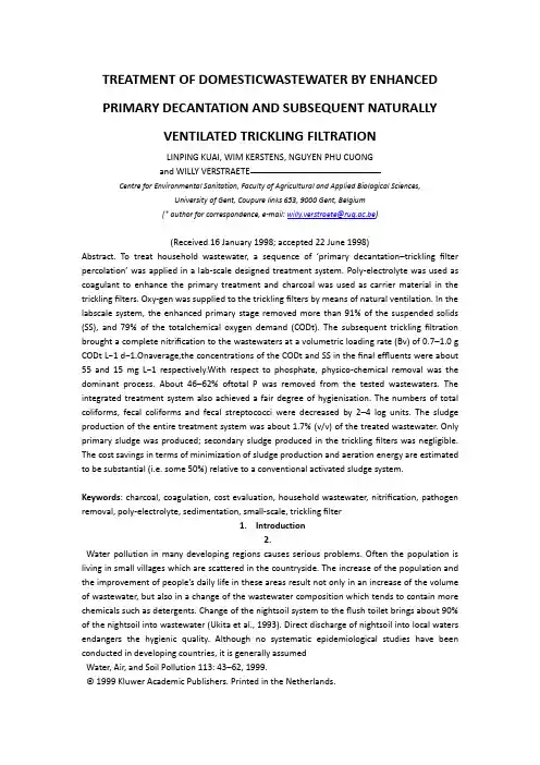
TREATMENT OF DOMESTICWASTEWATER BY ENHANCEDPRIMARY DECANTATION AND SUBSEQUENT NATURALLYVENTILATED TRICKLING FILTRATIONLINPING KUAI, WIM KERSTENS, NGUYEN PHU CUONGand WILLY VERSTRAETECentre for Environmental Sanitation, Faculty of Agricultural and Applied Biological Sciences,University of Gent, Coupure links 653, 9000 Gent, Belgium(* author for correspondence, e-mail: willy.verstraete@rug.ac.be)(Received 16 January 1998; accepted 22 June 1998)Abstract. To treat household wastewater, a sequence of ‘primary decantation–trickling filter percolation’ was applied in a lab-scale designed treatment system. Poly-electrolyte was used as coagulant toenhance the primary treatment and charcoal was used as carrier material in the trickling filters. Oxy-gen was supplied to the trickling filters by means of natural ventilation. In the labscale system, theenhanced primary stage removed more than 91% of the suspended solids (SS), and 79% of the totalchemical oxygen demand (CODt). The subsequent trickling filtration brought a complete nitrificationto the wastewaters at a volumetric loading rate (Bv) of 0.7–1.0 g CODt L−1 d−1.Onaverage,theconcentrations of the CODt and SS in the final effluents were about 55 and 15 mg L−1 respectively.With respect to phosphate, physico-chemical removal was the dominant process. About 46–62% oftotal P was removed from the tested wastewaters. The integrated treatment system also achieved a fairdegree of hygienisation. The numbers of total coliforms, fecal coliforms and fecal streptococci weredecreased by 2–4 log units. The sludge production of the entire treatment system was about 1.7%(v/v) of the treated wastewater. Only primary sl udge was produced; secondary sludge produced in thetrickling filters was negligible. The cost savings in terms of minimization of sludge production andaeration energy are estimated to be substantial (i.e. some 50%) relative to a conventional activatedsludge system.Keywords: charcoal, coagulation, cost evaluation, household wastewater, nitrification, pathogenremoval, poly-electrolyte, sedimentation, small-scale, trickling filter1.Introduction2.Water pollution in many developing regions causes serious problems. Often thepopulation is living in small villages which are scattered in the countryside. Theincrease of the population and the improvement of people’s daily life in these areasresult not only in an increase of the volume of wastewater, but also in a changeof the wastewater composition which tends to contain more chemicals such asdetergents. Change of the nightsoil system to the flush toilet brings about 90% ofthe nightsoil into wastewater (Ukita et al., 1993). Direct discharge of nightsoil intolocal waters endangers the hygienic quality. Although no systematic epidemiological studies have been conducted in developing countries, it is generally assumedWater, Air, and Soil Pollution 113: 43–62, 1999.© 1999 Kluwer Academic Publishers.Printed in the Netherlands.44LINPING KUAI ET AL.that the direct discharge of raw nightsoil is responsible for a high risk of infectiousdisease transmission in many rural regions of the developing countries (Schertenleib, 1995). Water shortage in arid and semi arid areas can necessitate the reuseof wastewater for local irrigation (Mandi et al., 1993). Treatment of this potentialresource is imperative to avoid sanitary risks before re-use (Hespanhol, 1990).The main objective of wastewater treatment is to dispose the treated effluentwithout causing an adverse impact on the ecosystem of the receiving water body.For this reason sewage treatment always includes the reduction of the concentrationof at least one of the four most important constituents of sewage: (1) suspendedsolids; (2) organic matter; (3) nutrients (notably nitrogen and phosphorus); and(4) pathogenic organisms (Van Haandel and Lettinga, 1994). Up to now, the western model of sewage treatment is the dominant one leading the environmental technological development over the world. However, the techniques which havebeen developed to achieve high levels of N and P removal, might not be applicablein many developing countries because of limited financial and energy resourcesavailable (Larsen and Gujer, 1997; Netter et al., 1993). Yet, since agriculture re-quires a substantial amount of water and nutrient input, safe reuse of treated sewagein these regions can free high quality water for other purposes and can supplementchemical fertilizers. Efficient use of resources will lead to a minimal increase ofentropy and will require an active rather than a reactive approach (Larsen andGujer, 1997). It is therefore of importance in many developing areas to treat sewageto the extend that it can be safely reused on the land. If the wastewater has to bedischarged to the local water-bodies, it should be treated so that the quality ofthe receiving water can be maintained at a level for safe drinking with no risk ofpathogens, no bad smell, no depletion of O2 and no toxicity from NHC4 or NH3.Hence, removal of pathogens and organic matter, in addition to achieving a highlevel of nitrification are essential.Centralized sewage treatment plants are generally not suitable for rural areas.Collection of domestic wastewater and transport to a distant treatment plant isexpensive at low population density (Netter et al., 1993; Paulsrud and Haraldsen,1993). On-site treatment using small scale wastewater treatment plants is the mostcost-effective alternative. The treatment technology for small wastewater streamsshould be based on locally available and serviceable materials and equipments thatare simple and economical to operate. Those low technical skills needed are the most appropriate ones (Ødegaard, 1997). A primary settling tank combined witha t rickling filter based on natural materials and natural ventilation might be anappropriate solution for water pollution control in most rural areas, especially indeveloping countries. The small-scale treatment unit designed for individual house holds or small communities can be compact and closed without causing negativeimpact on the landscape and without producing noise or odors. It can handle fluctuations in hydraulic and organic loads without variation in removal efficiencies(D’Antonio et al., 1997).TREATMENT OF DOMESTICWASTEWATER 45TABLE IThe main characteristics of the two types of wastewater(Average Standard deviation)Parameter UnitThe MHWThe SHWCODtmg L−1 500.0±376 2865.0±3822CODs mg L−1 161.0±42 205.0±134SS mg L−1 673.0±425 2555.0±3103Total N mg L−1 41.0±13 204.0±161Kj-N mg L−1 41.0±13 202.0±161NHC4 -N mg L−1 30.0±1063.0±28NOx−-N mg L−1 0.0 2.03Total Pmg L−1 8.0±3 26.0±13PO3C4 –Pmg L−1 4.0±3 13.0±4pH 7.2±0.4 7.7±0.3The purpose of our research was to develop a treatment process that will guarantee the technical asibility in rural areas, taking into consideration factors suchas the construction and maintenance costs, the availability of construction materialsand equipment, the limitation of land for anindividual household, the productionof noise and odor as well as specialized labor and skills, especially for developingcountries.2. Materials and Methods2.1. WASTEWATERTwo types of domestic wastewaters were tested in the experiments. One was amultiple households wastewater (MHW) obtained from a municipal wastewatertreatment plant located in Gent, Belgium. The other was a single household wastewater (SHW) collected from a family living in the rural area of Avelgem, Belgium.The wastewater samples were taken generally once a week from the sites andstoredat 4 C in the lab before feeding. The main characteristics of the wastewaters aregiven in Table I. The SHW was about 3 times more concentrated than the MHWbecause the water consumption of the family was relatively low and rainfall wasnot entering the wastewater collecting system. Instead of 180 L per inhabitantequivalent (I.E.) per day, discharged to the municipal wastewater treatment plant,the family only discharged maximally 70 L (I.E.)−1d−146LINPING KUAI ET AL.2.2EXPERIMENTS2.2.1. Integrated Treatment of the Multiple Households WastewaterThe process diagram used for the treatment of the MHW is illustrated in Figure 1.The lab-scale integrated system consisted of an influent tank of 30 L, a primarysettling tank of 6 L and a na turally ventilated trickling filter of 2.5 L. To enhancethe natural aeration, as illustrated in Figure 2, the trickling filter was modified basedTREATMENT OF DOMESTICWASTEWATER 47on a conventional trickling filter by placing a net column inside to improve the O2supply. This inner net column was made with PVC and about 80% of the wall areawas holes with 1 cm in diameter. The dimensions of the modified trickling filterwere 1.0 m in height, 0.08 m in diameter of the outside PVC column and 0.056 mof the inside net column. A commercial charcoal (Charbon de bois Epure, S. A.Delhaize, Brussels, Belgium) was used as carrier material, it was grinded toparticles with diameter of about 2 cm before use. Aeration occurred via natural contactwith air entering through the inside net column. Supplemental forced aeration wasnot imposed.The raw MHW was batch fed into the influent tank once a day. It was pumpedsemi-continuously from the influent tank into the primary settling tank in upwarddirection, i.e. 10 min every 15 min. During the pumping period, the influent was si-multaneously mixed by a mixer to avoid accumulation of solids in the influent tank.Chemical coagulation was not applied in the primary stage. The supernatant fromthe primary settling tank automatically flowed into the subsequent trickling filterby gravity force. It percolated over the carrier in downward direction. Operation ofthe trickling filter was started at a low loading rate. The loading rate was increasedstep-wise during the first few weeks depending on the removal e fficiencies of totalchemical oxygen demand (CODt) and NHC4 -N. After an adaptation period of 4weeks, the flow rate was controlled around 25 L d−1, and the HRTs (hydraulicretention time) of the primary settling tank and the trickling filter were 5.8 and2.4 hr, respectively. The volumetric loading rate (Bv) of the trickling filter wasabout 1.0 g COD L−1d−1corresponding to 0.35 g Kj-N L−1d−1(based on theCODt and Kj-N concentrations of the outflow from the primary settling tank). During the whole experimental period, the integrated treatment system was operated atroom temperature varying around 20 C.2.2.2. Integrated Treatment of the Single Household Wastewater2.2.2.1. (a). Primary Coagulation and Sedimentation Tests Before operation ofthe integrated treatment system, a jar test using chemical coagulation and sedimentation to pre-treat the highly concentrated wastewater was carried out. Polyelectrolyte (Praestol BC 611, ChemischeFabrik Stockhausen Gmbh, Krefeld, Germany) was used as the coagulant. Five different dosages of poly-electrolyte, namely0, 2.5, 5, 7.5, 10 mg L−1, were tested. The wastewater sample (800 mL) and theneeded amount of the poly-electrolyte stock solution (1 g L−1) were added into1000 mL beakers. After mixing at 250 rpm for 2 min, the mixed liquors wereallowed to settle for 30 min and the supernatants were taken for analyses. The testswere performed twice with samples obtained at two different times.2.2.2.2. (b). Operation of the Integrated T reatment System The process diagramof the integrated system operated for the SHW was similar to the one used for theMHW treatment. However, the individual treatment units were slightly different.The volume of the influent tank and the primary settling tank were smaller, only48 LINPING KUAI ET AL.10 and 4 L, respectively. The employed trickling filter was a conventional tricklingfilter constructed with a PVC column with a total volume of 2 L, 1.0 m in heightand 0.05 m in diameter. The detailed structure is demonstrated in Figure 1. Freshcharcoal, grinded and sieved to a particle size of about 2 cm, was used as carriermaterial. On the top of the trickling filter, a layer of 10 cm of crushed stones with0.5 to 1 cm in diameter, was placed in order to improve the influent distribution.About 8 small holes, with 1 cm in diameter each, were scattered on the wall of thePVC column close to the bottom. Aeration occurred via contact with air enteringthrough the aeration holes.Based on the results of the primary coagulation and sedimentation tests, chemical coagulation was applied in the primary treatment stage for this highly con centrated SHW. The raw SHW and about 5 mg L−1of poly-electrolyte (PraestolBC 611) were batch added into the influent tank once a day. They were mixed inthe influent tank and pumped into the primary settl ing tank in upward direction simultaneously, for 10 min in every 15 min. The consequential treatment procedureswere similar to those applied for the MHW treatment. After an adaptation periodof 4 weeks, the flow ratewas controlled around 10 L d−1. The Bv of the tricklingfilter fluctuated around 0.7 g CODt L−1d−1which was about 30% lower than theone applied for the MHW treatment. The nitrogen loading rate was about 0.3 gKj-N L−1d−1. The HRT was about 9.6 hr in the primary settling tank and 4.8 hr inthe trickling fil ter. The primary sludge was removed at intervals from the primarysettling tank, e.g. once every two weeks. The system was also operated at roomtemperature around 20 C.2.3. ANALYSESThe routine analyses were carried out once a week unless stated otherwise. Theinfluent and effluent samples were collected proportionally everyday and stored at4 C until analyses. The parameters of COD, Kj-N (Kjeldahl-N), NHC4 -N, NOx -N,andPt (total P) were determined in accordance to the Standard Methods (APHAet al., 1992). Total coliform (TC), fecal coliform (FC) and fecal streptococci (FS)were enumerated by plate count techniques as described by Kersters et al. (1995).3. ResultsThe treatment performance of the laboratory integrated systems were monitoredby determining the removal of (1) suspended solid; (2) organic materials (CODt);(3) nutrients (N and P); and (4) pathogenic organisms (TC, FC and FS).TREATMENT OF DOMESTICWASTEWATER 49TABLE I IThe results of the jar tests on the raw SHW3.1. CODt AND SS REMOVAL3.1.1. Primary Jar Tests to Pre-Treat the SHW by Coagulation and SedimentationThe results of the jar tests by coagulation and sedimentation are described in Table II. For the concentrated SHW, simple sedimentation gave an insufficient andunstable removal of COD t which varied from 23 to 73%. The poly-electrolyteshowed to be highly effective to enhance the CODt removal. By adding 5 mg L−1of poly-electrolyte, the removal percentage of CODt increased to 93%.3.1.2. The Integrated SystemThe change of the CODt concentrations during the whole experimental period areshown in Figure 3. The influent CODt and SS in both types of wastewaters variedconsiderably. For the SHW, up to 15700 mg L−1of CODt was measured in week15 coupled with a high SS concentration of 11200 mg L−1. The variation of theMHW was slightly lower because the wastewater was taken after a grit chamberwhere large particles had already been removed. However, as shown in Figure 3,the influent CODt was still often up to 1000 mg L−1, which was 2 times as high asi tsmean value.The high CODt mainly resulted from the high SS concentration. The primarytreatments removed the major part of CODt and SS from both types of wastewaters.As indicated in Table III, although in the treatment of MHW, poly-electrolyte wasnot used in the primary stage, straight-forward sedimentation still removed 79% ofCODt and 91% of SS, leaving a stable CODt concentration in the effluent rangingfrom 80 to 250 mg L−1. For the SHW, combination of chemical coagulation andsedimentation could even remove up to 95% of CODt and 99% of SS, respectively.Fluctuation of the loading rates was successfully smoothed. The effluent after theprimary stage had a relatively stable concentration of CODt, mostly between 100to 200 mg L−1.The subsequent trickling filters polished the outflows from the primary settlingtanks to a high quality. The final effluents of the MHW and SHW contained a lowCODt concentration of 55 and 50 mg L−1as well as a low SS concentration of 17and11mgL−1in average, respectively.50 LINPING KUAI ET AL.Figure 3.The concentration of CODt in the different process stages. A) The multiple households wastewater; B) The single household wastewater.In total, the entire processes removed respectively about 98% of CODt and 99%of SS fromthe SHW, and about 89% of CODt and 98% of SS from the MHW.3.2. REMOVAL OF NITROGENThe concentrations of nitrogen compounds in the different treatment processes areindicated in Figure 4. The removal percentages are listed in Table IV. As shown inTable IV, for both types of wastewaters, the pri mary treatments were shown sufficient for organic N removal but not for NHC-N removal. For the MHW, the singlesedimentation stage removed about 15% of the Kj-N which was totally due to theremoval of organic N. Of the residual Kj-N in the outflow, 9% was contributedby organic N. For the SHW, about 69% of Kj-N was removed in which only 3%was due to the removal of NHC4 -N. The primary coagulation and sedimentationremoved almostall the organic N.Of the residual Kj-N in the outflow, only 1.6%came from organic N.The trickling filters converted the residual Kj-N mainly to NO−x -N by means ofnitrification. Figure 5 shows that the two trickling filters were all characterized bya start-up period of about 3 weeks with a limited efficiency of nitrification for bothtypes of wastewaters. Significant decrease of NHC4 -N concentration and increase ofNO−x -N concentration in the effluents of the trickling filter occurred simultaneouslyfrom week 3 onwards. After an adaptation period of about 4 weeks, the removalrates of NHC4 -N in the trickling filters increased to 0.30 and 0.25 g NHC4 -N L−1Figure 4.The change of N concentration in the different treatment stages. A) The multiple householdswastewater; B) The single household wastewater.d−1for the MHW and SHW, respectively. On average, about 60% of NHC4 -N wasconverted to NOxN from the MHW and 75% from the MHW.The total N removal was different for the two types of wastewaters. For theMHW, the entire system removed about 49%of total N, in which 15%was removedby the primary sedimentation and another 34% was contributed by the tricklingfilter as partial denitrification occurred in the reactor. The final effluent of theMHW contained 3 mg L−1ofKj-Nand18mgL−1of NO−x -N. For the SHW,the primary coagulation and sedimentation processes removed about 69% of theotal N. However, only a very limited removal of total N, about 2%, was achievedTREATMENT OFin the trickling filter. The final effluent of the SHW contained about 14 mgL−1ofKj-Nand46mgL−1of NO−x -N, respectively.3.3. REMOVAL OF PHOSPHORUSor both types of wastewaters, removal of total phosphorus (Pt) was stable duringhe whole experimental period. As shown in Table V, Pt was mainly removed inhe primary stage. Physico-chemical removal of Pt was the dominant pathway. Inotal, the removal of Pt was about 49% from the MHW and 62% from the SHW.The residual Pt in the final effluents was about 4 and 10 mg L−1, respectively.3.4. HYGIENEThe removal of pathogens from the two wastewaters by the integrated treatmentas quite similar. As shown in Table VI, a fair degree of hygienisation was achieved.n total, the numbers of total coliforms (TC), fecal coliforms (FC) and fecal streptococci (FS) were reduced by 2–4 log units. The reduction was mainly broughtbout by the trickling filters.TREATMENT OF DOMESTICWASTEWATER 553.5. SLUDGE PRODUCTION3.5.1. Primary SludgeThe MHW was less concentrated than the SHW and chemical coagulation wasot imposed in the primary stage. Therefore, sedimentation of the MHW did notprodu ce much sludge. In the first 2 months, the volume of the sludge accumulatedin the primary settling tank increased slowly to 4 L. After that, increase of thesludge volume did not proceed. During the whole operational period of 5 months,there was no need to discharge sludge from the primary settling tank. For the SHW,the primary coagulation and sedimentation stage produced about 1.7% (v/v) ofsludge relative to the total flow of the raw wastewater. The sludge produced wasregularly withdrawn from the primary settling tank once every two weeks. Thewaste sludge was a mixture of under-flow and skimmed floating material and hada concentration of 40 to 50 g SS L−1.3.5.2. Secondary Sludge Secondary sludge produced in the trickling filters was negligible for the two typeso f wastewaters. This was reflected by the low SS concentrations in the effluents;a secondary decanter was not necessary. The two test-runs revealed that the integrated system was stable in operation over an observation period of more than 5months under the given lab-scale conditions. Clogging was never experienced inthe trickling filters.4. Discussion4.1. COAGULATION AND SEDIMENTATIONIn practice, both the quantity and quality of wastewater can vary drastically. It iswell known that the smaller the population, the more pronounced the variation.Whereas larger cities exhibit a variation factor, defined as maximum load/meanload of 1.5–2, the factor may be as high as 5 in small domestic residential areas(Markus, 1997). Therefore, the dynamics of flow and load variations ask for equalization and pretreatment. Especially, when applying high rate treatment systemswith short retention times such as trickling filters and rotating biological contactors, a stable loading rate is an important prerequisite for satisfactory treatmentperformance. Pretreatment also ensures the high quality of the final effluent. Itcan effectively remove the recalcitrant COD fraction as this fraction is mainlyassociated with particles and colloids (Yoshimasa and Yoshihiko, 1997; Rustenet al., 1997).In the treatment of theMHWwith the integrated system, during the first 3 weeksof operating, the COD removal by the simple sedimentation step was not as goodas the one combined with coagulation in the treatment of the SHW (Figure 3).However, from week 4 onwards when enough amount of sludge was accumulated56 LINPING KUAI ET AL.in the primary settling tank and the sludge bed had built up, increase of the CODtremoval was observed. This fact indicated that the sludge bed could serve as asorption layer capturing particles and colloids effectively.For the SHW, the primary jar tests with coagulation and sedimentation showedthat for the concentrated SHW, simple sedimentation was insufficient and unstableto buffer the high variation of the wastewater (T able II). This poor and variableperformance was mainly due to the poor settling characteristics of the SHW.Whenthe wastewater contained much toilet wastes, which also happened frequently during the experimental period, it became very turbid with colloids and settled poor ly.Yet, by adding 5 mg L−1of poly-electrolyte, the removal of the CODt increasedto 93%. This clearly indicated that combination of coagulation and sedimentationwas necessary to ensure a high and stable performance of the primary settling tank.During the operation of the integrated treatment system, the high performance andthe considerable equilibrium capacity of the primary coagulation and sedimentation processes were furtherconfirmed (Figure 3). Not only did it remove about79–95% of CODt, but also absorbed the peak CODt, which varied from 240 to15800 mg L−1. Consequently, the influence of a shock load to the downstreamtrickling filter was alleviated and a high performance was guaranteed.The hydraulic retention time of about 6–10 hr in the two primary settling tankswas relatively long compared with a normal primary settling time of 1–2 hours.The reason of applying the large primary settling tanks was to make them functionboth as primary sludge separation and sludge storage tanks. Long time retention ofsludge in the primary settling tanks, especially in the case of the MHW treatment,resulted in sludge hydrolysis and digestion. Because of sludge hydrolysis and digestion, the sludge production was reduced and a slightly increase of the NHC4 –Nconcentration in the effluent, from 30 to 32 mg L−1, was observed (Figure 4).4.2. TRICKLING FILTERA trickling filter purifies wastewater through physical filtration/adsorption and bi ological degradation. Generally, at least two biological processes are involved ina trickling fil ter, i.e. COD degradation and nitrification. In some cases, partialdenitrification occurs simultaneously (Bertanza, 1997).During the experimental period of 5 months, the effluent CODt from the twotrickling filters remained below 70 mg L−1. Mostly, they were below 60 mg L−1.Without a secondary decanter, the SS concentration in the effluents was around10–20 mg L−1, which indicated that sludge production in the trickling filters wasnegligible. Based on the above fact, backwashing of the trickling filters was notnece ssary. In comparison, a survey of 43 small Norwegian activated sludge plantswith co-precipitation showed a median effluent COD concentration of 70 mg L−1 andSSof24mgL−1(Rusten et al., 1997). The nitrification capacity in the two testruns reached 0.2–0.3 g Kj-N L−1d−1at a Bv of 0.7–1.0 g COD L−1d−1(Figure 4).It was equivalent to or even higher than that in a conventional activated sludgeTREATMENT OF DOMESTICWASTEWATER 57system working at a low loading rate (Muller et al., 1995). Similar results werereported by Netter et al. (1993). However, the latter authors applied a loading rateto the biofilter of only 0.1–0.2 g COD L−1d−1and forced aeration was supplied.An important aspect of the biological processes in a trickling filter is the oxygensupply. In theory, oxygen diffusion from gas to liquid, and then from liquid tobiomass surface is much slower than diffusion from gas phase to biomass surfacedirectly (Tijhuis, 1994). Biomass in a trickling filter can only gain oxygen from airin the open spaces. Gas transport i s the limiting process in all types of biologicallyactive filters (Schwager and Boller, 1997). The trickling filters used in this work,especially the modified one with an inner net column, created good conditions for air supply. The low hydraulic loading rate, obtained by not applying recirculation, avoided liquid flooding. Without liquid resistance, high efficiency of oxygentransfer was ensured. Therefore, the oxygen supply, based solely on the naturalventilation through the aeration holes or the inner net was satisfactory. The latterwas demonstrated by the efficient COD removal, the negligible sludge productionand the effective nitrification.Charcoal has been widely used as an adsorbent in the wastewater treatment (Abeet al., 1993; Funke et al., 1994; Abe et al., 1993; Khalfaoui et al., 1995) because itssurface characteristics are similar to those of granular activated carbon. However,its application as carrier material in a biofilm reactor was scarcely reported. Besideshaving many essential properties, such as a high specific surface area and a highvoid ratio, being durable and light-weight, a maxtrixto be used for sewage treatment in rural areas should also be cheap and locally available. Charcoal, the supportused in the tested trickling filters, fulfilled the abov e requirements. It can be easilycrushed to a required particle size, i.e. 2 to 3 cm. The low density of charcoal, lessthan 1 kg cm−3, makes it more favorable than other materials such as crushed rock,slag etc. With many micro-pores on the surface, charcoal provides good conditionsfor micro-organisms to attach. Fresh charcoal is also a good adsorbent which canaccumulate sufficient organic matter and nutrients for biomass to grow. During thefirst few weeks before the biofilm builds up, the adsorption can also c ompensate theinsufficient biodegradation of COD. Therefore, it can ensure a low effluent CODduring the whole experimental period (Figure 3).In a nitrifying trickling filter, removal of total N can occ ur through the simultaneous denitrification in the anoxic micro-zones within the biological floc (Bertanza,1997). As noted in Table IV, the two trickling filter test-runs showed differentperformance for total N removal from the two types of wastewaters. During thetreatment of the SHW, the trickling filter only converted NHC4 -N to NOx -N withoutdenitrification. However, in the treatment of the MHW, trickling filtration is considered to remove 34% of the total N by means of denitrification. The differencewas due to two factors. One was the different loading rates (Bv) applied to the two trickling filters. The former was treated under a low Bv, e.g., 0.7 g COD L−1d−1,while the latter was treated at a relatively high Bv of 1.0 g COD L−1d−1. The higherBv might create more anoxic micro-zones in the filter which allow denitrification58 LINPING KUAI ET AL.to occur. The other factor was the different ratio of CODt:Kj-N in the influents ofthe two trickling filters. The former had a ratio of 2.2, while the latter had a ratio of3.3. The higher COD:Kj-N ratio resulted in the higher denitrification driving force(Watanabe, et al., 1995).Drawbacks of the system are the absence of an effective denitrification and Premoval. In regions where local soil is poor in nutrients and agricultural fertilizersare relatively expensive or scarce, the so treated sewage could be used for irrigationand fertilization. In industrialized countries however, further improvement of thedenitrification and P removal processes is necessary in order to make this integratedsystem acceptable for implementation in rural areas.4.3. HYGIENEPrimary or secondary wastewater treatment systems generally have poor disinfecting capacity. According to Block (1982) and Farrell et al. (1990), the removalefficiency of fecal coliforms (FC) can only reach 60 to 99% in a con ventionalactivated sludge or a biofilm process. Tremblay et al. (1996) reported that about56% reduction of FC was observed in their trickling bio-filtration process. Our twotrickling filter test-runs disinfected the wastewater fairly well after the adaptationperiods. They reduced the total coliforms (TC), fecal coliforms (FC) and fecalstreptococci (FS) by 2–4 log units. The residual TC in the effluents was less than1000 TC per 100 mL (Table VI). According to the guidelines of microbiologicalquality for irrigation posted by the World Health Organization (WHO), i.e. <1000TC per 100 mL, the treated wastewaters can be used for irrigation of all cropswithout further disinfection (Janssens and Verstraete, 1996; Ghrabi et al., 1993).The main principle of disinfection by a biological process is believed to be basedon sorption, die-off and the predation of micro-organisms by macro-organisms.The high variety of macro-organisms in the trickling filters might be the majorcontributor to the good effect of disinfection. However, the disinfection appearedsimultaneously with nitrification. This fact was in good agreement with the findingsof Lens et al. (1994). The good disinfection effect of their peat。
中英文资料对照外文翻译Catalytic strategies for industrial water re-useAbstractThe use of catalytic processes in pollution abatement and resource recovery is widespread and of significant economic importance [R.J. Farrauto, C.H. Bartholomew, Fundamentals of Industrial Catalytic Processes, Blackie Academic and Professional,1997.]. For water recovery and re-use chemo-catalysis is only just starting to make an impact although bio-catalysis is well established [J.N. Horan, BiologicalWastewater Treatment Systems; Theory and Operation, Chichester, Wiley, 1990.]. This paper will discuss some of the principles behind developing chemo-catalytic processes for water re-use. Within this context oxidative catalytic chemistry has many opportunities to underpin the development of successful processes and many emerging technologies based on this chemistry can be considered .Keywords: COD removal; Catalytic oxidation; Industrial water treatment1.IntroductionIndustrial water re-use in Europe has not yet started on the large scale. However, with potential long term changes in European weather and the need for more water abstraction from boreholes and rivers, the availability of water at low prices will become increasingly rare. As water prices rise there will come a point when technologies that exist now (or are being developed) will make water recycle and re-use a viable commercial operation. As that future approaches, it is worth stating the most important fact about wastewater improvement–avoid it completely if at all possible! It is best to consider water not as a naturally available cheap solvent but rather, difficult to purify, easily contaminated material that if allowed into the environment will permeate all parts of the biosphere. A pollutant is just a material in the wrong place and therefore design your process to keep the material where it should be –contained and safe. Avoidance and then minimisation are the two first steps in looking at any pollutant removal problem. Of course avoidance may not be anoption on an existing plant where any changes may have large consequences for plant items if major flowsheet revision were required. Also avoidance may mean simply transferring the issue from the aqueous phase to the gas phase. There are advantages and disadvantages to both water and gas pollutant abatement. However, it must be remembered that gas phase organic pollutant removal (VOC combustion etc.,) is much more advanced than the equivalent water COD removal and therefore worth consideration [1]. Because these aspects cannot be over-emphasised,a third step would be to visit the first two steps again. Clean-up is expensive, recycle and re-use even if you have a cost effective process is still more capital equipment that will lower your return on assets and make the process less financially attractive. At present the best technology for water recycle is membrane based. This is the only technology that will produce a sufficiently clean permeate for chemical process use. However, the technology cannot be used in isolation and in many (all) cases will require filtration upstream and a technique for handling the downstream retentate containing the pollutants. Thus, hybrid technologies are required that together can handle the all aspects of the water improvement process[6,7,8].Hence the general rules for wastewater improvement are:1. Avoid if possible, consider all possible ways to minimise.2. Keep contaminated streams separate.3. Treat each stream at source for maximum concentration and minimum flow.4. Measure and identify contaminants over complete process cycle. Look for peaks, which will prove costly to manage and attempt to run the process as close to typical values as possible. This paper will consider the industries that are affected by wastewater issues and the technologies that are available to dispose of the retentate which will contain the pollutants from the wastewater effluent. The paper will describe some of the problems to be overcome and how the technologies solve these problems to varying degrees. It will also discuss how the cost driver should influence developers of future technologies.2. The industriesThe process industries that have a significant wastewater effluent are shown in Fig. 1. These process industries can be involved in wastewater treatment in many areas and some illustrations of this are outlined below.Fig. 1. Process industries with wastewater issues.2.1. RefineriesThe process of bringing oil to the refinery will often produce contaminated water. Oil pipelines from offshore rigs are cleaned with water; oil ships ballast with water and the result can be significant water improvement issues.2.2. ChemicalsThe synthesis of intermediate and speciality chemicals often involve the use of a water wash step to remove impurities or wash out residual flammable solvents before drying.2.3. PetrochemicalsEthylene plants need to remove acid gases (CO2, H2S) formed in the manufacture process. This situation can be exacerbated by the need to add sulphur compounds before the pyrolysis stage to improve the process selectivity. Caustic scrubbing is the usual method and this produces a significant water effluent disposal problem.2.4. Pharmaceuticals and agrochemicalsThese industries can have water wash steps in synthesis but in addition they are often formulated with water-based surfactants or wetting agents.2.5. Foods and beveragesClearly use water in processing and COD and BOD issues will be the end result.2.6. Pulp and paperThis industry uses very large quantities of water for processing –aqueous peroxide and enzymes for bleaching in addition to the standard Kraft type processing of the pulp. It is important to realise how much human society contributes to contaminated water and an investigation of the flow rates through municipal treatment plants soon shows the significance of non-process industry derived wastewater.3. The technologiesThe technologies for recalcitrant COD and toxic pollutants in aqueous effluent are shown in Fig. 2. These examples of technologies [2,6,8] available or in development can be categorised according to the general principle underlying the mechanism of action. If in addition the adsorption (absorption) processes are ignored for this catalysis discussion then the categories are:1. Biocatalysis2. Air/oxygen based catalytic (or non-catalytic).3. Chemical oxidation1. Without catalysis using chemical oxidants2. With catalysis using either the generation of _OH or active oxygen transfer. Biocatalysis is an excellent technology for Municipal wastewater treatment providing a very cost-effective route for the removal of organics from water. It is capable of much development via the use of different types of bacteria to increase the overall flexibility of the technology. One issue remains –what to do with all the activated sludge even after mass reduction by de-watering. The quantities involved mean that this is not an easy problem to solve and re-use as a fertilizer can only use so much. The sludge can be toxic via absorption of heavy metals, recalcitrant toxic COD. Inthis case incineration and safe disposal of the ash to acceptable landfill may be required. Air based oxidation [6,7] is very attractive because providing purer grades of oxygen are not required if the oxidant is free. Unfortunately, it is only slightly soluble in water, rather unreactive at low temperatures and, therefore, needs heat and pressure to deliver reasonable rates of reaction. These plants become capital intensive as pressures (from _10 to 100 bar) are used. Therefore, although the running costs maybe low the initial capital outlay on the plant has a very significant effect on the costs of the process. Catalysis improves the rates of reaction and hence lowers the temperature and pressure but is not able to avoid them and hence does not offer a complete solution. The catalysts used are generally Group VIII metals such as cobalt or copper. The leaching of these metals into the aqueous phase is a difficulty that inhibits the general use of heterogeneous catalysts [7]. Chemical oxidation with cheap oxidants has been well practised on integrated chemical plants. The usual example is waste sodium hypochlorite generated in chlor-alkali units that can be utilised to oxidise COD streams from other plants within the complex. Hydrogen peroxide, chlorine dioxide, potassium permanganate are all possible oxidants in this type of process. The choice is primarily determined by which is the cheapest at the point of use. A secondary consideration is how effective is the oxidant. Possibly the most researched catalytic area is the generation and use of _OH as a very active oxidant (advanced oxidation processes) [8]. There are a variety of ways of doing this but the most usual is with photons and a photocatalyst. The photocatalyst is normally TiO2 but other materials with a suitable band gap can be used [9,10]. The processes can be very active however the engineering difficulties of getting light, a catalyst and the effluent efficiently contacted is not easy. In fact the poor efficiency of light usage by the catalyst (either through contacting problems or inherent to the catalyst) make this process only suitable for light from solar sources. Photons derived from electrical power that comes from fossil fuels are not acceptable because the carbon dioxide emission this implies far outweighs and COD abatement. Hydroelectric power (and nuclear power) are possible sources but the basic inefficiency is not being avoided. Hydrogen peroxide and ozone have been used with photocatalysis but they can be used separately or together with catalysts to effect COD oxidation. For ozone there is the problem of the manufacturing route, corona discharge, which is a capital intensive process often limits its application and better route to ozone would be very useful. It is important to note at this point that the oxidants discussed do not have sufficient inherent reactivity to be use without promotion. Thus, catalysis is central to their effective use against both simple organics (often solvents) or complex recalcitrant COD. Hence, the use of Fenton’s catalyst (Fe) for hydrogen peroxide [11]. In terms of catalysis these oxidants together with hypochlorite form a set of materials that can acthas ‘active oxygen transfer (AOT) oxidants’ in the presence of a suitable catalyst. If the AOT oxidant is hypochlorite or hydrogen peroxide then three phase reactions are avoided which greatly simplifies the flowsheet. Cheap, catalytically promoted oxidants with environmentally acceptable products of oxidation that do not require complex chemical engineering and can be produced efficiently would appear to offer one of the best solutions to the general difficulties often observed.3.1. Redox catalysis and active oxygen transferThe mechanism of catalytically promoted oxidation with hydrogen peroxide or sodium hypochlorite cannot be encompassed within one concept, however there are general similarities between the two oxidants that allows one to write a series of reactions for both (Fig. 3) [5]. This type of mechanism could be used to describe a broad range of reactions for either oxidant from catalytic epoxidation to COD oxidation. The inherent usefulness of the reactions is that;1. The reactions take place in a two-phase system.2. High pressure and temperature are not required.3. The catalytic surface can act as an adsorbent of the COD to be oxidised effectively increasing the concentration and hence the rate of oxidation.The simple mechanism shows the selectivity issue with this type of processes. The oxidant can simply be decomposed by the catalyst to oxygen gas – this reaction must be avoided because dioxygen will play no role in COD removal. Its formation is an expensive waste of reagent with oxygen gas ($20/Te) compared to the oxidant ($400–600/Te). To be cost competitive with alternative processes redox catalysis needs excellent selectivity.3.2. Technology mappingThe technologies so far described can be mapped [12] for their applicability with effluent COD concentration (measured as TOC) and effluent flow rate (m3 h-1). The map is shown in Fig. 4. The map outlines the areas where technologies are most effective. The boundaries, although drawn, are in fact fuzzier and should be only used as a guide. Only well into each shape will a technology start to dominate. The underlying cost model behind the map is based on simple assertions – at high COD mass flows only air/oxygen will be able to keep costs down because of the relatively low variable cost of the oxidant. At high COD concentrations and high flows only biological treatment plants have proved themselves viable –of course if done at source recovery becomes an option. At low flows and low COD levels redox AOT catalysis is an important technology – the Synetix Accent 1 process being an example of this type of process (see Fig. 5 for a simplified flowsheet). The catalyst operates under very controlled conditions at pH > 9 and hence metal leaching can be avoided (<5 ppb). The activity and selectivity aspects of the catalyst displayed in Fig. 3 can befurther elaborated to look at the potential surface species. This simple view has been extended by a significant amount of research [3,4,5]. Now the mechanism of such a catalyst can be described in Fig. 6. The key step is to avoid recombination of NiO holes to give peroxy species and this can be contrasted with the hydrogen peroxide situation where the step may be characterized as oxygen vacancy filled. From both recombination will be facilitated by electronic and spatial factors. The range of application of the process is outlined below. From laboratory data some general types of chemical have been found suitable –sulphides, amines, alcohols, ketones, aldehydes, phenols, carboxylic acids, olefins and aromatic hydrocarbons. From industrial trials recalcitrant COD (nonbiodegradable) and sulphur compounds have been successfully demonstrated and a plant oxidising sulphur species has been installed and is operational.4. ConclusionsWastewater treatment processes are in the early stages of development. The key parameters at present are effectiveness and long term reliability. Many processes operating are in this stage, including the redox Accent TM is a trademark of the ICI Group of Companies. catalysis systems. However,once proven, redox catalysis offers many advantages for COD removal from wastewater:1. The low capital cost of installation.2. Simple operation that can be automated.3. Flexible nature of the process – can be easily modified to meet changing demands of legislation.Hence it will be expected to develop into an important technology in wastewater improvement.AcknowledgementsThe author is grateful to Jane Butcher and Keith Kelly of Synetix for discussions on this paper. References[1] R.J. Farrauto, C.H. Bartholomew, Fundamentals of Industrial Catalytic Processes, Blackie Academic and Professional, 1997. F.E. Hancock / Catalysis Today 53 (1999) 3–9 9[2] J.N. Horan, Biological Wastewater Treatment Systems; Theory and Operation, Chichester, Wiley, 1990.[3] F.E. Hancock et al., Catalysis Today 40 (1998) 289.[4] F. King, F.E. Hancock, Catal. Today 27 (1996) 203.[5] J. Hollingworth et al., J. Electron Spectrosc., in press.[6] F. Luck, Environmental Catalysis, in: G. Centi et al. (Eds.), EFCE Publishers, Series 112, p. 125.[7] D. Mantzavinos et al., in: V ogelpohl and Geissen (Eds.), in: Proceedings of the Conference on Water Science and Technology, Clausthal-Zellerfeld, Germany, May 1996, J. Int. Assoc. Water Quality, Pergamon, 1997.[8] R. Venkatadri, R.W. Peters, Hazardous Waste Hazardous Mater. 10 (1993) 107.[9] A.M. Braun, E. Oliveros, Water Sci. Tech. 35 (1997) 17.[10] D. Bahnemann et al., Aquatic and surface photochemistry, Am. Chem. Soc. Symp. Ser. (1994) 261.[11] J. Prousek, Chem. Lisy 89 (1995) 11.工业废水回用的接触反应策略摘要:无论从控制污染还是资源恢复的角度,接触反应都是被广泛应用并极具经济效益的。
Nutrient removal in an A2O-MBR reactor with sludgereductionABSTRACTIn the present study, an advanced sewage treatment process has been developed by incorporating excess sludge reduction and phosphorous recovery in an A2O-MBR process. The A2O-MBR reactor was operated at a flux of 77 LMH over a period of 270 days. The designed flux was increased stepwise over a period of two weeks. The reactor was operated at two different MLSS range. Thermo chemical digestion of sludge was carried out at a fixed pH (11)and temperature (75℃) for 25% COD solubilisation. The released pbospborous was recovered by precipitation process and the organics was sent back to anoxic tank. The sludge digestion did not have any impact on COD and TP removal efficiency of the reactor. During the 270 days of reactor operation, the MBR maintained relatively constant transmembrane pressure. The results based on the study indicated that the proposed process configuration has potential to reduce the excess sludge production as well as it didn't detonated the treated water quality.Keywords: A2O reactor; MBR; Nutrient removal; TMP1. IntroductionExcess sludge reduction and nutrients removal are the two important problems associated with wastewater treatment plant. MBR process has been known as a process with relatively high decay rate and less sludge production due to much longer sludge age in the reactor (Wenet al., 2004). Sludge production in MBR is reduced by 28-68%, depending on the sludge age used (Xia et al.,2008). However, minimizing the sludge production by increasing sludge age is limited due to the potential adverse effect of high MLSS concentrations on membrane (Yoon et al., 2004). This problem can be solved by introducing sludge disintegration technique in MBR (Young et al., 2007). Sludge disintegration techniques have been reported to enhance the biodegradability of excess sludge (Vlyssides and Karlis, 2004). In overall, the basis for sludge reduction processes is effective combination of the methods for sludge disintegration and biodegradation of treated sludge. Advances in sludge disintegration techniques offer a few promising options including ultrasound (Guo et al., 2008), pulse power (Choi et al.,2006), ozone (Weemaes et al., 2000), thermal (Kim et al., 2003), alkaline (Li et al., 2008) acid (Kim et al., 2003) and thermo chemical(Vlyssides and Karlis, 2004). Among the various disintegration techniques, thermo chemical was reported to be simple and cost effective (Weemaes and Verstraete, 1998). In thermal-chemical hydrolysis, alkali sodium hydroxide was found to be the most effective agent in inducing cell lysis (Rocker et al., 1999). Conventionally, the nutrient removal was carried out in an A2O process. It has advantage of achieving, nutrient removal along with organic compound oxidation in a single sludge configuration using linked reactors in series (Tchobanoglous et al., 2003). The phosphoroes removal happens by subjecting phosphorous accumulating organisms (PAO) bacteria under aerobic and anaerobic conditions (Akin and Ugurlu, 2004). These operating procedures enhance predominance PAO, which are able to uptake phosphorous in excess. During the sludge pretreatment processes the bound phosphorous was solubilised and it increases the phosphorousconcentration in the effluent stream (Nishimura, 2001).So, it is necessary to remove the solubilised phosphorus before it enters into main stream. Besides, there is a growing demand for the sustainable phosphorous resources in the industrialized world. In many developed countries, researches are currently underway to recover the phosphoroes bound in the sludge's of enhanced biological phosphorus removal system (EBPR). The released phosphorous can be recovered in usable products using calcium salts precipitation method. Keeping this fact in mind, in the present study, a new advanced wastewater treatment process is developed by integrating three processes, which are: (a) thermo chemical pretreatment in MBR for excess sludge reduction (b) A2O process for biological nutrient removal (c) P recovery through calcium salt precipitation. The experimental data obtained were then used to evaluate the performance of this integrated system.2. Methods2.1. WastewaterThe synthetic domestic wastewater was used as the experimental influent. It was basically composed of a mixed carbon source, macro nutrients (N and P), an alkalinity control (NaHCO3) and a microelement solution. The composition contained (/L) 210 mg glucose, 200 mg NH4C1, 220 mg NaHCO3, 22一34 mg KH2PO4, microelement solution (0.19 mg MnCl2 4H20, 0.0018 mg ZnCl22H2O,0.022 mg CuCl22H2O, 5.6 mg MgSO47H2O, 0.88 mg FeCl36H2O,1.3 mg CaCl2·2H2O). The synthetic wastewater was prepared three times a week with concentrations of 210±1.5 mg/L chemical oxygen demand (COD), 40±1 mg/L total nitrogen (TN) and 5.5 mg/L total phosphorus (TP).2.2. A2O-MBRThe working volume of the A2O-MBR was 83.4 L. A baffle was placed inside the reactor to divide it into anaerobic (8.4 L) anoxic (25 L) and aerobic basin (50 L). The synthetic wastewater was feed into the reactor at a flow rate of 8.4 L/h (Q) using a feed pump. A liquid level sensor, planted in aerobic basin of A2O-MBR controlled the flow of influent. The HRT of anaerobic, anoxic and aerobic basins were 1, 3 and 6 h, respectively. In order to facilitate nutrient removal, the reactor was provided with two internal recycle (1R). IRl (Q= 1)connects anoxic and anaerobic and IR 2 (Q=3) was between aerobic and anoxic. Anaerobic and anoxic basins were provided with low speed mixer to keep the mixed liquid suspended solids (MLSS) in suspension. In the aerobic zone, diffusers were used to generate air bubbles for oxidation of organics and ammonia. Dissolved oxygen (DO) concentration in the aerobic basin was maintained at 3.5 mg/1 and was monitored continuously through online DO meter. The solid liquid separation happens inaerobic basin with the help of five flat sheet membranes having a pore size of 0.23 pm. The area of each membrane was 0.1 m2. They were connected together by a common tube. A peristaltic pumpwas connected in the common tube to generate suction pressure. In the common tube provision was made to accommodate pressure gauge to measure transmembrane pressure (TMP) during suction. The suction pump was operated in sequence of timing, which consists of 10 min switch on, and 2 min switch off.2.3. Thermo chemical digestion of sludgeMixed liquor from aerobic basin of MBR was withdrawn at the ratio of 1.5% of Q/day and subjected to thermo chemical digestion. Thermo chemical digestion was carried out at a fixed pH of 11(NaOH) and temperature of 75℃for 3 h. After thermo chemical digestion the supernatant and sludge were separated. The thermo-chemicallydigested sludge was amenable to further anaerobic bio-degradation (Vlyssides and Karlis, 2004), so it was sent to theanaerobic basin of the MBR2.4. Phosphorus recoveryLime was used as a precipitant to recover the phosphorous in the supernatant. After the recovery of precipitant the content was sent back to anoxic tank as a carbon source and alkalinity supelement for denitrification.2.5. Chemical analysisCOD, MLSS, TP, TN of the raw and treated wastewater were analyzed following methods detailed in (APHA, 2003). The influent and effluent ammonia concentration was measured using an ion-selective electrode (Thereto Orion, Model: 95一12). Nitrate in the sample was analyzed using cadmium reduction method (APHA, 2003).3. Results and discussionFig. 1 presents data of MLSS and yield observed during the operational period of the reactor. One of the advantages of MBR reactor was it can be operated in high MLSS concentration. The reactor was seeded with EBPR sludge from the Kiheung, sewage treatment plant, Korea. The reactor was startup with the MLSS concentration of 5700 mg/L. It starts to increase steadily with increase in period of reactor operation and reached a value of 8100 mg/L on day 38. From then onwards, MLSS concentration was maintained in the range of 7500 mg/L by withdrawing excess sludge produced and called run I. The observed yields (Yobs) for experiments without sludge digestion (run I) and with sludge digestion were calculated and given in Fig. 1. The Yobs for run I was found to be 0.12 gMLSS/g COD. It was comparatively lower than a value of 0.4 gMLSS/g CODreported for the conventional activated sludge processes (Tchoba-noglous et al., 2003). The difference in observed yield of these two systems is attributed to their working MLSS concentration. At high MLSS concentration the yield observed was found to be low (Visva-nathan et al., 2000). As a result of that MBR generated less sludge.The presently used MLSS ranges (7.5一10.5 g/L) are selected on the basis of the recommendation by Rosenberger et al. (2002). In their study, they reported that the general trend of MLSS increase on fouling in municipal applications seems to result in no impact at medium MLSS concentrations (7一12 g/L).It is evident from the data that the COD removal efficiency of A2O system remains unaffected before and after the introduction of sludge digestion practices. A test analysis showed that the differences between the period without sludge digestion (run I) and with sludge digestion (run II and III) are not statistically significant.However, it has been reported that, in wastewater treatment processes including disintegration-induced sludge degradation, the effluent water quality is slightly detonated due to the release of nondegradable substances such as soluble microbial products (Ya-sui and Shibata, 1994; Salcai et al., 1997; Yoon et al., 2004). During the study period, COD concentration in the aerobic basin of MBR was in the range of 18-38 mg/L and corresponding organic concentration in the effluent was varied from 4 to 12 mg/L. From this data it can be concluded that the membrane separation played an important role in providing the excellent and stable effluent quality.Phosphorus is the primary nutrient responsible for algal bloom and it is necessary to reduce the concentration of phosphorus in treated wastewater to prevent the algal bloom. Fortunately its growth can be inhibited at the levels of TP well below 1 mg/L (Mer-vat and Logan, 1996).Fig. 2 depicts TP removal efficiency of the A2O-MBR system during the period of study. It is clearly evident from the figure that the TP removal efficiency of A/O system was remains unaffected after the introduction of sludge reduction. In the present study, the solubilised phosphorous was recovered in the form of calcium phosphate before it enters into main stream. So, the possibility of phosphorus increase in the effluent due to sludge reduction practices has been eliminated. The influent TP concentration was in the range of 5.5 mg/L. During thefirst four weeks of operation the TP removal efficiency of the system was not efficient as the TP concentration in the effluent exceeds over 2.5 mg/L. The lower TP removal efficiency during the initial period was due to the slow growing nature of PAO organisms and other operational factors such as anaerobic condition and internal recycling. After the initial period, the TP removal efficiency in the effluent starts to increase with increase in period of operation. TP removal in A2O process is mainly through PAO organisms. These organisms are slow growing in nature and susceptible to various physicochemical factors (Carlos et al., 2008). During the study period TP removal efficiency of the system remains unaffected and was in the range of 74-82%.。
丹宁改性絮凝剂处理城市污水J.Beltrán-heredia,J.ánche z-Martin埃斯特雷马杜拉大学化学工程系和物理化学系,德埃娃儿,S / N 06071,巴达霍斯,西班牙摘要一种新的以丹宁为主要成分的混凝剂和絮凝剂已经过测试用以处理城市污水。
TANFLOC 证实了其在浊度的去除上的高效性(接近100%,取决于剂量),并且近50%的BOD5和COD 被去除,表明TANFLOC是合适的凝集剂,效力可与明矾相媲美。
混凝絮凝剂过程不依赖于温度,发现最佳搅拌速度和时间为40转/每分钟和30分钟。
多酚含量不显著增加,30%的阴离子表面活性剂被去除。
沉淀过程似乎是一种絮凝分离,所以污泥体积指数和它随絮凝剂剂量的改变可以确定。
证明TANFLOC是相当有效的可用于污水处理的混凝絮凝剂。
关键词: 基于丹宁的絮凝剂城市污水絮凝天然混凝剂1.简介人类活动是废物的来源。
特别是在城市定居点,来自家庭和工业的废水可能是危险有害的产品[ 1 ],需要适当的处理,以避免对环境[ 2 ]和健康的影响[ 3,4 ]。
2006年12月4日联合国大会通过决议宣布2008为国际卫生年。
无效的卫生基础设施促使每年220万人死于腹泻,主要在3岁以下儿童,600万人因沙眼失明,两亿人感染血吸虫病,只是为了给出一些数据[ 5 ]。
显然,他们中的大多数都是在发展中国家,所以谈及城市污水,必须研究适当的技术来拓宽可能的处理技术种类。
在这个意义上,许多类型的水处理被使用。
他们之间的分歧在于经济和技术特点上。
了摆脱危险的污染[ 6 ],一些令人关注的论文已经发表的关于城市污水处理的几种天然的替代方法,包括绿色过滤器、化学初步分离、紫外消毒[ 7 ]和多级程序[ 8 ]。
几个以前的文件指出了城市污水管理[9,10]的重要性。
这种类型的废物已成为社会研究的目标,因为它涉及到几个方面,都与社会结构和社会组织[11 ]相关。
根据这一维度,必须认识到废水管理作为发展中国家的一种社会变化的因素,事关污水处理和生产之间的平衡,是非常重要的,一方面,人类要发展,另一方面,显而易见。
![污水处理化工毕业设计论文中英文外文资料文献翻译[管理资料]](https://uimg.taocdn.com/f0bd53e26edb6f1afe001f7a.webp)
附件1:外文资料翻译译文城市污水常温处理中的新型改良EGSB(膨胀颗粒污泥床)反应器的发展近年来,厌氧处理技术已经成为一项有吸引力的可持续发展的污水处理技术,因为它耗能少而且产气量少。
特别的,流式厌氧污泥床(UASB)和常规膨胀颗粒污泥床(EGSB)在城市污水处理中得到了广泛应运。
通常,EGSB比UASB 更能有效去除化学需氧量(COD),更能有效抵抗有机负荷率(OLR)、温度和pH 的变化。
然而,由于较高的上升流速和较多的甲烷气泡,使膨胀颗粒污泥床(EGSB)中的三相分离器中的水的流速很高,这就导致了大量生物质的流失,最终废水中的COD浓度就升高了。
所以,有时候不能满足城市污水处理厂或生物处理系统排放的标准,并导致生物处理系统崩溃。
因此,对与EGSB系统来说,城市污水处理中的关键问题是如何控制在高上升流速下的生物量流失。
在本文中,提出一种改进型的EGSB反应器模型,它结合了EGSB 和UASB 两者的优势。
在相同环境下通过比较,试验性地研究EGSB m和EGSB c两种反应器。
在东区污水处理厂中有一个初级出水沉降池。
在对膨胀颗粒污泥床(EGSB m)中水动力特征分析时,进行了停留时间分布(RTD)的实验和Polvmerase连锁反应实验,并且应用变性梯度凝胶电泳(PCR-DGGE)技术来探索颗粒污泥中微生物的多样性。
常温厌氧颗粒污泥取自中国无锡市的一家污水处理厂,该厂主要利用全比例内循环生物反应器处理酸性废水。
黑色的颗粒污泥有规则的形状(φ= - 2毫米)和良好的沉降性能。
污泥中含有悬浮固体(TSS)(VSS)59克/升。
在EGSB m 和EGSB c两种反应器中,最初的接种污泥量占有效总量的65%。
污水样本取自上海东区城市污水处理厂的一个初级沉淀池中。
其中包括60%生活污水和40%的工业废水。
污水的主要指标如表1。
表1 污水的主要指标工业生产中EGSBm和EGSBc反应器的原理图如图1。
两个反应器都是有机玻璃制成的,容量为300 升,采用连续流动模式。
Study on Disinfection and Anti –microbial Technologies for Drinking WaterZHU Kun, FU Xiao Yong(Dept. of Environmental Engineering, LAN Zhou Railway University, LAN Zhou 730070, China)Abstract: Disinfection by-products produced by the reaction between chlorine and dissolved organic compounds and other chemicals are considered as a worrying problem in the drinking water treatment process since a series of mutagenic carcinogen substances are formed including trihalomethanes (THMs). Among the tested disinfectants(chlorine , ozone , chlorine dioxide , potassium permanganate , chloramines and hydrogen peroxide etc. ) , chlorine dioxide has proved to be the most feasible and effective oxidant for drinking water treatment and removal of pathogens due to its oxidation efficiency , low cost and simple way of utilization. A series of experiments indicate that chlorine dioxide can significantly restrain production of trihalomethanes (THMs) and control bacteria growth particularly for Cryptosporidium oocysts. The experiments verified that both ozone and chlorine dioxide are absolutely vital to ensure thtion of water storage are destroyed. The paper discusses oxidation capacity of chlorine dioxide, especially for removing petroleum compounds, which is affected by reaction time, gas injection way, and pH of treated water.Key words: disinfection; oxidants; water treatment; pathogens; chlorine dioxideCLC number: X523 Document code: A1 IntroductionChemical and filtration processes are two main methods used in China for treating drinking water meanwhile UV radiation has been used successfully for water treatment with relatively low flow rate. On the individual family level, usually chemical treatment is a feasible alternative. The following guidelines exist for the selection of suitablal of contaminants should be done by decomposition, evaporation or precipitation etc, to eliminate or decrease the toxicity, oxidants or reactionby-products should not be harmful to human health, and the purification processes should be practical and economical. The objective of this paper is to evaluate and discuss available disinfectants for drinking water treatment. The different disinfectants are compared regarding purification efficiencies and application approaches.2 Comparison ofO3 > ClO2 > HOCl > OCl - > NHCl2 > NH2ClReferring to Fiessinger′s [2] suggestion, the properties of these disinfectants are compared in Tab. 1. Chlorine is shown to be an excellent disinfectant to prevent waterborne diseases such as typhoid fever over long periods. Chlorine reacts not only within oxidation, but also by electrophilic substitution to produce a variety of chlorinated organic by - products, particularly trihalomethanes (THMs) and other mutagens. Here THMs mainly refer to chloroform, bromoform, dibromochloromathane and bromodichloromathane etc. Since the 1970`s, the usage of Cl2 in drinking water disinfection has been questioned with ozone being substituted as the preferred disinfectant in the water supply plants. But , ozone could not be introduced to the rural farmer community due to its high costs and short half - life (15~20 min. ) . As with other disinfectants, ozonation also leads to formation of organic by - product s such as aldehyde, ketones, and carboxylic acids, and also mutagenicity may be induced if bromic anion exists.Tab. 1 Comparison of various oxidants- no effect ; + little effect ; + + effect ; + + + largest effectMany studies have pointed out that disinfection is absolutely vital to ensure that any microorganisms arising from fecal contamination of water storage are destroyed. The selection of the available disinfectant s must concern to reduce risk from microbial contamination of drinking water and the potential increase in risk from chemical contamination that result from using any of the disinfectant s. The biocidal efficiency of commonly used disinfectants - ozone, chlorine dioxide, chlorine and chloramines are ranked almost with the same order as the oxidizing capacity, but the stability of those are following the order as [3]:Chloramines > Chlorine dioxide > Chlorine > Ozone3 Purification of organic pollutants by chlorine dioxideAccording to WHO guideline for drinking water quality, much consideration should be paid to benzene homologous compounds; therefore, the study on purification effect s of chlorine dioxide is focused on petrochemical pollutants. A series of experiment s were carried out to simulate the oxidation processes of contaminated water. The polluted solutions were prepared in a dark barrel (10L capacity) of seven kinds of benzene homologous compounds-Benzene , toluene , ethyl benzene , p-phenylmethane, o-phenylmethane, m-phenylmethane and styrene. Samples were taken to determine the initial concentration of the compounds prior to the test s. Standard chlorine dioxide solution was produced from sodium chlorite reacted with HCl solution of 10% [4]. The GR - 16A Gas - chromatograph with FID detector Shenyang LZ-2000 was used for measurement of Cl2, ClO2, ClO-2 and ClO-3[5]. Oil concentrations were determined with an UV -120-20 spectrophotometer (Shimadzu) following the procedure described by APHA [4]. Organic compounds in the water samples were measured with a GC-MS (QP-1000A). ClO2and O3were standardized by iodimetric titration at pH7.For the purpose of chemical disinfection for drinking water, chlorine was instantaneously ignored due to the formation of THMs and other mutagenic substances. The results indicated that potassium permanganate and hydrogen peroxide did not have enough oxidation capability to decompose petroleum contaminant s achieving only 46 %, and 5.7% decomposition of styrene, respectively. Ozone could not be selected due to it s high cost, complex operation and short half-life although it is an excellent oxidant for water treatment. Chlorine dioxide was the next most successful alternative for disinfection. The benefit s include-effective oxidation capacity, algicidal effect and negligible formation of halogenated by-products. Based on economic and operational requirement, the mixing gas method is easily used. The results obtained suggest that disinfection of drinking water with ozone and or chlorine dioxide seems to be a suitable alternatives to the use of NaClO for cont rolling the formation of non-volatile mutagens[6].In the laboratory experiments, the oxidants ozone, chlorine dioxide, potassium permanganate and the mixing gas (mainly contained ClO2 and a certain amount of Cl2, O3 and H2O2) were tested for removal of the petroleum compounds, and results are shown in Tab. 2.Tab. 2 Comparison of oxidation capacity for the various oxidantsA study was conducted to elucidate the decay pathway of monochloramine in thepresence and absence of natural organic matter (NOM) [7]. It was found that natural organic matter acted primarily as a reductant rather than catalyst. This conclusion was verified using a redox balance, and much of oxidizing capacity of monochloramine goes towards NOM oxidation. Cleaning agents and disinfectants from house keeping, hospitals, kitchens are sources of absorbable halogenated organic compounds (AOX) in municipal wastewater. The amount of AOX generated strongly depends on the nature and concentrations of dissolved and solid organic compounds, the concentration of active substances, temperature, pH and reaction time [8] When the mixing gases react with water molecules and organic micro-pollutants, hypochlorous acid is formed by chlorine, chlorite and chlorate ions are produced from chlorine dioxide in a series of redox reactions. The principal reactions are summarized as follows:ClO2+ organic →ClO -² + oxidized organic (1)2ClO -² + Cl2 = 2ClO2 + 2Cl - (2)2ClO -²+ HOCl = 2ClO2 + 2Cl - + OH- (3)2ClO2 + HOCl + H2O = 2ClO - ³ + HCl + 2H+ (4)The rate of chlorate yield can be described by Equation (5):d [ClO3]/ d t = 2 k [ClO2] [HOCl] (5)in which k = 1.28 M/ min at 25 ℃ [9].The stoichiometry of the undesirable reactions that form chlorate in low concentration of chlorite or presents of excess chlorine is given as:ClO -² + Cl2 + H2O = ClO - ³ + 2Cl - + 2H+ (6)ClO - ² + HOCl = ClO - ³ + Cl - + H+ (7)At alkaline conditions:ClO -² + HOCl + OH- = ClO - ³ + Cl - + H2O (8)Typically, chlorine dioxide is used in drinking water treatment and the concentrations are ranging from 0.1 to 2.0 mg/L [10]. However, the relevant by - products of chlorine dioxide treatment-chlorite and chlorate have been found to induce methemoglobinemia in the human body when concentrations are more than 100 mg/L [11]. The oxidation results of the organic contaminants were affected byreaction time. The initial concentrations and removal rate at different times are listed in Tab. 3. It is shown that chlorine dioxide has a very strong oxidation capability including the break down of the benzene ring. There are no other commonly used oxidants to do like this except for ozone.Tab. 3 Removal rate of tested organic compounds at different operating time (at pH7)The injecting method for chlorine dioxide gas into the solution also has an apparent influence on the removal rate. With the indirect method, the gas firstly was dissolved in a certain amount of distilled water, and then added to the tested organic solutions, as a result, removal rates appear lower than for the direct blowing method. The main reason for the difference is due to the conversion and decomposition of chlorine dioxide in the dissolving process before the reaction. It is confirmed from Tab. 3 that the removal rate was proportional to operating time. Since chlorine dioxide showed very strong oxidation capability for organic chemicals but was reduced to chlorite anion according to Equation (4), and the removal rate initially appeared quite high. Then, chlorite keeps the oxidation capacity at a level, which allows decomposition of the organic compounds to continue even though the oxidation reaction gradually became weaker with reaction time. The experiment indicated that pH values significantly influenced the removal rate of the organic compounds. The differences of degradation rates in a variety of pH through indirect input way areshown in Tab. 4.Tab. 4 Degradation rate of benzene homologous compounds with indirect method at different pH (after 15 min)There are, however, some disadvantages with ClO2, such as easy loss from solution due to volatilization, and disproportionation above pH 10 into chlorate and chlorite ions that are of certain oxidation capacity, but reported to be harmful to health if the concentration is too high. Chlorine dioxide was unstable in the solution even though it has a stronger oxidation capability than chlorite and chlorate as the two resulted in anions being dominant in the oxidation processes. The actual concentration of chlorine dioxide depended on the existence of chlorine, chlorite and chlorate whose concentrations were determined by pH values of the solution according to Equations (6) and (8) respectively. Consequently, the pH is the critical controlling factor in the concentrations of chlorine dioxide, chlorite and chlorate. The latter two harmful ions can be removed quite quickly by treatment with a reducing agent such as sulfur dioxide - sulfite ion at pH values of 5~7[10 ,12]. Fe (II) can be used to eliminate chlorite from the water , and the redox reaction is kinetically more rapid at pH 5~7 as well[13]. It was evident that the decomposition in acidic conditions was much better than that in alkaline conditions because a disproportional amount of chlorine dioxide was consumed by the reactions under alkaline conditions. For drinking water treatment, it has been suggested that the mixture of chlorine 0.8 mg/L and chlorinedioxide 0.5 mg/L will achieve disinfection and control THMs formation in preference to use of pure chlorine dioxide[14]. According to USEPA drinking water standard, the residue of ClO2 is limited as 0.8 mg/L that tends to the goal of 0.4 mg/L.4 Control of pathogens with disinfectantsHuman pathogens that are transmitted by water including bacteria, viruses and protozoa. Organisms transmitted by water usually grow in the intestinal tract and leave the body in the feces. Thus, they are infections. Fecal pollution of water supplies may then occur, and if the water is not properly treated, the pathogens enter a new host when the water is consumed, therefore, it may be infectious even if it contains only a small number of pathogenic organisms. Most outbreaks of waterborne diseases are due to breakdowns in treatment systems or are a result of post contamination in pipelines.The microorganisms of concern are those which can cause human discomfort, illness or diseases. These microbes are comprised of numerous pathogenic bacteria, viruses, certain algae and protozoa etc. The disinfection efficiency is typically measured as a specific level of cyst inactivation. Protozoan cysts are the most difficult to destroy. Bacteria and viral inactivation are considered adequate if the requirement for cyst inactivation is met. Therefore, water quality standard for the disinfection of water have been set at microorganisms, usually take the protozoan cysts as indicator, so viruses will be adequately controlled under the same operation conditions required for inactivation of protozoan cysts. The widely found drinking water contamination is caused by protozoan that is a significant intestinal pathogens in diary cattle, likely a source of this outbreak.There are two of the most important protozoa - Cryptosporidium and Giardia cysts those are known to outbreak diseases, frequently are found in nature and drinking water storage ponds. Protozoa form protective stages like oocysts that allow them to survive for long periods in water while waiting to be ingested by a host. Protozoa cysts are not effectively removed by storing water because of their small size and density. Cryptosporidium oocysts have a setting velocity of 0.5 um/s. Therefore, if the water tank is 2 m deep, it will take the oocyst 46 days to settle to thebottom. Giardia cysts are much large and have a great settling velocity of 5.5um/s. It was evident that chlorine and chloramines were ineffective against Cryptosporidium oocysts, which was discovered to be amazingly resistant to chlorine, and only ozone and chlorine dioxide may be suitable disinfectants [15]. The investigations have verified that Cryptosporidium is highly resistant to chorine, even up 14 times as resistant as the chlorine resistant Giardia, therefore methods for removing it in past rely on sedimentation and filtration. Watson′s Law to study protozoan disinfection, reads as follows:K = Cηt (9)In the formula:K ——constant for a given microorganism exposed to a disinfectant under a fixed set of pH and temperature conditions;C ——disinfectant concentration (mg/ L);η——empirical coefficient of dilution ;t ——time required to achieve the fixed percentage inactivation.For the preoxidation and reduction of organic pollutants , the recommended dosages are between 0. 5~2. 0 mg/ L with contact time as 15~30 min depending on the pollutants characteristics in the water. In the case of post - disinfection , the safe dosages of ClO2 are 0. 2~0.4 mg/L. At these dosages, the potential by - products chlorite and chlorate do not constitute any health hazard [16]. The relation between disinfectant concentration and contact time can be established by using Ct products based on the experimental data. From this the effectiveness of disinfectants can be evaluated based on temperature, pH value and contact time. Since Cryptosporidium has become a focus of regulatory agencies in the United States and United Kingdom, the prospects of controlling this pathogen show more considerable. The comparison of the Ct values by using ozone , chlorine dioxide , chlorine and chloramines for Giardia and Cryptosporidium cyst s are listed in Tab. 5[17 ,18 ] , and for some microorganisms disinfection are displayed in Tab. 6[19 ] .Tab. 5 Ct values (mg·min/ L.) for disinfection of Giardia and Cryptosporidium cysts by using 4 disinfectantsTab. 6 Comparison of value intervals for the product Ct (mg·min/ L) for the inactivation of various microorganisms by using 4 disinfectantsThe mean Ct value for ClO2 at pH 7 and 5 ℃was 11. 9 mg·min/ L, and dropped to 5.2 at pH 7 and 25 ℃. High temperatures normally enhance the efficiency of disinfectants while lower temperatures have opposite effects requiring additional contact time or extra quantity of disinfectants. The best performance for ClO2 is at pH 9 and 25 ℃, which yields a Ct product of 2.8 mg·min/ L [20]. Chlorine dioxide appears to be more efficient for Cryptosporidium oocysts than either chlorine or monochloramine. Exposure of oocysts to 1.3 mg·min/ L at pH 7 reduces excystation from 87 % to 5 % in a hour at 25 ℃. Based on this result, Ct product of 78 mg·min/ L was calculated. However, the Ct product for ozone to do this work was examined as 5 - 10 mg·min/ L from observation that excystation decreased from 84 % to 0 % after 5 minutes with the ozone concentration of 1 mg/ L [15]. As with other disinfectants, increasing temperature decreased the Ct values and improved the cysticidal action. Increasing temperature unexpectedly reduced the Ct values from a high of 6.35 mg·min/ L at pH5 to a low of 2.91 mg·min/ L at pH 9[20]. It is generally the rule, that for protozoa ozone is the best cysticide, chlorine dioxide is superior to chlorine andiodine, but chlorine, in overall, is much superior to chloramines [21].Although disinfection efficiency of ozone is higher than chlorine dioxide, this difference can be compensated by the contact time. The experiment indicated that chlorine dioxide could reach the same results for disinfection of coliform bacteria as ozone did if time lasted long enough, which can be seen in Fig. 1. The added concentrations of both of ozone and chlorine dioxide were 2 mg/ L.Control of Cryptosporidium oocysts in potable water requires an integrated multiple barrier approach. Coagulation is critical in the effective control of Cryptosporidium by clarification and filtration. Dissolved air floatation can achieve oocysts removal of 3 logs compared to about 1 log by sedimentation. Dissolved air floatation and filtration provide two effective barriers to Cryptosporidium oocysts with cumulative log removal of 4 to 5 compared to log removals of 3 to 4 by sedimentation and filtration [22].Fig. 1 Comparison of disinfection efficiency between ozone and chlorine dioxide on coliform bacteria5 Tendency of disinfection for drinking waterIn the future, the burden of producing water with low pathogen level and low tastes and odor will be allocated to a combination of steps, including source water protection, coagulation - flocculation - sedimentation, filtration, floatation, membrane processes and adsorption. Some form of terminal treatment with chlorine, chlorine dioxide, ozone, UV, or other agents will also be required. No single step can or should be expected to shoulder the entire burden to controlling a given contaminant. With the development of techniques, new chemical and physical agents will meet tests of practicability for use in water treatment and will reduce pathogens. These may include electromagnetic fields and other forms of treatment with light or sonic energy [23].In light of availability, efficacy, operability and costs, the priority should be given to ultraviolet method among all of the currently utilized disinfection technologies, particularly in developing countries. The medium and low - pressure UV extends tremendous potential promise for adaptation into various scale water supply plants. The researches have validated that extremely low dosage of UV can behighly effective for inactivate oocysts [24]. Furthermore, comparison of medium and low - pressure lamps demonstrated no significant differences. By using low - pressure UV at the dosage of 3 , 6 and 9 mJ/ cm2 , oocyst inactivation levels were yielded between 3.4 and 3.7 log. In the trials of UV in water with turbidity of more than 1 NTU, the ability of medium –pressure was not affected, and high level of oocysts inactivation could still be achieved.6 ConclusionsTo purify drinking water, chlorine dioxide can be chosen instead of chlorine, ozone and other disinfectants because of it s advantages of high efficiency of disinfection, competent stability, low cost and simple utilizing way etc. Both ozone and ClO2 are absolutely vital to ensure that any microorganisms arising from fecal contamination of water storage are destroyed. The utilization of chlorine dioxide has been found to efficiently restrict protozoa growth, to disinfect from bacteria and viruses. Taking the protozoan cysts as indicator in which Cryptosporidium oocysts were solidly resistant to chlorine, but chlorine dioxide may be suitable disinfectants to mutilate. Thus, viruses will be adequately controlled by chlorine dioxide under the same operation conditions required for inactivation of protozoan cysts. The experiment indicated that chlorine dioxide could reach the same results for disinfection of coliform bacteria as ozone did if time lasted long enough although disinfection efficiency of ozone is higher than chlorine dioxide.It is an obvious preference for chlorine dioxide to pragmatically remove oil and benzene homologous compounds in water treatment meanwhile the formation of mutagenic and toxic substances is limited. The degradation rate was proportional to input amount of oxidants and increase of operating time. The dosage input , in overall , is suggested to range between 0. 5~2.0 mg/ L. The effective pH at which reactions occur is in the slightly acid range of 5 to 7 at which formation of chlorite and chlorate is minimized. The chlorine dioxide gas should be injected directly into the treated water body, so that high concentrations of ClO2 can be kept in the solution. Under these conditions, the elimination rate for organic pollutants will be much higher. For the storage system, input dosage of chlorine dioxide concentration should be higherthan that in laboratory studies due to complex pollutants in treated water. References:[1 ] Katz J . Ozone and chlorine dioxide technology for disinfection of drinking water [M]. Noyes New Jersey: Data Corporation, 1980.[2] Fiessinger F. Organic micropollutants in drinking water and health [M] . Publisher, N. Y., U. S. A: Elsevier Sci., 1985.[3 ] Hoff J C , Geldreich E E. Comparison of the biocidal efficiency of alternative disinfectants [C] . In Proceedings AWWA seminar, Atlanta, Georgia, 1980.[4 ] APHA , American Public Health Association. American Water Works Association and Water Pollution Control Federation. Standard Methods for the Examination of Water and Wastewater. (16th Edition) [M]. Washington D. C., 1989.[5] Dietrich A M. Determination of chlorite and chlorate in chlorinated and chloraminated drinking water by flow injection analysis and ion chromatography[J ] .A nal. Chem., 1992, 64:496 - 502.[6] Monarca S. Mutagenicity of extracts of lake drinking water treated with different disinfectants in bacterial and plant tests[J ] . Water Res, 1998, (32):2 689 - 2 695.[7] Vikesland P , Ozekin K, Valentine R L. Effect of natural organic matter on monochloramine decomposition : pathway elucidation through the use of mass and redox balance[J ] . Envi ron. Sci. Tech., 1998, 32 (10):1 409 - 1 416.[8] Schulz S , Hahn H H. Generation of halogenated organic compounds in municipal wastewater [M] . Proc. 2nd Int. Assoc. Water Qual. Int. Conf. Sewer Phys. Chem. Bio. Reactor, Aalborg, Denmark, 1998.[9 ] Aieta E M. A review of chlorine dioxide in drinking water treatment [J]. J. A WWA, 1986, 78 (6): 62 - 72.[10 ] Gordon G Minimizing chlorine ion and chlorate ion in water treatment with chlorine dioxide[J ] . J. A WWA, 1990, 82 (4):160 - 165.[11] Kmorita J D , Snoeyink V L. Monochloramine removal from water by activated carbon[J ] . J. A WWA, 1985, (1):62 - 64.[12] Gordon G, Adam I , Bubnis B. Minimizing chlorate information[J ] . J. AWWA, 1995, 87, (6): 97 - 106.[13] Iatrou A. Removing chlorite by the addition of ferrous iron[J ] . J. A WWA, 1992, 84 (11): 63 - 68.[14 ] Schalekamp Maarten. Pre - and intermediate oxidation of drinking water with ozone, chlorine and chlorine dioxide [J]. J. Ozone Science and Engineering, 1986, 8: 151 - 186[15 ] Korich D G, Mead J R , Madore M S , et al . Effects of ozone, chlorine dioxide, chlorine and monochramine on Cryptosporidium parvum oosyst viability [J]. Applied and Environmental Microbiology, 1990, 56: 1 423 - 1 428.[16 ] AWWA Research Foundation. Chlorine dioxide; drinking water issues, 2nd International Symposium [R]. Houston, TX, 1992.[17] Lykins B W, Griese H G. Using chlorine dioxide for trihalomethane control[J ] . J, A WWA, 1986, 71 (6): 88 - 93.[18] Regli S. Chlorine dioxide , drinking water issues , 2nd International Symposium [ R ] . Houston, TX, AWWA Research Foundation, 1992.[19] Hoff J C. Inactivation of microbial agents by chemical disinfectants[J] . US EPA, 1986.[ 20 ] Rubin A , Evers D , Eyman C , et al . Interaction of gerbil - cultured Giardia lamblia cysts by free chlorine dioxide [J]. Applied and Envi ronmental Microbiology, 1989, 55: 2 592 - 2 594.[ 21 ] Rusell A D , Hugo WB , Ayliffe GA J . Principes and Practice of Disinfection [M]. Preservation and Sterilization. Blackwell Scientific Publications, Oxford, U K, 1992.[22 ] Edzwald J K, Kelley M B. Control of Cryptosporidium from reservoirs to clarifiers to filters [C] . Proc. 1st IAWQ –IWSA Joint Specialist Conf. Reservoir Manage. Water Supply, Prague, Czech, 1998.[23] Haas Charles N. Disinfection in the Twenty - first century[J ] . J. A WWA, 2000, 92 (2): 72 - 73.[24 ] Clancy L , Jenneifer , Bukhari Z , et al , Using UV to Inactivate Gryptosporidium[J ] . J. A WWA, 2000, 92: 97 - 104.饮用水的消毒及杀菌技术研究朱琨伏小勇(兰州铁道学院环境工程系, 甘肃兰州730070)摘要:饮用水处理消毒过程中可产生一系列致癌物质,主要是氯与水中的有机物和其它化学成分反应的结果,其中典型产物有三氯甲烷. 通过对常用消毒剂液氯,臭氧,二氧化氯,高锰酸钾,氯胺及过氧化氢的实验对比,证明二氧化氯是高效,方便,廉价的消毒剂. 它不仅对一般病原菌类有明显的抑制和杀菌作用,对清除难以灭杀的潜原性病毒也有理想的效果. 在净化水中石油类有机物时,二氧化氯的效果受到反应时间,注入方式和pH 值的影响.关键词:消毒;氧化剂;水处理;病原菌;二氧化氯中图分类号:X523 文献标识码:A中文译文:饮用水消毒和杀菌技术的研究朱琨伏小勇(兰州铁道学院环境工程系,甘肃兰州,730070 中国)在饮用水处理过程中,通过氯与溶解性有机物和其他化合物的反应所产生的消毒副产物被看作一个令人担忧的问题,因为一系列诱变致癌的物质组成包括总卤甲烷。
提高塔式复合人工湿地处理农村生活污水的脱氮效率1摘要:努力保护水源,尤其是在乡镇地区的饮用水源,是中国污水处理当前面临的主要问题。
氮元素在水体富营养化和对水生物的潜在毒害方面的重要作用,目前废水脱氮已成为首要关注的焦点。
人工湿地作为一种小型的,处理费用较低的方法被用于处理乡镇生活污水。
比起活性炭在脱氮方面显示出的广阔前景,人工湿地系统由于溶解氧的缺乏而在脱氮方面存在一定的制约。
为了提高脱氮效率,一种新型三阶段塔式混合湿地结构----人工湿地(thcw)应运而生。
它的第一部分和第三部分是水平流矩形湿地结构,第二部分分三层,呈圆形,呈紊流状态。
塔式结构中水流由顶层进入第二层及底层,形成瀑布溢流,因此水中溶解氧浓度增加,从而提高了硝化反应效率,反硝化效率也由于有另外的有机物的加入而得到了改善,增加反硝化速率的另一个原因是直接通过旁路进入第二部分的废水中带入的足量有机物。
常绿植物池柏(Taxodium ascendens),经济作物蔺草(Schoenoplectus trigueter),野茭白(Zizania aquatica),有装饰性的多花植物睡莲(Nymphaea tetragona),香蒲(Typha angustifolia)被种植在湿地中。
该系统对总悬浮物、化学需氧量、氨氮、总氮和总磷的去除率分别为89%、85%、83%、83% 和64%。
高水力负荷和低水力负荷(16 cm/d 和32 cm/d)对于塔式复合人工湿地结构的性能没有显著的影响。
通过硝化活性和硝化速率的测定,发现硝化和反硝化是湿地脱氮的主要机理。
塔式复合人工湿地结构同样具有观赏的价值。
关键词:人工湿地;硝化作用;反硝化作用;生活污水;脱氮;硝化细菌;反硝化细菌1. 前言对于提高水源水质的广泛需求,尤其是提高饮用水水源水质的需求是目前废水深度处理的技术发展指向。
在中国的乡镇地区,生活污水是直接排入湖泊、河流、土壤、海洋等水源中。
污⽔处理-英⽂⽂献4Desalination 231 (2008) 20–260011-9164/08/$– See front matter ? 2008 Elsevier B.V. All rights reservedat The 4th IWA Conference on Membranes for Water and Wastewater TreatmentMay 15–17, 2007, Harrogate, UK*Corresponding author.Upgrading and retrofitting of municipal wastewater treatmentplants by means of membrane bioreactor (MBR) technologyCh. Brepols a , E. Dorgeloh b , F.-B. Frechen c , W. Fuchs d , S. Haider e , A. Joss f ,K. de Korte g , Ch. Ruiken g , W. Schier c *, H. van der Roest h , M. Wett i , Th. Wozniak jaErftverband, Bergheim, GermanybPrüf- und Entwicklungsinstitut für Abwassertechnik (PIA) an der RWTH Aachen, Germany cDepartment of Sanitary and Environmental Engineering - DESEE, University of Kassel, Germany Tel. +49 (561) 8043817; Fax+49(561)8043642;email:*******************************University of Natural Resources and Applied Life Sciences – Vienna, Department IF A-Tulln,Institute for Environmental Biotechnology, Tulln, AustriaeH2Office Abwassertechnik, Wien, AustriafEAWAG — Swiss Federal Institute of Aquatic Science and Technology, Duebendorf, SwitzerlandgDWR — Dienst Waterbeheer en Riolering, Amsterdam, The Netherlands hDHV —Consultancy and Engineering, Amersfoort, The Netherlands iSüddeutsche Abwasserreinigungs-Ingenieur GmbH, Ulm, Germanyjwws consulting, Reutlingen, GermanyReceived 17 May 2007; accepted revised 20 November 2007AbstractIn the future, upgrading of existing wastewater treatment plants (wwtps) will become the more challenging task than erection of wholly new plants, as most of the plants (e.g. necessary in Germany) do exist already. Since some time, MBR technology has been taken into consideration and has been realised as an alternative for wwtp upgrading.This paper gives an overview about some relevant preconditions, basic upgrading concepts and examples of already upgraded wwtps using MBRtechnology.Keywords: Municipal wastewater treatment; Upgrading; MBR technologydoi:10.1016/j.desal.2007.11.035Ch. Brepols et al. / Desalination 231 (2008) 20–26211. IntroductionMany wwtps suffer from an inadequate level of treatment provided. There are several reasons for the need of retrofittedand/or upgraded equip-ment, such as expiry of lifespan, the increase of wastewater flow or load or higher treatment stan-dards due to a change of legal framework. In gen-eral, no standard solutions for the upgrading of wastewater treatment systems are available and the transfer of a certain measure from one case to another is limited. In fact, the optimum answer in each individual case is largely site-dependent. Accordingly, there is a broad spectrum of mea-sures that might be employed. In most cases it is not a singular action to be taken, but the upgrad-ing will incorporate a set of different interlocking components both at the drainage system and the wastewater treatment plant.The MBR process is an emerging advanced wastewater treatment technology that has been successfully applied at an ever increasing num-ber of locations around the world. It involves a suspended growth activated sludge system that utilizes microporous membranes for solid/liquid separation as a substitute of the conventional sec-ondary clarifier. MBR technology has not only attracted increasing interest for the set up of new wastewater treatment systems but also it has high potential looking at upgrading tasks of already existing wwtps.2. Considerations for the choice of MBR technologySince membrane filtration allows raised sludge concentrations, the activated sludge tank volume can be significantly reduced. In combination with the option to convert the secondary clarifier, that is no longer required as a sedimentation tank, as an additional activated sludge tank, the treatment capacity of the existing plant can be largely ex-tended. That way it is possible to upgrade exist-ing wwtps from simple carbon removal to BNR systems just using the already existing volume.Therefore favourable conditions for the choice of MBR technology are given, where retrofitting of the existing plant by the conventional activated sludge (CAS) process would demand for substan-tial extension of the activated sludge volume. As well, where limitations due to insufficient effi-ciency of the secondary clarification basin exist, particularly however, where both problems have to be solved.MBR technology should also be considered if high effluent criteria such as removal of suspended solids or absence of pathogens have to be met. Examples are discharge into small creaks as well as into bathing water or other sensitive areas.Due to the small space requirement the MBR offers special advantages if the given location holds no or only a limited amount of area in re-serve. Moreover, the small footprint allows a com-plete indoor installation in a building designed to blend in with its surrounding environment and such to address issues of visual amenity, odour or noise.Another distinct advantage of MBR technol-ogy is direct utilisation of the effluent for reuse purposes. The water reuse potential includes irri-gation of agricultural land, recharge of aquifers or river flow replenishment. On several occasions this was the major decision criteria to opt for MBR technology.With the choice of the MBR special attention should be paid to the fact that the investment costs are largely correlated with the hydraulic peak flow. This parameter determines the total membrane surface area which needs to be installed. There-fore, accompanying measures to minimize wet weather flow or to harmonise resultant wastewa-ter largely contribute to cost effectiveness of the MBR approach. One option for dealing with high wet weather peaks is to use the former secondary clarifier as storage volume. Another option is hy-brid systems where the conventional system is used as a backup to treat the inflow volume that exceeds the hydraulic membrane capacity. An al-ready realised hybrid concept designs the MBR22Ch. Brepols et al. / Desalination 231 (2008) 20–26line to treat the dry weather flow at the maximum.The inflow volume beyond dry weather condi-tions is treated conventionally.3. Modification of the operation mode using the MBR approachWith the change of sludge/treated wastewater separation from gravity settling to membrane fil-tration the following process configurations are available:3.1. MBR with or without a separate filtration chamberWith upgrading of wwtp as a pure MBR pro-cess the question is to be cleared whether exist-A: substitution of the sedimentation tank by a separate filtration chamberB: sedimentation tank: change of utilisation as biological volumeC: change of flow scheme and immersed membranes within the biologyinitial Fig. 1. Upgrading variations using MBR technology.ing sedimentation tanks can be included sensibly in the future concept of utilisation. According to the structural state it can be possible to use these tanks as an additional biological volume. Also the suitable installation and operation of the mem-brane modules either in activated sludge tanks or in separated filtration chambers depends on the quality of the respective structural situation. At this point wide engineering space is given. Fig. 1shows some possible variations.3.2. Hybrid systems The combination of the CAS process and the MBR process is understood as the hybrid proce-dure. Fig. 2 shows two basic operation concepts of hybrid processes (among other hybrid systems).Ch. Brepols et al. / Desalination 231 (2008) 20–2623Besides, a fullness of mixing variations is pos-sible. The flow concept of the sludge streams be-tween both biological units at parallel operation mode or serial operation mode can be operated separately or combined according to the local cir-cumstances (grey arrows in Fig. 2). In the latter case possible differences are to be taken into con-sideration concerning the sludge qualities, in par-ticular, the quality of sedimentation and the MLSS concentrations.3.3. Other processesBeside the combination with the CAS process also combinations with other wastewater treat-ment procedures are possible, e.g. with SBR tech-nology [1] or with pond technology. Today SBR technology integrating membrane technology as separation process is used at industrial applica-tions or at package plants. Applications combin-ing pond technology and MBR technology are op-parallelserialFig. 2. Basic operation concepts of the hybrid procedure.erated at wwtp St. Peter ob Judenburg, Austria and at wwtp Ihn, Germany.3.4. MBR process with low MLSS concentration In cases when available sedimentation volume is used as additional biological volume, the amount of total biological volume increases to a degree, that clearly exceeds the usual volume de-mand of a conventional MBR process with ap-propriate MLSS concentrations ranging from 10kg/m3 to 15 kg/m3. Dimensioning the MLSS concentration both the available biological vol-ume and the guarantee of the aerobic SRT have to be taken into consideration. Usually this dimen-sioning ends up with less MLSS concentration in the range of 5–7 kg/m3 [2,3] compared with con-ventional MBR operating circumstances. If such a draught can be realised, the usual disadvantages (sensibility compared to impact load, reduced al-pha value) could be overcome by MBR process24Ch. Brepols et al. / Desalination 231 (2008) 20–26to a great extent. Beside the anyway raised efflu-ent quality other advantages of this upgrading concept can be named: considerable biological reserve capacities for future extension;smaller place consumption compared to a con-ventional upgrading concept.Some manufacturers of membrane modules recommend not falling short of a given MLSS concentration directly at the membrane or within a separated filtration chamber. Thus, the suitabil-ity of the respective membrane modules for the “low MLSS operation mode” is to be clarified. Nevertheless, by the construction of a separate filtration chamber optimal MLSS concentrations at the membrane and within the biological zone can be adapted accordingly.3.5. MBR in combination with anaerobic sludge stabilizationUp to now most municipal MBR plants are dimensioned with aerobic simultaneous sludge stabilization. In principle the MBR process also can be combined with anaerobic sludge stabiliza-tion. Some single studies assume dependence be-tween increasing fouling potential and increasing F/M-ratio or rather decreasing SRT [4–6]. A final statement cannot be met yet. If the MBR process is dimensioned with a short SRT, hence, possible intensified fouling effects have to be considered.If the MBR process is dimensioned with a long SRT, slightly reduced digester gas production can be expected. A possible process variation features the digestion of only primary sludge. Thus, in an upgrading situation the cost intensive new build-ing of digestion volume can be avoided.4. Experiences from full-scale applicationsThe full version of DWA WG KA-7.4 report includes all subsequently mentioned wwtps:?wwtp St. Peter ob Judenburg, Austria ?wwtp Schilde, Belgium ?wwtp Eitorf, Germanywwtp Bergheim-Glessen, Germanywwtp Brescia, Italywwtp Viareggio, Italywwtp Heenvliet, Netherlandswwtp Rietliau, SwitzerlandUpgrading of wwtps by means of MBR tech-nology is not a question of special membrane types. The above mentioned plants are equipped with usual and well known hollow fibre mem-branes as well as with flat sheet membranes.In the following two plants out of the above mentioned are now introduced more detailed. Besides, the German wwtp Bergheim-Glessen is an example for a complete process rearrangement. The Swiss wwtp Rietliau shows a hybrid solu-tion.4.1. wwtp Bergheim-Glessen, GermanyIn the case of the wwtp Bergheim-Glessen MBR technology is used to meet advanced re-quirements caused by the discharge of wastewa-ter to sensitive wetland. Upgrading occurs at the existing location using extensively already exist-ing constructions. Treatment efficiency will be rapidly increased by introducing MBR technol-ogy. Hence, in addition, the wastewater of a neighbouring, smaller wwtp, likewise in the need of upgrading, is led across, treated and afterwards led back. Thus, the wwtp load is raised from 5,000p.e. nowadays to 9,000 p.e. Wastewater quantity to be treated from now on amounts to 900,000 m3/a. Fig. 3 illustrates the flow diagram.The mechanical pre-treatment is completely renewed consisting of three units: screening (gap size 6 mm), aerated grit chamber and grease trap, sieving (mesh geometry, gap size 1 mm). The existing oxidation ditch furthermore will be used as activated sludge volume. SRT should amount about 25 d, MLSS concentration is dimensioned with only 8 kg/m3. In time of maximum inflow HRT amounts to 6 h. The membrane modules are installed in four separated filtration chambers.Ch. Brepols et al. / Desalination 231 (2008) 20–2625Fig. 3. Flow diagram of wwtp Bergheim-Glessen.Sludge treatment and simultaneous precipitation are taken over from the today’s continuance. The plant is scheduled to be commissioned in late 2007.4.2. wwtp Rietliau, SwitzerlandUpgrading was necessary to meet the effluent requirements (DOC: 10 mg/l, BOD: 10 mg/l, P total: 0.2 mg/l, SS: 5 mg/l) especially according parameter SS which was unachievable by the former wwtp concept. An upgrading of the treat-ment capacity from 41,400 p.e. up to 44,000 p.e. also would have been accomplished by depth fil-tration as a fourth treatment step. Caused by small space availability the hybrid solution was evalu-ated as an economically more favourable way. Shortage of space is due to the wwtp location in the midst of the residential area W?denswil, 100m far from the bank of the Lake of Zurich. Fig. 4 shows the flow diagram.Wwtp Rietliau was commissioned in Novem-ber 2005. The treatment process is subdivided into two lines. Each, the MBR line and the conven-tional process line, treat half of the incoming wastewater. Sludge of both treatment lines is not mixed. All wastewater is treated by the existing mechanical pre-treatment units (screen, grit cham-ber and grease trap, primarysedimentation). In addition, the inflow from the primary sedimenta-tion to the MBR line is led through a sieve con-sisting of hole geometry with 1 mm gap size.The MBR line consists of two sub-lines. Aero-bic and anoxic volumes of the MBR process are dimensioned the way, that in times of maximum inflow the minimum HRT within the biological zone prior to the filtration chambers does not fall below30min.Better effluent quality concerning the conven-tional process line also is achieved caused by the less hydraulic load of the secondary clarifiers. Thus, the requirements that have to be met by the mixture of both effluent streams can be guaran-teed.5. ConclusionsThe presented upgrading concepts raise no claim to completeness and thus reveal the wide spectrum of supposable measures. Many of them are under investigation and appropriate findings can be expected to be reported soon. However, the chosen upgrading concept must meet the claim to bedemand-oriented according the wastewater-sided requirements and the load situation,economical in view of annual costs (operating expenses and net debt service).Besides, various other, not only process-re-lated, but also nonmonetary and monetary hardly assessable aspects are to be followed and to weigh in each individual case which do not admit a stan-26Ch. Brepols et al. / Desalination 231 (2008) 20–26conventional activated sludge process Fig. 4. Flow diagram of wwtp Rietliau.dard approach concerning the handling of the planning task.Altogether MBR technology provides several promising perspectives in view of upgrading wwtps. The different options introduced provide an overview of the bunch of possibilities the op-timal solution can be selected from. As with all other upgrading options which in general are in-dividual solutions, special importance lies on the adequate diligence of the planning engineer. Nev-ertheless the increasing number of full scale ap-plications presents a sound and ever growing de-cision basis.References[1]J. Krampe and Kh. Krauth, Das Sequencing BatchReactor-Membranbelebungsverfahren. 4. ATSV, Aachen, 2001.[2]W. Schier, An exemplary approach for the integra-tion of new sizing procedures and new purification technologies for the performance of wwtps, Scripts W ATER ? W ASTEW ATER ? W ASTE of Department of Sanitary and Environmental Engineering —DESEE and Department of Waste Engineering ofthe University of Kassel, issue 22, Kassel Univer-sity Press, 2003.[3] F.-B. Frechen, W. Schier, M. Wett and A. Waldhoff,The non-conventional low MLSS MBR technology, IWA Specialty Conference Water Environment –Membrane Technology (WEMT), Seoul, Korea, 2004.[4] A. Drews, M. V ocks, V. Iversen, B. Lesjean and M.Kraume, Fouling in Membranbelebungsreaktoren: Erfahrungen beim Betrieb mit diskontinuierlichem Schlammabzug, Chemie Ingenieur Technik, 77 (2005) 593–599.[5] A. Pollice, A. Brookes, B. Jefferson and S. Judd,Subcritical flux fouling in membrane bioreactors —a review of recent literature. Desalination, 174(2005) 221–230.[6]M. Wett, Fouling behaviour of a submerged mem-brane bioreactor for domestic waste water and its influence to the process efficiency, Scripts WATER ? W ASTEWATER ? W ASTE of Department of Sani-tary and Environmental Engineering — DESEE and Department of Waste Engineering of the University of Kassel, issue 26, Kassel University Press, 2005.[7]Water Environment Federation, Upgrading and Ret-rofitting Water and Wastewater Treatment Plants, Manual of Practice No. 28, McGraw-Hill, USA, 2004.。
污水处理工业废水回用毕业论文中英文资料对照外文翻译文献综述污水处理工业废水回用毕业论文中英文资料对照外文翻译文献综述Catalytic strategies for industrial water re-useAbstractThe use of catalytic processes in pollution abatement and resource recovery is widespread and of significant economic importance [R.J. Farrauto, C.H. Bartholomew, Fundamentals of Industrial Catalytic Processes, Blackie Academic and Professional,1997.]. For water recovery and re-use chemo-catalysis is only just starting to make an impact although bio-catalysis is well established [J.N. Horan, BiologicalWastewater Treatment Systems; Theory and Operation, Chichester, Wiley, 1990.]. This paper will discuss some of the principles behind developing chemo-catalytic processes for water re-use. Within this context oxidative catalytic chemistry has many opportunities to underpin the development of successful processes and many emerging technologies based on this chemistry can be considered .Keywords: COD removal; Catalytic oxidation; Industrial water treatment1.IntroductionIndustrial water re-use in Europe has not yet started on the large scale. However, with potential long term changes in European weather and the need for more water abstraction from boreholes and rivers, the availability of water at low prices will become increasingly rare. As water prices rise there will come a point when technologies that exist now (or are being developed)will make water recycle and re-use a viable commercial operation. As that future approaches, it is worth stating the most important fact about wastewater improvement–avoid it completely if at all possible! It is best to consider water not as a naturally available cheap solvent but rather, difficult to purify, easily contaminated material that if allowed into the environment will permeate all parts of the biosphere. A pollutant is just a material in the wrong place and therefore design your process to keep the material where it should be –contained and safe. Avoidance and then minimisation are the two first steps in looking at any pollutant removal problem. Of course avoidance may not be an option on an existing plant where any changes may have large consequences for plantitems if major flowsheet revision were required. Also avoidance may mean simply transferring the issue from the aqueous phase to the gas phase. There are advantages and disadvantages to both water and gas pollutant abatement. However, it must be remembered that gas phase organic pollutant removal (VOC combustion etc.,) is much more advanced than the equivalent water COD removal and therefore worth consideration [1]. Because these aspects cannot be over-emphasised,a third step would be to visit the first two steps again. Clean-up is expensive, recycle and re-use even if you have a cost effective process is still more capital equipment that will lower your return on assets and make the process less financially attractive. At present the best technology for water recycle is membrane based. This is the only technology that will produce a sufficiently clean permeate for chemical process use. However, the technology cannot be used in isolation and in many (all) cases will require filtration upstream and a technique for handling thedownstream retentate containing the pollutants. Thus, hybrid technologies are required that together can handle the all aspects of the water improvement process[6,7,8].Hence the general rules for wastewater improvement are:1. Avoid if possible, consider all possible ways to minimise.2. Keep contaminated streams separate.3. Treat each stream at source for maximum concentration and minimum flow.4. Measure and identify contaminants over complete process cycle. Look for peaks, which will prove costly to manage and attempt to run the process as close to typical values as possible. This paper will consider the industries that are affected by wastewater issues and the technologies that are available to dispose of the retentate which will contain the pollutants from the wastewater effluent. The paper will describe some of the problems to be overcome and how the technologies solve these problems to varying degrees. It will also discuss how the cost driver should influence developers of future technologies.2. The industriesThe process industries that have a significant wastewater effluent are shown in Fig. 1. These process industries can be involved in wastewater treatment in many areas and some illustrations of this are outlined below.Fig. 1. Process industries with wastewater issues.2.1. RefineriesThe process of bringing oil to the refinery will often produce contaminated water. Oil pipelines from offshore rigs are cleaned with water; oil ships ballast with water and the result can be significant water improvement issues.2.2. ChemicalsThe synthesis of intermediate and speciality chemicals often involve the use of a water wash step to remove impurities or wash out residual flammable solvents before drying.2.3. PetrochemicalsEthylene plants need to remove acid gases (CO2, H2S) formed in the manufacture process. This situation can be exacerbated by the need to add sulphur compounds before the pyrolysis stage to improve the process selectivity. Caustic scrubbing is the usual method and this produces a significant water effluent disposal problem.2.4. Pharmaceuticals and agrochemicalsThese industries can have water wash steps in synthesis but in addition they are often formulated with water-based surfactants or wetting agents.2.5. Foods and beveragesClearly use water in processing and COD and BOD issues will be the end result.2.6. Pulp and paperThis industry uses very large quantities of water for processing –aqueous peroxide and enzymes for bleaching in addition to the standard Kraft type processing of the pulp. It is important to realise how much human society contributes to contaminated water and an investigation of the flow rates through municipal treatment plants soon shows the significance of non-process industry derived wastewater.3. The technologiesThe technologies for recalcitrant COD and toxic pollutants in aqueous effluent are shown in Fig. 2. These examples of technologies [2,6,8] available or in development can be categorised according to the general principle underlying themechanism of action. If in addition the adsorption (absorption) processes are ignored for this catalysis discussion then the categories are:1. Biocatalysis2. Air/oxygen based catalytic (or non-catalytic).3. Chemical oxidation1. Without catalysis using chemical oxidants2. With catalysis using either the generation of _OH or active oxygen transfer. Biocatalysis is an excellent technology for Municipal wastewater treatment providing a very cost-effective route for the removal of organics from water. It is capable of much development via the use of different types of bacteria to increase the overall flexibility of the technology. One issue remains –what to do with all the activated sludge even after mass reduction by de-watering. The quantities involved mean that this is not an easy problem to solve and re-use as a fertilizer can only use so much. The sludge can be toxic via absorption of heavy metals, recalcitrant toxic COD. Inthis case incineration and safe disposal of the ash to acceptable landfill may be required. Air based oxidation [6,7] is very attractive because providing purer grades of oxygen are not required if the oxidant is free. Unfortunately, it is only slightly soluble in water, rather unreactive at low temperatures and, therefore, needs heat and pressure to deliver reasonable rates of reaction. These plants become capital intensive as pressures (from _10 to 100 bar) are used. Therefore, although the running costs maybe low the initial capital outlay on the plant has a very significant effect on the costs of the process. Catalysis improves the rates of reaction and hence lowers the temperature and pressure but is not able to avoid them and hence does not offera complete solution. The catalysts used are generally Group VIII metals such as cobalt or copper. The leaching of these metals into the aqueous phase is a difficulty that inhibits the general use of heterogeneous catalysts [7]. Chemical oxidation with cheap oxidants has been well practised on integrated chemical plants. The usual example is waste sodium hypochlorite generated in chlor-alkali units that can be utilised to oxidise COD streams from other plants within the complex. Hydrogen peroxide, chlorine dioxide, potassium permanganate are all possible oxidants in this type of process. The choice is primarily determined by which is the cheapest at the point of use. A secondary consideration is how effective is the oxidant. Possibly the most researched catalytic area is the generation and use of _OH as a very active oxidant (advanced oxidation processes) [8]. There are a variety of ways of doing this but the most usual is with photons and a photocatalyst. The photocatalyst is normally TiO2 but other materials with a suitable band gap can be used [9,10]. The processes can be very active however the engineering difficulties of getting light, a catalyst and the effluent efficiently contacted is not easy. In fact the poor efficiency of light usage by the catalyst (either through contacting problems or inherent to the catalyst) make this process only suitable for light from solar sources. Photons derived from electrical power that comes from fossil fuels are not acceptable because the carbon dioxide emission this implies far outweighs and COD abatement. Hydroelectric power (and nuclear power) are possible sources but the basic inefficiency is not being avoided. Hydrogen peroxide and ozone have been used with photocatalysis but they can be used separately or together with catalysts to effect COD oxidation. For ozone there is the problem of the manufacturingroute, corona discharge, which is a capital intensive process often limits its application and better route to ozone would be very useful. It is important to note at this point that the oxidants discussed do not have sufficient inherent reactivity to be use without promotion. Thus, catalysis is central to their effective use against both simple organics (often solvents) or complex recalcitrant COD. Hence, the use of Fenton’s catalyst (Fe) for hydrogen peroxide [11]. In terms of catalysis these oxidants together with hypochlorite form a set of materials that can act has ‘active oxygen transfer (AOT) oxidants’ in the presence of a suitable catalyst. If the AOT oxidant is hypochlorite or hydrogen peroxide then three phase reactions are avoided which greatly simplifies the flowsheet. Cheap, catalytically promoted oxidants with environmentally acceptable products of oxidation that do not require complex chemical engineering and can be produced efficiently would appear to offer one of the best solutions to the general difficulties often observed.3.1. Redox catalysis and active oxygen transferThe mechanism of catalytically promoted oxidation with hydrogen peroxide or sodium hypochlorite cannot be encompassed within one concept, however there are general similarities between the two oxidants that allows one to write a series of reactions for both (Fig. 3) [5]. This type of mechanism could be used to describe a broad range of reactions for either oxidant from catalytic epoxidation to COD oxidation. The inherent usefulness of the reactions is that;1. The reactions take place in a two-phase system.2. High pressure and temperature are not required.3. The catalytic surface can act as an adsorbent of the COD to be oxidised effectively increasing the concentration and hencethe rate of oxidation.The simple mechanism shows the selectivity issue with this type of processes. The oxidant can simply be decomposed by the catalyst to oxygen gas – this reaction must be avoided because dioxygen will play no role in COD removal. Its formation is an expensive waste of reagent with oxygen gas ($20/Te) compared to the oxidant ($400–600/Te). To be cost competitive with alternative processes redox catalysis needs excellent selectivity.3.2. Technology mappingThe technologies so far described can be mapped [12] for their applicability with effluent COD concentration (measured as TOC) and effluent flow rate (m3 h-1). The map is shown in Fig. 4. The map outlines the areas where technologies are most effective. The boundaries, although drawn, are in fact fuzzier and should be only used as a guide. Only well into each shape will a technology start to dominate. The underlying cost model behind the map is based on simple assertions – at high COD mass flows only air/oxygen will be able to keep costs down because of the relatively low variable cost of the oxidant. At high COD concentrations and high flows only biological treatment plants have proved themselves viable –of course if done at source recovery becomes an option. At low flows and low COD levels redox AOT catalysis is an important technology –the Synetix Accent 1 process being an example of this type of process (see Fig. 5 for a simplified flowsheet). The catalyst operates under very controlled conditions at pH > 9 and hence metal leaching can be avoided (<5 ppb). The activity and selectivity aspects of the catalyst displayed in Fig. 3 can befurther elaborated to look at the potential surface species. This simple view has been extended by a significant amount ofresearch [3,4,5]. Now the mechanism of such a catalyst can be described in Fig. 6. The key step is to avoid recombination of NiO holes to give peroxy species and this can be contrasted with the hydrogen peroxide situation where the step may be characterized as oxygen vacancy filled. From both recombination will be facilitated by electronic and spatial factors. The range of application of the process is outlined below. From laboratory data some general types of chemical have been found suitable –sulphides, amines, alcohols, ketones, aldehydes, phenols, carboxylic acids, olefins and aromatic hydrocarbons. From industrial trials recalcitrant COD (nonbiodegradable) and sulphur compounds have been successfully demonstrated and a plant oxidising sulphur species has been installed and is operational.4. ConclusionsWastewater treatment processes are in the early stages of development. The key parameters at present are effectiveness and long term reliability. Many processes operating are in this stage, including the redox Accent TM is a trademark of the ICI Group of Companies. catalysis systems. However,once proven, redox catalysis offers many advantages for COD removal from wastewater:1. The low capital cost of installation.2. Simple operation that can be automated.3. Flexible nature of the process – can be easily modified to meet changing demands of legislation.Hence it will be expected to develop into an important technology in wastewater improvement.AcknowledgementsThe author is grateful to Jane Butcher and Keith Kelly of Synetix for discussions on this paper. References[1] R.J. Farrauto, C.H. Bartholomew, Fundamentals of Industrial Catalytic Processes, Blackie Academic and Professional, 1997. F.E. Hancock / Catalysis Today 53 (1999) 3–9 9[2] J.N. Horan, Biological Wastewater Treatment Systems; Theory and Operation, Chichester, Wiley, 1990.[3] F.E. Hancock et al., Catalysis Today 40 (1998) 289.[4] F. King, F.E. Hancock, Catal. Today 27 (1996) 203.[5] J. Hollingworth et al., J. Electron Spectrosc., in press.[6] F. Luck, Environmental Catalysis, in: G. Centi et al. (Eds.), EFCE Publishers, Series 112, p. 125.[7] D. Mantzavinos et al., in: V ogelpohl and Geissen (Eds.), in: Proceedings of the Conference on Water Science and Technology, Clausthal-Zellerfeld, Germany, May 1996, J. Int. Assoc. Water Quality, Pergamon, 1997.[8] R. Venkatadri, R.W. Peters, Hazardous Waste Hazardous Mater. 10 (1993) 107.[9] A.M. Braun, E. Oliveros, Water Sci. Tech. 35 (1997) 17.[10] D. Bahnemann et al., Aquatic and surface photochemistry, Am. Chem. Soc. Symp. Ser. (1994) 261.[11] J. Prousek, Chem. Lisy 89 (1995) 11.工业废水回用的接触反应策略摘要:无论从控制污染还是资源恢复的角度,接触反应都是被广泛应用并极具经济效益的。
Aerobic treatment of dairy wastewater with sequencing batch reactor systemsXiujin Li,Ruihong ZhangAbstract Performances of single-stage and two-stage se-quencing batch reactor(SBR)systems were investigated for treating dairy wastewater.A single-stage SBR system was tested with10,000mg/l chemical oxygen demand (COD)influent at three hydraulic retention times(HRTs) of1,2,and3days and20,000mg/l COD influent at four HRTs of1,2,3,and4days.A1-day HRT was foundsufficient for treating10,000-mg/l COD wastewater,with the removal efficiency of80.2%COD,63.4%total solids, 66.2%volatile solids,75%total Kjeldahl nitrogen,and 38.3%total nitrogen from the liquid effluent.Two-day HRT was believed sufficient for treating20,000-mg/l COD dairy wastewater if complete ammonia oxidation is not desired.However,4-day HRT needs to be used for achieving complete ammonia oxidation.A two-stage sys-tem consisting of an SBR and a complete-mix biofilm re-actor was capable of achieving complete ammonia oxidation and comparable carbon,solids,and nitrogen removal while using at least1/3less HRT as compared to the single SBR system.Keywords Aerobic,dairy,wastewater,sequencing batch reactor1IntroductionDairy wastewater is currently disposed of mainly through land application with little or no pretreatment in Califor-nia in the United States.Due to increasing awareness of the general public about potential adverse impact of ani-mal wastes on environmental quality and recent develop-ments in environmental regulations for gaseous-emission control and nutrient management,alternative wastewater treatment methods become attractive options for dairy producers.A sequencing batch reactor(SBR)is a biolog-ical treatment reactor that uses aerobic bacteria to degrade organic carbon and remove nitrogen present in the wastewater.If designed and operated properly,it maybecome a promising alternative for treating animal wastewater to control odors and reduce solids and nutrient contents.The SBR treats wastewater in small batches andfits wellwith most animal wastewater collection systems.It is atime-oriented system and operates over repeated cycles offive phases–fill,react,settle,decant,and idle.The major factors that control the performance of SBRs include or-ganic loading rate,hydraulic retention time(HRT),solids retention time(SRT),dissolved oxygen(DO),and influent characteristics such as chemical oxygen demand(COD),solids content,and carbon-to-nitrogen ratio(C/N),etc. Depending on how these parameters are controlled,theSBR can be designed to have one or more of these func-tions:carbon oxidation,nitrification,and denitrification[1,2].Carbon oxidation and denitrification are carried outby heterotrophic bacteria and nitrification is by auto-trophic bacteria.The SBR has been successfully used in the treatment of municipal and industrial wastewater,wherethe high treatment performance resulted in excellent ef-fluent quality[3,4].It is considered to be a suitable systemfor wastewater treatment applications in small communi-ties[5].The SBR is a relatively new technology for agri-cultural applications.Previous research on the SBR foranimal waste was primarily concentrated on swine wastewater treatment.Several researchers[6,7,8]re-ported the performance of SBR in treating swine waste-water with COD and suspended solids(SS)in the range of1,614–2,826mg/l and175–3,824mg/l,respectively.Satis-factory removal of COD and SS from the wastewater was achieved with HRTs of22–30h.Fernades et al.[9]studiedthe SBR for treating highly concentrated swine manurewith about4%total solids(TS).The influent COD,NH3-N,and total Kjeldahl nitrogen(TKN)were as high as31,175mg/l,1,265mg/l,and2,580mg/l,respectively.Their results indicated that above97%COD,99%NH3-N,and93%TKN removal efficiencies were achieved in theliquid effluent at HRTs of6and9days and SRT of over20days.Tam et al.[10]researched SBR for treatment of wastewater from a milking center and reported that the wastewater with919–1,330mg/l COD and15–37mg/lNH3-N could be successfully treated with a HRT of20h. Bioprocess Biosyst Eng25(2002)103–109DOI10.1007/s00449-002-0286-9103Received:2October2001/Accepted:6February2002 Published online:5April2002ÓSpringer-Verlag2002X.Li(&)Department of Environmental Engineering,Beijing University of Chemical Technology,100029,Beijing,ChinaE-mail:lxiujin@Tel.:+86-010-********Fax:+86-010-********R.ZhangBiological and Agricultural Engineering Department, University of California at Davis,CA95616,USAThis research was supported in part by the California Energy Commission and the Agricultural Experiment Station of the University of California,Davis,USA.Studies on the SBR for treating dairy manure are not well documented in the literature.Previous researchfindings about the SBR for treatment of swine manure and other types of wastewater provide valuable references for the treatment of dairy wastewater.However,due to the dif-ferences in the characteristics of dairy wastewater from other types of wastewater,research is needed to develop design and operational guidelines for the SBR in treating dairy wastewater of various characteristics.The objectives of this study are to investigate the effects of wastewater characteristics,HRT,SRT,and organic loading rate on the performance of the SBR system in treating dairy wastewater for carbon and solids removal and nitrogen conversion,and develop design and opera-tional guidelines for the SBR system in single-and mul-tiple-stage configurations.2Materials and methods2.1Dairy manure collection and preparationDairy manure was collected on the Dairy Research Farm of the University of California at Davis.Due to runoff of urine on the feedlot,the collected manure was mainly feces and contained a relatively low content of ammonia nitro-gen.The manure was slurried with addition of water and then screened twice with two sieves with openings of4·4 and2·2mm,respectively,to remove large particles.The screened manure was transported immediately to the laboratory and stored in a freezer at–20°C until use.The TS and COD of the screened manure were30,000–40,000mg/l and35,000–50,000mg/l,respectively.When needed,the stored manure was thawed and then diluted with tap water to obtain a desired COD concentration.Due to relatively low ammonia content of the raw manure as compared to typical levels in the manure collected on dairy farms,urea was added to increase the NH3-N in the prepared manure from100–125mg/l to500–550mg/l.The prepared manure was then put into a50-l feeding tank housed in a refrigerator at4°C for daily use.The feeding tank had an agitator to mix the wastewater during the feeding of the reactors.2.2Experimental setup and operationBoth single-stage and two-stage treatment systems were tested.The single-stage SBR system consisted of an SBR and a solids-settling tank in series.The wastewater wasfirst fed into the SBR for treatment and the effluent of the SBR, including both sludge and liquid,was then discharged into a settling tank,where liquid was separated from sludge by gravity settling and characterized as liquid effluent of the system.The two-stage system consisted of an SBR(first-stage reactor),a solids-settling tank,and a complete-mix biofilm reactor(CMBR)(second-stage reactor)connected in series.The liquid effluent obtained from the solids-set-tling tank was used as influent of CMBR and further treated in the CMBR for achieving complete nitrification.The two-stage SBR-CMBR system is shown in Fig.1.Each system was fed and decanted twice a day for12h in each treatment cycle.All the peristaltic pumps used for feeding and decanting were operated automatically with a digital time controller.The time sequence for different operations during each treatment cycle of the SBR was1–3minfill,11h and4–8min react,40min settle,1–3min decant,and10min idle.The CMBR was operated as a complete-mix reactor and had long SRT provided by the attached growth on the polyethylene pellets placed in the reactor.The plastic pellets had light density(920kg/ m3)and were keptfluidized with the airflow.Each pellet was10mm in diameter and10mm in height,with a cross inside the cylinder and longitudinalfins on the outside, providing a large surface area for bacterial attachment. Thefilling volume of the pellets in total occupied ap-proximately18%of liquid volume(3l)in the reactor.The SBR and CMBR reactors were made from trans-parent acrylic and had a total volume of6l each,with51cm height and12cm diameter.During testing,the liquid vol-ume of each reactor was3l.Each reactor was aerated using pressurized air at a controlledflow rate.In order to mini-mize the water evaporation in the reactor,the air was hu-midified by traveling through water contained in a15-l jar prior to entering the reactor.The air was evenly distributed into the wastewater through four air stone diffusers in-stalled near the bottom of the reactor.All the reactors were initially seeded with the activated sludge obtained from the UC Davis Wastewater Treatment Plant and allowed to ac-climate for about2months before formal experiments were started.It normally took about4weeks for each SBR re-actor to reach a steady state when a new operating condi-tion was introduced.The steady state was defined to be a state when the weekly variations of effluent COD,TS,NH3-N,and pH were less than5%.These parameters were monitored twice a week.The CMBR had been fully accli-mated with dilute dairy wastewater for about6months and had nitrification bacteria well established before being connected with the SBR.The mixed liquor suspended solids (MLSS)in the CMBR was about10,000mg/l,which was calculated from both suspended growth and attached growth solids.In order to determine the ammonia emission from SBR due to aeration,ammonia in the exiting air of SBR was collected by absorbing it in0.3N boric acid solution for 24h under each testing condition.2.3Experimental plan and system performance evaluation The experiment was carried out in two phases.Thefirst phase was for studying the effects of influent characteris-tics,HRT,and corresponding SRT and loading rate on the performance of the single-stage SBR system.The second phase was to evaluate the performance of a two-stage SBR-CMBR system.The two systems were then compared in terms of carbon and solids removal and nitrogen conver-sion efficiencies.With the single-stage SBR system,three HRTs(1,2and 3days)were tested for wastewater of10,000mg/l COD and four HRTs(1,2,3and4days)for wastewater of20,000mg/l COD.For the wastewater of10,000mg/l COD, the corresponding loading rate and SRT for the three HRTs were10,5,and3.3g COD/l/day and8,12,andBioprocess Biosyst Eng25(2002) 10415days,respectively.For the wastewater of 20,000mg/l COD,the corresponding loading rate and SRT for the four HRTs were 20,10,6.7,and 5g COD/l/day and 1.5,3,4,and 6days,respectively.With the two-stage SBR system,2days was used first as the system HRT,with 1day for the first-stage and 1day for the second-stage for both in flu-ents,and then 2.5days was used with 2days for the first stage and 0.5days for the second stage.An air flow rate of 4l/min was applied for all runs,which was able to main-tain dissolved oxygen (DO)in the SBR and CMBR above 3mg/l.The performance of the treatment systems was evalu-ated in terms of carbon and solids removal and nitrogen conversion ef ficiencies.The parameters analyzed included TS,volatile solids (VS),COD,SCOD (soluble COD),TKN,NH 3-N,NO 2-N,and NO 3-N.Two kinds of removal/con-version ef ficiencies were used to interpret the results for carbon and solids removal and nitrogen oxidation.One ef ficiency,E t ,is based on the removal from total ef fluent (including both sludge and liquid ef fluent generated),re-flecting the removal ef ficiency through biological process alone.The other ef ficiency,E l ,was based on the removal from liquid ef fluent,i.e.,supernatant,representing the removal ef ficiency through both biological process and sludge separation.For the single-stage SBR system,the total ef fluent was the ef fluent from the SBR and the liquid ef fluent was the supernatant decanted from the solids settling tank.For the two-stage SBR-CMBR system,the total ef fluent was the combination of sludge from the settling tank and the final ef fluent from CMBR,and the liquid ef fluent was the liquid ef fluent of CMBR.Most of previous research only reports removal ef ficiency from liquid ef fluent (E l ).Actually,E l does not re flect the real capability of a system for removing various constituents from wastewater,because part of these constituents are contained in the sludge that is separated from the liquid ef fluent and discharged as a separate sludge stream.Therefore,E t needs to be used in order to assess the real capability of a system for removing various constituents from wastewater.2.4Sampling and analytical methodsAfter each reactor reached steady state under testing conditions,samples were taken from the in fluent,mixed liquor,total ef fluent,and liquid ef fluent of the reactor three times a week (every other day)for analyses of COD,SCOD,TS,VS,NH 3-N,NO 2-N,NO 3-N,and TKN.The re-moval ef ficiencies,E l and E t ,were calculated based on the data from in fluent,liquid ef fluent,and total ef fluent of the systems.The separation of sludge and liquid in the total ef fluent of the SBR was performed by settling the ef fluent in a 1-l graduated cylinder for 2h and then decanting the liquid fraction above the sludge-liquid interface line.The COD,SCOD,TS,VS,and TKN were measured according to APHA standard methods [11].The COD measured in this study was COD Cr .The pH was measured with an Accumet pH meter (Fisher Scienti fic,Pittsburgh,Pa.).The NH 3-N was measured with a gas-sensing elec-trode and the pH meter.The DO in the reactors wasmonitored on a daily basis with a DO meter (YSI Mode158,Fisher Scienti fic,Pittsburgh,Pa.).The NO 2-N was analyzed with the HACH method,using a DR/2000spectropho-tometer [12].The NO 3-N was measured with a diffusion –conductivity analyzer [13].3Results and discussion3.1Performance of the single-stage SBR system3.1.1Removal of carbon and solidsThe performance data of the SBR for 10,000mg/l COD in fluent COD of 10,000are shown in Table 1.With the increase of HRT from 1to 3days,the COD,SCOD,TS,and VS in the liquid ef fluent became lower,yielding better ef fluent quality due to increased biological conversion and improved sludge settleability,as indicated by the increased removal ef ficiencies (E l and E t ).However,there wasnoboratory setup for a two-stage SBR-CMBR system for dairy wastewater treatmentX.Li,R.Zhang:Aerobic treatment of dairy wastewater with sequencing batch reactor systems105signi ficant difference in terms of carbon and solids rem-ovals and liquid ef fluent quality for the three HRTs.For example,the increase of COD and TS removal ef ficiency E l was 5.1%and 0.3%,and E t was 5.7%and 2.0%,respec-tively,when HRT increased from 1to 3days.Therefore,1-day HRT was believed to be suf ficient for treating the dairy wastewater with 10,000mg/l COD for its satisfactory removal ef ficiency and relatively short HRT.At 1-day HRT,the removal ef ficiency from the liquid ef fluent (E l )was 80.2%for COD,63.4%for TS,and 66.2%for VS.These removals were due to both biological conversion in the SBR and sludge separation in the solids-settling tank.The removal due to biological conversion alone in the SBR,as measured by E t ,was 45.0%for COD,21.4%for TS,and 34.2%for VS.E t was signi ficantly greater than E l ,sug-gesting that the sludge separation after SBR treatment is necessary for achieving signi ficant carbon and solids re-moval from the dairy wastewater.It was found that aerobic treatment greatly enhanced the flocculation and settlea-bility of the solids in the wastewater.Good settleability of sludge was important for achieving high carbon and solids removal ef ficiency.The performance data of the SBR for 20,000mg/l COD in fluent are shown in Table 2.The 1-day HRT was tested first.It was found that it was impossible to control the SRT at a desired level due to fast solids buildup in the reactor and poor solids settleability.When the HRT was increased to 2days,there was signi ficant improvement in the ef fluent quality and increase of removal ef ficiencies.However,when the HRT was further increased to 3days,the changes in the ef fluent quality,COD,and solids removals were not signif-icant.Therefore,2-day HRT was considered enough for COD and solids removal for 20,000mg/l COD in fluent due to its relatively short retention time and high removal ef fi-ciency.At 2-day HRT,the removal ef ficiency E l of COD,SCOD,TS,and VS was 85.7%,67.1%,71.0%,and 70.6%,respectively,and E t was 35.9%,67.1%,22.8%,and 25.6%,respectively.The 4-day HRT was tested for achieving com-plete ammonia conversion.Since ammonia was not com-pletely converted at 2-day and 3-day HRT,longer HRT was needed when complete nitri fication was desired.This will be further discussed in the following nitrogen removal section.The sludge separated from the ef fluent of the SBR contained 4.1–5.9%TS.The lower in fluent COD(10,000mg/l)resulted in better sludge settleability than the higher in fluent COD (20,000mg/l).The sludge volume as the fraction of total ef fluent volume was 5–6%and 13–16%for the lower and higher levels of in fluent COD,respectively.The sludge was composed of not-degraded solids in the wastewater and newly formed bacterial cells.It can be further processed into organic soil amendment through dewatering and composting.Table 1.Ef fluent quality and treatment ef ficiencies of SBR for 10,000mg/l COD in fluentParametersIn fluent (mg/l)1-day HRT 2-day HRT3-day HRT Liquid ef fluent Total ef fluent E l (%)E t (%)Liquid ef fluent Total ef fluent E l (%)E t (%)Liquid ef fluent Total ef fluent E l (%)E t (%)(mg/l)(mg/l)(mg/l)(mg/l)(mg/l)(mg/l)COD 10,0001,9806,50080.245.01,5805,13084.248.71,4704,93085.350.7SCOD 2,9141,4571,45750.050.01,4511,45150.250.21,4281,42851.051.0TS 6,6562,4365,23263.421.42,4765,07962.823.72,4165,09863.723.4VS 5,1081,7243,36166.234.21,5323,24970.036.41,4003,16772.638.0TKN 7801953657553.218535476.354.616533878.856.7TN 78048160738.322.248059838.523.447459639.223.6NH 3-N 51012012076.576.510510579.479.4707086.386.3NO 3-N 0375545NO 2-N 024*******pH8.16.86.76.7Table 2.Ef fluent quality and treatment ef ficiencies of SBR for 20,000mg/l COD in fluentPara-meters In fluent (mg/l)1-day HRT 2-day HRT 3-day HRT 4-day HRTLiquid ef fluent Total ef fluent E l (%)E t (%)Liquid ef fluent Total ef fluent E l (%)E t (%)Liquid ef fluent Total ef fluent E l (%)E t (%)Liquid ef fluent Total ef fluent E l (%)E t (%)(mg/l)(mg/l)(mg/l)(mg/l)(mg/l)(mg/l)(mg/l)(mg/l)COD 20,0004,30013,92078.530.42,87012,82085.735.92,66012,32086.738.4167010,90091.743.3SCOD 6,6603,1973,19752.052.02,1902,19067.167.12,0052,00569.969.912151,21581.881.8TS 12,4424,36710,11564.918.73,6129,60571.022.83,4989,58071.923.033509,19573.124.3VS 10,1043,1427,92268.921.62,9727,51770.625.62,8097,33672.227.424607,05375.729.5TKN 1,14054089952.621.118063884.244.017060085.147.48550092.552.3TN 1,14057393349.718.248491857.519.548891857.219.538888863.020.5NH 3-N 54031031042.642.6828284.884.8808085.285.200100100NO 3-N 020*********NO 2-N 01314013010pH8.08.77.97.87.6Bioprocess Biosyst Eng 25(2002)1063.1.2Nitrogen conversionWith the influent of10,000mg/l COD and1-to3-day HRT,22.2–23.6%of total nitrogen(TN)was lost in the treatment process as indicated by the E t.The losses of TN for the three HRTs were not significantly different.The ammonia collection results showed that the amount of NH3-N volatilized accounted for only2–3%of TN,indi-cating that the ammonia loss through volatilization was small under these operating conditions.The rest of TN loss (approximately20%)might be due to the emission of other nitrogenous gases,such as nitrous oxides(NO and NO2)formed in the nitrification process,and nitrogen gas (N2)formed in the denitrification process.The TKN removal was53.2–56.7%from the total effluent and75–78.8%from the liquid effluent,respectively.The TKN removal mainly resulted from ammonia oxidation.With the influent of20,000mg/l COD and1-to4-day HRTs,the loss of TN was18.2–20.5%.For the1-day HRT, the ammonia collection results showed that ammonia volatilization accounted for16%of TN,indicating that most of TN loss was due to ammonia volatilization.This occurred with the low nitrification rate in the SBR.But ammonia volatilization was insignificant at2-to4-day HRTs,at which the SBR had high nitrification activities. These results might imply that ammonia volatilization could be related to nitrification activity.Little nitrification occurrence at1-day HRT was due to the short SRT of 1.5days.This agrees with thefindings of Prakasam and Loehr[14],who stated that2-day SRT was the minimum for nitrification of poultry wastes.Therefore,HRT was increased to2days and3days,and corresponding SRT were3days and4days.It was found that nitrification was able to sustain in the SBR at both HRTs.At2-day and3-day HRT,the TN and TKN removals were19.5%and44.0–47.4%from the total effluent,and57.5–57.2%and84.2–85.1%from the liquid effluent,respectively.Significant NH3-N was removed,as indicated by removal efficiency of 84.8%for2-day HRT and85.2%for3-day HRT,although there was still80–82mg/l residual NH3-N present in the effluent.It can be seen that there was no significant dif-ference between two HRTs in terms of TN,TKN,and NH3-N removal.Therefore,if complete ammonia oxidation is not required,2-day HRT would be considered efficient for treating20,000mg/l COD influent in terms of both nitrogen removal discussed here and COD and solids removal as mentioned in Sect.3.1.1.Certain amounts of residual ammonia were present in the effluent from20,000mg/l COD influent at2-day and 3-day HRT.This indicates that the nitrification process might have been inhibited in both operation conditions. Nitrification inhibition might be due to possible inhibitions of nitrification bacteria by free ammonia(FA)and free nitrous acids(FNA)and suppression of nitrification bac-teria by more competitive heterotrophic bacteria[15].NH3 was undesirable because of its odor and toxicity to aquatic lives;thus,it needed to be removed from the wastewater. Shammas[16]studied the interaction of temperature,pH, and biomass on the nitrification process and concluded that high nitrification efficiency can only be obtained with either very long detention time or a combination of highsolids concentration and elevated temperature.Therefore,HRT was further increased to4days in order to obtain complete ammonia conversion.It was found that4-dayHRT,corresponding6-day SRT,was enough for complete ammonia conversion,as indicated by zero ammonia pre-sent in the effluent(see Table2).Therefore,it could be concluded that if complete ammonia conversion is desired,4-day HRT would be needed for treating20,000mg/l COD wastewater with540mg/l NH3-N.A track study was conducted in order to further un-derstand the nitrification process in the SBR.The varia-tions of NH3-N,NO2-N,and NO3-N in the SBR during a12-h operating cycle in treating the wastewater of10,000mg/l COD at2-day HRT are shown in Fig.2.Am-monia oxidation mostly occurred in thefirst5h,as indi-cated by the increase of NO2-N and decrease of NH3-N.Since a large amount of ammonia was oxidized in the earlystage of one cycle with high nitrification,the amount of ammonia volatilization may be decreased in contrast tothe condition when nitrification is small as mentionedabove.The relationship between ammonia volatilizationand nitrification activity needs to be further investigated infuture study.The pH could be another factor related to ammonia volatilization.Since higher medium pH in-creased the gas fraction of total ammonia dissolved in the medium,ammonia volatilization could have been highwhen there was little nitrification and pH maintained rel-atively high(approximately8.0),but small when there wasgood nitrification and the pH was decreased(Fig.2).TheNO2-N increased to the peak value about5h later after feeding and then started to decrease,while NO3-N startedto increase slightly.Generally speaking,the variations ofNH3-N,NO2-N,NO3-N,and pH in the SBR during the operating cycle depends on the bioconversion dynamics inthe reactor,initial ammonia concentration,and alkalinityin the wastewater.3.2Performance of the two-stage SBR-CMBR systemAs stated above,a4-day HRT is needed for achieving complete oxidation of ammonia in the dairy wastewaterin107the single-stage SBR.It appears that increasing HRT to achieve complete nitri fication is not cost effective.This led us to explore a two-stage treatment system.Research showed that nitrifying in a separate second-stage aeration system would increase nitri fication rate,due to the more suitable environment provided by a two-stage system than a single-stage system [17].In aerobic treatment,carbon oxidation is carried out by heterotrophic bacteria,while nitri fication is carried out by autotrophic bacteria.The two groups of bacteria are signi ficantly different in physiology,substrate requirement,metabolic characteristics,and growth kinetics.In a single-stage system,both carbon oxidation and nitri fication proceed in one reactor.This forces two groups of bacteria to coexist within the same physical and chemical environment,which is not optimal for either autotrophic or heterotrophic bacteria and makes it dif ficult to achieve optimum carbon and ammonia ually,longer HRT is applied in a single-stage system to balance the slow-growing autotrophic bacteria responsible for nitri fication and fast-growing he-terotrophic bacteria for carbon oxidation.But this is not economical,as mentioned above.A two-stage system could separate carbon oxidation and the nitri fication process and make each process proceed in a separate re-actor.The first-stage reactor is intended mainly for carbon oxidation and enhancement of solids settleability,and the second-stage reactor for providing suitable conditions fornitri fication.Since carbon could be oxidized quickly by fast-growing heterotrophic bacteria,the first-stage reactorcould use a relatively shorter HRT.After the first-stage SBR treatment,the solids settleability is improved as well,the sludge generated is separated and the liquid ef fluent is used as in fluent for the second-stage reactor.Sludge sep-aration would signi ficantly increase the system removal ef ficiency and reduce concentrations of constituents such as COD,TS,and NH 3-N in the in fluent,making it possible to use a shorter HRT,while maintaining a longer SRT for nitri fication in the second-stage reactor.With the opti-mization of environmental conditions and substratecharacteristics for heterotrophic and autotrophic bacteria in separate stages as mentioned above,the overall per-formance of the two-stage system can be improved and overall HRT reduced,as indicated from the performance data presented below.The two-stage system consisted of one SBR as the first stage and one CMBR as the second stage.The CMBR was selected to be the second-stage reactor,because the at-tached bacteria growth supported by the polyethylene pellets were believed to be favorable for nitri fication bac-teria by providing a long SRT.The CMBR was used to treat the liquid ef fluent from the SBR.Both SBR and CMBR were first operated at 1-day HRT,with the system HRT being 2days for treating 10,000mg COD/l and 20,000mg COD/l in fluent,respectively.The 1-day HRT in the CMBR was determined to be the appropriate level,based on preliminary test results.The performance data of the two-stage system are shown in Tables 3and 4.It can be seen that the liquid ef fluent quality and removal ef ficiencies of carbon,solids,and nitrogen from the two-stage system at 2-day HRT were comparable to those from the single-stage SBR at 3-day HRT for both in fluents.This suggests that,based on the HRT,the two-stage system would require 1/3less reactor volume than the single-stage system and therefore appears to have more favorable economics.In addition,the two-stage system allows complete ammonia oxidation in the wastewater as indicated by zero NH 3-N present in the two-stage system ef fluent at 2-day HRT as compared to 70mg/l NH 3-N in the one-stage ef fluent at 3-day HRT.Because with the in fluent of 20,000mg/l COD ammonia volatilization was high in the first-stage SBR at 1-day HRT,Table 3.Performance of two-stage SBR-CMBR system for 10,000mg/l COD in fluent In fluent (mg/l)Stage I:SBR(1-day HRT)Stage II:CMBR (1-day HRT)E l (%)E t (%)Liquid ef fluent Liquid ef fluent (mg/l)(mg/l)COD 10,0001,9801,37486.351.1SCOD 2,9141,4571,01465.265.2TS 6,6562,4362,07668.824.8VS 5,1081,7241,47271.239.1TKN 7801956092.358.0TN 78048143544.224.7NH 3-N 510120 2.599.599.5NO 3-N 037195NO 2-N 0249180pH 8.16.87.9Table 4.Performance of the two-stage SBR-CMBR system for 20,000mg/l COD in fluentIn fluent (mg/l)stage I:SBR (1-day HRT)stage II:CMBR (1-day HRT)E l (%)E t (%)stage I:SBR (2-day HRT)stage II:CMBR (0.5-day HRT)E l (%)E t (%)Liquid ef fluent Liquid ef fluent Liquid ef fluent Liquid ef fluent (mg/l)(mg/l)(mg/l)(mg/l)COD 20,0004,3002,67686.637.028********.543.8SCOD 6,6603,1972,02069.769.7219089086.686.6TS 12,4424,3673,43272.421.83612267078.526.4VS 10,1043,1422,15278.727.029********.532.5TKN 1,14054018084.246.11804096.556.2TN 1,14057350455.823.248443062.321.5NH 3-N 540310 3.099.499.4820100100NO 3-N 020*********NO 2-N 0131341400pH 8.08.77.87.97.4Bioprocess Biosyst Eng 25(2002)108。
Nutrient removal in an A2O-MBR reactor with sludgereductionABSTRACTIn the present study, an advanced sewage treatment process has been developed by incorporating excess sludge reduction and phosphorous recovery in an A2O-MBR process. The A2O-MBR reactor was operated at a flux of 77 LMH over a period of 270 days. The designed flux was increased stepwise over a period of two weeks. The reactor was operated at two different MLSS range. Thermo chemical digestion of sludge was carried out at a fixed pH (11)and temperature (75℃) for 25% COD solubilisation. The released pbospborous was recovered by precipitation process and the organics was sent back to anoxic tank. The sludge digestion did not have any impact on COD and TP removal efficiency of the reactor. During the 270 days of reactor operation, the MBR maintained relatively constant transmembrane pressure. The results based on the study indicated that the proposed process configuration has potential to reduce the excess sludge production as well as it didn't detonated the treated water quality.Keywords: A2O reactor; MBR; Nutrient removal; TMP1. IntroductionExcess sludge reduction and nutrients removal are the two important problems associated with wastewater treatment plant. MBR process has been known as a process with relatively high decay rate and less sludge production due to much longer sludge age in the reactor (Wenet al., 2004). Sludge production in MBR is reduced by 28-68%, depending on the sludge age used (Xia et al.,2008). However, minimizing the sludge production by increasing sludge age is limited due to the potential adverse effect of high MLSS concentrations on membrane (Yoon et al., 2004). This problem can be solved by introducing sludge disintegration technique in MBR (Young et al., 2007). Sludge disintegration techniques have been reported to enhance the biodegradability of excess sludge (Vlyssides and Karlis, 2004). In overall, the basis for sludge reduction processes is effective combination of the methods for sludge disintegration and biodegradation of treated sludge. Advances in sludge disintegration techniques offer a few promising options including ultrasound (Guo et al., 2008), pulse power (Choi et al.,2006), ozone (Weemaes et al., 2000), thermal (Kim et al., 2003), alkaline (Li et al., 2008) acid (Kim et al., 2003) and thermo chemical(Vlyssides and Karlis, 2004). Among the various disintegration techniques, thermo chemical was reported to be simple and cost effective (Weemaes and Verstraete, 1998). In thermal-chemical hydrolysis, alkali sodium hydroxide was found to be the most effective agent in inducing cell lysis (Rocker et al., 1999). Conventionally, the nutrient removal was carried out in an A2O process. It has advantage of achieving, nutrient removal along with organic compound oxidation in a single sludge configuration using linked reactors in series (Tchobanoglous et al., 2003). The phosphoroes removal happens by subjecting phosphorous accumulating organisms (PAO) bacteria under aerobic and anaerobic conditions (Akin and Ugurlu, 2004). These operating procedures enhance predominance PAO, which are able to uptake phosphorous in excess. During the sludge pretreatment processes the bound phosphorous was solubilised and it increases the phosphorousconcentration in the effluent stream (Nishimura, 2001).So, it is necessary to remove the solubilised phosphorus before it enters into main stream. Besides, there is a growing demand for the sustainable phosphorous resources in the industrialized world. In many developed countries, researches are currently underway to recover the phosphoroes bound in the sludge's of enhanced biological phosphorus removal system (EBPR). The released phosphorous can be recovered in usable products using calcium salts precipitation method. Keeping this fact in mind, in the present study, a new advanced wastewater treatment process is developed by integrating three processes, which are: (a) thermo chemical pretreatment in MBR for excess sludge reduction (b) A2O process for biological nutrient removal (c) P recovery through calcium salt precipitation. The experimental data obtained were then used to evaluate the performance of this integrated system.2. Methods2.1. WastewaterThe synthetic domestic wastewater was used as the experimental influent. It was basically composed of a mixed carbon source, macro nutrients (N and P), an alkalinity control (NaHCO3) and a microelement solution. The composition contained (/L) 210 mg glucose, 200 mg NH4C1, 220 mg NaHCO3, 22一34 mg KH2PO4, microelement solution (0.19 mg MnCl2 4H20, 0.0018 mg ZnCl22H2O,0.022 mg CuCl22H2O, 5.6 mg MgSO47H2O, 0.88 mg FeCl36H2O,1.3 mg CaCl2·2H2O). The synthetic wastewater was prepared three times a week with concentrations of 210±1.5 mg/L chemical oxygen demand (COD), 40±1 mg/L total nitrogen (TN) and 5.5 mg/L total phosphorus (TP).2.2. A2O-MBRThe working volume of the A2O-MBR was 83.4 L. A baffle was placed inside the reactor to divide it into anaerobic (8.4 L) anoxic (25 L) and aerobic basin (50 L). The synthetic wastewater was feed into the reactor at a flow rate of 8.4 L/h (Q) using a feed pump. A liquid level sensor, planted in aerobic basin of A2O-MBR controlled the flow of influent. The HRT of anaerobic, anoxic and aerobic basins were 1, 3 and 6 h, respectively. In order to facilitate nutrient removal, the reactor was provided with two internal recycle (1R). IRl (Q= 1)connects anoxic and anaerobic and IR 2 (Q=3) was between aerobic and anoxic. Anaerobic and anoxic basins were provided with low speed mixer to keep the mixed liquid suspended solids (MLSS) in suspension. In the aerobic zone, diffusers were used to generate air bubbles for oxidation of organics and ammonia. Dissolved oxygen (DO) concentration in the aerobic basin was maintained at 3.5 mg/1 and was monitored continuously through online DO meter. The solid liquid separation happens inaerobic basin with the help of five flat sheet membranes having a pore size of 0.23 pm. The area of each membrane was 0.1 m2. They were connected together by a common tube. A peristaltic pumpwas connected in the common tube to generate suction pressure. In the common tube provision was made to accommodate pressure gauge to measure transmembrane pressure (TMP) during suction. The suction pump was operated in sequence of timing, which consists of 10 min switch on, and 2 min switch off.2.3. Thermo chemical digestion of sludgeMixed liquor from aerobic basin of MBR was withdrawn at the ratio of 1.5% of Q/day and subjected to thermo chemical digestion. Thermo chemical digestion was carried out at a fixed pH of 11(NaOH) and temperature of 75℃for 3 h. After thermo chemical digestion the supernatant and sludge were separated. The thermo-chemicallydigested sludge was amenable to further anaerobic bio-degradation (Vlyssides and Karlis, 2004), so it was sent to theanaerobic basin of the MBR2.4. Phosphorus recoveryLime was used as a precipitant to recover the phosphorous in the supernatant. After the recovery of precipitant the content was sent back to anoxic tank as a carbon source and alkalinity supelement for denitrification.2.5. Chemical analysisCOD, MLSS, TP, TN of the raw and treated wastewater were analyzed following methods detailed in (APHA, 2003). The influent and effluent ammonia concentration was measured using an ion-selective electrode (Thereto Orion, Model: 95一12). Nitrate in the sample was analyzed using cadmium reduction method (APHA, 2003).3. Results and discussionFig. 1 presents data of MLSS and yield observed during the operational period of the reactor. One of the advantages of MBR reactor was it can be operated in high MLSS concentration. The reactor was seeded with EBPR sludge from the Kiheung, sewage treatment plant, Korea. The reactor was startup with the MLSS concentration of 5700 mg/L. It starts to increase steadily with increase in period of reactor operation and reached a value of 8100 mg/L on day 38. From then onwards, MLSS concentration was maintained in the range of 7500 mg/L by withdrawing excess sludge produced and called run I. The observed yields (Yobs) for experiments without sludge digestion (run I) and with sludge digestion were calculated and given in Fig. 1. The Yobs for run I was found to be 0.12 gMLSS/g COD. It was comparatively lower than a value of 0.4 gMLSS/g CODreported for the conventional activated sludge processes (Tchoba-noglous et al., 2003). The difference in observed yield of these two systems is attributed to their working MLSS concentration. At high MLSS concentration the yield observed was found to be low (Visva-nathan et al., 2000). As a result of that MBR generated less sludge.The presently used MLSS ranges (7.5一10.5 g/L) are selected on the basis of the recommendation by Rosenberger et al. (2002). In their study, they reported that the general trend of MLSS increase on fouling in municipal applications seems to result in no impact at medium MLSS concentrations (7一12 g/L).It is evident from the data that the COD removal efficiency of A2O system remains unaffected before and after the introduction of sludge digestion practices. A test analysis showed that the differences between the period without sludge digestion (run I) and with sludge digestion (run II and III) are not statistically significant.However, it has been reported that, in wastewater treatment processes including disintegration-induced sludge degradation, the effluent water quality is slightly detonated due to the release of nondegradable substances such as soluble microbial products (Ya-sui and Shibata, 1994; Salcai et al., 1997; Yoon et al., 2004). During the study period, COD concentration in the aerobic basin of MBR was in the range of 18-38 mg/L and corresponding organic concentration in the effluent was varied from 4 to 12 mg/L. From this data it can be concluded that the membrane separation played an important role in providing the excellent and stable effluent quality.Phosphorus is the primary nutrient responsible for algal bloom and it is necessary to reduce the concentration of phosphorus in treated wastewater to prevent the algal bloom. Fortunately its growth can be inhibited at the levels of TP well below 1 mg/L (Mer-vat and Logan, 1996).Fig. 2 depicts TP removal efficiency of the A2O-MBR system during the period of study. It is clearly evident from the figure that the TP removal efficiency of A/O system was remains unaffected after the introduction of sludge reduction. In the present study, the solubilised phosphorous was recovered in the form of calcium phosphate before it enters into main stream. So, the possibility of phosphorus increase in the effluent due to sludge reduction practices has been eliminated. The influent TP concentration was in the range of 5.5 mg/L. During thefirst four weeks of operation the TP removal efficiency of the system was not efficient as the TP concentration in the effluent exceeds over 2.5 mg/L. The lower TP removal efficiency during the initial period was due to the slow growing nature of PAO organisms and other operational factors such as anaerobic condition and internal recycling. After the initial period, the TP removal efficiency in the effluent starts to increase with increase in period of operation. TP removal in A2O process is mainly through PAO organisms. These organisms are slow growing in nature and susceptible to various physicochemical factors (Carlos et al., 2008). During the study period TP removal efficiency of the system remains unaffected and was in the range of 74-82%.。
Sewage treatmentAbstractSewage treatment, or domestic wastewater treatment, is the process of removing contaminants from wastewater and household sewage, both runoff (effluents) and domestic. It includes physical, chemical, and biological processes to remove physical, chemical and biological contaminants. Its objective is to produce a waste stream (or treated effluent) and a solid waste or sludge suitable for discharge or reuse back into the environment. This material is often inadvertently contaminated with many toxic organic and inorganic compounds.Key words: Sewage treatment, fixed-film and suspended-growth, Activated sludgeOrigins of sewageSewage is created by residences, institutions, and commercial and industrial establishments. Raw influent (sewage) includes household waste liquid from toilets, baths, showers, kitchens, sinks, and so forth that is disposed of via sewers. In many areas, sewage also includes liquid waste from industry and commerce. The separation and draining of household waste into greywater and blackwater is becoming more common in the developed world, with greywater being permitted to be used for watering plants or recycled for flushing toilets. A lot of sewage also includes some surface water from roofs or hard-standing areas. Municipal wastewater therefore includes residential, commercial, and industrial liquid waste discharges, and may include stormwater runoff. Sewage systems capable of handling stormwater are known as combined systems orcombined sewers. Such systems are usually avoided since they complicate and thereby reduce the efficiency of sewage treatment plants owing to their seasonality. The variability in flow also leads to often larger than necessary, and subsequently more expensive, treatment facilities.In addition, heavy storms that contribute more flows than the treatment plant can handle may overwhelm the sewage treatment system, causing a spill or overflow. It is preferable to have a separate storm drain system for stormwater in areas that are developed with sewer systems.As rainfall runs over the surface of roofs and the ground, it may pick up various contaminants including soil particles and other sediment, heavy metals, organic compounds, animal waste, and oil and grease. Some jurisdictions require stormwater to receive some level of treatment before being discharged directly into waterways. Examples of treatment processes used for stormwater include sedimentation basins, wetlands, buried concrete vaults with various kinds of filters, and vortex separators (to remove coarse solids).Process overviewSewage can be treated close to where it is created (in septic tanks, biofilters or aerobic treatment systems), or collected and transported via a network of pipes and pump stations to a municipal treatment plant (see sewerage and pipes and infrastructure). Sewage collection and treatment is typically subject to local, state and federal regulations and standards. Industrial sources of wastewater often requirespecialized treatment processes (see Industrial wastewater treatment).Conventional sewage treatment may involve three stages, called primary, secondary and tertiary treatment. Primary treatment consists oftemporarily holding the sewage in a quiescent basin where heavy solids can settle to the bottom while oil, grease and lighter solids float to the surface. The settled and floating materials are removed and the remaining liquid may be discharged or subjected to secondary treatment. Secondary treatment removes dissolved and suspended biological matter. Secondary treatment is typically performed by indigenous, water-borne micro-organisms in a managed habitat. Secondary treatment may require a separation process to remove the micro-organisms from the treated water prior to discharge or tertiary treatment. Tertiary treatment is sometimes defined as anything more than primary and secondary treatment. Treated water is sometimes disinfected chemically or physically (for example by lagoons and microfiltration) prior to discharge into a stream, river, bay, lagoon or wetland, or it can be used for the irrigation of a golf course, green way or park. If it is sufficiently clean, it can also be used for groundwater recharge or agricultural purposes.Pre-treatmentPre-treatment removes materials that can be easily collected from the raw wastewater before they damage or clog the pumps and skimmers of primary treatment clarifiers (trash, tree limbs, leaves, etc).ScreeningThe influent sewage water is strained to remove all large objects carried in the sewage stream. This is most commonly done with an automated mechanically raked bar screen in modern plants serving large populations, whilst in smaller or less modern plants a manually cleaned screen may be used. The raking action of a mechanical bar screen is typically paced according to the accumulation on the bar screens and/orflow rate. The solids are collected and later disposed in a landfill or incinerated.Grit removalPre-treatment may include a sand or grit channel or chamber where the velocity of the incoming wastewater is carefully controlled to allow sand, grit and stones to settle.Primary treatmentIn the primary sedimentation stage, sewage flows through large tanks, commonly called "primary clarifiers" or "primary sedimentation tanks". The tanks are large enough that sludge can settle and floating material such as grease and oils can rise to the surface and be skimmed off. The main purpose of the primary sedimentation stage is to produce both a generally homogeneous liquid capable of being treatedbiologically and a sludge that can be separately treated or processed. Primary settling tanks are usually equipped with mechanically driven scrapers that continually drive the collected sludge towards a hopper in the base of the tank from where it can be pumped to further sludge treatment stages. Grease and oil from the floating material can sometimes be recovered for saponification.Secondary treatmentSecondary treatment is designed to substantially degrade the biological content of the sewage which are derived from human waste, food waste, soaps and detergent. The majority of municipal plants treat the settled sewage liquor using aerobic biological processes. For thisto be effective, the biota require both oxygen and a substrate on which to live. There are a number of ways in which this is done. In all these methods, the bacteria and protozoa consume biodegradable soluble organic contaminants (e.g. sugars, fats, organic short-chain carbon molecules, etc.) and bind much of the less soluble fractions into floc. Secondary treatment systems are classified asfixed-film and suspended-growthFixed-film OR attached growth system treatment process including trickling filter and rotating biological contactors where the biomass grows on media and the sewage passes over its surface.In suspended-growth systems, such as activated sludge, the biomass is well mixed with the sewage and can be operated in a smaller space than fixed-film systems that treat the same amount of water. However, fixed-film systems are more able to cope with drastic changes in the amount of biological material and can provide higher removal rates for organic material and suspended solids than suspended growth systems.Roughing filters are intended to treat particularly strong or variable organic loads, typically industrial, to allow them to then be treated by conventional secondary treatment processes. Characteristics include typically tall, circular filters filled with open syntheticfilter media to which wastewater is applied at a relatively high rate. They are designed to allow high hydraulic loading and a high flow-through of air. On larger installations, air is forced through the media using blowers. The resultant wastewater is usually within the normal range for conventional treatment processes.Activated sludgeMain article: Activated sludgeIn general, activated sludge plants encompass a variety of mechanisms and processes that use dissolved oxygen to promote the growth of biological floc that substantially removes organic material.The process traps particulate material and can, under ideal conditions, convert ammonia to nitrite and nitrate and ultimately to nitrogen gas, (see also denitrification).Surface-aerated basinsMost biological oxidation processes for treating industrial wastewaters have in common the use of oxygen (or air) and microbial action. Surface-aerated basins achieve 80 to 90% removal of Biochemical Oxygen Demand with retention times of 1 to 10 days. The basins may range in depth from 1.5 to 5.0 metres and use motor-driven aerators floating on the surface of the wastewater.In an aerated basin system, the aerators provide two functions: they transfer air into the basins required by the biological oxidation reactions, and they provide the mixing required for dispersing the air and for contacting the reactants (that is, oxygen, wastewater and microbes). Typically, the floating surface aerators are rated to deliver the amount of air equivalent to 1.8 to 2.7 kg O2/kW·h. However, they do not provide as good mixing as is normally achieved in activatedsludge systems and therefore aerated basins do not achieve the same performance level as activated sludge units.Biological oxidation processes are sensitive to temperature and, between 0 °C and 40 °C, the rate of biological rea ctions increase with temperature. Most surface aerated vessels operate at between 4 °C and 32 °C.Filter beds (oxidizing beds)Main article: Trickling filterIn older plants and plants receiving more variable loads, trickling filter beds are used where the settled sewage liquor is spread onto the surface of a deep bed made up of coke (carbonized coal), limestone chips or specially fabricated plastic media. Such media must have high surface areas to support the biofils that form. The liquor is distributed through perforated rotating arms radiating from a central pivot. The distributed liquor trickles through this bed and is collected in drains at the base. These drains also provide a source of air which percolates up through the bed, keeping it aerobic. Biological films of bacteria, protozoa and fungi form on the media’s surfaces and eat or otherwise reduce the organic content. This biofilm is grazed by insect larvae and worms which help maintain an optimal thickness. Overloading of beds increases the thickness of the film leading to clogging of the filter media and ponding on the surface.Biological aerated filtersBiological Aerated (or Anoxic) Filter (BAF) or Biofilters combine filtration with biological carbon reduction, nitrification or denitrification. BAF usually includes a reactor filled with a filter media. The media is either in suspension or supported by a gravel layer at the foot of the filter. The dual purpose of this media is to support highly active biomass that is attached to it and to filter suspended solids. Carbon reduction and ammonia conversion occurs in aerobic mode and sometime achieved in a single reactor while nitrate conversion occurs in anoxic mode. BAF is operated either in upflow or downflow configuration depending on design specified by manufacturer.Membrane bioreactorsMembrane bioreactors (MBR) combine activated sludge treatment with a membrane liquid-solid separation process. The membrane component uses low pressure microfiltration or ultra filtration membranes and eliminates the need for clarification and tertiary filtration. The membranes are typically immersed in the aeration tank; however, some applications utilize a separate membrane tank. One of the key benefits of an MBR system is that it effectively overcomes the limitations associated with poor settling of sludge in conventional activated sludge (CAS) processes. The technology permits bioreactor operation with considerably higher mixed liquor suspended solids (MLSS) concentration than CAS systems, which are limited by sludge settling. The process is typically operated at MLSS in the range of 8,000–12,000 mg/L, while CAS are operated in the range of 2,000–3,000 mg/L. The elevated biomass concentration in the MBR process allows for very effective removal of both soluble and particulate biodegradable materials at higher loading rates. Thus increased Sludge Retention Times (SRTs) —usually exceeding 15 days — ensure complete nitrification even in extremely cold weather.The cost of building and operating an MBR is usually higher than conventional wastewater treatment. Membrane filters can be blinded with grease or abraded by suspended grit and lack a clarifier's flexibility to pass peak flows. The technology has become increasingly popular for reliably pretreated waste streams and has gained wider acceptance where infiltration and inflow have been controlled, however, and the life-cycle costs have been steadily decreasing. The small footprint of MBR systems, and the high quality effluent produced, make them particularly useful for water reuse applications.There are MBR plants being built throughout the world, including North Librty, Iowa, Georgia, and Canada.Secondary sedimentationThe final step in the secondary treatment stage is to settle out the biological floc or filter material and produce sewage water containing very low levels of organic material and suspended matter.Rotating biological contactorsMain article: Rotating biological contactorRotating biological contactors (RBCs) are mechanical secondary treatment systems, which are robust and capable of withstanding surges in organic load. RBCs were first installed in Germany in 1960 and have since been developed and refined into a reliable operating unit. Therotating disks support the growth of bacteria and micro-organisms present in the sewage, which breakdown and stabilise organic pollutants. To be successful, micro-organisms need both oxygen to live and food to grow. Oxygen is obtained from the atmosphere as the disks rotate. As the micro-organisms grow, they build up on the media until they are sloughed off due to shear forces provided by the rotating discs in the sewage. Effluent from the RBC is then passed through final clarifiers where the micro-organisms in suspension settle as a sludge. The sludge is withdrawn from the clarifier for further treatment.A functionally similar biological filtering system has become popular as part of home aquarium filtration and purification. The aquarium water is drawn up out of the tank and then cascaded over a freely spinning corrugated fiber-mesh wheel before passing through a media filter and back into the aquarium. The spinning mesh wheel develops a biofilm coating of microorganisms that feed on the suspended wastes in the aquarium water and are also exposed to the atmosphere as the wheel rotates. This is especially good at removing waste urea and ammonia urinated into the aquarium water by the fish and other animals.污水处理摘要自然或生活污水处理,是指清除包括家庭排放的和地面径流在内的污水废水和地面污染物的过程。
(文档含英文原文和中文翻译)中英文资料对照外文翻译Catalytic strategies for industrial water re-useAbstractThe use of catalytic processes in pollution abatement and resource recovery is widespread and of significant economic importance [R.J. Farrauto, C.H. Bartholomew, Fundamentals of Industrial Catalytic Processes, Blackie Academic and Professional,1997.]. For water recovery and re-use chemo-catalysis is only just starting to make an impact although bio-catalysis is well established [J.N. Horan, BiologicalWastewater Treatment Systems; Theory and Operation, Chichester, Wiley,1990.]. This paper will discuss some of the principles behind developing chemo-catalytic processes for water re-use. Within this context oxidative catalytic chemistry has many opportunities to underpin the development of successful processes and many emerging technologies based on this chemistry can be considered .Keywords: COD removal; Catalytic oxidation; Industrial water treatment1.IntroductionIndustrial water re-use in Europe has not yet started on the large scale. However, with potential long term changes in European weather and the need for more water abstraction from boreholes and rivers, the availability of water at low prices will become increasingly rare. As water prices rise there will come a point when technologies that exist now (or are being developed) will make water recycle and re-use a viable commercial operation. As that future approaches, it is worth stating the most important fact about wastewater improvement–avoid it completely if at all possible! It is best to consider water not as a naturally available cheap solvent but rather, difficult to purify, easily contaminated material that if allowed into the environment will permeate all parts of the biosphere. A pollutant is just a material in the wrong place and therefore design your process to keep the material where it should be –contained and safe. Avoidance and then minimisation are the two first steps in looking at any pollutant removal problem. Of course avoidance may not be an option on an existing plant where any changes may have large consequences for plant items if major flowsheet revision were required. Also avoidance may mean simply transferring the issue from the aqueous phase to the gas phase. There are advantages and disadvantages to both water and gas pollutant abatement. However, it must be remembered that gas phase organic pollutant removal (VOC combustion etc.,) is much more advanced than the equivalent water COD removal and therefore worth consideration [1]. Because these aspects cannot be over-emphasised,a third step would be to visit the first two steps again. Clean-up is expensive, recycle and re-use even if you have a cost effective process is still more capital equipment that will lower your return on assets and make the process less financially attractive. At present the best technology for water recycle is membrane based. This is the only technology that will produce a sufficiently clean permeate for chemical process use. However, the technology cannot be used in isolation and in many (all) cases will require filtration upstream and a technique for handling the downstream retentate containing the pollutants. Thus, hybrid technologies are required that together can handle the all aspects of the water improvement process[6,7,8].Hence the general rules for wastewater improvement are:1. Avoid if possible, consider all possible ways to minimise.2. Keep contaminated streams separate.3. Treat each stream at source for maximum concentration and minimum flow.4. Measure and identify contaminants over complete process cycle. Look for peaks, which will prove costly to manage and attempt to run the process as close to typical values as possible. This paper will consider the industries that are affected by wastewater issues and the technologies that are available to dispose of the retentate which will contain the pollutants from the wastewater effluent. The paper will describe some of the problems to be overcome and how the technologies solve these problems to varying degrees. It will also discuss how the cost driver should influence developers of future technologies.2. The industriesThe process industries that have a significant wastewater effluent are shown in Fig. 1. These process industries can be involved in wastewater treatment in many areas and some illustrations of this are outlined below.Fig. 1. Process industries with wastewater issues.2.1. RefineriesThe process of bringing oil to the refinery will often produce contaminated water. Oil pipelines from offshore rigs are cleaned with water; oil ships ballast with water and the result can be significant water improvement issues.2.2. ChemicalsThe synthesis of intermediate and speciality chemicals often involve the use of a water wash step to remove impurities or wash out residual flammable solvents before drying.2.3. PetrochemicalsEthylene plants need to remove acid gases (CO2, H2S) formed in the manufacture process. This situation can be exacerbated by the need to add sulphur compounds before the pyrolysis stage to improve the process selectivity. Caustic scrubbing is the usual method and this produces a significant water effluent disposal problem.2.4. Pharmaceuticals and agrochemicalsThese industries can have water wash steps in synthesis but in addition they are often formulated with water-based surfactants or wetting agents.2.5. Foods and beveragesClearly use water in processing and COD and BOD issues will be the end result.2.6. Pulp and paperThis industry uses very large quantities of water for processing –aqueous peroxide and enzymes for bleaching in addition to the standard Kraft type processing of the pulp. It is important to realise how much human society contributes tocontaminated water and an investigation of the flow rates through municipal treatment plants soon shows the significance of non-process industry derived wastewater.3. The technologiesThe technologies for recalcitrant COD and toxic pollutants in aqueous effluent are shown in Fig. 2. These examples of technologies [2,6,8] available or in development can be categorised according to the general principle underlying the mechanism of action. If in addition the adsorption (absorption) processes are ignored for this catalysis discussion then the categories are:1. Biocatalysis2. Air/oxygen based catalytic (or non-catalytic).3. Chemical oxidation1. Without catalysis using chemical oxidants2. With catalysis using either the generation of _OH or active oxygen transfer. Biocatalysis is an excellent technology for Municipal wastewater treatment providing a very cost-effective route for the removal of organics from water. It is capable of much development via the use of different types of bacteria to increase the overall flexibility of the technology. One issue remains –what to do with all the activated sludge even after mass reduction by de-watering. The quantities involved mean that this is not an easy problem to solve and re-use as a fertilizer can only use so much. The sludge can be toxic via absorption of heavy metals, recalcitrant toxic COD. In this case incineration and safe disposal of the ash to acceptable landfill may be required. Air based oxidation [6,7] is very attractive because providing purer grades of oxygen are not required if the oxidant is free. Unfortunately, it is only slightly soluble in water, rather unreactive at low temperatures and, therefore, needs heat and pressure to deliver reasonable rates of reaction. These plants become capital intensive as pressures (from _10 to 100 bar) are used. Therefore, although the running costs maybe low the initial capital outlay on the plant has a very significant effect on the costs of the process. Catalysis improves the rates of reaction and hence lowers the temperature and pressure but is not able to avoid them and hence does not offer a complete solution. The catalysts used are generally Group VIII metals such as cobalt or copper. The leaching of these metals into the aqueous phase is a difficulty that inhibits the general use of heterogeneous catalysts [7]. Chemical oxidation with cheap oxidants has been well practised on integrated chemical plants. The usual example is waste sodium hypochlorite generated in chlor-alkali units that can be utilised to oxidise COD streams from other plants within the complex. Hydrogen peroxide, chlorine dioxide, potassium permanganate are all possible oxidants in this type of process. The choice is primarily determined by which is the cheapest at the point of use. A secondary consideration is how effective is the oxidant. Possibly the mostresearched catalytic area is the generation and use of _OH as a very active oxidant (advanced oxidation processes) [8]. There are a variety of ways of doing this but the most usual is with photons and a photocatalyst. The photocatalyst is normally TiO2 but other materials with a suitable band gap can be used [9,10]. The processes can be very active however the engineering difficulties of getting light, a catalyst and the effluent efficiently contacted is not easy. In fact the poor efficiency of light usage by the catalyst (either through contacting problems or inherent to the catalyst) make this process only suitable for light from solar sources. Photons derived from electrical power that comes from fossil fuels are not acceptable because the carbon dioxide emission this implies far outweighs and COD abatement. Hydroelectric power (and nuclear power) are possible sources but the basic inefficiency is not being avoided. Hydrogen peroxide and ozone have been used with photocatalysis but they can be used separately or together with catalysts to effect COD oxidation. For ozone there is the problem of the manufacturing route, corona discharge, which is a capital intensive process often limits its application and better route to ozone would be very useful. It is important to note at this point that the oxidants discussed do not have sufficient inherent reactivity to be use without promotion. Thus, catalysis is central to their effective use against both simple organics (often solvents) or complex recalcitrant COD. Hence, the use of Fenton’s catalyst (Fe) for hydrogen peroxide [11]. In terms of catalysis these oxidants together with hypochlorite form a set of materials that can act has ‘active oxygen transfer (AOT) oxidants’ in the presence of a suitable catalyst. If the AOT oxidant is hypochlorite or hydrogen peroxide then three phase reactions are avoided which greatly simplifies the flowsheet. Cheap, catalytically promoted oxidants with environmentally acceptable products of oxidation that do not require complex chemical engineering and can be produced efficiently would appear to offer one of the best solutions to the general difficulties often observed.3.1. Redox catalysis and active oxygen transferThe mechanism of catalytically promoted oxidation with hydrogen peroxide or sodium hypochlorite cannot be encompassed within one concept, however there are general similarities between the two oxidants that allows one to write a series of reactions for both (Fig. 3) [5]. This type of mechanism could be used to describe a broad range of reactions for either oxidant from catalytic epoxidation to COD oxidation. The inherent usefulness of the reactions is that;1. The reactions take place in a two-phase system.2. High pressure and temperature are not required.3. The catalytic surface can act as an adsorbent of the COD to be oxidised effectively increasing the concentration and hence the rate of oxidation.The simple mechanism shows the selectivity issue with this type of processes. The oxidant can simply be decomposed by the catalyst to oxygen gas – this reaction must be avoided because dioxygen will play no role in COD removal. Its formation is an expensive waste of reagent with oxygen gas ($20/Te) compared to the oxidant ($400–600/Te). To be cost competitive with alternative processes redox catalysis needs excellent selectivity.3.2. Technology mappingThe technologies so far described can be mapped [12] for their applicability with effluent COD concentration (measured as TOC) and effluent flow rate (m3 h-1). The map is shown in Fig. 4. The map outlines the areas where technologies are most effective. The boundaries, although drawn, are in fact fuzzier and should be only used as a guide. Only well into each shape will a technology start to dominate. The underlying cost model behind the map is based on simple assertions – at high COD mass flows only air/oxygen will be able to keep costs down because of the relatively low variable cost of the oxidant. At high COD concentrations and high flows only biological treatment plants have proved themselves viable –of course if done at source recovery becomes an option. At low flows and low COD levels redox AOT catalysis is an important technology – the Synetix Accent 1 process being an example of this type of process (see Fig. 5 for a simplified flowsheet). The catalyst operates under very controlled conditions at pH > 9 and hence metal leaching can be avoided (<5 ppb). The activity and selectivity aspects of the catalyst displayed in Fig. 3 can be further elaborated to look at the potential surface species. This simple view has been extended by a significant amount of research [3,4,5]. Now the mechanism of such a catalyst can be described in Fig. 6. The key step is to avoid recombination of NiO holes to give peroxy species and this can be contrasted with the hydrogen peroxide situation where the step may be characterized as oxygen vacancy filled. From both recombination will be facilitated by electronic and spatial factors. The range of application of the process is outlined below. From laboratory data some general types of chemical have been found suitable –sulphides, amines, alcohols, ketones, aldehydes, phenols, carboxylic acids, olefins and aromatic hydrocarbons. From industrial trials recalcitrant COD (nonbiodegradable) and sulphur compounds have been successfully demonstrated and a plant oxidising sulphur species has been installed and is operational.4. ConclusionsWastewater treatment processes are in the early stages of development. The key parameters at present are effectiveness and long term reliability. Many processes operating are in this stage, including the redox Accent TM is a trademark of the ICIGroup of Companies. catalysis systems. However,once proven, redox catalysis offers many advantages for COD removal from wastewater:1. The low capital cost of installation.2. Simple operation that can be automated.3. Flexible nature of the process – can be easily modified to meet changing demands of legislation.Hence it will be expected to develop into an important technology in wastewater improvement.AcknowledgementsThe author is grateful to Jane Butcher and Keith Kelly of Synetix for discussions on this paper. References[1] R.J. Farrauto, C.H. Bartholomew, Fundamentals of Industrial Catalytic Processes, Blackie Academic and Professional, 1997. F.E. Hancock / Catalysis Today 53 (1999) 3–9 9[2] J.N. Horan, Biological Wastewater Treatment Systems; Theory and Operation, Chichester, Wiley, 1990.[3] F.E. Hancock et al., Catalysis Today 40 (1998) 289.[4] F. King, F.E. Hancock, Catal. Today 27 (1996) 203.[5] J. Hollingworth et al., J. Electron Spectrosc., in press.[6] F. Luck, Environmental Catalysis, in: G. Centi et al. (Eds.), EFCE Publishers, Series 112, p. 125.[7] D. Mantzavinos et al., in: V ogelpohl and Geissen (Eds.), in: Proceedings of the Conference on Water Science and Technology, Clausthal-Zellerfeld, Germany, May 1996, J. Int. Assoc. Water Quality, Pergamon, 1997.[8] R. Venkatadri, R.W. Peters, Hazardous Waste Hazardous Mater. 10 (1993) 107.[9] A.M. Braun, E. Oliveros, Water Sci. Tech. 35 (1997) 17.[10] D. Bahnemann et al., Aquatic and surface photochemistry, Am. Chem. Soc. Symp. Ser. (1994) 261.[11] J. Prousek, Chem. Lisy 89 (1995) 11.工业废水回用的接触反应策略摘要:无论从控制污染还是资源恢复的角度,接触反应都是被广泛应用并极具经济效益的。