直流自动控制系统B卷谭树彬(2)
- 格式:doc
- 大小:486.00 KB
- 文档页数:8
提升机直流电控系统零速制动功能的实验方案研究及应用-工程论文提升机直流电控系统零速制动功能的实验方案研究及应用江善清JIANG Shan-qing(山钢集团山东金岭矿业技术中心,淄博255081)(Technology Center of Shandong Jinling Mining Co.,Ltd.,Shandong Iron Steel Group,Zibo 255081,China)摘要:通过对电控系统的硬件设施和软件程序进行设定,找出一种方式在模拟零速状态下进行操作,实现制动减速过慢时的及时投入辅助制动的效果,同时在实际情况下进行验证。
Abstract:Through setting the hardware and software program of electronic control system,this paper hopes to figure out a way of operating in the condition of simulation zero speed to realize the effect of timely auxiliary braking when the braking deceleration is too slow and validated that in actual situation.关键词:零速制动;实验;应用Key words:zero speed braking;experiment;application中图分类号:TD63 文献标识码:A文章编号:1006-4311(2015)25-0106-02作者简介:江善清(1983-),男,山东菏泽人,本科,现任山钢集团山东金岭矿业技术中心副主任工程师,中级职称,负责电气技术管理与设计、研发工作。
0 引言矿山生产对提升工艺及安全保护都有特殊的要求,这就决定了矿井提升机电控设备是安全生产的关键设备。
课程名称: 直流自动控制系统
1 东 北 大 学 继 续 教 育 学 院
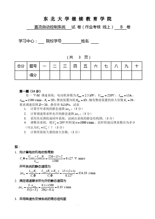
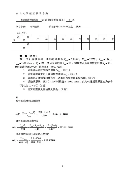
直流自动控制系统 试 卷(作业考核 线上) B 卷
学习中心: 院校学号: 姓 名:
(共 3 页)
解:
1. 先计算电动机电动势常数
220152
Φ0.127 V m i n /r
1500
nom nom a e nom U I R C n --⨯===⋅ 开环系统的静态速降为
()15(21)354.33 r/min 0.127
nom nom a rec op e e I R I R R n C C ∑+⨯+∆====ΦΦ
2. 满足调速要求所允许的静态速降为
第一题(15分)
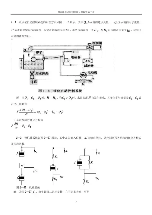
有一V-M 调速系统,电动机参数为nom 2.5 kW P =,nom 220V U =,nom 15A I =,nom 1500 r/min n =,a 2R =Ω;整流装置内阻rec 1R =Ω,触发整流装置的放大倍数s 30K =。
要求调速范围D =20,静差率S ≤10%,试求
1. 计算开环系统的静态速降op n ∆;(3分)
2. 计算调速要求所允许的静态速降cl n ∆;(3分)
3. 采用负反馈组成闭环系统,试画出系统的静态结构图;(3分)
4. 调整该系统,使*
n 20V U =时转速1000 r/min n =,此时转速反馈系数应为多少(可
认为*n n U U ≈)?(3分)
5. 计算所需放大器的放大倍数。
(3分)。
东 北 大 学 继 续 教 育 学 院直流自动控制系统 试 卷(作业考核 线上) B 卷学习中心: 院校学号 姓名(共 3 页)解:1. 先计算电动机电动势常数220152Φ0.127 V min/r 1500nom nom a e nom U I R C n --⨯===⋅ 开环系统的静态速降为 ()15(21)354.33 r/min 0.127nom nom a rec op e e I R I R R n C C ∑+⨯+∆====ΦΦ2. 满足调速要求所允许的静态速降为 ()0.115008.33 r/min 120(10.1)nom cl S n n D S ⋅⨯∆===--3. 采用转速负反馈系统的稳态结构图第一题(15分)有一V -M 调速系统,电动机参数为nom 2.5 kW P =,nom 220V U =,nom 15A I =,nom 1500 r/min n =,a 2R =Ω;整流装置内阻rec 1R =Ω,触发整流装置的放大倍数s 30K =。
要求调速范围D =20,静差率S ≤10%,试求 1. 计算开环系统的静态速降op n ∆;(3分)2. 计算调速要求所允许的静态速降cl n ∆;(3分)3. 采用负反馈组成闭环系统,试画出系统的静态结构图;(3分)4. 调整该系统,使*n20V U =时转速1000 r/min n =,此时转速反馈系数应为多少(可认为*n n U U ≈)?(3分)5. 计算所需放大器的放大倍数。
(3分)4. 当*nU =20V 时,n nom =1000r /min ,则转速反馈系数为*200.02 V min/1000n n nom nom U U rn n α=≈==g5. 闭环系统的放大倍数为 s pop e cl354.331141.548.33α∆==-=-=Φ∆K K n K C n 则所需的放大器放大系数为41.540.1278.79300.02αΦ⨯===⨯e p s KC K K解:1.第二题(20分)某调速系统如下图所示,已知数据为:电动机参数为nom 30kW P =,nom 220V U =,nom 157.8A I =,nom 1000 r/min n =,a 0.1R =Ω;整流装置内阻rec 0.3R =Ω,触发整流装置的放大倍数s 40K =;最大给定电压*nm12V U =,当主电路电流最大时,整定im 45V U =。

交直流电力系统的分析和控制交直流电力系统的分析和控制周孝信目录1.概述2.换流器的工作原理和基本方程式3.两端直流输电系统的控制和稳态运行方式4.交直流混合电力系统的标幺值系统5.交直流电力系统潮流计算6.交直流电力系统稳定计算中直流输电系统的数学模型7.交直流电力系统暂态稳定计算程序及算例8.交直流并列电力系统暂态和动态稳定分析和控制9.交直流并列电力系统的次同步谐振(SSR)分析和控制10.参考文献交直流电力系统的分析和控制周孝信(中国电力科学研究院,北京100085)1 概述自19世纪末三相交流电力问世以来,交流电以其巨大的优越性使其在发电和输配电方面都居于独占地位。
近几十年来,交流电力系统规模越来越大,输电电压越来越高,电网的互联也日趋复杂。
与此同时也产生了一些复杂的技术问题如稳定问题等需要解决。
在这个过程中,人们又回过头来想到能否利用直流输电的优点,在某些特定条件下加以应用,以克服交流输电在技术上的困难,或者取得经济上的更加节省。
首先,直流输电线路的造价比较低。
尽管两端换流站造价较高,但对远距离输电来说,当输电线长度超过某一临界数值时,其总造价将比交流输电低。
又如海底电缆输电,由于直流电通过电缆不需要充电电流,因而可传输更大的功率。
此外,直流输电不存在通常交流输电的稳定问题,在交流系统稳定问题非常突出的情况,采用直流输电是解决稳定问题的有效方案。
直流输电可以联结额定频率不同的电力系统,采用“背靠背”的直流输电环节,可实现不同额定频率交流电力系统之间功率的传输和交换。
直流输电传输功率控制的快速性,提供大功率和小信号快速调制的可能,可用以提供了紧急功率支援,平息交流系统的振荡,提高系统的稳定性。
采用汞弧整流阀技术的第一代直流输电线路在20世纪50年代得到发展。
1954年瑞典建成了110千伏电压约100公里的海底直流输电线(从Gotland到瑞典大陆),输电能力20兆瓦。
60年代可控硅技术的发展,为直流输电提供了价格性能更好的换流元件,使直流输电技术发展到一个新的阶段。
Document Number No of Pages65No of Attached Pages The Three Gorges-Changzhou ± 500 kV DCTransmission Project1JNL100029-886 Rev. 01Prepared Title Reg./Class no.Hans Hillborg, 1999-08-31Approved Resp Dept Hans Tyskhagen, 1999-12-30PKC DC System ProtectionWS-FJ-101D This document is issued by means of a computerized system. The digitally stored original is electronically approved.The approved document has a name and date entered in the approved-field. A manual signature is not required.Summary 1Rewritten Karl-Ola Jonsson 2000-02-09Hans Tyskhagen 2000-03-15Rev ind Revision text Prepared Approved This document describes the DC System Protection for The ThreeGorges-Changzhou ± 500 kV DC Transmission Project. The DC System Protectionincludes the following four groups of protections.• Converter protections.• Pole protections (DC switchyard incl. pole and neutral busses, DC line and DCfilter).• Bipole protections (Bipole neutral and Electrode line).• Converter AC bus and converter transformer protections.For each protective function the purpose of the protection, principle of protectionoperation, fault strategy and protection coordination, consequences of protectionoperation, redundancy or backup of protection and consequences oftelecommunication outage are described.Table of Contents1Introduction (4)2Abbreviation (4)3General Protection Philosophy (5)4Fault Clearing Actions (7)4.1Transfer to Redundant Protection System (7)4.2Retarding of the Converter (8)4.3Order Down to the Rectifier (8)4.4Blocking of the Converter (8)4.4.1Type X - Blocking (9)4.4.2Type Y - Blocking (9)4.4.3Type Z - Blocking (9)4.5AC Circuit Breaker Trip (9)4.6Start Breaker Failure Protection (10)4.7Set Lockout Relay for AC Circuit Breaker (10)4.8Runback (10)4.9Pole Isolation (10)4.10Pole Balancing (10)4.11Reclose Transfer Breaker (10)4.12Close Neutral Bus Ground Switch (11)5Protective Functions (11)5.1Converter Protections (13)5.1.1Valve Short Circuit Protection (14)5.1.2Commutation Failure Prediction (14)5.1.3Commutation Failure Protection (15)5.1.4Voltage Stress Protection (16)5.1.5DC Overvoltage Protection (17)5.1.6Valve Misfire Protection (18)5.1.7Thyristor Monitoring (18)5.1.8DC Overcurrent Protection (19)5.1.9Back-up DC Overcurrent Protection (20)5.1.10High Angle Supervision (21)5.1.11Valve DC Differential Protection (22)5.1.12Auxiliary Power Supervision (23)5.1.13Valve Cooling System Protection (23)5.2Pole Protections (24)5.2.1DC Harmonic Protection (25)5.2.2DC Pole Bus Differential Protection (25)5.2.3DC Neutral Bus Differential Protection (26)5.2.4DC Pole Differential Protection (27)5.2.5Electrode Line Open Circuit Protection (27)5.2.6DC Filter Overload Protection (28)5.2.7DC Filter Capacitor Unbalance Protection (29)5.2.8DC Filter Differential Protection (29)5.2.9DC Line Protections (30)5.2.10DC Undervoltage Protection (34)5.2.11Open Line Test Operation (35)5.2.12Open Line Test Supervision (35)5.2.13Reverse Power Direction Protection (35)5.2.14Smoothing Reactor Protective Relays (36)5.3Bipole Protections (41)5.3.1Bipole Neutral Bus Differential Protection (42)5.3.2Station Ground Overcurrent Protection (42)5.3.3Transfer Breaker Protections (43)5.3.4Metallic Return Transverse Differential Protection (47)5.3.5Metallic Return Longitudinal Differential Protection (47)5.3.6Metallic Return Conductor Ground Fault Protection (48)5.3.7Electrode Line Overload Protection (48)5.3.8Electrode Line Impedance Supervision (49)5.3.9Electrode Line Unbalance Supervision (49)5.4Converter AC Bus and Converter Transformer Protections50 5.4.1Converter AC Bus Differential Protection (51)5.4.2Converter AC Bus and Converter TransformerOvercurrent Protection (51)5.4.3Converter AC Bus and Converter Transformer DifferentialProtection (52)5.4.4Converter Transformer Differential Protection (52)5.4.5Converter Transformer Overcurrent Protection (53)5.4.6Converter Transformer Thermal Overload Protection (54)5.4.7Converter Transformer Winding Differential Protection (54)5.4.8Converter AC Bus Overvoltage Protection (56)5.4.9Converter Transformer Neutral Shift Protection (56)5.4.10Converter Transformer Zero Sequence Current Protection.57 5.4.11Converter Transformer Overexcitation Protection (58)5.4.12Converter Transformer Saturation Protection (58)5.4.13Last Breaker Protection, Zhengping only (59)5.4.14Converter Transformer Restricted Earth Fault Protection (59)5.4.15Converter Transformer Protective Relays (60)6References (65)1 IntroductionThis document describes the DC protections functions according to therequirements in [1]. For all protections the following items are described in detail.•Purpose of the protection.•Principle of protection operation.•Fault strategy and coordination between the DC control, DC protection and theAC protection.•Consequences of protection operation, such as DC control and switching actioninitiated at both converter stations.•Redundancy of protection or reference to what protection acts as back up.•Consequences of telecommunication outage.The following information is found in separate reports•Required accurancy of measuring signals is presented in [4]•Detailed calculations of the protection settings together with limiting faultscases and/or criteria that determines these settings is presented in [5] and [8].2 AbbreviationACP AC Control and Protection.CT Current Transformer.DCCT DC Current Transformer.GRTS Ground Return Transfer Switch.HAS High Angle Supervision.IVD Three phased rectified AC currents ∆-winding.IVY Three phased rectified AC currents Y-winding.MACH 2Modular Advanced Control for HVDC and SVC.MC Main ComputerMRTB Metallic Return Transfer Breaker.NBGS Neutral Bus Ground Switch.NBS Neutral Bus Switch.OCT Optical Current Transformer.OLT Open Line Test3 General Protection PhilosophyThe purpose of the HVDC System Protection is to cause the prompt removal of anyelement of the transmission system from service, e.g. when it suffers a short circuitfault or when it starts to operate in any abnormal manner that might cause damageor otherwise interfere with the effective operation of the rest of the system. Theprotective system is aided in this task by the AC circuit breakers, which are capableof de-energizing the converter transformers, thereby eliminating the direct currentand voltage.The latest protection system uses powerful computers and allows future adoptionof new protective functions and adjustments of existing protections in a flexiblemanner. The protection system is built in a modular way, which enables astructured design for complete system.Redundant Control and Protection systems (Main 1 and Main 2) are provided.The HVDC control and protection systems are based on a fully redundant activestandby concept. In general, each system consists of primary and backupprotections.Figure 1 System overview.Each of the two main systems consists of two main computers MC1 and MC2.MC1 contains the DC control and DC protections set 1 and MC2 contains DCProtections set 2.In order to improve security for converter, pole and bipole protections which canoperate inadvertently for control system faults measurements, the concept of usingfast changeover from active to standby system is adopted. Before a trip order isissued from active protection system, a system change over is performed wheneverdelay due to such changeover is acceptable. If the redundant system issues a triporder as well, the order will be sent through. To separate between change over anda block/trip orders, both time and level separation is used.The converter AC bus and the converter transformer protections are active in bothMain 1 and Main 2 protection systems.In addition, each system has extensive self-supervision which further enhancessystem security. Any detected failures in the control and protection hardware willSYSTEM OVERVIEW MAIN 1( CUBICLE A )DC SYSTEMPROTECTIONSET 2CONTROLDC SYSTEMPROTECTIONSET 1MC 1MC 2MAIN 2( CUBICLE B )DC SYSTEM PROTECTION SET 2CONTROL DC SYSTEM PROTECTION SET 1MC 1MC 2result in a request for change over, which will be executed if there is a stand-by system that is ready to take over.The proposed protective scheme is designed to meet the following general requirements:a)Fault conditions or other abnormal conditions that might expose equipment tohazards shall be detected. Also conditions that cause unacceptable disturbances to operation should be detected and the faulty or overstressed equipment should be taken out of service or relieved of stresses in a controlled way.b)The aim of the protection design is to detect every condition, according toabove, with at least two protections.c)Steps to minimize the possibility of fault in one converter causing protectiveaction in other converters shall be taken.d)The protections will be arranged into overlapping protective zones. For eachfault case, there should be a fast main protection with a limited protective zone.The main protection is normally supported with a slower or less sensitivebackup protection. The backup protection will, if possible, be based on adifferent measuring principle and, when applicable, with a more extendedprotective zone.e)The consequences of protection operating and protection coordination shall bearranged to avoid bipole outages.f)Auxiliary power supplies and sources to main 1 and main 2 protections shall beseparated.g)Tripping paths to the breaker shall be redundant. Trip coil on the breaker shallbe redundant and fed by two different auxiliary power supplies.h)The protections shall be arranged so that testing and maintenance can be carriedout without affecting the operation of the converter.Bipole protection philosophy:The aim with the overall protection philosophy is to avoid undue bipole outage during any circumstances.Examples of possible faults and disturbances which are covered by the proposed protection philosophy:−Common mode disturbances and faults, such as AC system disturbances which will give disturbances to both poles.−DC side disturbances related to common bipole equipment, such as the bipole neutral bus, station earth, metallic return, electrode line, transfer breakers etc.−Domino effect, such as faults in one converter causing protective action in other converter.According to above philosophy:a)Protections related to equipment within a pole are separated between the poles,and have separate measuring devices.b)Bipolar protections are used for equipment common for the two poles. Eachpole has its own set of bipole protections using separated measuring paths.c)No protection, pole related or bipole related is allowed to trip the other pole.d)There are no single protection actions for bipole related faults or disturbanceswhich can lead to a bipole outage.It is recognized that during bipolar operation mode with temporary groundconnected, a fault in one of the two converter poles shall lead to a shutdown ofthe other pole too. This is done in order to avoid current in the station groundnet.4 Fault Clearing ActionsThe switching actions that are utilized to clear DC faults and DC breaker/switchfailures are:a)Transfer to redundant control and protection system.b)Retard and blocking of the converters.c)Order down of the converter.d)Tripping of AC circuit breaker.e)Start breaker failure protection.f)Set lockout relay for AC circuit breaker.g)Runback.h)Pole isolation.i)Pole balancing.j)Reclose transfer breaker.k)Close neutral bus ground switch.These switching actions are explained below.4.1 Transfer to Redundant Protection SystemA protection action may be the result of an error in some part of the active controlsystem, such as a measurement failure, i.e. an overcurrent or overvoltage situationmay depend on a failure in the control system. To avoid unnecessary trips atcontrol failures, some protections will order a change over to the other Control andProtection system as the first action. This protective action is used when oneprotection system is active and the other is in stand-by, except when instantaneousfault clearing is required.If a control failure was the reason for the protection action, the trip condition willdisappear since the whole control is changed to a healthy system.At the same time when the change over is executed, the other system will becomeactive. The system that initiated the change over will be set in a not Stand-bycondition which means that it is not possible to automatically order this system tobe in active mode again. A manual action must be taken to put the system back inStand-by mode. If a system is in service with no alarm but not set in Stand-bymode, an alarm will be given to the operator.The protection system that is in Stand-by mode is continuously supervised. Adetected failure will set the system in not Stand-by mode, thus preventing a changeover to this system.4.2 Retarding of the ConverterRetarding means that as soon as it has been ordered, the next control pulses aredelayed with respect to the previous one. This increases the firing angle until thefull inverter operation that constitutes the limit for the firing angles has beenachieved.The retarding will reverse the polarity of the rectifier converter voltage, therebyextinguishing the direct current.4.3 Order Down to the RectifierAn order down means retarding of the converter and after the retard that the firingangle be kept at minimum extinction angle until the ORDER DOWN is released.When the order down is released, the converter firing angles are decreased untilnormal operation is reached. This protective action is used to clear line faults withminimum disturbances on the transmission.Order Down includes a preset number of restart attempts.4.4 Blocking of the ConverterBlocking means removing the control pulses from the thyristors. When this is done,the valves will stop conducting as soon as the current reaches zero.When blocking, it is sometimes desirable to provide a current path for the DC sidecurrent. If so, the bypass pairs (two opposite valves within the same six-pulsegroup connected to the same AC phase) are simultaneously fired. This provides aby pass across the converter and is normally employed when permanent earth faultsare detected.Figure 6 Bypass pair firing.The protective blocking actions can be categorized as X, Y, or Z type blocking. AnX-blocking always implies a blocking without simultaneous firing of by-pass pairsand as well a blocking with BPP when the AC breaker has opened in the inverter.A Z-blocking always implies a blocking with simultaneous firing of by-pass pairs.A Y-blocking is conditional and implies blocking without by-pass pairs in therectifier and with by-pass pairs in the inverter. All converter blocking orders areredundant and have redundant signal paths to the converter blocking sequences.4.4.1 Type X - BlockingA category X-blocking is used during valve faults and it is mainly ordered byprotections which are initiated for a short circuit across a valve. X-blocking willalso be used for faults in the firing circuits where a correct selection of by passpairs cannot be achieved.In rectifier operation, a valve short circuit gives rise to an initial large short circuitcurrent through a healthy valve in the three pulse valve group accommodating theshort circuited valve. To limit the overcurrent to one pulse only, the fault detectionmust be fast and the converter must be blocked without firing of by-pass pair.In inverter operation, a valve short circuit does not give rise to a large initial shortcircuit current. Therefore, it is not necessary to immediately block the converter. Inorder to limit the amplitudes of the short circuit currents, the converter is retarded,i.e. kept at minimum commutation margin angle until the converter is blocked.The complete X-blocking fault clearing sequence may be summarized as follows:Rectifier:−Immediate retarding of the converter.−Subsequent blocking of the converter without firing of by-pass pairs.−Tripping of AC circuit breakers feeding the converter.Inverter:−Immediate retarding of the converter.−Tripping of AC circuit breaker.−Blocking of the converter with by-pass pair when the AC breaker has started toopen.4.4.2 Type Y - BlockingThe Y-blocking is generally used for DC side faults which do not expose theequipment to serious stresses, AC faults and manual blocking of the pole.−Immediate retarding of the converter.−The converter is blocked directly with by-pass pairs in the inverter andtherefore resembles a category Z blocking. In the rectifier, the order to block isdelayed to bring about the extinction of the current before blocking. Theblocking is made without by-pass pairs in the rectifier if the DC current isbelow a voltage dependent limit. Otherwise, the converter is blocked with by-pass pairs.4.4.3 Type Z - BlockingThe Z-blocking is generally used for earth faults or overcurrents related to the DCside.Z-blocking always implies immediately retarding of the converter and blockingwith simultaneous firing of by-pass pairs.4.5 AC Circuit Breaker TripThe AC circuit breaker trip disconnects the AC side of the converter transformersfrom the AC power source. By doing this, the AC system (which is primarily aconstant voltage source) is prevented from feeding a fault on the valve side of theconverter transformer. Also, the removal of AC voltages from the valves avoidsunnecessary voltage stresses especially when the valves have performed severecurrent stresses.All protective trip orders to the AC circuit breakers will energize both trip coils inthe breakers through two different trip devices. The redundant trip orders will alsobe fed by two redundant auxiliary power supplies.This action is generally activated by a serious fault in the converter pole.4.6 Start Breaker Failure ProtectionAt the same time a trip order is sent to the AC breaker, generally an order is alsosent to start the breaker failure protection. If the breaker does not succeed inopening, the breaker failure protection orders a trip of the next breaker further out.4.7 Set Lockout Relay for AC Circuit BreakerIf a protection trip order has been sent to the AC breaker, then an order to thelockout relay will also be sent to prevent the breaker from being closed before theoperator has checked the cause of the trip. The lockout relay circuit is manuallyreset by operator.4.8 RunbackThe runback feature will, as quickly as possible, reduce the transmitted power to apreset maximum level in an attempt to keep the transmission in operation.This action is generally activated by overload conditions in the valve or in theelectrode line.4.9 Pole IsolationThe isolate pole sequence implies disconnecting the DC bus from the DC line anddisconnecting the converter neutral from the electrode line.This is done either manually during normal shut down or from protective actionsfor faults which trip the pole.4.10 Pole BalancingCurrent balance between the poles is achieved in normal operating mode. Shouldhowever the transmission be running in another operation mode initiated by theoperator, high electrode line current may occur. Current balancing can be achieved,initiated manually or from protection action. The pole balancing order is treated asa runback. The runback level in each pole, will be decided out from the lowestcurrent order, of the two poles.This action is generally activated by a measured current in the electrode line duringbipolar operation.4.11 Reclose Transfer BreakerThe transfer breaker reclose sequence is initiated from i.e. neutral bus switchfailure protection, to protect the pole equipment and station ground net in case theneutral bus switch fails to commutate the current over to the electrode line.4.12 Close Neutral Bus Ground SwitchThe neutral bus ground switch close sequence is initiated from i.e. electrode lineopen circuit protection, to reduce possible high neutral voltages.5 Protective FunctionsThis section describes the Main1 DC protections used for the ThreeGorges-Changzhou ± 500 kV DC Transmission Project. Main 2 protection setup isidentical to the Main 1 but with redundant measuring points.The following four main groups of protections are included.a)Converter protections containing:Set 1 S et 2Valve short circuit protection Valve short circuit protectionCommutation failure prediction Commutation failure protectionCommutation failure protection DC overvoltage protectionVoltage stress protection Back-up DC overcurrent protectionValve misfire protection Valve DC differential protectionThyristor monitoringDC overcurrent protectionHigh angle supervisionb)Pole protections containing:Set 1 S et 2DC pole bus differential protection DC harmonic protectionDC pole differential protection DC neutral bus differential protectionElectrode line open circuit protection Electrode line open circuit protectionDC filter capacitor unbalance prot. DC filter overload protectionDC filter differential protection DC undervoltage protectionDC line protection (travelling wave) Reverse power direction protectionDC line protection (derivative andlevel)DC line longitudinal differential prot.Open line test supervisionc)Bipole protections containing:Set 1 S et 2Bipole neutral bus differential prot.Station ground overcurrent protection Transfer breaker protections (NBGS,Back-up transfer breaker protectionsNBS, GRTS, MRTB)(NBGS, NBS, GRTS, MRTB)Metallic return longitudinal diff. prot.Metallic return transverse differential prot. Electrode line overload protection Metallic return conductor ground faultprotectionElectrode line unbalance supervisiond)Converter AC bus and converter transformer protections containing:−Converter AC bus differential protection.−Converter AC bus and converter transformer overcurrent protection.−Converter AC bus and converter transformer differential protection.−Converter transformer differential protection.−Converter transformer overcurrent protection.−Converter transformer thermal overload protection.−Converter transformer winding differential protection.−Converter AC bus overvoltage protection.−Converter transformer neutral shift protection.−Converter transformer zero sequence current protection.−Converter transformer overexcitation protection.−Converter transformer saturation protection.−Converter transformer restricted earth fault protection.In addition to the above four groups the following protections are also included, which are physically located in other distributed systems:−Auxiliary power supervision−Valve cooling system protection−Smoothing reactor protective relays−Electrode line impedance supervision−Converter transformer protective relays−Last breaker protection, Zhengping only.5.1 Converter ProtectionsIn general the converter protection measuring location and set up in each mainprotection system is as presented in the figure belowFigure 2 Configuration of the converter protectionsM A I N 1 C O N V E R T E R P R O T E C T I O N , S E T 1M A I N 1 C O N V E R T E R P R O T E C T I O N , S E T 25.1.1 Valve Short Circuit ProtectionPurpose of the protectionTo protect the thyristor valve from stresses due to short circuits on the DC-side of the converter transformer.Principle of protection operationThe protective function uses the converter transformer currents IVY and IVD, the DC pole bus and neutral bus direct currents and the DC filter current. In normal operation the currents are balanced.Higher amplitudes in the converter transformer currents than in the direct current is a criterion on a valve short circuit or other phase to phase short circuits. At an excess in AC side current, the converter is tripped instantaneously.Fault strategy and protection coordinationWhen a valve short circuit occurs, the high amplitude current is conducted by the faulty valve and by a second healthy valve as it attempts to commutate. If a third valve is fired in the same three pulse group, such a high current will also be conducted by this valve. This is avoided by a fast detection of the fault and by ordering a blocking without by-pass pairs before the third valve is fired. Consequences of protection operation−X-block of the converter.−Trip of the AC circuit breaker.−Pole isolation order.−Start of the breaker failure protection.−Set lockout of AC circuit breaker.Redundant and backup of protectionThe valve short circuit protection in the other set.Consequences of telecommunication outageNot applicable.5.1.2 Commutation Failure PredictionPurpose of the protectionTo reduce the number of commutation failures caused by AC net disturbances. Principle of protection operation7KH SURWHFWLYH IXQFWLRQ XVHV WKH ]HUR VHTXHQFH FRPSRQHQW DQG WKH FRPSRQHQWVof the AC voltage.At an abnormal AC voltage the function will instantaneously order an increase of the commutation margin in order to avoid commutation failure.Fault strategy and protection coordinationNot applicable.Consequences of protection operationIncrease of the inverter firing angleRedundant and backup of protectionCommutation failure protections.Consequences of telecommunication outageNot applicable.5.1.3 Commutation Failure ProtectionPurpose of the protectionTo detect commutation failures in the twelve-pulse converter that are caused from AC net disturbances or other abnormal commutation conditions.Principle of protection operationThe protective function uses the converter transformer currents IVY and IVD, the DC pole bus and neutral bus direct currents and the DC filter current. Commutation failures in a six-pulse bridge are characterized by a significant reduction of AC phase current amplitudes whereas the current on the DC side is subject to an increase. This condition is detected. A commutation failure is not a fault as such but an indication of other faults such as control pulse transmission faults or AC network faults.Persistent fault in one of the six-pulse bridges are most likely a result of valve misfire (e.g. no control pulse or continuos control pulse to a valve) whereas intermittent faults in both bridges will occur at AC network disturbances. These facts are used to distinguish between control pulse transmission fault and AC system faults.At a commutation failure the protection will instantaneously order an increase of the commutation margin in the faulty converter to improve recovery.At persistent commutation failures in one of the six-pulse bridges, the protection will trip the converter after a preset time delay. At persistent commutation failures in both six-pulse bridges, the protection will trip the converter after another preset time delay.Fault strategy and protection coordinationThe part that detects commutation failures in both six-pulse bridges, i.e. due to AC side disturbances must be coordinated with the longest clearing time for AC faults. Consequences of protection operationAt all commutation failures:−Instantaneous advancing of firing angle in faulty converter to improve recovery.−Lock order to the line protections in the rectifier station via telecom to avoid line protection operation.−Start of the Transient Fault Recorder.After 2 commutation failures, within a defined time window:−Transfer order to redundant Pole Control.After 3 commutation failures, within a defined time window (Control pulse transmission fault):。
国家电网公司直流换流站运维技能培训系列教材国家电网公司防止直流换流站单、双极强迫停运二十一项反事故措施国家电网公司运维检修部组编《国家电网公司防止直流换流站单、双极强迫停运二十一项反事故措施》批准:帅军庆审定:李庆林复审:张启平刘泽洪梁旭明初审:叶廷路高理迎王玉玲娄殿强编制:冀肖彤孙杨张民王庆石岩唐开平佘振球前言目前,公司系统已投运跨区直流输电工程13个,换流站23座,输送容量3352.4万千瓦。
“十二五”期间,公司还将有一大批跨区直流输电工程开工建设并投运。
跨区直流输电系统作为国家电网主网架的重要组成部分,是在更大范围内实施电力资源优化配置的重要战略通道,具有输送容量大、输电距离长、技术先进、设备复杂的特点,对设备运维提出了更高要求。
直流输电在我国起步时间晚,发展速度快,运维人才相对缺乏。
为了进一步提高培训工作的系统性和针对性,加快人才培养速度,国家电网公司运维检修部组织运维单位、设备厂家、科研院所编写了本套教材。
本套教材的内容来源于设备厂家说明书、现场运行规定及实际运维经验总结,涵盖了直流运行、控制保护、换流阀及阀冷却专业的运行维护技术,特别对现场作业技能进行了详细的描述,编写力求准确、清晰,面向生产一线,突出现场实用性。
本套系列教材目前包括《国家电网公司防止直流换流站单、双极强迫停运二十一项反事故措施》、《国家电网公司直流换流站设备状态检修管理标准及工作标准》、《直流输电原理》、《设备运行》、《系统运行》、《MACH2控制保护系统》、《SIMADYN D控制保护系统》、《ABB技术换流阀》、《SIEMENS 光触发技术换流阀》、《AREVA技术换流阀》、《Sweden Water技术阀冷却系统》、《高澜技术阀冷却系统》、《许继技术阀冷却系统》、《典型故障汇编》共十四个分册,后续将逐步修编完善。
由于编写时间仓促,疏漏之处在所难免,恳请广大读者批评指正。
2012年7月目录1.防止非电量保护误动 (1)2.防止直流保护和换流变电气量保护误动 (2)3.防止内冷水保护误动 (3)4.防止最后断路器保护误动 (4)5.防止直流控制系统故障 (5)6.防止换流阀及阀控系统故障 (6)7.防止电压、电流回路故障 (7)8.防止控制保护软件错误 (8)9.防止站用交流电源故障 (9)10.防止站用直流电源故障 (10)11.防止内冷水主泵故障 (11)12.防止跳闸回路常闭接点故障 (12)13.防止直流开关、刀闸辅助接点异常变位故障 (12)14.防止网络通讯故障 (13)15.防止阀厅损坏故障 (14)16.防止误操作事故 (15)17.防止交、直流滤波器及并联电容器故障 (16)18.防止换流站室外端子箱、接线盒受潮故障 (17)19.防止换流站室外设备污闪故障 (17)20.防止CT选型不当 (18)21.防止主变与换流变共串 (18)1.防止非电量保护误动1.1在设备采购阶段,应在各类设备规范书中明确要求作用于跳闸的非电量元件都应设置三副独立的跳闸接点,按照“三取二”原则出口,三个开入回路要独立,不允许多副跳闸接点并联上送,三取二出口判断逻辑装置及其电源应冗余配置。
东 北 大 学 继 续 教 育 学 院直流自动控制系统 试 卷(作业考核 线上) B 卷学习中心: 忻州奥鹏 院校学号:T030163姓名 薄涛解:先计算电动机电动势常数 220152Φ0.127 V min/r 1500nom nom a e nom U I R C n --⨯===⋅开环系统的静态速降为()15(21)354.33 r/min 0.127nom nom a rec op e e I R I R R n C C ∑+⨯+∆====ΦΦ 满足调速要求所允许的静态速降为()0.115008.33 r/min 120(10.1)nom cl S n n D S ⋅⨯∆===--第一题(15分)有一V-M 调速系统,电动机参数为nom 2.5 kW P =,nom 220V U =,nom 15A I =,nom1500 r/min n =,a 2R =Ω;整流装置内阻rec 1R =Ω,触发整流装置的放大倍数s 30K =。
要求调速范围D =20,静差率S 10%,试求1. 计算开环系统的静态速降op n ∆;(3分)2. 计算调速要求所允许的静态速降cl n ∆;(3分)3. 采用负反馈组成闭环系统,试画出系统的静态结构图;(3分)4. 调整该系统,使*n20V U =时转速1000 r/min n =,此时转速反馈系数应为多少(可认为*n n U U ≈)(3分) 5. 计算所需放大器的放大倍数。
(3分)采用转速负反馈系统的稳态结构图1.第二题(20分)某调速系统如下图所示,已知数据为:电动机参数为nom 30kW P =,nom 220V U =,nom157.8A I =,nom 1000 r/min n =,a 0.1R =Ω;整流装置内阻rec 0.3R =Ω,触发整流装置的放大倍数s 40K =;最大给定电压*nm12V U =,当主电路电流最大时,整定im 45V U =。
(此文档为word格式,下载后您可任意编辑修改!) 毕业设计(论文)题目背靠背变换器的仿真研究专业电气工程及其自动化背靠背变换器的仿真研究摘要背靠背电压源型变换器在轻型直流输电系统,变速恒频风力发电系统轻型直流输电系统以及电动机变频调速中有着越来越重要的作用。
PWM 整流-PWM逆变形式的背靠背VSC不仅具有良好的输出性能,更具有良好的输入性能,可获得任意功率因数的正弦输入电流,且具有能量双向流动的良好能力。
介绍了背靠背电压源型变流器在dq同步旋转坐标系下的动态数学模型、背靠背电压源型变流器与两端交流系统互联时的功率交换控制原理。
设计了基于直接电流控制的双闭环控制器,实现了有功功率和无功功率的解耦控制,基于系统传递函数,采用极点配置的PI参数设计方法,使控制器的期望性能指标与PI参数之间建立了直接的量化关系。
最后,利用PSCAD软件搭建了背靠背VSC变换器控制仿真模型,最终通过对背靠背VSC与两端交流系统的功率交换进行控制仿真,验证了所设计控制器的有效性。
关键词:背靠背电压源型变换器、dq轴解耦控制、直接电流控制AbstractBack-to-back voltage source converter is becoming more and more important in new fields such as VSCF wind power generator system and HVDC light. back-to-back VSC in the form of PWM rectifier-PWM inverter not only has good output performance, but also has good input performance,and it can obtain sinusoidal input current with any power factor as well as a bidirectional energy flow.The dynamic mathematical model for back-to-back VSC under dq synchronous reference frame is represented as well as the power exchange control principle between converters and two side ac systems.t A dual closed loop controller based on direct current control strategy is designed for active power and reactive power exchange between the converter and two side ac systems, active power control and reactive power control are decoupled. According to the system transfer function, the direct quantitative relationship is established between the desired performance targets and PI parameters based on pole-assignment for PI parameter′s design metho d.Finally, power exchange control simulation model for back-to-back VSC based on PSCAD is set up, Power exchange control between back-to-back VSC and two side ac systems is simulated, the validity of the proposed controller is demonstrated by the simulation results.Keywords:back-to-back voltage source converter, dq axis decoupled control, direct current control目录第1章绪论 (1)1.1 选题背景及意义 (1)1.2 背靠背VSC的研究现状 (1)1.2.1 背靠背VSC的应用情况 (1)1.2.2 VSC控制策略的研究现状 (5)第2章背靠背VSC的数学模型 (6)2.1 背靠背VSC的工作原理 (6)2.2 背靠背VSC的数学模型 (10)第3章背靠背VSC的控制器设计 (11)3.1 背靠背VSC的上层控制策略 (11)3.2 背靠背VSC的控制器设计 (12)3.2.1 背靠背VSC内环电流控制器设计 (12)3.2.2 背靠背VSC直流电压控制器设计 (15)3.2.3 背靠背VSC2侧控制器设计 (18)3.3 本章小结 (20)第4章背靠背VSC仿真运行结果 (22)4.1 背靠背VSC 系统功率控制仿真建模 (22)4.1.1 锁相环 (22)4.1.2 dq变换模块 (23)4.1.3 调制波发生模块 (23)4.1.4 上层控制模块 (24)4.1.4 PWM发生模块 (25)4.2 背靠背VSC 系统功率控制仿真结果 (28)4.2.1 直流电压控制仿真结果 (28)4.2.2 VSC1侧无功功率控制仿真结果 (28)4.2.3 VSC2侧有功功率控制仿真结果 (30)4.2.4 VSC2侧无功功率控制仿真结果 (31)结论 (33)致谢 (22)参考文献 (32)附录 (42)第1章绪论1.1 选题的背景及意义目前,以全控型器件和PWM 技术为特征的背靠背电压源型变流器(VoltageSource Converter, VSC),由于具有能够实现能量的双向流动、有功功率和无功功率可独立控制、产生的谐波含量小、直流电压可控等诸多优点,在节能与新能源备受重视的当今社会,已成为变速恒频风力发电系统、轻型直流输电系统及电动机变频调速技术的核心,从而得到了广泛的关注[1~5]。
电气工程与自动化"Dianqi Gongcheng yu Zidonghua一种站用直流系统异常并列检测的方法刘新敏郭%&奇林邱舒峰杨冲(广东电网公司梅州供电局,广东梅州514021)摘要:直流系统异常并列是直流系统的常见故障。
现简要介绍了直流系统异常并列的危害及常用查找手段,阐述了切换桥模型原理,分析了通过切换桥检测站用直流系统异常并列的方法。
关键词:直流系统;异常并列;检测方法;切换桥0引言厂站直流系统是站内重要设备,厂站配置有两套直流系统,并且两套直流系统不可长期并列运行。
两套直流系统长期并列运行将损坏电电,且去配合,进而扩大停电围,不厂站的运行。
运行过,两套直流系统经常会因为运行人员操作错误或接线错误导致异常并列的情况出现。
1直流系统异常并列的常用查找手段的直流系统,配备的直流系统异常并列检测I设备,异常并列的现有两是套直流系统现异常,另一套直流系统也同时报绝缘异常,运通过绝缘电站用直流系统是异常并列行;二是运.套直流系统电的电,套系统电,现异常并列I方法法在无接地故障时作出两套系统异常并列的,而设备长异常并列运行,损坏设备;方法只期查是异常并列,不及现异常并列情况。
2切换桥模型分析直流系统对于系统的接地检测主要利用了平衡桥原理,电大°桥原理,了不桥切换桥,了通过切换桥检测直流系统异常并列的方法°2.1切换桥模型组成切换桥模型1示,该模型包括了电R1、二电阻!%、第三电阻!&和第四电阻和的,直流系统桥电的10倍。
该模型还包括开关"1、开"%、三开关"&四开K',R i、R%分别通过K i、K%至直流母的正极,端;!&、!'分别通过K&、"'至直流母的负极,端接地°2.2切换桥的控制以1s为基本单位,8s为一个周期。
其中,K i在第1s闭合,第4s断开;K%2s闭合,3s断开;K&5s闭合,第8s断开;K'6s闭合,7s开。
单片机控制的全数字式直流调速系统
候媛彬
【期刊名称】《工矿自动化》
【年(卷),期】1990(000)002
【摘要】本文介绍了以MCS-51单片机为核心,对直流双闭环调速系统实现全数字化控制的方法。
重点阐述了系统的硬件设计,程序编制及提高控制精度和抗干扰的措施,其数学分析结果,数字仿真结果和全数字化后系统实验测试结果基本吻合。
【总页数】4页(P18-21)
【作者】候媛彬
【作者单位】西安矿业学院电气工程系
【正文语种】中文
【中图分类】TP1
【相关文献】
1.基于单片机控制的直流电机PWM调速系统设计 [J], 李玮
2.基于单片机控制的PWM直流调速系统的研究 [J], 张永志
3.单片机控制的直流电机闭环调速系统设计 [J], 詹庄春
4.利用单片机控制直流电机调速系统设计 [J], 王山卉
5.基于单片机控制的PWM直流电机调速系统 [J], 尹冬梅
因版权原因,仅展示原文概要,查看原文内容请购买。
解析电力系统及其自动化应用谭士滨发布时间:2021-09-23T03:37:48.285Z 来源:《建筑学研究前沿》2021年13期作者:谭士滨1 李小莉2[导读] 随着国家综合国力的不断增强,人民的生活水平不断地提高,人们对电能的需求越来越高。
1身份证号码:4331271xxxx7063613;2身份证号码:46000319xxxx207223摘要:随着国家综合国力的不断增强,人民的生活水平不断地提高,人们对电能的需求越来越高。
电力系统的功能也在不断地提高,安全性和可靠性逐步得以增强,并且电力管理部门根据实际情况,加强相关电力系统及其自动化的应用,优化内部管理结构,降低功率损耗,提高电能质量,为国家创造更多的经济收益,同时满足当前人民对电能的需求。
关键词:电力系统;自动化;应用;前言:电力是当前现代化社会各行各业维持正常工作生产及保障日常生活的重要能源,保障了社会电力供给,对电力系统的完善和重视,于电力事业的发展具有相当重要的意义。
在日常生活中使用的电力设备是由电能的产生,输送,分配及使用同时进行的,电力系统则是将产生电能的设备完成期间的转换、输送,必要时需要进行测量和电能的保护,是电能相关系统组成的整体,称之为电力系统。
在电力系统的相关控制过程中,通过适当的应用自动化技术,可以更好提高系统运行的效率,减小人工和物力资源的损耗,同时将传统的手工操作转化为新型的机械化操作,进而更有利于满足当前社会快速发展的需求。
一、电力系统及其自动化的特点1、避免人为因素电力系统自动化,主要包括互联网信息技术的应用,计算机信息技术的应用,电子管理的各个不同部分,这些组成部分可以增加国内电力系统整体的电力供电量,从而实现电网的规模不断扩大。
同相关能量之间的转换,在日常生活中十分的便捷,便于远距离的输送和控制,所以相关的技术及其应用在整个国民经济运行过程中起着积极的影响作用。
例如,在当前互联网快速发展的今天,人们如果长期处于一个没有电能的环境中,就没有办法适应,甚至难以生存。