海康威视DS1003键盘说明书资料
- 格式:pdf
- 大小:1011.22 KB
- 文档页数:10

DVR键盘使用说明使用前请仔细阅读使用说明目录一、性能介绍1、概述2、性能指标二、主要功能介绍三、键盘面板介绍1、正面面板2、后面面板3、侧面面板四、键盘的操作使用1、云台镜头控制2、设置波特率3、画面分割选择五、安装连接一、性能介绍:1、概述DVR控制键盘是配合DVR主机、嵌入式硬盘录像机等前端设备来控制高速智能球机、解码器、恒速球机等终端接收器配套的产品。
控制键盘与接收器之间采用EIA/RS -485电气接口,在不加总线驱动的情况下,一台键盘最多可控制128台球机或解码器等终端设备,键盘与接收器的最大通信距离达1.5Km。
利用控制键盘可方便地对高速球型摄像机等终端设备进行控制。
2、性能指标a、电气指标供电电源:DC9V 500mA随机配电源适配器:AC220V±10% 50/60HZ转DC9V 500mA通讯连接方式:与主机连接采用RS-232(单路)和RS-485通讯。
与控制设备采用RS-485总线控制方式,波特率为1200bps、2400bps、4800bps、9600bps、19200bpsS可调。
b、机械指标尺寸:70(高)X 165(宽)X 270(长)mmC、环境指标温度:0℃~60℃湿度:90%RH二主要功能介绍:DVR控制键盘具有下列主要功能:1.键盘输出采用光电隔离485控制,抗干扰性强,传输距离远。
2.设定球形摄像机或解码器的地址范围:1~128。
3.可对高速球的内置云台进行变速操作。
4.可对高速球进行预置点的设置和调用。
5.可对高速球进行手动或自动控制。
6.手动控制摄像机的变倍﹑变焦﹑光圈。
7.可控制多台球形摄像机和解码器等终端设备。
8.可实现与单台或多台(4台)DVR主机或嵌入式硬盘录像机联控。
三、键盘面板介绍:1、正面面板控制键盘正面面板上有变速控制摇杆,按键和LED数码管显示。
显示屏用于显示系统状态及操作信息。
摇杆控制云台上、下、左、右作变速运动及手动定点。
DS100用户手册版本:V2.0固件版本:Ver 6.4.1(build 52)日期:2012年2月内容介绍本文档主要介绍了DS100双指纹头考勤设备的用户界面及功能菜单的操作。
关于本手册本手册中★号标示的功能并非所有设备具备。
请以实际产品为准。
本文档中的图片说明,可能与您手中产品的图片不符,请以实际产品显示为准。
DS100用户手册目录1.使用须知 (1)1.1推荐使用步骤 (1)1.2按压指纹的方式 (2)1.3关于考勤 (3)1.3.1 考勤状态选择 (3)1.3.2 员工考勤方式 (4)1.4设备通讯 (9)1.5主菜单 (10)2.用户管理 (12)2.1 新增用户 (12)2.2 管理用户 (15)2.2.1 查找用户 (16)2.2.2记录查询 (17)2.2.3 编辑用户 (18)2.2.4 删除用户 (19)2.2.5 新增用户 (20)2.3 短消息 (20)2.3.1 设置短消息 (21)2.3.2 员工查看短消息 (22)2.4 卡管理 ★ (24)2.4.1 登记号码卡 (24)2.4.2 清空卡信息 (25)2.4.3 复制卡信息 (26)2.4.4卡参数设置 (26)3.通讯设置 (28)目录3.1 网络设置 (28)3.2 连接设置 (29)3.3 无线设置(WIFI) ★ (30)3.4 无线网络(GPRS) ★ (32)4.系统设置 (34)4.1 系统参数 (34)4.2 数据管理 (35)4.3 固件升级 (37)4.4 键盘定义 (37)4.4.1设置快捷键 (37)4.4.2使用快捷键 (40)4.5 界面设置 (41)4.6 恢复设置 (41)4.7 闹铃设置 (42)4.8 其它设置 (44)5.时间日期 (47)5.1 时间日期设定 (47)5.2 夏令时 (47)6.上传下载 (49)6.1 U盘下载数据 (49)6.2 U盘上传数据 (50)6.3 SD卡下载数据 (51)6.4 SD卡上传数据 (52)7.自动检测 (54)7.1 TFT屏幕测试 (54)DS100用户手册7.2 语音测试 (54)7.3 键盘测试 (54)7.4 采集器测试 (55)7.5 实时时钟测试 (55)8.记录查询 (56)9.系统信息 (58)9.1 记录容量 (58)9.2 固件版本 (58)9.3 设备信息 (59)9.4 服务信息 (59)10.附录 (60)10.1 键盘说明 (60)10.2 USB Host (61)10.3 定时响铃 (61)10.4 T9输入法 (61)10.5 快速查询员工考勤记录 (63)10.6 宣传图片上传的规则说明 (64)10.7 短消息 (64)10.8 Mifare卡 ★ (65)10.9 9位码 (65)10.10定时状态转换 (65)10.11 WIFI配套软件使用说明 ★ (67)10.12 Photo ID 功能★ (68)10.13 备用电池 (69)10.14 关于涉及人权隐私方面的声明 (70)10.15 环保使用说明 (71)1.使用须知1.使用须知1.1推荐使用步骤步骤一:安放好设备并给设备通电。
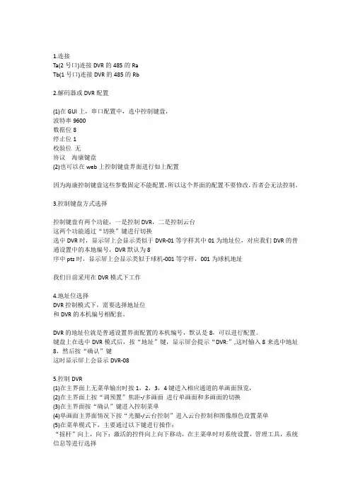
1.连接Ta(2号口)连接DVR的485的RaTb(1号口)连接DVR的485的Rb2.解码器或DVR配置(1)在GUI上,串口配置中,选中控制键盘,波特率9600数据位8停止位1校验位无协议海康键盘(2)也可以在web上控制键盘界面进行如上配置因为海康控制键盘这些参数固定不能配置,所以这个界面的配置不要修改,否者会无法控制。
3.控制键盘方式选择控制键盘有两个功能,一是控制DVR,二是控制云台这两个功能通过“切换”键进行切换选中DVR时,显示屏上会显示类似于DVR-01等字样其中01为地址位,对应我们DVR的普通设置中的本地编号,DVR默认为8序中ptz时,显示屏上会显示类似于球机-001等字样,001为球机地址我们目前采用在DVR模式下工作4.地址位选择DVR控制模式下,需要选择地址位和DVR的本机编号相配套。
DVR的地址位就是普通设置界面配置的本机编号,默认是8,可以进行配置。
键盘上在选中DVR模式后,按“地址”键,显示屏会提示“DVR:”,这时输入8来选中地址8,然后按“确认”键这时显示屏上会显示DVR-085.控制DVR(1)在主界面上无菜单输出时按1,2,3,4键进入相应通道的单画面预览,(2)在主界面上按“调预置”焦距-/多画面进行单画面和多画面的切换(3)在主界面按“确认”键进入控制菜单(4)单画面主界面情况下按“光圈-/云台控制”进入云台控制和图像颜色设置菜单(5)在菜单模式下,主要通过以下键进行操作:“摇杆”向上,向下:激活的控件向上向下移动,在主菜单时对系统设置,管理工具,系统信息等进行选择“摇杆”向左,向右:激活的控件向左向右移动,在主菜单时对系统设置等的子菜单进行选择,如普通设置,网络设置等“退出”回到上一级菜单“确认”确认或激活选中控件“调预置/录像”切换输入法,进入录像控制“雨刷/主菜单”删除错误输入0-9数字键进行数字输入,切换中英文输入法采用手动录像按钮要进行云台控制必须通过“光圈-/云台控制”或则“雨刷/主菜单”进入云台控制界面进行操作,可以采用摇杆进行方向移动,其他操作如设置预置点等和其他菜单相同。
海康威视系列硬盘录像机常用设置与操作1. 如何使用遥控?对准DVR面板,在遥控器上操作A、按设备键B、输入设备号88(默认设备号为88,可在主菜单-本地显示进行修改)C、按确认键如果遥控器配置成功,硬盘录像机前面板上的状态灯变为绿色。
再次按下设备键,停止遥控控制。
每次DVR重新上电后,遥控器需再次配置方可使用。
2. 为什么新机器开机后会有“嘀-嘀-嘀-嘀嘀”的声音,如何清除?原因:1:机器没有装硬盘;2:机器装了硬盘但没有进行格式化;3:硬盘坏。
清除办法:1:如果不需要装硬盘,请到主菜单-异常处理中,把硬盘错这个异常类型的声音告警打“×”;2:如果装了硬盘,请到主菜单-管理工具-硬盘管理中,把硬盘格式化;3:仍未解决,可能是硬盘坏,请更换硬盘。
3. 如何设置7×24小时自动录像?①进入主菜单-录像设置,选择录像通道,在开启录像选项后打“√”;②进入设置,在全天录像选项后打“√”设置录像类型为定时;③将复制该设置至:星期一中的星期一改成全部,点击复制,确定复制成功;④点击确定保存设置,并退出设置到录像设置界面。
⑤在录像设置界面中,把本通道录像设置复制到其它通道。
⑥点击确定保存设置。
4. 如何设置录像参数,如何计算录像文件大小?常用的录像参数有码流类型、分辨率、视频帧率、位率上限和位率类型,使用中根据设备功能选定支持的码流类型与合适的分辨率(详见“各类型的对比”);视频帧率一般为全帧率;位率类型有:定码流:按照设定的位率上限值进行压缩存储。
变码流:根据不同场景,即时自动改变录像分辨率、图像质量、码流和帧率,节省硬盘空间和网络带宽。
录像文件大小和“录像设置”中的位率大小和采用何种位率类型有关。
使用中根据所选择的分辨率来选择适当的位率大小:分辨率位率上限CIF 384K~768KbpsDCIF 512K~1Mbps4CIF 768K~2Mbps下表是在定码率下常见位率一个通道一个小时录像文件的大小。

报警问题处理操作手册主机键盘、警号、辅电无输出等问题目录一、操作流程(配置流程) (1)二、操作步骤(配置步骤) (1)1.主机正常上电初始化 (1)2.键盘无输出问题处理 (1)3.警号无输出问题处理 (2)4.辅电无输出问题处理 (3)三、适用型号 (3)四、变更记录 (3)五、关于海康威视 (1)一、操作流程(配置流程)1)主机正常上电初始化2)键盘无输出问题处理3)警号无输出问题处理4)辅电无输出问题处理二、操作步骤(配置步骤)1.主机正常上电初始化2.键盘无输出问题处理A.检查键盘接线(D+,D-,12V,G)是否一一对应,检查键盘是否注册成功。
B.确认拓扑中键盘接入数量,检查键盘拨码是否冲突。
备注:LED 键盘不支持总线报警主机,只支持网络报警主机和视频报警主机,且拨码必须为非0。
C.如果接入多个子系统键盘,规划了多个子系统,则需在4200 软件中检查子系统与键盘的关联情况。
3.警号无输出问题处理A.检查警号接线(BELL-----12V,G)B.检查警号关联设置(远程配置—报警—防区—防区参数设置—关联警号)C.如需关联子系统或全局事件,则在远程配置—报警—警号中设置D.如果接线和设置均无异常,同时检查保险丝是否烧断,部分防区生效,部分防区不生效,则有可能是程序异常导致,此类情况联系总部技术支持进行咨询确认。
4.辅电无输出问题处理A.检查确认主机是否正常工作,如果主机不正常工作则需检查主机电源后者主板是否损坏。
B.如果主机正常工作,检查主板上对应的保险管是否过载熔断。
C.注意:所有接至警号、辅助电源、键盘供电端的负载总电流不可以超过2500mA 附图:保险丝位置五、关于海康威视海康威视是以视频为核心的物联网解决方案提供商,面向全球提供综合安防、智慧业务与大数据服务。
海康威视全球员工超26000人(截止2017年底),其中研发人员和技术服务人员超13000人,研发投入占企业销售额的7-8%,绝对数额占据业内前茅。
海康威视SRM系统操作手册准入管理(供应商)2020年5月28日1目录1系统介绍 (3)1.1.客户端下载地址(注意区分32位和64位操作系统) (3)1.2.硬件要求(建议) (4)1.3.流程图 (5)2功能介绍 (6)3操作指南 (7)3.1.供应商注册 (7)3.2.供应商准入资料...................................................................................................... 错误!未定义书签。
3.3.常见问题: (14)21 系统介绍1.1.客户端下载地址(注意区分32位和64位操作系统)https:///SRM/NEW/?1588737082769/#/login/login.html单击下图“ELSBrowser”应用程序进入到客户端。
浏览器(务必使用谷歌Chrome浏览器)登录地址:https:///SRM/NEW/?1588737082769/#/login/login.html31.2.硬件要求(建议)45供应商管理-准入流程采购方供应方开始03 注册ELS账号04 填写基本资料信息02 邀请供应商注册ELS 账号01 搜索ELS 平台供应商05 审核基本信息修正基本信息07 创建供应商准入单合作09 填写准入资料10 审核准入资料11 现场审核13 综合评分12 录入审核结果通过15 成为临时/正式供应商维护主数据17 同步供应商主数据到ERP结束Y可改善06 成为潜在供应商01/02 资源工程师03/04 供应商05/06 资源工程师07/08 资源工程师09 供应商10 资源工程师11/12 资源工程师/SQE/硬件工程师13 资源工程师14 资源工程师/SQE 15 资源工程师16 资源主管/经理17 资源工程师结束不合作08 需供应商自评?是否14 辅导改善终止16 审批通过通过不通过供应商主数据框架协议2 功能介绍子账号说明(1001账号可以解冻,解锁和更新1002-1006子账号):1001子账号:供应商管理员账号,具备所有的操作权限,包括供应商的企业信息变更等;1002子账号:供应商针对供应链金融的账号,包括可以操作供应链金融业务,提前支付;1003子账号:供应商针对海康资源工程师之间业务对接,包括询报价、招投标、合同、业务伙伴管理等;1004子账号:供应商针对研发业务之间的业务对接,包括样品、ECN管理、合规管理等业务;1005子账号:供应商针对品质业务之间的业务对接,包括质量管理业务等;1006子账号:供应商针对仓库业务之间的业务对接,包括周转箱APP业务等。
IP SAN/NAS 存储产品快速使用手册(Version 1.0)杭州海康威视数字技术有限公司地址:浙江省杭州市马塍路36号电话:86(571)-88075998传真:86(571)-88805843网址:目录一. 硬件安装 (1)1. 硬件子系统 (1)2. 开机和关机 (2)二. 设定海康威视IP SAN/NAS的访问IP (3)三. DVR存储空间使用说明 (3)四. 建立对海康威视IP SAN/NAS存储系统iSCSI的连接 (11)五. 建立对海康威视IP SAN/NAS 的NAS连接 (16)六. 常见疑问解答 (18)七. 备注 (19)一. 硬件安装1.硬件子系统海康威视网络存储设备包括硬件子系统和软件子系统两部分,它们的安装可以独立进行,不需要按照固定的顺序去实施。
软件子系统是海康威视公司为网络存储设备而开发出来的网络存储管理系统,在网络环境中部署海康威视网络存储设备就可以正常地完成对存储的管理功能。
硬件子系统主要采用机架式机箱,以DS-A1008R为例,它内含8个硬盘槽位,通过状态指示灯可以很直观的查看系统电源,网络和磁盘等状态。
详见下图:DS-A1008R前面板图安装准备:在开始安装前,请检查以下物品是否齐全:1. 海康威视网络存储设备2. 电源线3. 千兆(百兆)网线(网线推荐用超五类(CAT 5e)线)4. 产品合格证5. 产品保修卡6. 快速使用手册以下物品需自备或选配:1. 千兆交换机(用户自备,普通的二层交换机即可)2. 机架导轨(选配件,标配不含)磁盘安装:为了保证运输安全,建议您将磁盘和海康威视网络存储设备分开包装。
请按照以下步骤安装磁盘:1. 向左按压磁盘固定弹簧扣,打开拉杆,将磁盘架沿导轨从机箱中拔出来;2. 用4个螺丝把硬盘固定到硬盘架上;3. 将硬盘架插入机箱,沿导轨推到底,并按压拉杆,以确保硬盘放到位并锁好;4. 重复以上操作,直到所有的硬盘安装完成。

Control Terminal- TPE100User ManualUD.6L0201D1989A01User ManualCOPYRIGHT ©2015 Hangzhou Hikvision Digital Technology Co., Ltd.ALL RIGHTS RESERVED.Any and all information, including, among others, wordings, pictures, graphs are the properties of Hangzhou Hikvision Digital Technology Co., Ltd. or its subsidiaries (hereinafter referred to be “Hikvision”). This user manual (hereinafter referred to be “the Manual”) cannot be reproduced, changed, translated, or distributed, partially or wholly, by any means, without the prior written permission of Hikvision. Unless otherwise stipulated, Hikvision does not make any warranties, guarantees or representations, express or implied, regarding to the Manual.About this ManualThis Manual is applicable to Control Terminal DS-TPE100.The Manual includes instructions for using and managing the product. Pictures, charts, images and all other information hereinafter are for description and explanation only. The information contained in the Manual is subject to change, without notice, due to firmware updates or other reasons. Please find the latest version in the company website (/en/).Please use this user manual under the guidance of professionals.Trademarks Acknowledgementand other Hikvision’s trademarks and logos are the properties of Hikvision in various jurisdictions. Other trademarks and logos mentioned below are the properties of their respective owners.Legal DisclaimerTO THE MAXIMUM EXTENT PERMITTED BY APPLICABLE LAW, THE PRODUCT DESCRIBED, WITH ITS HARDWARE, SOFTWARE AND FIRMWARE, IS PROVIDED “AS IS”, WITH ALL FAULTS AND ERRORS, AND HIKVISION MAKES NO WARRANTIES, EXPRESS OR IMPLIED, INCLUDING WITHOUT LIMITATION, MERCHANTABILITY, SATISFACTORY QUALITY,FITNESS FOR A PARTICULAR PURPOSE, AND NON-INFRINGEMENT OF THIRD PARTY. IN NO EVENT WILL HIKVISION, ITS DIRECTORS, OFFICERS, EMPLOYEES, OR AGENTS BE LIABLE TO YOU FOR ANY SPECIAL, CONSEQUENTIAL, INCIDENTAL, OR INDIRECT DAMAGES, INCLUDING, AMONG OTHERS, DAMAGES FOR LOSS OF BUSINESS PROFITS, BUSINESS INTERRUPTION, OR LOSS OF DATA OR DOCUMENTATION, IN CONNECTION WITH THE USE OF THIS PRODUCT, EVEN IF HIKVISION HAS BEEN ADVISED OF THE POSSIBILITY OF SUCH DAMAGES.REGARDING TO THE PRODUCT WITH INTERNET ACCESS, THE USE OF PRODUCT SHALL BE WHOLLY AT YOUR OWN RISKS. HIKVISION SHALL NOT TAKE ANY RESPONSIBILITES FOR ABNORMAL OPERATION, PRIVACY LEAKAGE OR OTHER DAMAGES RESULTING FROM CYBER ATTACK, HACKER ATTACK, VIRUS INSPECTION, OR OTHER INTERNET SECURITY RISKS; HOWEVER, HIKVISION WILL PROVIDE TIMELY TECHNICAL SUPPORT IF REQUIRED.SURVEILLANCE LAWS VARY BY JURISDICTION. PLEASE CHECK ALL RELEVANT LAWS IN YOUR JURISDICTION BEFORE USING THIS PRODUCT IN ORDER TO ENSURE THAT YOUR USE CONFORMS THE APPLICABLE LAW. HIKVISION SHALL NOT BE LIABLE IN THE EVENT THAT THIS PRODUCT IS USED WITH ILLEGITIMATE PURPOSES.IN THE EVENT OF ANY CONFLICTS BETWEEN THIS MANUAL AND THE APPLICABLE LAW, THE LATER PREVAILS.Regulatory InformationFCC InformationFCC compliance: This equipment has been tested and found to comply with the limits for a digital device, pursuant to part 15 of the FCC Rules. These limits are designed to provide reasonable protection against harmful interference when the equipment is operated in a commercial environment. This equipment generates, uses, and can radiate radio frequency energy and, if not installed and used in accordancewith the instruction manual, may cause harmful interference to radio communications. Operation of this equipment in a residential area is likely to cause harmful interference in which case the user will be required to correct the interference at his own expense.FCC ConditionsThis device complies with part 15 of the FCC Rules. Operation is subject to the following two conditions:1. This device may not cause harmful interference.2. This device must accept any interference received, including interference that may cause undesired operation.EU Conformity StatementThis product and - if applicable - the supplied accessories too aremarked with "CE" and comply therefore with the applicableharmonized European standards listed under the EMC Directive 2004/108/EC, the RoHS Directive 2011/65/EU.2012/19/EU (WEEE directive): Products marked with this symbolcannot be disposed of as unsorted municipal waste in the EuropeanUnion. For proper recycling, return this product to your localsupplier upon the purchase of equivalent new equipment, or dispose of it at designated collection points. For more information see: .2006/66/EC (battery directive): This product contains a battery thatcannot be disposed of as unsorted municipal waste in the EuropeanUnion. See the product documentation for specific batteryinformation. The battery is marked with this symbol, which may include lettering to indicate cadmium (Cd), lead (Pb), or mercury (Hg). For proper recycling, return the battery to your supplier or to a designated collection point. For more information see: .Industry Canada ICES-003 ComplianceThis device meets the CAN ICES-3 (A)/NMB-3(A) standards requirements.Safety InstructionThese instructions are intended to ensure that the user can use the product correctly to avoid danger or property loss.The precaution measure is divided into ‘Warnings’ and ‘Cautions’:Warnings: Serious injury or death may be caused if any of these warnings are neglected.Cautions: Injury or equipment damage may be caused if any of these cautions are neglected.Follow theseprevent serious injury or death. Follow these potential injuryWarnings:●Do not drop the device or subject it to physical shock.●Proper configuration of all passwords and other security settings is theresponsibility of the installer and/or end-user.●In the use of the product, you must be in strict compliance with the electricalsafety regulations of the nation and region. Please refer to technical specifications for detailed information.●Input voltage should meet both the SELV (Safety Extra Low V oltage) and theLimited Power Source with 100~240 V AC, 48 VDC or 12 VDC according to the IEC60950-1 standard. Please refer to technical specifications for detailed information.●Do not connect several devices to one power adapter as adapter overload maycause over-heating or a fire hazard.●Please make sure that the plug is firmly connected to the power socket.●If smoke, odor or noise rise from the device, turn off the power at once andunplug the power cable, and then please contact the service center.Cautions:●Read the manual carefully before you use the device.●Make sure the device power is turned off and the plug is unplug from the powersocket when you do the operations, including plug or remove the board card.●Make sure the device power is turned off when plug or unplug any cables.●Wait at least 30 seconds to power on the device if the device is newly shut downto avoid the device damage by frequent power off/power on.●For some precise unit is quite sensitive to the ESD, make sure electrostaticdischarge has been finished if you want to dismount or assemble the device.●If no ESD workbench is provided, you can follow the tips below to lower thedamage might be caused by ESD.o Wear a wrist strap, and touch the metal parts of the device with the wrist strap.o Touch the metal part on the machine instead of the components.o Avoid the unnecessary walking around.o Hold the edge of the components, especially for the board card.o Put all the components on a conducting foam pad.o Move the components on the workbench as less as possible.●It is recommended that you use a magnetic cross screwdriver to tighten or loosenthe screws. Make sure no tool or components are left in the machine.●Keep the device away from water and any liquid.●While shipping, the device should be packed in its original packing.●Improper use or replacement of the battery may result in hazard of explosion.●Ensure unit is installed in a well-ventilated, dust-free environment.●Ensure unit is properly secured to a rack or shelf. Major shocks or jolts to the unitas a result of dropping it may cause damage to the sensitive electronics within theunit.●Use the device in conjunction with an UPS if possible.●Power down the unit before connecting and disconnecting accessories andperipherals.● A factory recommended HDD should be used for this device.Table of ContentsChapter 1About This Manual (8)Chapter 2Introduction (9)2.1Product Overview (9)2.2Performance (9)2.3Specification (10)2.4Shipping & Storage Requirement (11)Chapter 3Installation (12)3.1Appearance (12)3.2Dimension (12)3.3Interface Description (13)3.4Assembling HDD (14)3.5Assembling the Device (15)Chapter 1About This Manual PurposeThis document introduces the DS-TPE100 Control Terminal and relevant settings of the product.Intended AudienceThis document is intended for:Technical support engineersMaintenance engineersChapter 2Introduction2.1Product OverviewWith the features of low consumption and high performance, DS-TPE100 is designed for entrance/exit control. Adopting the strong aluminum alloy extrusions without fans on its body, the control terminal has a compact structure with good heat dissipation. The control terminal is applicable to the challenging environment of dusty and high electromagnetic interference.Figure 2-1Overview of Control Terminal2.2PerformanceCPU:Intel® CPU Bay Trail-D J1900 with integrated MC and GPU.CS:Intel® CPU Bay Trail-D J1900Memory:4GB DDR3L, with memory frequency of 1333MHzEthernet Interface:10/100/1000Mbps Self-adaptiveDisplay:Integrated Graphics Processing UnitVGA, with max. resolution and fresh rate of 2560×1600@60HzHDMI, with max. resolution and fresh rate of 1920x1080@60HzAudio:Standard HD, support LINE-IN/LINE-OUTAvailable interfaces:2 10/100/1000Mbps Ethernet interfaces, and 4 10M/100Mbps Ethernet interfaces 4 USB2.0 interfaces2 RS485 interfaces3 RS232 interfaces1 VGA interface1 HDMI interface1 audio interface (LINE-in/Line-out)1 12V DC power inputOthers:3.5’ HDD(1 pcs),Adapter (60w)Consumption:40W at max.2.3SpecificationDimension & Weight:Dimension: 245mm(L)*170mm(W)*65mm(H)Weight: 4.05kgWorking Environment:Temperature: -20°C~55°CHumidity: 10%~90% (Non-condensation)Storing Environment:Temperature: -40°C~80°CHumidity: 10%~90% (Non-condensation)Electromagnetic compatibility:GB9254-2008, radiation disturbance (A), conducted disturbance(A)GB/T17626.2-2006 ESD (2)GB/T17626.4-2008 EFT (2)GB/T17626.5-2008SURGE(2)GB/T17626.6-2008CS (2)GB/T17626.11-2008, auto disconnected when voltage dip, voltage short circuit Reliability:MTBF≥50000hSafety:GB4943Environmental Suitability:Anti-vibration: 5-19Hz/1.0mm amplitude, 19-200Hz/1.0g accelerated speedShock Resistance: 10g accelerated speed, 11ms period2.4Shipping & Storage Requirement●ShippingIt is recommended that the device is packed in its original packing when shipping. Make sure the device is away from the flammable, combustible and corrosive objects, and the rain, snow, and liquid as well.●StoringIt is recommended that the device is packed in its original packing when storing. The ideal storing temperature is -40°C~80°C, and the ideal storing humidity is 10%~90%.Keep the device away from the flammable, combustible and corrosive objects, and the storing environment should be free of the strong mechanical resonance and strong magnetic.The device package should be underlay at least 10cm from the ground. And it should be at least 50cm away from the wall, heat source, cold source, and window or air inlet.Chapter 3Installation 3.1AppearanceThe device appearance is shown below.Figure 3-1Appearance3.2DimensionFigure 3-2Dimension3.3Interface Description12356478910111213151614Figure 3-3Interface Introduction Figure 3-4Interface Description3.4Assembling HDDFigure 3-5Assemble the HDDAssemble the HDD first before you install the HDD to the device.Steps:1.Align the copper foil to one side of the HDD, and fix the thermal pad to the motorpart.2.Fix the crash pads to the HDD radiator.3.Secure the HDD to the HDD radiator.4.Install the copper foil to the other side of the HDD.3.5Assembling the DeviceFront CoverFigure 3-6Main ComponentsSteps:1.Align the PCB board with the standoffs, and secure the PCB board by tighteningthe lock screws.2.Align the thermal module with the standoffs, and secure the thermal module withby tightening the lock screws.3.Install the HDD to the standoffs, and tighten the lock screws.4.Connect the HDD cables to the corresponding interfaces.5.Align the front cover to the interfaces of the PCB board, and tighten the lockscrews.6.Install the fixed strip, align the upper cover to the lower cover, and secure theupper cover and lower cover by tightening the lock screws.7.Install the grounding screws.。

控制键盘用户使用手册(V2. 1版)在连接和使用本设备前,请仔细阅读本使用手册并妥善保存以备日后参考。
功耗 最大IOW最大IOW尺寸320 (宽)×108 (深)×93 (高)360 (宽)×196 (深)XllO (高) 重量2. 50Kg2. 90Kg164. 2控制DVRΛ本操作手册可能包含技术上不准确的地方或印刷错误。
本 手册的内容将做不定期的更新,恕不另行通知:更新的内容将 会在本手册的新版中加入。
我们随时会改进或更新本手册中描 述的产品或程序。
第一台DvRKB 口般(或keyhard 口的第4芯)JfO-.⅛DVRKBOftD - (.或k )t (wd 口的第一台DVRKB 口的D ♦(或ke>M 口的第3芯) 并屈β二台DVRKB 口的D÷ (必球KMrd 口的粕芯) 最多可级联挖柏怡DVR注意事项K液晶显示屏为易损体,切勿挤压,或长久时间内在强光下照晒:2、摇杆为易损体,返修时,切记使用原包装或妥善包装好后再托运;3、让控制键盘在技术指标允许的温度及湿度范国内工作;4、请严格按照本手册的接线方式连接。
目录第1章功能简介 (2)第2章安装说明 (3)1.1后面板接口说明 (4)2. 2 DS-Ioo2K前面板说明 (4)3. 2.1按键功能说明 (5)4. 2.2摇杆控制说明 (6)5. 2.3液晶屏显示说明 (6)6. 3 DS-IOO3K前面板说明 (7)7. 3.1按键功能说明 (7)8. 3.2摇杆控制说明 (9)9. 3.3液晶屏显示说明 (10)第三章键盘设置与查询 (10)9.1键盘菜单结构 (10)10.2设置举例 (12)第四章典型接线图示 (14)11.1控制快球 (14)4.2 控制 DvR (15)第五章技术参数 (16)第四章典型接线图示4. 1控制快球9、修改设置完成。
DVR:OI球机设置!.健盘设置球机地址: 002-P:PELCoP BR:096(Sg)DVRrOl输入密码(Ib)球机地址:OOIP I PELCOP BR:096(≡)球机地址:002P:PELCOD BR:096DVR:01输入密码♦ * * *(≡球机地址:002PrPELCOP BR:096≡f)球机地址: 002^P:PELCOD BR:096(S?)13第一章功能简介功能简介(图h)球机地址:002 P:PELCOD BR:048二维键盘、三维键盘控制键盘全面兼容本公司所有系列的嵌入式硬盘录像机。
键盘拨码及常用操作手册目录一、操作流程(配置流程) (1)二、操作步骤(配置步骤) (1)三、适用型号 (3)四、变更记录 (3)五、关于海康威视 (1)一、操作流程(配置流程)1)主机及键盘匹配性确认2)键盘拨码3)键盘常用操作二、操作步骤(配置步骤)1.主机及键盘匹配性确认A.LED 键盘不支持总线报警主机,只支持网络报警主机和视频报警主机,且拨码必须为非0(拨码1-31)。
B.LCD 键盘拨码为0 则为全局键盘,非0 拨码则为子系统键盘(拨码1-31)。
C.系统配用的每一个报警键盘都必须有一个地址,这些地址不能重复。
当更换报警键盘的时候,须确保更换的报警键盘与前一个报警键盘地址相同。
在系统上电前,通过键盘的拨码开关给键盘设置地址,在键盘上设置0 到31 之间的任一地址值,所选地址值超出规定范围将不被接受。
2.键盘拨码(需要拆开键盘进行拨码设置,二进制拨码对应表如下所示)五、关于海康威视海康威视是以视频为核心的物联网解决方案提供商,面向全球提供综合安防、智慧业务与大数据服务。
海康威视全球员工超26000人(截止2017年底),其中研发人员和技术服务人员超13000人,研发投入占企业销售额的7-8%,绝对数额占据业内前茅。
海康威视是博士后科研工作站单位,以杭州为中心,建立辐射北京、上海、重庆、武汉以及加拿大蒙特利尔、英国利物浦的研发中心体系,并计划在西安、武汉、成都、重庆和石家庄建立新的研发基地。
海康威视拥有视音频编解码、视频图像处理、视音频数据存储等核心技术,及云计算、大数据、深度学习等前瞻技术,针对公安、交通、司法、文教卫、金融、能源和智能楼宇等众多行业提供专业的细分产品、IVM智能可视化管理解决方案和大数据服务。
在视频监控行业之外,海康威视基于视频技术,将业务延伸到智能家居、工业自动化和汽车电子等行业,为持续发展打开新的空间。
海康威视在中国大陆拥有32家省级业务中心/一级分公司,在境外有38 个分支机构(截止2018年9月30日)。
NVR操作手册UD.6L0102C1272A01版权所有?杭州海康威视数字技术股份有限公司 2016。
保留一切权利。
本手册的任何部分,包括文字、图片、图形等均归属于杭州海康威视数字技术股份有限公司或其子公司(以下简称“本公司”或“海康威视”)。
未经书面许可,任何单位和个人不得以任何方式摘录、复制、翻译、修改本手册的全部或部分。
除非另有约定,本公司不对本手册提供任何明示或默示的声明或保证。
关于本手册本手册描述的产品仅供中国大陆地区销售和使用。
本手册作为指导使用。
手册中所提供照片、图形、图表和插图等,仅用于解释和说明目的,与具体产品可能存在差异,请以实物为准。
因产品版本升级或其他需要,本公司可能对本手册进行更新,如您需要最新版手册,请您登录公司官网查阅()。
海康威视建议您在专业人员的指导下使用本手册。
商标声明为海康威视的注册商标。
本手册涉及的其他商标由其所有人各自拥有。
责任声明●在法律允许的最大范围内,本手册所描述的产品(含其硬件、软件、固件等)均“按照现状”提供,可能存在瑕疵、错误或故障,海康威视不提供任何形式的明示或默示保证,包括但不限于适销性、质量满意度、适合特定目的、不侵犯第三方权利等保证;亦不对使用本手册或使用本公司产品导致的任何特殊、附带、偶然或间接的损害进行赔偿,包括但不限于商业利润损失、数据或文档丢失产生的损失。
●若您将产品接入互联网需自担风险,包括但不限于产品可能遭受网络攻击、黑客攻击、病毒感染等,海康威视不对因此造成的产品工作异常、信息泄露等问题承担责任,但本公司将及时为您提供产品相关技术支持。
●使用本产品时,请您严格遵循适用的法律。
若本产品被用于侵犯第三方权利或其他不当用途,本公司概不承担任何责任。
●如本手册内容与适用的法律相冲突,则以法律规定为准。
前言本节内容的目的是确保用户通过本手册能够正确使用产品,以避免操作中的危险或财产损失。
在使用此产品之前,请认真阅读产品手册并妥善保存以备日后参考。
快速使用指南一、注意事项●DVR主机应放置在足够通风的空间●机房温度在-10℃~+55℃,湿度在10%~90%●定期对DVR主机内灰尘用刷子清除●定期对DVR主机内灰尘用刷子清除二、DVR主机功能1、主机正面各功能键说明(见图示)上图说明:●USB接口作用:用于连接USB设备,比如U盘、USB接口的移动硬盘等。
●状态灯1作用:通道1~16的状态显示,绿色表示正在录像,红色表示正在网传,橙色表示既录像又网传。
●显示屏作用:显示系统当前信息。
●控制键作用:①上“↑”、下“↓”、左“←”、右“→”用于回放时控制快放、慢放、快进、快退和云台方向的控制(本系统不需要使用云台),其中“←”和“→”键在菜单模式中用于移动菜单设置项的活动框。
②键中间的“确认”键是在菜单模式中确认操作和选择框状态√与X之间切换以及回放时作为暂停用的。
●开关键作用:设备开关具有电源指示灯功能,绿色表示设备正在工作,红色设备停止工作,此指示灯不亮表示主机后面的电源开关没有打开或者电源没有接上。
●输入键作用:用于输入数字、大小写英文字母等。
●状态灯2这六个状态灯分别意义为:①“就绪”灯亮表示设备处于就绪状态;②“状态”灯亮(绿色)表示处于遥控器操作状态;③“报警”灯亮,表示有报警信号输入(本系统无此功能);④“MODEM”是网络使用时的指示灯,本系统没有使用网络;⑤“硬盘”当硬盘正在读写时,此灯红呈色闪烁;⑥“网络”和“网传”这两个灯因系统没有使用网络,所以不会亮。
●复合键作用:①“主菜单/雨刷”键是用于预览界面到菜单界面的切换,“雨刷”是启动摄像机上的雨刮器用的,本系统使用的摄像机不需要雨刮器;②“退出”键是取消当前操作返回到上一级菜单用的;③“编辑/光圈+”选择框状态√与X之间的切换;④“输入法/焦距+”第一个作用是输入法(数字、英文、中文、符号)之间的切换,第二个作用是调整焦距(本系统不需要),第三个作用是在预览界面中显示或隐藏通道状态;⑤“变倍+”键,此键在本系统无作用;⑥“放像/自动”键,回放时用;⑦“录像/预制点”键是手动录像用;⑧“云台控制/光圈-”键在本系统无作用;⑨“多画面/焦距-”键在预览状态可以多画面切换,第二个作用是可以从菜单模式切换到预览界面;⑩“辅口/变倍-”键在本系统无作用。