matlab制作信号发生器
- 格式:ppt
- 大小:9.66 MB
- 文档页数:38
三.信号发生器设计
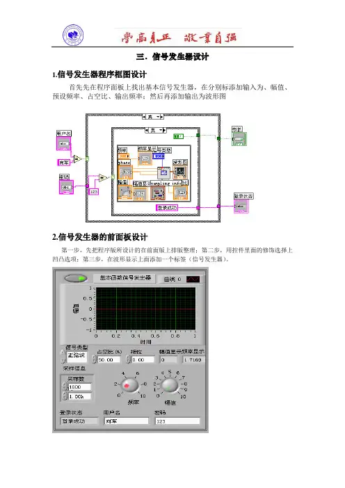
1.信号发生器程序框图设计
首先先在程序面板上找出基本信号发生器,在分别标添加输入为、幅值、预设频率、占空比、输出频率;然后再添加输出为波形图
2.信号发生器的前面板设计
第一步,先把程序版所设计的在前面版上排版整理;第二步,用控件里面的修饰选择上凹凸选项;第三步,在波形显示上面添加一个标签(信号发生器)。
运行结果:
三角波
正选波
方波
锯齿波
3.结束语
设计的信号发生器可以实现在波形显示波形信号, 信号的相位和幅值还有频率均可自己调试。
适合于科研分析。
基于Matlab/DSP Builder的正弦信号发生器设计引言近年来随着通信技术的不断发展,信号的正确传输显得日益重要,也就是说要有一个可靠的能产生稳定确信号的发生器,基于Matlab/DSP Builder的正弦信号发生器是利用Matlab/DSP Builder的模块进行的模快化设计,软件的设计采用模块化结构,使程序设计的逻辑关系更加简洁明了、易懂、易学。
使硬件在软件的控制下协调运作。
DSP Builder可以帮助设计者完成基于FPGA的DSP系统设计设计,除了图形化的系统建模外,还可以完成及大部分的设计过程和仿真,直至将设计文件下载到DSP开发板上。
此次实验的目的就是将两者的优势有机的结合在一起,利用DSP的优势开发正弦信号发生器。
在设计中主要采用DSP Builder库中的模块进行系统的模型设计,然后再进行Simulink仿真。
1.设计思想1.1 DSP Builder特点DSP Builder系统级(或算法级)设计工具,它架构在多个软件工具之上,并把系统级(算法仿真建模)和RTL(硬件实现)两个领域的设计工具连接起来,最大程度的发挥了两种工具的优势。
DSP Builder依赖于MathWorks公司的数学分析工具Matlab/Simulink,可以在Simulink中进行图形化设计和仿真,同时又通过Signal Compilder把Matlab/Simulink的设计文件(.mdl)转换成相应的硬件描述语言VHDL设计文件(.vhd),以及用于控制和编译的tcl脚本。
而对后者的处理可以用Quartus II来实现。
1.2 QuartusII特点QuartusII提供了完整的多平台设计环境,能满足各种特定设计的需要,是单芯片可编程系统(SOPC)设计的综合性环境和SOPC开发的基本设计工具,并且为Altera DSP开发包进行系统模型设计提供了集成综合环境。
QuartusII完全支持VHDL的设计流程,其内部嵌有VHDL逻辑综合器。

基于MATLAB的函数信号发生器1信息系统仿真设计实训报告学院信息电子技术专业****班级******8学号********8姓名***指导教师***2014年7月25日基于MATLAB的函数信号发生器1、目的函数信号发生器是基于软硬件实现的一种波形发生仪器。
在工工程实践中需要检测和分析的各种复杂信号均可分解成各简单信号之和,而这些简单信号可由函数信号发生器模拟产生,因此它在工程分析和实验教学有着广泛的应用。
MATLAB 是一个数据分析和处理功能十分强大的工程实用软件,他的数据采集工具箱为实现数据的输入和输出提供了十分方便的函数和命令,在信号处理方面方便实用。
本文介绍了使MATLAB建立一个简单函数信号发生器的基本流程,并详细叙述了简单波形(正弦波、方波、三角波、锯齿波、白噪声、脉冲)信号的具体实现方法。
通过此次的设计对MATLAB有个更深刻的了解,熟练的使用MATLAB的GUI设计简单的界面程序。
2、工作原理与计算该虚拟信号发生器的设计由GUI界面及其对应的程序组成。
设计函数发生器有正弦信号、方波信号、三角波、锯齿波、白噪声、脉冲信号。
其中,前五种波形都可以利用MATLAB提供的函数实现,并根据输入的幅值、相位、频率等信息进行调整。
根据脉冲信号在某一时刻出现的一冲激特点,可由编写程序来实现。
界面主要由MATLAB创建,之后编写界面所用的函数,从而实现函数信号发生器。
(1)正弦信号的实现正弦波信号的数学表达式如(1)。
ωφ()其中:A为幅值;ω为频率; 为相位。
在MATLAB中,幅值、频率、相位、在用户界面输入。
y的表达式都得到以后,用plot二维作图函数获得波形显示。
(2)方波信号的实现与正弦波一样,从用户界面获得幅值、频率、相位、采样频率等信息,用square 函数获得对应y坐标值,用plot绘图,格式如(2)。
()其中duty为占空比。
(3)三角波和锯齿波的实现这两种波形的表达式皆要借助于sawtooth命令。


基于matlab的信号发⽣器设计Digital Signal GeneratorYangXiao M2013705103HuaZhong University of Science and TechnologySchool of Mechanical Science and Engineering Abstract: Matlab Is a numerical analysis, matrix calculation, scientific data visualization and nonlinear dynamic state system modeling and simulation, and other functions of practical software engineering.It’s easy to use the windows environment and cast off a tradition on the interactive programming language (such as C, Fortran) Edit mode In large range. In this report,The task is to design a digital signal generator bu using matlab.It could help us to understand the signal processing by designing the digital signal generator. Which has a certain application value of reference.Keyword:digital signal generator;Matlab1.PrefaceMATLAB is called Matrix Laboratory,which is designed by the United States MathWorks company.It’s a commercial mathematical software. Matlab can be use for Matrix operations, mapping functions and data, algorithm, creating the user interface, connect to other programming languages procedures, mainly used in engineering calculations, control design, signal processing and communications, image processing, signal detection, design and financial modeling analysis and other fields. GUI (Graphical User Interface, referred to as GUI, known Graphical User Interface) is displayed using the graphical user interface of computer operations.. Matlab has a powerful GUl tool. In this report, by using matlab GUI tool we could a designed digital signal generator .2. IntroduceProgram reference implementation of MATLAB Data Acquisition Toolbox. In MATLAB design, there are two designs: the GUI editor and M-file write. This design use GUI editor . The GUI is user interface, which is to select the waveform, set and modify the waveform parameters, set the sampling rate, select the output channel and run. This program GUI interface provided: sin, square, triangle, sawtooth, while noise, to choice. Also we could change waveform parameters to change waveform’s shape. As frequency amplitude phase and sample haveprovided gave us to change.The interface is that:2.1 Interface3. Design PrinciplesThe task is to design the digital signal generator which can generate sine wave, square wave, triangle wave, sawtooth wave, and white noise. All the waveform can use MATLAB function, and could be adjusted by inputting information such as the amplitude, phase and frequency .3.1 Achieve sin signalThe mathematical function of sin wave signal is that:()sin 2y A ft πφ=+A: amplitude; f: frequency;φ: phase;t: 0:1/s:1;(s is sample); The M-program is:A=get(handles.Amplitude,'Value'); f=get(handles.Frequency,'Value'); p=get(handles.Phase,'Value');s=get(handles.Sample,'Value'); x=0:1/s:1;y=A*sin(2*pi*f*x+p); plot(handles.screen,x,y,'r'); legend('sin(x)'); wavplay(y); grid on;axis([0,0.1,-20,20]);We could run the program by setting the parameters:3.1 Image of sin signal3.2 Achieve square signalThe mathematical function of square wave signal is that:(2)y Asquare ft b π=+A: amplitude; f: frequency; b: phase;t: 0:1/s:1;(s is sample); The M-program is:A=get(handles.Amplitude,'Value'); f=get(handles.Frequency,'Value');p=get(handles.Phase,'Value');s=get(handles.Sample,'Value');x=0:1/s:10;y=A*square(2*pi*f*x+p);plot(handles.screen,x,y,'b');legend('square');wavplay(y);grid on;axis([0,0.1,-20,20]);We could run the program by setting the parameters:3.2 Image of square signal3.3 Achieve triangular signalThe mathematical function of triangular wave signal is that:(2,0.5)y Asawtooth ft b π=+A: amplitude; f: frequency; b: phase;t: 0:1/s:1;(s is sample); The M-program is:A=get(handles.Amplitude,'Value'); f=get(handles.Frequency,'Value'); p=get(handles.Phase,'Value'); s=get(handles.Sample,'Value'); x=0:1/s:10;y=A*sawtooth(2*pi*f*x+p,0.5); plot(handles.screen,x,y,'b'); legend(‘triangle ’); wavplay(y); grid on; axis([0,0.1,-20,20]);We could run the program by setting the parameters:3.3 Image of triangular signal3.4 Achieve sawtooth signalThe mathematical function of sawtooth wave signal is that:(2)y Asawtooth ft b π=+A: amplitude; f: frequency; b: phase;t: 0:1/s:1;(s is sample); The M-program is:A=get(handles.Amplitude,'Value'); f=get(handles.Frequency,'Value'); p=get(handles.Phase,'Value');s=get(handles.Sample,'Value');x=0:1/s:10;y=A*sawtooth(2*pi*f*x+p);plot(handles.screen,x,y,'b');legend(‘tooth’);wavplay(y);grid on;axis([0,0.1,-20,20]);We could run the program by setting the parameters:3.4 Image of sawtooth signal3.5 Achieve white noise signalThe mathematical function of white noise wave signal is that:y A rand length x=-2((1,())0.5)A: amplitude;f: frequency;b: phase;t: 0:1/s:1;(s is sample);The M-program is:A=get(handles.Amplitude,'Value');f=get(handles.Frequency,'Value');p=get(handles.Phase,'Value');s=get(handles.Sample,'Value');x=0:1/s:10;y=2* A*(rand(1,length(x))-0.5);plot(handles.screen,x,y,'b');legend('white noise');wavplay(y);grid on;axis([0,0.1,-20,20]);We could run the program by setting the parameters:3.5 Image of white noise signal4 Exist problemThere are many problems in the design because I didn’t use matlab and the GUI modules ever.(1) I am not familiar to the interface and operator of matlab,which lead toI program without efficiency.(2) Without systematic studying of matlab,I could not express my ideas by using succinct matlab language.(3)In the beginning, I don’t understand the handle deep, and don,t have aclear idea.5. ConclusionIn the latter study, I will be more systematic learning MATLAB this powerful engineering software, has a fight on his understanding of the macro, on the basis of multi-programming exercises to strengthen the commonly used functions and concepts of memory, and finally, contact practical, try to solve some common engineering problems.References[1] 薛⼭. MATLAB基础教程. [M] 北京:清华⼤学出版社,2011.3。
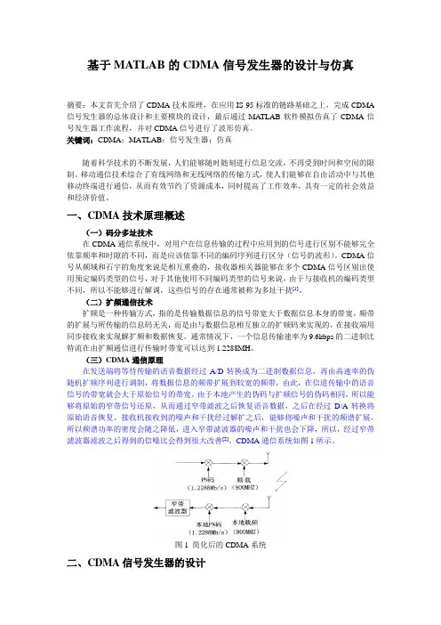
基于MATLAB的CDMA信号发生器的设计与仿真摘要:本文首先介绍了CDMA技术原理,在应用IS-95标准的链路基础之上,完成CDMA 信号发生器的总体设计和主要模块的设计,最后通过MATLAB软件模拟仿真了CDMA信号发生器工作流程,并对CDMA信号进行了波形仿真。
关键词:CDMA;MATLAB;信号发生器;仿真随着科学技术的不断发展,人们能够随时随刻进行信息交流,不再受到时间和空间的限制。
移动通信技术综合了有线网络和无线网络的传输方式,使人们能够在自由活动中与其他移动终端进行通信,从而有效节约了资源成本,同时提高了工作效率,具有一定的社会效益和经济价值。
一、CDMA技术原理概述(一)码分多址技术在CDMA通信系统中,对用户在信息传输的过程中应用到的信号进行区别不能够完全依靠频率和时隙的不同,而是应该依靠不同的编码序列进行区分(信号的波形)。
CDMA信号从频域和石宇的角度来说是相互重叠的,接收器相关器能够在多个CDMA信号区别出使用预定编码类型的信号,对于其他使用不同编码类型的信号来说,由于与接收机的编码类型不同,所以不能够进行解调,这些信号的存在通常被称为多址干扰[1]。
(二)扩频通信技术扩频是一种传输方式,指的是传输数据信息的信号带宽大于数据信息本身的带宽,频带的扩展与所传输的信息码无关,而是由与数据信息相互独立的扩频码来实现的,在接收端用同步接收来实现解扩频和数据恢复。
通常情况下,一个信息传输速率为9.6kbps的二进制比特流在由扩频通信进行传输时带宽可以达到1.2288MH。
(三)CDMA通信原理在发送端将等待传输的语音数据经过A/D转换成为二进制数据信息,再由高速率的伪随机扩频序列进行调制,将数据信息的频带扩展到较宽的频带,由此,在信道传输中的语音信号的带宽就会大于原始信号的带宽。
由于本地产生的伪码与扩频信号的伪码相同,所以能够将原始的窄带信号还原,从而通过窄带滤波之后恢复语音数据,之后在经过D/A转换将原始语音恢复。
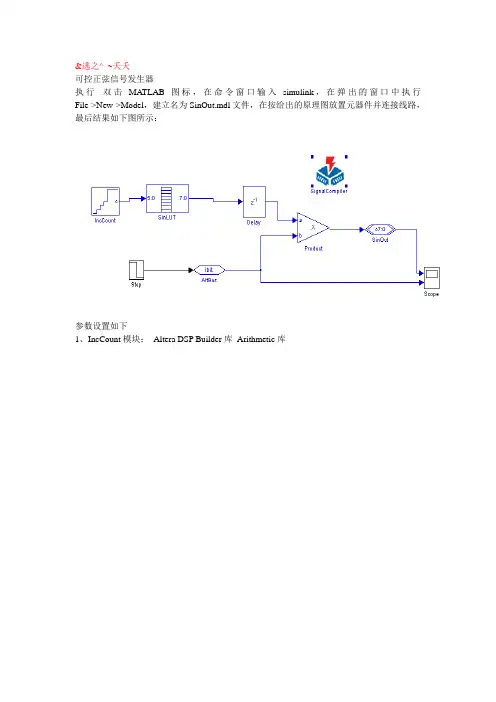
&逃之^_~夭夭可控正弦信号发生器执行双击MA TLAB图标,在命令窗口输入simulink,在弹出的窗口中执行File->New->Model,建立名为SinOut.mdl文件,在按给出的原理图放置元器件并连接线路,最后结果如下图所示:参数设置如下1、IncCount模块:Altera DSP Builder库Arithmetic库改为2、SinLUT模块:Altera DSP Builder库Gate&Control库改为3、Delay模块:Altera DSP Builder库Storagel库改为5、Product模块:Altera DSP Builder库Arithmetic库将改为5、SinOut模块:Altera DSP Builder库I/O&Bus库、改为6、AltBus模块:Altera DSP Builder库I/O&Bus库改为7、Step模块:Simulink库Source库改为Scope中将端口设为两个双击进行分析,分析完成后,打开Quartus II软件,打开分析转换后的Quartus文件,进行编译和仿真,根据出现的提示信息将iSinOuti改为SinOut并将该文件另存为SinOut.vwf,执行Assignments—Device单击simulator setting,在simulation input中选择SinOut.vwf,单击OK即可,再编译仿真Assignment –assignment editor,引脚锁定Tools—programmer 下载执行File->New->SignaiTap II,在中间区域的左边点击鼠标右键添加节点SinOut,在右侧的区域进行如下设置采用模式5,单击采样,使用嵌入式逻辑分析仪看到的结果如下图所示。

信号发生器的MATLAB仿真[摘要]本论文以课题“信号发生器的MATLAB仿真”为背景展开,介绍了MATLAB仿真技术的发展和信号发生器的现状,结合线性调制系统的应用背景设计了一种结构简便、性能优良的线性调制信号发生器,全面的实现信号发生器的功能要求。
本论文主要研究内容包括:1.研究了信号发生器的现状,MATLAB仿真技术的发展及现状,介绍了用MATLAB进行仿真的实用性及可靠性。
2.研究了常规调制信号ASK信号、FSK信号和PSK等有关理论,为信号生成打下基础。
3.以线性调制为例研究了MATLAB仿真的三种方法,比较了其各自的优缺点,同时选定以Simulink进行系统的仿真。
4.用Simulink进行线性调制系统的模拟,完成软件设计的实现,对系统进行调试,使系统达到指标需求。
关键词:信号发生器;线性调制系统;MATLAB仿真;simulink[ABSTRACT]The paper based on the Project “MATLAB simulation of signal generator”, MATLAB simulation technology and the development situation of the signal generator is introduced. Combined with linear modulation system application background designs a simple structure and good performanced linear modulation signal generator. It realize the comprehensive function signal generator.This thesis mainly research contents include:First, research the status of the signal generator and development and the status quo of MATLAB simulation technology. It also introduced the practicability and reliability of MATLAB simulation .Second, study the conventional modulation signal FSK signal and itinerary signal, PSK theories,it layed the foundation for the signal generation.Third, use the example of linear modulation to study three methods of MATLAB simulation, compare their advantages and disadvantages, and decided to use Simulink conduct simulation.Four, using Simulink simulate linear modulation system simulation, realize of the software design, and testing system,finally, make system index demand.Key word :Signal generator; Linearity modulation system; MATLAB Simulation; simulink目录摘要 (1)ABSTRACT (2)目录 (3)第一章绪论 (1)1.1论文的立题背景及研究意义 (1)1.2MATLAB仿真技术的发展及现状 (1)1.3信号发生器的发展及现状 (3)1.4论文的主要研究内容 (4)第二章信号发生器的理论部分 (5)2.1信号发生器分类简介 (5)2.2常规信号 (7)2.3本章小结 (10)第三章MATLAB的三种仿真办法 (11)3.1仿真基础原理 (11)3.2三种仿真方法的简单实现 (12)3.3基于Matlab 7.0的三种仿真方法比较 (15)3.4本章小结 (15)第四章信号发生器的MATLAB仿真实现 (16)4.1常规信号的Matlab仿真实现 (16)4.2线性调制系统Matlab仿真实现 (18)4.3AM信号发生的Simulink仿真实现 (20)4.4本章小结 (23)结束语 (24)致谢 (25)参考文献 (26)第一章绪论1.1 论文的立题背景及研究意义在现代声纳、雷达等通信系统测试与仿真中都需要高精度的任意的波形信号,任意波形信号的重构技术也是声学和语音信号合成等应用领域中的关键技术之一。
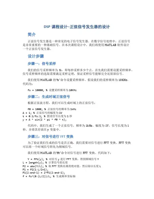
DSP课程设计–正弦信号发生器的设计简介正弦信号发生器是一种常见的电子信号发生器。
在数字信号处理中,正弦信号是非常重要的一种基础信号。
在本次课程设计中,我们将使用MATLAB软件设计一个正弦信号发生器。
设计步骤步骤一:信号采样我们的信号采样频率为fs,即每秒采样多少个点。
首先我们需要设置采样频率。
信号采样频率的选取需要满足采样定理,保证采样信号能够完全还原原信号。
我们使用MATLAB的“fs”命令设置采样频率。
假设我们的采样频率为10KHz,代码为:fs = 10000; % 设置采样频率为10KHz步骤二:生成时域正弦信号根据正弦波方程,我们可以生成时域上的正弦信号:f0 = 1000; % 正弦信号的频率为1kHzA = 1; % 正弦信号的幅度为1Vt = 0:1/fs:1; % 假设信号长度为1秒y = A * sin(2 * pi * f0 * t);代码中,我们生成了一个正弦信号,频率为1kHz,幅度为1V,信号长度为1秒,并将其存放在y变量中。
步骤三:对信号进行FFT变换为了验证我们生成的信号是否正确,我们需要对信号进行FFT变换。
FFT变换可以将一个时域信号转化为频域信号。
我们使用MATLAB的“fft”命令对信号进行FFT变换。
代码如下:Y = fft(y); % 对信号y进行FFT变换,得到频域信号YL = length(y); % 计算信号的长度P2 = abs(Y/L); % 取FFT变换结果的绝对值,然后除以长度LP1 = P2(1:L/2+1);P1(2:end-1) = 2*P1(2:end-1);f = fs*(0:(L/2))/L; % 生成频率坐标轴代码中,我们使用FFT变换对信号y进行变换,并将结果存放在Y变量中。
然后我们根据FFT变换结果,得到频率分量以及对应的幅度分量。
步骤四:绘制频域正弦信号最后,我们使用MATLAB的plot函数绘制频域信号采样结果图。
MatlabGUI程序设计⼊门——信号发⽣器+时域分析背景:学习matlab gui编程⼊门,完成⼀个基于GUIDE的图形化界⾯程序,结合信号⽣成及分析等。
操作步骤:1、新建程序新建⼀个GUIDE程序这⾥选择第⼀个选项,即创建⼀个空⽩的GUIDE模板(下⾯的三个选项为matlab⾃带的3个guide模板,可以尝试使⽤,但是空⽩模板更灵活⼀些)。
创建完成后,将会得到这样⼀个⾯板,这就是进⾏matlab进⾏guide图形化编程界⾯,在这⾥我们可以添加我们需要的各种控件到⾯板中。
可以看到上图中的,左侧有7⾏2列共14个常⽤的控件,添加时直接拖动即可,右侧的带油栅格的⾯板就是完成guide变成后,程序运⾏时的图形化界⾯。
7⾏2列控件分别为:普通按钮滑动条单选按钮复选按钮可编辑⽂本静态⽂本弹出式菜单列表框切换按钮表坐标轴⾯板按钮组ActiveX控件其中常⽤的控件包括:普通按钮、滑动条、可编辑⽂本、静态⽂本、坐标轴等。
2、图形化界⾯编程⾸先可以根据预计⽣成的⾯板的⼤⼩,拉伸编程⾯板。
然后将需要的控件拖拽到编程⾯板中,并进⾏布局。
这⾥可以使⽤上⽅⼯具栏的“对其对象”⼯具,进⾏布局。
如:完成布局后可以双击各个控件,修改其属性,控件的属性⾯板如下:(以滑动条为例)下⾯,对⼏个⽐较重要的属性进⾏介绍:字体属性:滑动条变量取值范围:标注⽂字(String)&标签(Tag):标签是最重要的属性,在代码中对每⼀个控件进⾏操作时,都是以其tag作为索引。
单位(Units)&初始值(Value):单位⼀般会选择charaters(绝对单位)和normalized(相对单位),选择characters则输出值为设定的最⼤最⼩值之间的实际值,选择normalized则输出值为归⼀化后的0~1之间的值。
其他各个控件的属性会有⼀些区别,和各个控件⾃⾝的特性有关,基本可以直接根据各个属性的字⾯意思理解。
完成控件的添加、布局和属性设定后,即可得到⼀个如下的界⾯图:3、m⽂件编程:完成上述图形编程后,点击保存,则会⾃动根据我们的设定,⽣成⼀个m⽂件模板。
基于MATLAB的数字信号发生器设计报告蔡辉机电M201070440摘要:数字信号发生器是基于软硬件实现的一种波形发生仪器。
在工工程实践中需要检测和分析的各种复杂信号均可分解成各简单信号之和,而这些简单信号皆可由数字信号发生器模拟产生,因此它在工程分析和实验教学有着广泛的应用。
MATLAB是一个数据分析和处理功能十分强大的工程实用软件,他的数据采集工具箱为实现数据的输入和输出提供了十分方便的函数和命令,在数字信号处理方面方便实用。
本文介绍了使用MATLAB建立一个简单数字信号发生器的基本流程,并详细叙述了简单波形(正弦波、方波、三角波、锯齿波、白噪声)信号的具体实现方法。
关键字:MATLAB ,数字信号发生器1概述随着计算机软硬件技术的发展,越来越多现实物品的功能能够由计算机实现。
信号发生器原本是模拟电子技术发展的产物,到后来的数字信号发生器也是通过硬件实现的,本文将给出通过计算机软件实现的数字信号发生器。
信号发生器是一种常用的信号源,广泛应用于电子技术实验、自控系统和科学研究等领域。
传统的台式仪器如任意函数发生器等加工工艺复杂、价格高、仪器面板单调、数据存储、处理不方便。
以Matlab和LabVlEW 为代表的软件的出现,轻松地用虚拟仪器技术解决了这些问题。
Matlab 是一个数据分析和处理功能十分强大的工程实用软件,他的数据采集工具箱(data acquisition toolbox )为实现数据的输入和输出提供了十分方便的函数和命令,利用这些函数和命令可以很容易地实现对外部物理世界的信号输出和输入。
根据声卡输出信号的原理,采用Matlab 软件编程,可以方便地输出所需要的正弦波、三角波、方波等多种信号,有效地实现信号发生器的基本功能。
2 设计原理要设计的数字信号有正弦信号、方波信号、三角波、锯齿波、白噪声、脉冲信号。
其中,前五种波形都可以利用MATLAB 提供的函数实现,并根据输入的幅值、相位、频率等信息进行调整。