摩托罗拉V70主板信号流程图
- 格式:pdf
- 大小:164.29 KB
- 文档页数:2

手机原理图分析一、手机基本电路框图:二、基带CPU(MT6226)内部框图:1、组成部分:z DSP:主要完成对语音信号的编解码、信道编码、加密、交织处理等;z ARM7:主要是对外部Memory接口、用户接口(LCD、键盘、触摸等)、语音接口、射频接口、电源管理等的命令控制,使各部分协调工作。
2、基带部分语音编码过程(DSP):GSM标准规定时隙宽为0.577ms,8个时隙为一帧,帧周期为0.577×8=4.615ms。
因此,用示波器观测GSM移动电话机收发信息,会看到周期为4.615ms、宽0.577ms的突发脉冲。
基带部分电路包括信道编/译码、加密/解密、TDMA帧形成/信道分离及基准时钟电路,它还包括话音/译码、码速适配器等电路。
来自送话器的话音信号经过8kHz抽样及A/D转换,变成13bit均匀量化的104kbit/s数据流,再由话音编码器进行RPE-LTP编码。
编码输入为每20ms一段,经话音编码压缩后变为260bit,其中LPC-LTP为72bit,RPE为188bit。
话音编码后的信号速率为13kbit/s。
同时话音编码器还提供话音活性检测(vAD)功能,即当有话音时,其SP信号为1;当无话音传输时,将SP示为0(即SID帧)。
13kbit/s 话音信号进入信道编码器进行编码。
对于话音信号的每20ms 段,信道编码器首先对话音信号中最重要的Ia 类50bit 进行分组编码(CRC 校验),产生3bit 校验位,再与132bit 的Ib 类比特组成185bit ,再加上4个尾比特“0”,组合为189bit ,这189bit 再进入1/2速率卷积码编码器,该编码限制长度为5,最后产生出378bit 。
这378bit 再与话音信号中对无线信道最不敏感的II 类78bit 组成最终的456bit 组。
同样,对于信令信号,由控制器产生并送给信道编码器,首先按FIRE(法尔)码进行分组编码(称为块编码),然后再进入1/2卷积编码,最后形成456bit 组。
目录一、手机工作流程示意图(Infineon平台、Broadcom平台、MTK平台)二、射频部分讲解三、逻辑部分讲解四、电源部分讲解五、电性能部分讲解手机工作流程示意图一、射频部分讲解1、 接收电路由天线接收到的高频信号送到PR 接口,再送往射频转换开关,此时具有GSM 和DCS 两种工作状态: 频段切换的控制信号VC1、VC2 1 0 处于GSM 发射状态 0 0处于GSM 、DCS 接收状态 0 DCS 发射状态 再经射频转换开关虑波后的一路900MHZ 的接收信号经高频虑波器虑波送到中频IC ,另一路1800MHZ 的接收信号经高频虑波器虑波送到中频IC ;中频IC 对虑波后接收信号在内部进行低噪声放大,然后和接收本振送来的接收信号进行混频,产生360MHZ 的中频信号送到中频虑波器进行虑波,虑波后的中频信号送往中频IC 再进行二次混频,最终产生四路接收I/O 信号送往BGA ;在BGA 内部进行A/D 转换以及信号外理,然后再经过在D/A 转换面语音信号送往LCD 、听简等。
2、 发射电路 语音信号从MIC 输入,BGA 将语音信号转换成电流信号,在BGA 内部进行A/D 转换和数字信号处理,然后再D/A 转换调制成发射信号的I/O 信号,送到中频IC 进行调制;由中频IC 内部进行变频产生424MHZ 的发射信号,再和发射本振进行混频、虑波产生发射信号,然后发射本振振荡产生所需的GSM 、DCS 的发射频率信号送到功率放大IC ;当手机收到基站发出的功率级别要求,在BGA控制下从功率表中调出相应的功率级别数据,经过D/A转换成标准功率控制电平与实际发射的功率值比较,产生误差电压去调节激励放大电路、功放增益,将放大后的信号送到射频转换开关进行GSM900和DCS1800的频段切换,最终送往天线进行发射。
3、线路流程接收通路:天线信号射频测试点射频转换开关高频虑波器(一路GSM900信号;一路DCS1800信号)中频IC接收本振中频虑波器BGA发射通路:MIC受话BGA 中频IC发射本振功率放大IC射频转换开关射频测试点天线信号4、维修实例Infineon平台:Broadcom平台:不入软件位ABORT:A、电流为0的情况:1、32KHZ是否正常工作;2、U4外围电阻R8、R15、C73、C74的阻值是否正常;3、开机键U4#43脚BGAB、电流过小的情况:1、13MHZ是否正常工作;2、13MHZ U17BGA3、U4外围电阻R40、R39的阻值是否正常;4、U19的虚焊、不良问题引起的;C、电流正常,但不入软件:1、U1、U21、U4不良问题引起的;2、U21外围电阻R40、R39的阻值是否正常;3、尾插J4U1之间的物理通路是否导通;3、U19、FL4、FL5的虚焊、不良问题引起的;D、电流过大的情况:1、U1、U21、U4、U14不良问题引起的;2、U16、U18的短接、不良问题引起的;3、U19的短接、不良问题引起的;4、U4Q3;5、U17Q1;6、U1外围电阻的短接问题引起的;E、failed的情况:1、尾插U1的物理通路是否导通;2、U21U1的物理通路是否导通;3、13MHZ不良问题引起的;F、能入软件,但不开机的情况:1、U4U21的供电线路是否导通;(串口线路:尾插U1,尾插的7、8脚对地阻值大约在1.4MHZ左右为正常,)校准位:A、ABORT1、U21不良问题引起的;(能入软件,但校准不过)2、U4不良问题引起的;(测试机柜的电流过小的情况)3、U1不良问题引起的;(测试机柜的电流正常的情况)4、U45、U41、U6不良问题引起的;(测试机柜的电流过大的情况)5、尾插U1,尾插的7、8脚对地阻值大约在1.4MHZ左右为正常;6、U19短路、不良问题引起的;7、32KHZ是否正常工作,R11的阻值大约在1.4MHZ左右为正常;8、13MHZ U17BGA;9、FL4、FL5不良问题引起的;(能开机、但校准不过)10、CON1不良问题引起的;12、充电线路Q29、Q28、Q23不良问题引起的;13、U17不良问题引起的;B、10041、C、4002(手机电流过大)1、U4、U17、U14、U13不良问题引起的;2、U4R1、R2BGA;3、BGA外围的电阻、电容是否短接问题引起的,以及相关的电阻、电容是否阻值正常;4、U6、U18短接、不良问题引起的;D、50021(GSM的TX POWER校准不合格)1、从开机电流的大小(不低于50~60mA),判断手机能不能上网;2、若静态下电流大于100 mA,U1、U4、U17、U14不良问题引起的;3、U4U17,U4U14的供电问题;4、U1不良问题引起的;(功率控制器)5、JI不良问题引起的;(用射频头接触J1,测量J1的阻值大约在0.6~0.7M左右为正常)6、U13不良问题引起的;7、13MHZ、U17不良问题引起的;8、U16、U18不良问题引起的;9、U4不良问题引起的;10、U21不良问题引起的;(软件问题)E、50039(DCS的TX POWER校准不合格)1、U13 U14、U14 U1的DCS线路;2、4 U14的供电问题;3、J1不良问题引起的;(用射频头接触J1,测量J1的阻值大约在0.6~0.7M左右为正常)4、U13 FL1 U17;5、U16、U18不良问题引起的;(测量其对地阻值是否正常)6、DISP1短路引起的;7、U1、U4不良问题引起的;8、若转换DCS掉电,则TX VCO、U14等相关器件引起的,以及外围电路是否焊接良好;F、5002411、5002413、5002431(GSM频率较准检查)1、U1 U17 U16、U18 U14不良问题引起的;(5002411)2、U4 13MHZ U17不良问题引起的;(5002413)G、5002531(DCS的频率较准检查)1、U17 U16不良问题引起的;联发平台:不入软件位:1、U200不良,U100 U200的物理通路是否导通;(电流正常,但不入软件)2、U506、DISP1插槽短路、不良引起的;(电流有短路现象)3、U207、U208、U201贴反、短路、不良引起的;(开机电流大约在200mA左右)5、U100的外围电路以及相关的电阻、电容是否阻值正常;6、U300 C310 BGA的供电线路;7、U300 L501 IC的供电线路;8、开机键U306 U300的供电线路;(U306的引脚1对地电阻170K欧姆左右)9、U504不良;(无26M基准时钟信号会引起不开机)(串口线路:尾插、U208 U100)校准位A、C1.3(ADC的校准):1、RN301不良引起的;(RN301右边的4个引脚的对地电阻正常值为50k欧姆左右)2、U100不良引起的;B、C1.4(AFC的测量、校准):1、U504 U506,X100不良问题引起的;(能呼叫网络的情况)1、U100不良;(开机时电流静止不动)2、U506不良;(开机时电流正常跳动)C、C3.5、C5.5 (GSM、DCS中间信道发射功率):1、U502虚焊问题引起的;2、U506不良;(能呼叫网络、掉线的情况)3、U502不良;(能呼叫网络、功率过大的情况)D、C4.3、C6.3(GSM、DCS接受功率校准):1、U502虚焊问题引起的;2、U506不良;(能呼叫网络、功率过低的情况)3、U510 R330 U507,R330不良;(开机电流达不到呼叫网络的要求)二、逻辑部分讲解A、这部分电路要正常工作需要满足以下条件:1、13MHZ晶振信号要正常工作,2、电源IC的供电电压要正常工作,3、程序存储器FLASH和基带IC的物理通路能正常工作,4、相关的供电线路能正常工作(没有短路现象和电流异常现象)。

Motorola 摩托罗拉无线交换机RFS7000/WS5100v3.x(以下配置以RFS7000为例)快速配置目录快速配置指南 (3)1 特别注意 (3)2 AC配置前准备工作 (3)3 AC基础配置 (4)1.1 初次登录 (4)***CLI 命令行指令概述 (7)1.2 VLAN及IP地址配置 (9)1.3 WLAN设置(含HOTSPOT配置) (12)1.4 AP300设置及状态检查 (18)1.5 接入终端状态检查 (22)1.6 配置DHCP服务 (23)1.7 配置静态路由 (25)1.8 配置冗余热备 (27)4 密码恢复 (29)5 版本升级 (31)CLI命令行说明 (34)参考拓扑 (38)设备维护指南 (39)1 日例行工作 (39)1.1 机房温湿度检查。
(39)1.2 电源设备检查。
(39)1.3 设备供电情况检查(白班、夜班各一次)。
(39)1.4 设备状态检查(白班、夜班各一次)。
(39)1.5 设备告警信息(白班、夜班各一次) (42)1.6 AP在线检查(白班、夜班各一次) (43)1.7 检查各接入点登录网络的用户状态 (44)1.8 检查DHCP SERVER服务器运行状态(3层部署时需要) (44)2 周例行工作 (45)2.1 故障统计汇总(每周一)。
(45)2.2 备份电子版维护作业计划执行记录(每周五)。
(45)3 月例行工作 (45)3.1 WLAN MOTO设备配置文件备份。
(45)3.2 传输资料的检查核对 (45)3.3 AP终端运行情况检查 (45)3.4 标签检查 (45)3.5 进行系统设备巡检 (45)快速配置指南1 特别注意关机必须要先用halt命令停止系统。
2 AC配置前准备工作Hardware需求:AC及安装附件一套标准220V交流电源线一根Console cable一条台式机或笔记本电脑一台,配有以太网端口(100Mbps/1000Mbps以太网网卡)RJ45交叉网线1条(568B and 568A)Software需求:超级终端软件标准WEB浏览器,IE and etc,.Java Environment,Version 1.5 or laterMotorola AC的参数配置可以通过两种方式(LAN和CONSOLE)进行配置。

1.AO~A15 地址总线2.。
A①模拟②安培3。
AB(AddressBus)地址总线4.ADC(A/D)模拟到数字的转换5.AFC自动频率控制6.AFMS来音频信号7.AFPCB音频电路板8。
AGC自动增益控制9.AGND模拟地10.ALARM告警11.ALERT振铃12.ANODE阳极13。
ANT天线14。
ANTSW天线开关15.AOP VCC模拟基带放大器供电16.APC 自动功率控制17。
ATMS到移动台音频信号18。
AUDIO音频19。
AUTO 自动AUX辅助20。
AVCC音频供电、辅助供电1.B. 三极管基极2。
B+内部工作电压3.BACKLIGHT背光4.BASE基极5。
BASE BAND基带(信号) 6。
BATT 电池7。
BATTERY 电池8.BCD 二~十进制数9。
BLUE蓝色10。
BIC总线接口芯片(摩托罗拉手机)11。
Bit比特12。
BOOT屏蔽罩13。
BOX箱子、盒子14.BRIGHT发光15。
BDF带通滤波16。
BGA 球栅阵列封装技术17。
BS 基站18.BUS振铃19。
BUS总线20。
BUSY忙21。
BUZZER(Buz)振铃1.C三极管集电极2。
CAPACITY电容3。
CAED卡4。
CB 控制总线5.CDMA码分多址6.CELL小区7.CELLULAR 蜂窝8。
Check检查(校验)9.CHAGCER 充电器10。
CIRCCITY 整机11。
CLOCK时钟12.CMOS 互补重金氧化物半导体13.CLONE 复制、克隆14.CODE 代码15.CONNECTOR 连接器16.CONTACT SERVICER 联系服务商17。
CONTROL 控制18。
COUPLING 耦合19。
COVER 覆盖20.CPU 中央处理器21。
CPU ON OFF中央处理开/关22.CRYSTAL 晶体23。
CS FLASH 闪速存储器片选24。
CS RAM随机存储片选25.CS ROM只读存储片选26。
新手篇—图解手机维修入门与精通(下)410.3.2索尼爱立信手机液晶屏显示电路故障检修过程故障现象描述索尼爱立信K7000开机后键盘指示灯亮,拨打电话正常,但液晶显示屏背光灯不亮。
故障分析指导索尼爱立信K7000液晶屏显示电路也是通过接口插座与主电路板连接,如图10-9所示。
由微处理器D2220输出的数据信号经液晶屏屏线送到液晶屏显示电路中,经过处理后,数据信息由显示屏显示出来。
如图10-10所示为索尼爱立信K7000手机液晶屏显示电路。
故障检修指导液晶屏背光不亮,重点检查液晶屏显示灯电路中的显示灯芯片及周围元器件是否损坏。
(1)首先检查液晶屏屏线接口是否连接良好,如图10-11所示为液晶屏显示电路插座。
液晶屏显示电路中的元器件有无脱焊、虚焊现象,经过检查没有发现这些现象。
(2)接着检测电路中的电容元器件,将万用表量程选择“R×10”挡,红、黑表笔分别连接电容两端,测的阻值为130Ω,正常,检测方法如图10-12所示。
(3)经过检查电容性能良好,再仔细检查液晶屏显示电路发现,排线上有一个插件松动,如图10-13所示为背光灯连接插件。
将插件引线取出,重新连接。
开机后,故障排除。
10.3.3摩托罗拉手机液晶屏显示电路故障检修过程故障现象描述摩托罗拉V500手机开机正常,手机主显示屏显示正常,但副显示屏无显示。
故障分析指导摩托罗拉V500手机液晶屏显示电路是通过液晶屏屏线与主电路板连接,如图10-14所示。
由系统控制/数据处理芯片U800输出的数据信号送到屏线接口插座中,再通过屏线及液晶屏显示电路的插座送到电路中,经过处理后,数据信息最终由显示屏显示出来。
如图10-15所示为液晶屏显示电路上的液晶屏屏线及连接接口,U800输出的数据信号只有通过该接口才能送到副显示屏电路中。
摩托罗拉V500手机还设置有副显示屏,它是通过接口插座与主显示屏电路板相连接,如图10-16所示。
故障检修指导摩托罗拉V500手机主显示屏显示信息正常,而副显示屏无显示,重点可检查副显示屏电路。
主板开机电路的构成及工作原理图核心提示:一、开机电路的构成及工作原理PWR:主机上的电源开关原理:在按下PWR开关之前,主机上只有紫线和绿有电,紫线为5VSB(待机电压)。
南桥或I/O内部集成了开机触发电路,所有的开机触发电路都是舜间低电平有效(除83627系列I/O),按下PWR开关后会产生舜间的一、开机电路的构成及工作原理PWR:主机上的电源开关原理:在按下PWR开关之前,主机上只有紫线和绿有电,紫线为5VSB(待机电压)。
南桥或I/O内部集成了开机触发电路,所有的开机触发电路都是舜间低电平有效(除83627系列I/O),按下PWR开关后会产生舜间的低电平,南桥开机触发电路工作后发输出迟续的高电平,I/O内部的开机触发电路工作后输出迟续的低电平。
一些厂家的主板上集成了自己的开机复位芯片,不通过南桥或I/O开机,原理是一样的。
二、开关的三种方式常见主板开机电路图一、开机线路图1、VIA大多由南桥开机,有83977EFI/O的由I/O开机2、inter主板较,83627高进高出,8702、8712低进低出3、SIS开机电路4、VIA多,370、462主板常见故障现象:无法软关机,开机不稳定时好时坏,多为门电路坏二、I/O开机图1、132门电路容易损坏2、83627I/O中第67脚有3.3V高电平(点PWR不机,且67脚有3.3V电压为I/O坏,少数为南桥坏)3、83627第67脚为0V,查南桥待机电压,拆下I/O测4、83627第67脚为0V-1V,I/O坏5、83627I/O损坏的故障现象:不开机、能开机不能关机、复位灯常亮第一种两针短接后为低电平,第二种两短接后都为低电平,第三种两针短接后都为高电平三、开机电路检修流程1.查PWR开关处是否有3.3V左右的高电平。
(查开关到紫线之间的线路)2.按下PWR开关时测量是否有瞬间低电平触发南桥或I/O。
3.查绿线到南桥或I/O之间的线路。
故障现象:开机后通下电,马上断电按PWR无反应,这种现象称为电源保护,多为黄、红线短路,用断路法逐个断开与短路电压相关的元件。
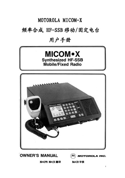
Motorola® Saber™ Radio Service Software User’s Guide业余无线电中文计划注意:·本说明书参照Motorola 68P81062C95-F文档翻译,内容有删改。
·本说明书针对的RSS(Radio Service Software)版本为R07.01.00,该版本软件已经可以支持高时钟频率的计算机,并拥有最全面的功能,推荐您采用。
·译者英语和无线电知识水平有限,难免有错误和不足,敬请各位老师指正!版权声明:The Motorola equipment described in this manual may includecopyrighted Motorola computer programs stored in semiconductor memories or other media. Laws in the United States and other countries preserve for Motorola certain exclusive rights for copyrighted computer programs, including the exclusive right to copy or reproduce in any form the copyrighted computer program. Accordingly, any copyrighted Motorola computer programs contained in the Motorola equipment described in this manual may not be copied or reproduced in any manner without the express permission of Motorola. Furthermore, the purchase of Motorola equipment shall not be deemed to grant either directly or by implication, estoppel, or otherwise, any license under the copyrights, patents or patent applications of Motorola, except for the normal nonexclusive, royalty free license to use that arises by operation of law in the sales of a product.版本:Ver. 0.1(02/12/2007)本项目参与者:暂无请您加入“业余无线电中文计划”,为中国业余无线电发展献出一份力量!第一部分 SERVICE: alignment, service aids, board replacement一、Align Radio Parameters注意:当您修改了本菜单中的任何设置后,您需要为电台重新编程(Reprogram Radio),才能使改动生效。
ThinkTop V50and V70are designed for use in the dairy,food,beverage,and biopharma industries.Benefits•Auto setup•Automatic valve recognition•Automatic selection of tolerance band•Fast,Live and Flex Setup•360-degree LED indication•Burst seat clean•Exchangeable(threaded)air-fittings•Interchangeable with ThinkTop classicsWorking principlesThe control unit offers a single sensor solution for diaphragm,butterfly, single-seat and mixproof valves and it can befitted with up to three solenoid valves.ThinkTop converts the electrical PLC output signals into mechanical energy to energise,or de-energise,the air-operated valve,using the physical sensor target mounted on the valve stem.Installation with Auto Setup or Live Setup is intuitive and fast.To initiate Auto Setup,simply press the“SELECT”button and then the“ENTER”button to begin the setup sequence.The ThinkTop automatically recognizes the type of valve and completes the programming sequence fast and efficiently.Alternatively,the ThinkTop can be set up,without dismantling the control head,using the built-in Live Setup feature for remote-configuration.CertificatesDimensions(mm)Figure1.ThinkTop V50Figure2.ThinkTop V70mm Inch mm Inch A123 4.84A164 6.45 B105 4.13B105 4.13 C2007.87C2509.84 D150 5.91D170 6.69 TECHNICAL DATAMaterialPlastic parts Nylon PA12Steel parts 1.4301/304Airfittings Nickel plated/Nylon PA6Gaskets Nitril/NBREnvironmentWorking temperature-10°C to+60°CProtection class(IP)IP66,IP67and IP69KProtection class(NEMA)4,4X and6PHazardous area ATEX and IECex in preperationControl boardCommunication See interfaces sectionSensor accuracy±0,1mmV50–Valve stem length Below<65mmV70–Valve stem length Above>65mmMean Time To Failure(MTTF)224yearsApprovals UL/CSA Certificate:E174191Solenoid valveSupply voltage24VDC±10%Nominal power0,3WAir supply300-800kPa(3-8bar)Type of solenoids3/2-ways or5/2-wayNumber of solenoids0-3Manual hold override YesAir quality Class3,3,3acc.DIN ISO8573-1B10data5Million cyclesRecommendation Operate once a month to prevent dry-outNote:Throughout this leaflet,SV is used as an abbreviation for a soleniod valveAirfittingThrottle function air inlet/outlet0-100%Threaded airfitting G1/86mm(Rim blue)or1/4"(Rim Grey)Elbow push-infittings6mm(Rim blue)or1/4"(Rim Grey)Cable connectionMain cable gland entry Digital M16(ø4-ø10mm)(0,16"-0,39")Main cable gland entry AS-I M16(ø2-ø7mm)(0,08"-0,28")Seat lift sensor cable gland entry M12(ø3,5-ø7mm)(0,14"-0,28")Max wire diameter0.75mm2(AWG20)VibrationVibration18Hz-1kHz@7,54g RMSShock100gHumidityConstant humidity+40°C,21days,93%R.H.Cyclic humidity-25°C/+55°C,12cycles(working)93%R.H.Accessories by functionalityUpper seat lift surveillance KitValve speed reduction0-100%Valve closing speed increase Quick air exhaust,ø6mmSolenoid valve protection Supply airfilter1/8”,avoid clogging of solenoid valvesOPERATIONAL DATALED indicationThinkTop features a360-degree light guide.Whenthe sensor target is within the respective setupposition band,the corresponding colour lights up.De-energised Energised Energised EnergisedThinkTop ModeFactory setting Greenflashing Whiteflashing Blueflashing Yellowflashing OffOperation Green White Blue Yellow OffNot OK Green/redflashing White/redflashing Blue/redflashing Yellow/redflashing RedflashingAuto setupAuto Setup is a rule-based function.If one of these rules are not present,Flex Setup must be used.By default,ThinkTop V50and V70uses the de-Energised/Energised paradigm for valve positions feedback.Parameter Auto Setup/Live Setup Flex Setup(retrofit mode) Status feedback(OK or error)Valve state(Fail safe signal)Status errorSeat cleaning function Enabled DisabledValve operation monitor Enabled DisabledExt.sensor operation monitor Enabled DisabledInterlock Enabled DisabledOutput(AS-i master input)Special SpecialExternal sensor masking Enabled DisabledValve compatibility chartUse Anytime configurator for correct selection of V50and V70on different valve size and typesCommon applications (Auto/Live Setup)Special applications(Flex Setup)IncompatiblevalvesThinkTop V50Single Seat valves Small Single Seat valve Butterfly valves Diaphragm valvesBall valvesShutter valvesDouble seat valves Double seal valveThinkTop V70In addition to the ThinkTop V50valvesDouble seat valvesDouble seal valveLong stroke single seat valvesDiaphragm valvesAir/Air valves•ThinkTop classic retrofit modeor alternative setup with norestrictions•Feedback structure such as theopen/closed valve feedback•All SSV(1/2"-4")NO,shut off,maintainable,need to be setupas a rotary valve•Application with no solenoidvalve,feedback indication only•One control unit to controlmultiple valves•SMP-BC where using2solenoidvalve to operate main valveand pilot leak-detect valvesindependently•Valves without raising stem andmushrooms•Regulating valves•Safety valves•Sample valves•SMP-EC•700series•Other valve brands3.9.3Overview of connectors and portsa:Solenoid valve connectorb:Indication lampc:Main terminalsba:Diagnostic Portb:Seat lift sensor terminalBurst clean modeBurst seat clean mode is available for ThinkTop V70and can be enabled when a ThinkTop V70with 2or 3solenoid valves is setup successfully using Auto Setup.The burst seat clean mode is enabled or disabled via the ThinkTop V70control board.Press "SELECT"(4times)until LED no 4flashes,and then press ’ENTER"to enable or disable.This option is also available as an adjustable IO-Link parameter.The burst seat clean option is from factory disabled by default.However,if it is enabled and there is a manual reset to factory default,the burst seat clean option is disabled.a dc b ee e2066-0032a:Input (from PLC)b:Positionc:Solenoidvalve outputd:Output minimum 2sec.(both visual and electrical)e:Position reachedWhen the PLC input signal for either upper or lower seat push (Usl,Lsp)goes high,the respective solenoid valve is Energised.As soon as the sensor target reaches the prede fined energised valve position,the solenoid valve is automatically de-energised by the ThinkTop V70.A two-second electrical and visual feedback (t)is provided as a handshake for successful completion of a burst seat pulse.The PLC input duration must be at least 500ms (d).If ThinkTop V70is set up using Auto Setup without the upper seat lift sensor,the function uses the stored setup stroke time for “Lower seat push ”plus some extra time for when the solenoid valve is deactivated.Water consumption graphThinkTop V70CIP liquid consumption during Burst seat clean on different Mixproof valves,provided with 6bar air pressure:Figure 3.Unique Mixproof valve /Unique CP-3Mixproof valve 1.5”DN 40and 2”DN50Nominal liter/Burst clean [1]00.20.40.60.81.01.21.41.61.80.511.522.53000CIP liquid pressure [bar]Figure 4.Unique Mixproof valve /Unique CP-3Mixproof valve 2.5”DN65and 3”DN80Nominal liter/Burst clean [1]000000.51 1.52 2.530.20.40.60.81.01.21.41.61.8CIP liquid pressure [bar]Figure 5.Unique Mixproof valve /Unique CP-3Mixproof valve 4”DN100Nominal liter/Burst clean [1]000000.511.522.530.20.40.60.81.01.21.41.61.8CIP liquid pressure [bar]Lower Seat Push Upper Seat LiftValve state–Fail safe signalThe following table gives an overview of behaviour per Error condition where the valve state signal goes low.Further description of the various Error conditions can be found in the ThinkTop Instruction Manual,section5,2.Valve state is a decentralized functionality,available for all ThinkTop variants and a feature that can be used for monitoring process issues or to ease and simplify the PLC programming of a valve surveillance.ThinkTop Digital Valve state ThinkTop AS-InterfaceNot AvailableThinkTop IO-LinkValve stateError Code#Error description FAIL SAFE SIGNALbehaviourDE-ENERGIZED SIGNALbehaviourFAIL SAFE SIGNALbehaviour15Key lock active na na na16Sensor target missing Drops low Drops low Drops low 17Setup missing peripherals na na na18Pneumatic part issue na na na19Seat lift sensor issue Drops low Drops low Drops low 20Position not reached Drops low Drops low Drops low 21Unexpected valve movement Drops low Drops low Drops low 22Seat-lift sensor missing Drops low Drops low Drops low 23Solenoid valve1missing Drops low No effect Drops low 24Solenoid valve2missing Drops low No effect Drops low 25Solenoid valve3missing Drops low No effect Drops low 26Interlock warning Drops low No effect Drops low 27Hardware fault Drops low No effect Drops low 28Setup aborted na na na29Blocked button Drops low No effect Drops low 30Voltage Low Drops low No effect Drops low 31Safety stop Drops low Drops low Drops lowDefault bitmappingThe default settings apply to both Digital,AS-Interface and IO-LinkThinkTop V50truth signal table:default factory settingDE-EN(I0) close MAIN(I1)openValve state(Fail safe signal)DE-EN(No active SV)101 MAIN SV1active(O1)011ThinkTop V70truth signal table:default factory settingDE-EN(I0) all closed MAIN(I1)openUSL(I2)openLSP(I3)openValve state(Fail safe signal)DE-EN(No active SV)Both seats closedLower seat in closed positionUpper seat in closed position10001MAIN SV1active(O1)Lower seat in open valve positionUpper seat not closed01001 USL SV2active(O2)Upper seat not closeLower seat in closed position00101 LSP SV3active(O3)Lower seat in seat push positionUpper seat in closed position00011pliance optionApplies to both Digital Interface and AS-Interface,and ThinkTop V70variants only.The pliance option refers to a bitmapping interface used in the USA on Mixproof valves,fitted with3solenoid valves.This U.S.A.bitmapping can be enabled after or before auto setup.U.S.regulations require independent closed position feedback signals for upper seat lift and lower seat push in a Mixproof valve application.The U.S.A.bitmapping are enabled or disabled on the ThinkTop V70control board.Press"SELECT"(5times)until LED no8flashes,and then press’ENTER"to enable or disable.This option is also available as an adjustable IO-Link parameter.The pliance option is from factory disabled by default.However,if it is enabled and there is a manual reset to factory default,the U.S.A. compliance option remains enabled.U.S.A.bitmappingThe information in the table is based on the following setup:•ThinkTop V70with3solenoid valves•IFT series seat lift sensor of the type NO or NC•Mixproof valve with both seats installed(balanced or unbalanced upper plug)•Any combination of above valve type and sensor typeDE-EN(I0) Both closed MAIN(I1)openUSL(I2)closedLSP(I3)closedValve state(Fail safe signal)DE-EN(No active SV)Both seats closedLower seat in closed positionUpper seat in closed position10111MAIN SV1active(O1)Lower seat in open valve positionUpper seat not closed01001 USL SV2active(O2)Upper seat not closedLower seat in closed position00011 LSP SV3active(O3)Lower seat in seat push positionUpper seat in closed position00101Digital interface ThinkTop Digital24V DCDevice name ThinkTop V5024V Digital ThinkTop V7024V DigitalVoltage supply•24VDC±10%;according to EN61131-2Protection •Reverse polarity(24VDC±10%);EN61131-2•Voltage interruption and brown-out;EN61131•Short circuit;EN61131Current consumption•Nominal30mA(Idle)Outputs to PLC•Max100mA(solenoid valve and seat lift sensor active)PLC input card•Max rated24V/100AUL supply•Class2according to cULusVoltage drop•Typical3V at50mATerminal type •Spring force push-in technology•Supports nominal wire cross-section between1.0mm2[17AWG]and0.30mm2[22AWG]•Supports wire and ferrules for wire cross-section of0.75mm2[18AWG]with pin length12mmElectrical connectionsThinkTop V50Terminals Control board Colour code wires124V BN(brown)2GND BU(blue)3out:Valve state WH(white)4out:DE-EN BK(black)5out:EN.Main valve GY(grey)6in:SV1.Main valve PK(pink)ThinkTop V70Terminals Control board Colour code wires124V BN(brown)2GND BU(blue)3out:Valve state WH(white)4out:DE-EN BK(black)5out:EN.Main valve GY(grey)6out:USL.Upper seat lift PK(pink)7out:LSP.Lower seat push VT(violet)8in SV1.Main valve YE(yellow)9in SV2.Upper seat lift GN(green)10in SV3.Lower seat push RD(red)Seat lift sensorE1L+BN(brown)E2GND BU(blue)E3Signal BK and WH(black and white)M12option(8-pin A-coded plug)Pin numbers and terminal numbers are alignedM12Chassis plug connector Control boardTerminal numbersM12pin numberswire colors1:24V Pin1:BN(brown) 2:GND Pin3:BU(blue)3:out:Valve state Pin2:WH(white)4:out:DE-EN Pin4:BK(black)5:out:EN.Main valve Pin5:GY(grey)6:in SV1.Main valve Pin6:PK(pink)7:nc-8:nc-ThinkTop V70M12option(12-pin A-coded plug)Pin numbers and terminal numbers are alignedM12Chassis plug connector Control boardTerminal numbersM12pin numberswire colors1:24V Pin1:BN(brown) 2:GND Pin3:BU(blue) 3:out:Valve state Pin2:WH(white) 4:out:DE-EN Pin4:BK(black)5:out:EN.Main valve Pin5:GY(grey) 6:out:USL Upper seat lift Pin6:PK(pink) 7:out:LSP Lower seat push Pin7:VT(violet) 8:in SV1.Main valve Pin8:YE(yellow) 9:in SV2.Upper seat lift Pin9:GN(green) 10:in SV3.Lower seat push Pin10:RD(red) 11:nc-12:nc-ThinkTop AS-InterfaceDevice name ThinkTop V50ASI2&ThinkTop V50ASI3 ThinkTop V70ASI2&ThinkTop V70ASI3Supply voltage•AS-Interface29.5–31.6VDCProtection •Reverse polarity(24VDC±10%);EN61131-2•Voltage interruption and brown-out;EN61131•Short circuit;EN61131Current consumption•Nominal:30mA(idle)•Max100mA(solenoid valve and seat lift sensor active)Terminal type •Spring force push-in technology•Supports nominal wire cross-section between1.0mm2[17AWG]and0.30mm2[22AWG]•Supports wire and ferrules for wire cross-section of0.75mm2[18AWG]with pin length12mmAS-I specification v2.11•Supports standard addressing and are compatible with M0-M4AS-I master profiles,allows up to31nodes on an AS-I network•Slave profile=7FFFAS-I specification v3.0•Supports extended A/B addressing and is compatible with M4AS-I master profile,allows up to62nodes on an AS-I network•Slave profile=7A77AS-I addressing •Default slave address(Node)is=0•Address(Node)changes with a standard handheld AS-I addressing device or via AS-I Master GatewayAS-Interface bit tableFor the AS-Interface versions,the following bit assignment will be usedPLC system/Gateway Output table ThinkTop V50ThinkTop V70Toggle Burst clean nc O0SV1.Main valve O1O1SV2.Upper seat lift nc O2SV3.Lower seat push nc O3PLC system/Gateway Input table ThinkTop V50ThinkTop V70DE-EN I0I0EN.Main valve I1I1Upper seat lift nc I2Lower seat push nc I3Electrical connectionsThinkTop V50Terminal Control board Colour code wires1AS-i+BN(brown)2AS-i-BU(blue)ThinkTop V70Terminal Control board Colour code wires1AS-i+BN(brown)2AS-i-BU(blue)Seat lift sensorE1L+BN(brown)E2GND BU(blue)E3Signal BK(black)and WH(white)ThinkTop V50and ThinkTop V70M12option(4-pin A-coded plug)Pin numbers and terminal numbers are alignedM12Chassis plug connector Control boardTerminal numbers FunctionsM12pin assignmentswire colours1:AS-i+Pin1:BN(brown)2:nc-3:AS-i-Pin3:BU(blue)4:nc-IO-Link interfaceThinkTop IO-LinkIn addition to process indication and control,the IO-Link variant enables diagnostic information and features additional functionality that is unique to ThinkTopDevice name ThinkTop V50IOL ThinkTop V70IOLIO-Link supply voltage•24VDC±10%;according to EN61131-2Protection •Reverse polarity(24VDC±10%);EN61131-2•Voltage interruption and brown-out;EN61131•Short circuit;EN61131Current consumption•Nominal:30mA(idle)•Max100mA(solenoid valve and seat lift sensor active)Terminal type •Spring force push-in technology•Supports nominal wire cross-section between1.0mm2[17AWG]and0.30mm2[22AWG]•Supports wire and ferrules for wire cross-section of0.75mm2[18AWG]with pin length12mmDownload of IO-Linkfiles •Alfa Laval Anytime and ThinkTop configurator•Go to ThinkTop and documentation •Go to Click IODDfinder and key ThinkTopIO-Link interface tool•IFM E30390IO-Link Interface/USB IO-Link master•IFM LR Device–Line recorderThinkTop V50IO-Link Interface Description•alfalaval-000001....pdfThinkTop V70IO-Link Interface Description•alfalaval-000002....pdfCable length to IO-Link master•Max20metersTransmission rate•COM2(38.4kBaud)Minimum cycle time•5msData storage•yesProfiles•naSIO mode•noPort class•AIO-Link data tableFor the IO-Link version,the bit assignment and diagnostic data can be found in the manual“IO-Link Interface Description”for ThinkTop V50and ThinkTop V70respectively go to ThinkTop V and documentation.On ThinkTop V50and ThinkTop V70control board,using the IO-Link interface tool from IFM,all parameter settings and visualisation data are available through the M12plug or terminals on the sensor board.From the“IO-Link Interface Description”the table below shows an overview of the data storage(not all parameters included).When replacing a ThinkTop V on a process plant,some data are re-stored,included in the new ThinkTop V,and other data must be reassigned again,excluded in the new ThinkTop V. Included ExcludedCustomization •Application Specific Tag •Function Tag •Location Tag•Power Save•Burst Clean•USA bitmapping •RGB colour Control board ID •Vendor Name •Vendor Text •Product Name •Product ID •Product Text •Serial Number •Hardware Version •Firmware Version •Prod DateSetup data•Setup positions •Setup state Diagnostics•SV-activations•SV-ON_time•PV-SetupStrokeEn •PV-SetupStrokeDeEn •PressureShockCnt •Temp•LogElectrical connectionsThinkTop V50Terminal Control board Colour code wires 1L+24V BN(brown)2L-GND BU(blue)3IO-Link signal BK(black) ThinkTop V70Terminal Control board Colour code wires 1L+24V BN(brown)2L-GND BU(blue)3IO-Link signal BK(black)Seat lift sensorE1L+BN(brown)E2GND BU(blue)E3SignalBK(black)and WH(white)ThinkTop V50and V70M12option(4-pin A-coded plug)Pin numbers and terminal numbers are alignedM12Chassis plug connector Control boardTerminal numbersM12pin assignmentswire colours1:L+Pin1:BN(brown)2:nc-3:L-Pin3:BU(blue)4:Out1Pin4:BK(black)Alfa Laval reserves the right to change specifications without prior notification.How to contact Alfa Laval Contact details for all countriesare continually updated on our website.Please visit to access the information direct.A l f a L a v a l i s a t r a d e m a r k r e g i s t e r e d a n d o w n e d b y A l f a L a v a l C o r p o r a t e AB . 100001472e n 2109。