CyberVOD7标案规格书
- 格式:doc
- 大小:856.00 KB
- 文档页数:16


u64 Camera by 8 monitor switchingu8 Independent keyboardsu Modular constructionu Powerful alarm handling capabilitiesu SalvoSwitching and SatelliteSwitch capabilityThe LTC 8500 Series Allegiant Video Switcher/Control Systems combine both switching and computer technology to provide powerful performance and unique system features for the security user. Offering full matrix switching capability, these systems can be programmed to display the video from any camera on any monitor, either manually or via independent automatic switching sequences.The LTC 8500 Series provide versatile modular construction accommodating up to 64 camera inputs, 8 monitor outputs, 8 keyboards, 128 alarm points, a computer interface port, and a logging printer port. FunctionsSequencing CapabilitiesThese systems can be programmed with up to 60 sequences which can be run independently of each other in either a forward or reverse direction. Any of the sequences can utilize the Salvo Switching capability where any number of system monitors may be selected to switch as a group. Using the optional LTC 8559/00 Master Control Software package or LTC 8850/00 GUI Allegiant Server, sequences can be made to activate and deactivate automatically based upon the time of day and the day of week.Camera ControlOn-site receiver/drivers permit operator control of pan, tilt, zoom, multiple pre-positions, four auxiliaries, auto-pan, and random scan. An integral local test function is also a standard feature. The LTC 8500 Series also supports variable speed operation and full programming functions of AutoDome series dome cameras.Bilinx® CapabilityWhen combined with an LTC 8016 Allegiant Bilinx Data Interface unit, these switchers/controllers support operations using Bilinx communication. With Bilinx, PTZ control is accomplished using a bi-directional communication protocol embedded in the video signal of Bosch Dinion and AutoDome® CCTV cameras. In addition, Bilinx uses the standard video cable to transmit alarm and status messages from the cameras, providing superior performance without the need for separate data transmission cables.Macro CapabilitiesThe LTC 8500 system provides powerful macro capabilities. The macros can be activated using Allegiant system keyboards, system time event functions, alarm activations, and via special function icons in the LTC 8850/00 GUI software.Alarm CapabilitiesWith the addition of the LTC 8540/00 Series alarm interface accessory unit, an external contact closure or logic level can be used to automatically activate any camera to be displayed. Any monitor or group of monitors can be set to display cameras under alarm conditions. The base system contains three built-in alarm response modes: basic, auto-build, and sequence and display. In addition to these three modes, the PC based software packages now includes the ability to combine any or all three standard modes within the same system. Alarm video may be selected to reset either manually or automatically. In addition, a 16-character alarm title can be selected to appear instead of the camera title during alarm conditions. System OperationSystem operation and programming is accomplished using a full-function, ergonomically designed keyboard. Up to 8 keyboards may be used in the system. Built-in operator priority levels and the ability to restrict certain operators from controlling designated functions provide maximum flexibility. Programming/Software CapabilitiesThe LTC 8500 Series includes a 48-character on-screen display for time-date, camera number, camera ID (16 characters), an icon to identify controllable cameras, and monitor (12 characters) or status information. Over 250 characters are available when programming camera ID and monitor titles.Utilizing a Windows-based PC and the LTC 8059/00 Master Control Software package or LTC 8850/00 Graphical User Interface (GUI) software, enhanced programming and switching features can be obtained.A user-friendly spreadsheet format provides the ability to enter camera titles, operator names, 64 timed events, change system parameters, program camera sequences, install lockouts, and access the advanced alarm handling screens with speed and efficiency. The program information may then be transferred into the Allegiant system, stored on disk, or printed out directly from a printer connected to the PC.The LTC 8850/00 Bosch GUI software is designed around an intuitive graphic-based interface; the GUI provides high performance programming, control and monitoring of all system functions by using on-screen icons to reflect real time status of the devices controlled by the system.The LTC 8850/00 GUI software also provides the ability to monitor system status events. System alarms, switching functions, sequence events,keyboard actions, and video loss information can be viewed in real time on the PC screen and, if desired, logged to the PC hard drive.The LTC 8500 Series contains a logging printer output port which accepts a standard RS-232 serial printer. This provides a permanent record of system status showing time and date of changes, such as: incoming alarms, acknowledgment of alarms, loading of sequences, user log-on to keyboard, transfer of system tables and sequences, and a power up reset message. In addition, the printer can be used to obtain a hard copy of the system's configuration tables and sequences.Expansion CapabilitiesThe LTC 8500 Series can serve as the Master switcher in a SatelliteSwitch configuration. This innovative SatelliteSwitch feature enables a single LTC 8500 Series system to communicate with up to 64 remotely located "Satellite" systems. Any Allegiant system model can serve as a remote Satellite switcher. This powerful feature permits the design of a distributed type system. The main control site can view/control local cameras plus cameras located at any of the remotely distributed Satellite sites. The Satellite sites can view/control only cameras associated with their own site. When used in this type of configuration, the main LTC 8500 Series system can access up to 256 cameras located anywhere in the system.Installation/configuration notesLTC 8500 Series Configuration Diagram(64 Cameras by 8 Monitors)1Video Coax2Up to 64 Maximum Video Inputs3Additional System Cameras48 x 8 Channel Input Cards5 4 x 2 Channel Output Cards6CPU Module7Power Supply Module8Main CPU Bay9 3 m (10 ft) Interconnect Cable Supplied with Keyboard1 0Maximum of 8 Full Function Keyboards up to 1.5 km (5000 ft) away using Optional Remote Hook-up KitLTC 8500 Series Full Capacity Configuration Diagram 164 Separate Alarm Inputs2Video Coax3Up to 64 On-Site LTC 8561 Receiver/Driver Units4Up to 1.5 km (5000 ft) using 18 AWG shielded twisted pair cable (Belden 8760 or equiv.)5Twisted Pair, Typical6Contact closure or active low logic level7Alarm Interface Unit8Additional System Cameras932 Separate Outputs10 2 m (6 ft) Interconnect Cable Supplied with LTC 8540/00Series, providing Data and Power Connections11Optional LTC 8059/00 Software Package can be run on a Windows based PC12Signal Distribution Unit13Up to 64 Video Inputs Maximum14 2 m (6 ft) Interconnect Cable Supplied withLTC 8568/00 Series, providing Data and Power Connections 158 x 8 Channel Input Cards 16 4 x 2 Channel Output Cards17CPU Module18Power Supply Module19 3 m (10 ft) Interface Cable Provided with Optional LTC 8059/00Software Package20Serial Logging Printer Capability218 Monitor Output Capability22 3 m (10 ft) Interconnect Cable Supplied with Keyboard23Maximum of 8 Full Function Keyboards Up to 1.5 km (5000 ft) away using Optional Remote Hook-up Kit24RS-232 Data25Main CPU BaySatellite System Using LTC 5112- or LTC 5124-Series Switchers1Monitor Outputs2Alarm Interface Unit3Pan/Tilt/Zoom and Satellite Control Data4Allegiant Main CPU Bay5Inputs Used for Both Local and Trunk Lines6Local Camera Video Inputs7Alarm Inputs May Activate Either Local or Satellite Video on Main Control Center's Monitor8Signal Distribution Unit9To Any Local PTZ Camera Sites1Multiple Video Coax11Up to 1.5 km (5000 ft) Using 1 sq mm (18 AWG) ShieldedTwisted Pair (Belden 8760 or Equivalent)1 2Allegiant Keyboard controls any local or remote camera on any local monitor (Video and PTZ)13Multiple Video Trunk Lines From Each Remote Satellite Location14One Line to Each Remote Satellite System Location15Pan/Tilt/Zoom and Satellite Control Data16Monitor Outputs Used As Video Trunk Lines to Main Control Site17Video Trunk Lines From Other Satellite Locations18Any Model Allegiant Main Bay19Local Monitors2Satellite Data Line21Console Port Input22Data Converter Units23To Any Local PTZ Camera Sites24Code Merger Unit25Alarm Interface Unit26Local PTZ Control Data Line2 7Allegiant Keyboard controls any local or remote camera on any local monitor (Video and PTZ)28Alarm Inputs Activate Only Local Video on Local Monitors CapacitiesElectricalEnvironmentalLTC 8501 Series Equipment BayIncludes LTC 8501/00 equipment rack, LTC 8511/00 microprocessormodule, and LTC 8505 Series power supply.1. Power at rated voltage fully loaded.ConnectorsExternal Accessory InterfacesEquipment RackMicroprocessor Module (LTC 8511/00)Power Supply(LTC 8505/60–120 VAC, LTC 8505/50–220-240 VAC)LTC 8521/00 Camera Input ModuleUse up to eight (8) per equipment bay.LTC 8532/00 Monitor Output ModuleUse up to four (4) per equipment bay.Allegiant AccessoriesThe LTC 8500 Series accessory products provide many optional features to the base Allegiant switching systems. Accessory products include keyboards, keyboard extension kits, receiver/driver units,switcher/followers, and code merger units. All accessory products are designed to be installer-friendly and compatible throughout the Allegiant series systems. Refer to the Allegiant Accessories datasheet for complete details.Ordering informationLTC 8501/50 Allegiant Matrix Switcherup to 64 camera inputs, 8 monitor outputs, incl. single bay, CPU and power supply, 230 VAC, 50 HzOrder number LTC 8501/50LTC 8501/60 Allegiant Matrix Switcherup to 64 camera inputs, 8 monitor outputs, incl. single bay, CPU and power supply, 120 VAC, 60 HzOrder number LTC 8501/60LTC 8521/00 Camera Input Modulefor LTC 8500, 8 camera inputs per cardOrder number LTC 8521/00LTC 8532/00 Monitor Output Modulefor LTC 8500, 2 monitor outputs per cardOrder number LTC 8532/00AccessoriesLTC 8511/00 Spare CPU Modulefor LTC 8501 bayOrder number LTC 8511/00LTC 8505/50 Spare Power Supplyfor LTC 8501/50 bay, 230 VAC, 50 HzOrder number LTC 8505/50LTC 8505/60 Spare Power Supplyfor LTC 8501/60 bay, 115 V, 60 HzOrder number LTC 8505/60Software OptionsLTC 8059/00 Allegiant Master Control Software Order number LTC 8059/00SFT-VASA Hybrid IP - Analog/Matrix Video over IP Inte-gration SoftwareOrder number SFT-VASARepresented by:North America:Europe, Middle East, Africa:Asia-Pacific:China:Latin America and Caribbean:Bosch Security Systems, Inc. 130 Perinton Parkway Fairport, New York, 14450, USA Phone: +1 800 289 0096 Fax: +1 585 223 9180***********************.com Bosch Security Systems B.V.P.O. Box 800025617 BA Eindhoven, The NetherlandsPhone: + 31 40 2577 284Fax: +31 40 2577 330******************************Robert Bosch (SEA) Pte Ltd, SecuritySystems11 Bishan Street 21Singapore 573943Phone: +65 6571 2808Fax: +65 6571 2699*****************************Bosch (Shanghai) Security Systems Ltd.203 Building, No. 333 Fuquan RoadNorth IBPChangning District, Shanghai200335 ChinaPhone +86 21 22181111Fax: +86 21 22182398Robert Bosch Ltda Security Systems DivisionVia Anhanguera, Km 98CEP 13065-900Campinas, Sao Paulo, BrazilPhone: +55 19 2103 2860Fax: +55 19 2103 2862*****************************© Bosch Security Systems 2016 | Data subject to change without notice 2364004875 | en, V2, 12. Jul 2016。

Color Digital Double Speed Megapixel CV-M7•2/3” progressive scan color CCD Camera•RGB primary mosaic filter (Bayer) for host based RGB decoding •1300 (h) x 1030 (v) 6.7 µm square pixels•8 bit video output (digitization via 10 bit A/D) as LVDS (EIA 644)•EIA 644 and Camera Link Versions available•Full 1030 lines frame readout in 1/24 second•Partial scan 1/2, 1/4, 1/8 for higher frame rate•S/N ratio >57 dB•Shutter 1/24 to 1/10,000 second in 10 steps•Edge pre-select and pulse width external trigger modes •Frame-delay readout•Unique smear reduction circuit•Pixel synchronized image transfer•Setup by RS 232C or switches•Windows 95/98/NT setup software Seri a l In t e r face Co n tr o l T o o lrs c232Progressive ScanThe leading manufacturer of high performance camera solutions<<<<<<<<>><<<<>>>><<<<>><<>><<<><><><><><<>><><><<>><><>Specifications for CV-M7SpecificationsCV-M7Visit our web site on JAI Corporation, Japan Phone +81 45 933 5400Fax +81 45 931 6142www.jai-corp.co.jpJAI A .S, DenmarkPhone +45 4457 8888Fax +45 4491 JAI UK Ltd., EnglandPhone +44 1442 879 669Fax +44 1442 879 JAI America Inc., USAPhone (Toll-Free) +1 877 472-5909Phone +1 949 472-5900Fax +1 949 JAI Vision OY, Finland Phone +358 9 8256220Fax +358 9 870 3345C o m p a n y a n d p r o d u c t n a m e s m e n t i o n e d i n t h i s d a t a s h e e t a r e t r a d e m a r k s o r r e g i s t e r e d t r a d e m a r k s o f t h e i r r e s p e c t i v e o w n e r s .J A I A .S c a n n o t b e h e l d r e s p o n s i b l e f o r a n y t e c h n i c a l o r t y p o g r a p h i c a l e r r o r s a n d r e s e r v e s t h e r i g h t t o m a k e c h a n g e s t o p r o d u c t s a n d d o c u m e n t a t i o n w i t h o u t p r i o r n o t i f i c a t i o n .Scanning system Progressive scan Pixel clock 40.49 MHzLine frequency 25.056 kHz. (1616 pixel clock/line)Frame rate 24 frames/sec. (1044 lines/frame)CCD sensor RGB color 2/3” IT CCD Sensing area 8.7 mm (h) x 6.9 mm (v)Picture elements 1300 (h) x 1030 (v) effective pixels Picture elements in video output Full:1280 (h) x 1024 (v). 24 fps 1/2 Partial:1280 (h) x 514 (v). 45 fps 1/4 Partial:1280 (h) x 250 (v). 79 fps 1/8 Partial:1280 (h) x 130 (v). 120 fpsCell size6.7 (h) x 6.7 (v) µm Center wavelength Blue 470 nm of spectral bands Green 540 nm Red 640 nmSensitivity on sensor 0.2 Lux (Max. gain, 50% video)S/N ratio>57 dB Video A/D conversion 10 bitVideo output options Digital 8 bit LVDS (EIA 644)Digital 10 bit Camera LinkGainManual Gain range 0 to + 12 dBGamma1.0Synchronization Int. X-tal.Trigger inputLVDS or TTL 2 – 5 V *Frame enable output LVDS */Camera Link Line enable output LVDS */Camera Link Pixel clock output LVDS */Camera LinkShutter 1/24, 1/50, 1/100, 1/200, 1/400, 1/800,1/1500, 1/3000, 1/5000, 1/10,000 sec.Partial scan Normal, 1/2, 1/4, 1/8Trigger modes Off, Edge pre-select, Pulse width controlReadout modes Normal, Smearless and Frame delayCamera setup Shutter, Trigger, Scanning,switches on rear Readout systemRS 232C control Shutter, Trigger, +/- slope, Scanning,Readout, Gain, Black levelOperating temperature -5°C to +45°CHumidity 20 – 80% non-condensingPower12V DC ± 10%. 5.5WLens mount C-mountDimensions 40 x 50 x 90 mm (HxWxD)Weight250 g* Polarity positive/negative by internal settingOrdering InformationCV-M7 Color Digital Double Speed Megapixel Progressive Scan CV-M7CL Color Digital Double Speed Megapixel Progressive ScanSpectral SensitivityConnection Description DimensionsDC-IN/TRIG.Pin1Ground 2+12V DC 3Ground 4Test 5Ground 6RXD input 7TXD output 8Ground 9FEN output 10TRIG in (TTL)11+12V DC 12GroundLVDS in-/outputsPin Signal 1, 14+/- Do Video out (LSB)2, 15+/- D1Video out 3, 16+/- D2Video out 4, 17+/- D3Video out 5, 18+/- D4Video out 6, 19+/- D5Video out 7, 20+/- D6Video out8, 21+/- D7Video out (MSB)9, 22+/- TRIGTrigger in 10, 23N.C.11, 24+/- LEN Line enable 12, 25+/- FEN Frame enable 13, 26+/- PCLK Pixel clockFront viewTrigger/Readout ModesSwitch Setting26 pin MDR connector 3M 10226-1A10JLDigital I/OLVDS in and outputs circuits NS.DS90C031/DS90C032For Camera Link pin configuration,see user manualSide viewBottom viewRear viewEXT. TRIGGERSHUTTER1/241/501/1001/2001/4001/8001/15001/30001/50001/10,000S e c o n d sNormal <> Smearless Local<> RS 232CF u l lO f f1/2 p a r t i a l p r e -SCANSMEAR-LESS CONTROLE d g e1/4 p a r t i a l P u l s e 1/8 p a r t i a l F r a m e OFFONEDGEPRE-SELECT PULSE WIDTHFRAME-DELAY READOUTTriggerTriggerTrigger Exposure shutter timeExposureExposure shutter time ReadoutReadoutReadout12345678910..depth1312614s e l e c t Wave Length (nm)R e l a t i v e r e s p o n s eHirose HR10A-10R-12P 31010732.05.01.3000d e l a yw i d t h。

XS 7000Battery ChargerFor lead-acid batteries 14–225AhUser’s manual and guide to professional battery charging for starter and deep cycle batteries.Model 1007ENINTRODUCTIONCongratulations on your purchase of your new professional XS 7000 Switch Mode Charger with Pulse Maintenance, Float and Analysis. XS 7000 is a member of a family of professional chargers from CTEK Sweden AB. It represents the state-of-the-art technology for battery charging. A XS 7000 will prolong the lifetime of your battery. Read this user manual and follow the instructions carefully before using the charger.SAFETY• The charger is designed for lead-acid batteries 14–225Ah. Do not use the charger for any other purpose.• Use safety glasses and turn your head away when connecting or disconnecting a battery.• Battery acid is corrosive. Rinse immediately with water if acid comes into contact with skin or eyes. Seek medical advice.• Make sure that the cable is not being pinched or in contact with warm surfaces or sharp edges.• While charging, a battery can emit explosive gases, so it is important to avoid sparks in the immediate area.• Always provide for proper ventilation during charging.• Avoid covering the charger.• Make sure that the electrical cable does not come into contact with water. • Never charge a frozen battery.• Never charge a damaged battery.• Do not place the charger on the battery while charging.• The electrical connection must fulfil the national heavy current requirements.• Check the cabling in the charger before use. Make sure there are no cracks in the cabling or in the protective covering. A charger with damaged cables may not be used.• Always check that the charger has gone over to maintenance charging mode before leaving the charger unattended and connected for long periods. If the charger has not gone over to maintenance charging within 3 days, this is an indication of a problem. In this case the charger must be disconnected manually.• All batteries fail sooner or later. A battery that fails during charging is normally taken care of by the chargers advanced control, but certain uncommon errors in the battery can still arise. Don’t leave the battery charger unattended for a longer period of time.• Only mount the charger on a flat surface.• This equipment may not be used by children or by those who can not read and understand the manual if they are not supervised by a responsible person who can guarantee that the battery charger is being used in a safe manner. Store and use the battery charger out of the reach of children. Make sure that children do not play with the battery charger.BATTERY TYPESThe following recommendations should only be considered as guidelines. In the event of uncertainty always refer to the battery manufacturer’s recommendations.XS 7000 is suitable for charging all types of 12V lead-acid batteries: open batteries, MF, AGM and most GEL-batteries. Battery sizes 14–225Ah.CHARGINGCharging batteries mounted in a vehicle:1. The power cord should be disconnected before connecting or disconnecting the battery leads.2. Identify the pole that is grounded (attached to the chassis). Ground is normally connected to the negative terminal.3. Charging a negatively grounded battery. Connect the red wire to the positive pole of the battery and the black cable to the vehicle’s chassis. Be careful not to connect the black cable in the vicinity of a fuel pipe or the battery.4. Charging a positively grounded battery. Connect the black wire to the negative pole of the battery and the red cable to the vehicle's chassis. Be careful not to connect the red cable in the vicinity of a fuel pipe or the battery.Charging of a battery not connected to a vehicle:1. The power cord should be disconnected before connecting or disconnecting the battery leads.2. Connect the red wire to the positive pole of the battery and the black cable to the negative pole.Connecting the provided cables with eyelet terminals:Make sure that the cable is not being pinched or in contact with warm surfaces or sharp edges. When the cable is mounted on the battery, it should not be connected to the charger. Connect the eyelet terminals to the battery's poles - the red cable to the positive pole and the black cable to the negative pole. After this, the quick contact can be connected.Reverse Polarity ProtectionIf the battery cables are connected incorrectly, the reverse polarity protection will make sure that the charger and the battery are not damaged. In this case, the red warning lamp (0) will be lit.Start charging1. Connect the power cord to the power outlet.2. The lamp for Deep Discharged battery (1) will indicate if the battery voltage is low. If lamp 1 blinks, this indicates that the battery is lightly sulfated. Read more under ”CHARGING PHASES”3. Normal charging is indicated by the following lamps: Deep Discharged (1), Bulk Charge (2), Absorption Charge (3) or Maintenance Charging (4). When the maintenance lamp is lit, the battery is fully charged. The charge will restart if the voltage drops. The charger can be connected for months.4. If the battery cables are connected incorrectly, the reverse polarity protection will make sure that neither the charger nor the battery will be damaged. In this case, the red warning lamp (0) will be lit.5. If nothing happens. If none of the lamps come on this may be due to the connection to the battery or chassis is poor or that the battery is faulty or has a too low terminal voltage. Another cause may be a lack of voltage in the wall socket.6. Charging can be interrupted at any time by disconnecting the power from the wall socket. Always disconnect the power cable from the wall socket before removing the battery cables. When you interrupt charging of a battery mounted in a vehicle, always disconnect the battery cable from the chassis before removing the other battery cable.CHARGING PHASESXS 7000 is a multi stage fully automatic charger.Desulphation (Lamp 1, blinking)Desulphation with pulses to recover sulphated batteries. Indicated by blinking lamp 1.Start (Lamp 1)Starting phase for charging. The starting phase continues until the battery’s terminal voltage has risen over a preset level. At this point, charging goes into the bulk phase. If the terminal voltage has not reached the preset level within 8 hours, charging is suspended. The error mode is indicated. This indicates a battery which is faulty or has too large capacity. If a large battery is charged that has been severely discharged, it may be necessary to restart the charger after 8 hours. Start is indicated by lamp 1.Bulk (Lamp 2)Primary charging where approximately 80% of the charging happens. The charger delivers maximum current until the terminal voltage has risen to the preset level. After a number of hours, the charger goes on to the next phase, even if maximum voltage is not reached. Bulk is indicated by lamp 2.Absorption (Lamp 3)Final charging, voltage is kept at the preset level. During this phase, the current is gradually reduced. If the maximum length of time for Absorption is exceeded, the charger automatically continues with Analysis. Absorption is indicated by lamp 3.Analysis (Lamp 3)Charging is suspended for a short period and the battery voltage measured. If it falls too quick-ly, the battery is probably faulty. Charging is suspended and an error is indicated (lamp 0). Maintenance charging - float (Lamp 4)During the first 10 days of maintenance charging the battery is maintained with constant voltage, 13.6V. Float-maintenance is indicated by lamp 4.Maintenance charging - pulse (Lamp 4)Charging level varies between 95% and 100%. The battery receives a pulse when the voltage drops, keeping the battery in good shape when it is not being used. The charger can be connected for months.If the battery is charged and/or the battery’s terminal voltage drops, the charger starts a charge pulse until the voltage has reached the preset level. The charge pulse is then interrupted and the cycle is repeated as long as the charger is in pulse maintenance phase. If the terminal voltage drops even lower, the charger automatically reverts to the beginning of the charging curve. Pulse maintenance phase is indicated by lamp 4. If possible, check the water level in the battery.TEMPERATURE PROTECTION XS 7000 is protected from being overheated. The power will be reduced if the ambient temper-ature is raised.EQUIPMENTXS 7000 is delivered with a set of battery leads with battery pole clamps and a set of battery leads with eyelet terminals.MAINTENANCEThe charger is maintenance free. Note that disassembly of the charger is not permitted and will void the warranty. If the power cord is damaged, the charger must be left to the reseller for maintenance. The case can be cleaned with a soft damp cloth and mild cleanser. The charger should be disconnected from the power while cleaning.WARRANTYCTEK SWEDEN AB, Rostugnsvägen 3, SE-776 70 VIKMANSHYTTAN, SWEDEN provides a limited warranty to the original purchaser of this product. This limited warranty is nottransferable. The unit is warranted against defective workmanship or materials for 2 years from the date of purchase. The customer must return the product together with the original purchase receipt to the place of purchase. This warranty is void if the unit is handled carelessly, opened or repaired by anyone other than CTEK SWEDEN AB or its authorized representative. CTEK SWEDEN AB makes no warranty other than this limited warranty and expressly excludes any implied warranty including any warranty for consequential damages. This is the only expressed limited warranty and CTEK SWEDEN AB neither assumes nor authorizes anyone to assume or make any other obligation towards the product other than his limited warranty.TECHNICAL SPECIFICATIONModel 1007Voltage AC170–260VAC, 50–60Hz Back current drain* < 1mACharging voltage 14.4V (Nominal 12V)Ripple** Max 150mV rms, max 0.3A (=4%)Current7A max Ambient Temperature-20°C – +50°C, power is reduced automatically at increased ambient temperature. Cooling Natural convection.Charging cycle X S 7000 is a multi stage fully automatic charger Type of batteries A ll types of 12V lead-acid batteries (Wet, MF, AGM and GEL).Battery Capacity 14–225AhDimensions 191 x 89 x 48 mm (L x W x H) Insulation IP65Weight 0.8 kg*) Back current drain is the current that the charger drains the battery with, if the wall socket is disconnected.**) Quality of the current and voltage are very important. High current ripple heats up thebattery and makes the positive electrode age prematurely. High voltage ripple could harm other equipment connected to the battery. XS 7000 produces a high quality current and voltage with very low ripple.MANUFACTURERS DECLARATIONCTEK SWEDEN AB, Rostugnsvägen 3, SE-776 70 VIKMANSHYTTAN, SWEDEN. Declares under sole responsibility that the battery charger XS 7000, to which this declaration relates is in conformity with the following LVD standards: EN60335-1, EN60335-2-29 according to the terms of directive 73/23/EEC with the addition of 93/68/EEC. This product also is in agreement with the following EMC standards: EN61000-3-3, EN61000-3-2, EN55014-1 and EN55014-2 according to the terms of directive 89/336/EEC with the addition of 92/31/EEC and 93/68/EEC. VIKMANSHYTTAN, SWEDEN 2006-01-23Börje Maleus, VD CTEK SWEDEN AB,Rostugnsvägen 3SE-776 70 VIKMANSHYTTAN, SWEDEN Fax: +46 225 30793 INDICATIONSIndication Description0 E rror mode, the charger suspends thecharging / voltage maintenance. See further description below.1 Start mode.2 Bulk charging, maximum voltage.3 Absorption charging, voltage is limited.4 Pulse maintenance charging APower OnError modeThe charger enters error mode before start in the following situations:• The battery is connected with poles reversed to the charger’s terminals.• The terminals on the charger are short-circuited.Error mode before start is reset by removing the error situation.The charger enters steady error mode in the following situations:• The charger’s analysis function has interrupted charging.• The charger has been in start mode longer than maximum time.Steady error mode is acknowledged/reset by pressing the ”RESET” button.CHARGING TIMEThe table shows the length of time for bulk charging.Battery size (Ah)Time to ~80% charge (h)203608100122252520011010B20011010B。
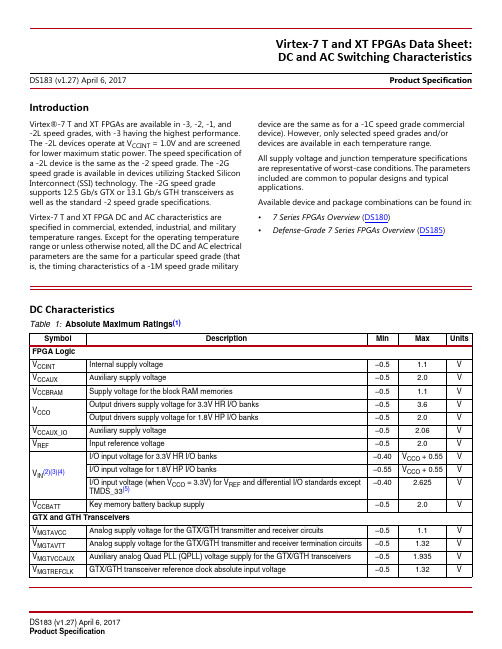
IntroductionVirtex®-7 T and XT FPGAs are available in -3, -2, -1, and -2L speed grades, with -3 having the highest performance. The -2L devices operate at V CCINT=1.0V and are screened for lower maximum static power. The speed specification of a -2L device is the same as the -2 speed grade. The -2G speed grade is available in devices utilizing Stacked Silicon Interconnect (SSI) technology. The -2G speed grade supports 12.5Gb/s GTX or 13.1Gb/s GTH transceivers as well as the standard -2 speed grade specifications.Virtex-7T and XT FPGA DC and AC characteristics are specified in commercial, extended, industrial, and military temperature ranges. Except for the operating temperature range or unless otherwise noted, all the DC and AC electrical parameters are the same for a particular speed grade (that is, the timing characteristics of a -1M speed grade military device are the same as for a -1C speed grade commercial device). However, only selected speed grades and/or devices are available in each temperature range.All supply voltage and junction temperature specifications are representative of worst-case conditions. The parameters included are common to popular designs and typical applications.Available device and package combinations can be found in:•7Series FPGAs Overview (DS180)•Defense-Grade 7Series FPGAs Overview (DS185)DC Characteristics Virtex-7T and XT FPGAs Data Sheet: DC and AC Switching CharacteristicsDS183 (v1.27) April 6, 2017Product SpecificationTable 1:Absolute Maximum Ratings(1)Symbol Description Min Max Units FPGA LogicV CCINT Internal supply voltage–0.5 1.1VV CCAUX Auxiliary supply voltage–0.5 2.0VV CCBRAM Supply voltage for the block RAM memories–0.5 1.1VV CCO Output drivers supply voltage for 3.3V HR I/O banks–0.5 3.6V Output drivers supply voltage for 1.8V HP I/O banks–0.5 2.0VV CCAUX_IO Auxiliary supply voltage–0.5 2.06V V REF Input reference voltage–0.5 2.0VV IN(2)(3)(4)I/O input voltage for 3.3V HR I/O banks–0.40V CCO+0.55V I/O input voltage for 1.8V HP I/O banks–0.55V CCO+0.55V I/O input voltage (when V CCO=3.3V) for V REF and differential I/O standards exceptTMDS_33(5)–0.40 2.625VV CCBATT Key memory battery backup supply–0.5 2.0V GTX and GTH TransceiversV MGTAVCC Analog supply voltage for the GTX/GTH transmitter and receiver circuits–0.5 1.1V V MGTAVTT Analog supply voltage for the GTX/GTH transmitter and receiver termination circuits–0.5 1.32V V MGTVCCAUX Auxiliary analog Quad PLL (QPLL) voltage supply for the GTX/GTH transceivers–0.5 1.935V V MGTREFCLK GTX/GTH transceiver reference clock absolute input voltage–0.5 1.32VDeviceSpeed Grade Designations-3-2G-2-2L-1-1MXC7V585T Vivado tools 2012.4 v1.08or ISE tools 14.2 v1.06N/A Vivado tools 2012.4 v1.08 or ISE tools 14.2 v1.06N/AXC7V2000T N/A Vivado tools 2012.4 v1.07N/AXC7VX330T Vivado tools 2013.1 v1.08or ISE tools 14.5 v1.08N/AVivado tools 2013.1 v1.08 or ISE tools 14.5 v1.08N/AXC7VX415T N/A N/AXC7VX485T Vivado tools 2012.4 v1.08or ISE tools 14.2 v1.06N/A Vivado tools 2012.4 v1.08 or ISE tools 14.2 v1.06N/AXC7VX550T Vivado tools 2013.1 v1.08or ISE tools 14.5 v1.08N/A Vivado tools 2013.1 v1.08 or ISE tools 14.5 v1.08N/AXC7VX690T Vivado tools 2013.1 v1.08or ISE tools 14.5 v1.08N/A Vivado tools 2013.1 v1.08 or ISE tools 14.5 v1.08N/AXC7VX980T N/A N/A Vivado tools 2013.1 v1.08 or ISE tools 14.5 v1.08N/AXC7VX1140T N/A Vivado tools 2013.1 v1.08N/A XQ7V585T N/A N/A Vivado tools 2013.1 v1.04 or ISE tools 14.5 v1.04XQ7VX330T N/A N/A Vivado tools 2013.1 v1.04 or ISE tools 14.5 v1.04Vivado tools 2013.2 v1.05 or ISE tools 14.6v1.05XQ7VX485T N/AN/A Vivado tools 2013.1 v1.04 or ISE tools 14.5 v1.04XQ7VX690TN/AN/AVivado tools 2013.1 v1.04 or ISE tools 14.5v1.04N/AVivado tools 2013.1 v1.04 or ISE tools 14.5v1.04N/AXQ7VX980T N/A N/AN/AVivado tools 2013.1 v1.04 orISE tools 14.5 v1.04N/ADescriptionI/O Bank TypeSpeed Grade Units -3-2/-2L/-2G -1/-1M SDR LVDS transmitter (using OSERDES; DATA_WIDTH =4 to 8)HR 710710625Mb/s HP 710710625Mb/s DDR LVDS transmitter (using OSERDES; DATA_WIDTH =4 to 14)HR 12501250950Mb/s HP 160014001250Mb/s SDR LVDS receiver (SFI-4.1)(1)HR 710710625Mb/s HP 710710625Mb/s DDR LVDS receiver (SPI-4.2)(1)HR 12501250950Mb/s HP160014001250Mb/sDevice Speed Grade Designations-3-2G -2-2L -1-1MTable 18:Maximum Physical Interface (PHY) Rate for Memory Interfaces IP available with the Memory Interface Generator(1)(2)Memory Standard I/O Bank Type V CCAUX_IOSpeed GradeUnits -3-2/-2L/-2G-1-1M4:1 Memory ControllersDDR3HP 2.0V1866(3)1866(3)16001066Mb/s HP 1.8V160013331066800HR N/A10661066800800DDR3L HP 2.0V1600160013331066Mb/s HP 1.8V13331066800800HR N/A800800667N/ADDR2HP 2.0V800800800667Mb/s HP 1.8VHR N/A533RLDRAM III HP 2.0V800667667550MHz HP 1.8V550500450400HR N/A N/A2:1 Memory ControllersDDR3HP 2.0V10661066800667Mb/s HP 1.8VHR N/ADDR3L HP 2.0V10661066800667Mb/s HP 1.8VHR N/A800800667N/ADDR2HP 2.0V800800800667Mb/s HP 1.8VHR N/A533QDR II+(4)HP 2.0V550500450300MHz HP 1.8VHR N/A500450400300RLDRAM II HP 2.0V533500450400MHz HP 1.8VHR N/ALPDDR2HP 2.0V667667667533Mb/s HP 1.8VHR N/ANotes:1.V REF tracking is required. For more information, see the Zynq-7000 AP SoC and 7Series Devices Memory Interface Solutions User Guide(UG586).2.When using the internal V REF, the maximum data rate is 800Mb/s (400MHz).3.For designs using 1866Mb/s components, contact Xilinx Technical Support.4.The maximum QDRII+ performance specifications are for burst-length 4 (BL=4) implementations. Burst length 2 (BL=2) implementationsare limited to 333MHz for all speed grades and I/O bank types.。

I N S T A L L A T I O N I N S T R U C T I O N SSide Speakers AccessoryFLR100FLR100Installation Instructions2DISCLAIMERMilestone AV Technologies and its affiliated corporations and subsidiaries (collectively "Milestone"), intend to make thismanual accurate and complete. However, Milestone makes no claim that the information contained herein covers all details,conditions or variations, nor does it provide for every possible contingency in connection with the installation or use of this product. The information contained in this document is subject to change without notice or obligation of any kind. Milestone makes no representation of warranty, expressed or implied,regarding the information contained herein. Milestone assumes no responsibility for accuracy, completeness or sufficiency of the information contained in this document.Chief® is a registered trademark of Milestone AV Technologies.All rights reserved.IMPORTANT WARNINGS AND CAUTIONS!WARNING: A WARNING alerts you to the possibility ofserious injury or death if you do not follow the instructions.CAUTION: A CAUTION alerts you to the possibility ofdamage or destruction of equipment if you do not follow the corresponding instructions.WARNING:Failure to read, thoroughly understand, andfollow all instructions can result in serious personal injury,damage to equipment, or voiding of factory warranty! It is the installer’s responsibility to make sure all components are properly assembled and installed using the instructions provided.WARNING:Failure to provide adequate structural strengthfor this component can result in serious personal injury or damage to equipment! It is the installer’s responsibility to make sure the structure to which this component is attached can support five times the combined weight of all equipment.Reinforce the structure as required before installing the component.WARNING:Exceeding the weight capacity can result inserious personal injury or damage to equipment! It is the installer’s responsibility to make sure the combined weight of all components located on the FLR100 does not exceed 20 lbs (9.1 kg) on each side.LEGENDApretar elemento de fijación Befestigungsteil festziehen Apertar fixador Serrare il fissaggio Bevestiging vastdraaien Serrez les fixations Aflojar elemento de fijación Befestigungsteil lösen Desapertar fixador Allentare il fissaggio Bevestiging losdraaien Desserrez les fixations Llave de boca Gabelschlüssel Chave de bocas Chiave a punte aperte Steeksleutel Clé à fourcheMarcar con lápiz Stiftmarkierung Marcar com lápis Segno a matita Potloodmerkteken Marquage au crayon Destornillador Phillips Kreuzschlitzschraubendreher Chave de fendas Phillips Cacciavite a stella Kruiskopschroevendraaier Tournevis à pointe cruciforme Adjust Ajustar Einstellen Ajustar Regolare Afstellen AjusterInstallation Instructions FLR100 DIMENSIONS3FLR100Installation Instructions TOOLS REQUIRED FOR INSTALLATION#21/2"PARTS45Figure 12.Install and tighten the knob (G) on each speaker extension.(See Figure 2)order to tighten the side speaker bushings.Figure 3FLR100Installation Instructions6Attaching Speakers and Brackets1.Attach speakers (not included) to speaker brackets (C)following instructions included with speakers.2.Loosely attach one 1/4-20 x 1/2" hex head cap screw (D),one 1/4" lock washer (E) and one 1/4" flat washer (F) to top of each of the speaker brackets (C). (See Figure 4)3.Hang speaker brackets (with attached speakers) on the left and right speaker extensions, and loosely attach bottom of speaker brackets (C) to speaker extensions using one1/4-20 x 1/2" hex head cap screw (D), one 1/4" lock washer (E) and one1/4" flat washer (F) on each speaker extension.(See Figure 4)Figure 44.Push speakers into desired position by lifting slightly on speakers to enable them to slide more easily.5.Adjust and level speaker brackets (C) using lower slot. (See Figure 4)6.Tighten all four fasteners.7.Turn knob (G) outward on both left and right speaker brackets until the knob contacts the wall. This will allow vertical leveling of the speakers.Installation Instructions FLR1007FLR100Installation InstructionsUSA/InternationalA 8401 Eagle Creek Parkway, Savage, MN 55378P 800.582.6480 / 952.894.6280F 877.894.6918 / 952.894.6918EuropeA Fellenoord 130 5611 ZB EINDHOVEN, The Netherlands P +31 (0)40 2668620F +31 (0)40 2668615Asia PacificARoom 24F, Block D, Lily YinDu International BuildingLuoGang, BuJi Town, Shenzhen, CHINA.P +86-755-8996 9226F +86-755-8996 9217Chief Manufacturing, a products division of Milestone AV Technologies 8807-0000832009 Milestone AV Technologies, a Duchossois Group Company 01/09。
Application description 03/2014 LOGO! 0BA7Set 9Warranty and liabilityS i e m e n s A G 2014A l l r i g h t s r e s e r v e dWarranty and liabilityNoteThe Application Examples are not binding and do not claim to be complete regarding the circuits shown, equipping and any eventuality. The Application Examples do not represent customer-specific solutions. They are only intended to provide support for typical applications. You are responsible for ensuring that the described products are used correctly. These application examples do not relieve you of the responsibility to use safe practices in application, installation,operation and maintenance. When using these Application Examples, you recognize that we cannot be made liable for any damage/claims beyond the liability clause described. We reserve the right to make changes to these Application Examples at any time without prior notice.If there are any deviations between the recommendations provided in these application examples and other Siemens publications – e.g. Catalogs – the contents of the other documents have priority.We do not accept any liability for the information contained in this document.Any claims against us – based on whatever legal reason – resulting from the use of the examples, information, programs, engineering and performance data etc.,described in this Application Example shall be excluded. Such an exclusion shall not apply in the case of mandatory liability, e.g. under the German Product Liability Act (“Produkthaftungsgesetz”), in case of intent, gross negligence, or injury of life,body or health, guarantee for the quality of a product, fraudulent concealment of a deficiency or breach of a condition which goes to the root of the contract (“wesentliche Vertragspflichten”). The damages for a breach of a substantialcontractual obligation are, however, limited to the foreseeable damage, typical for the type of contract, except in the event of intent or gross negligence or injury to life, body or health. The above provisions do not imply a change of the burden of proof to your detriment.Any form of duplication or distribution of these Application Examples or excerpts hereof is prohibited without the expressed consent of Siemens Industry Sector.Security informa-tionSiemens provides products and solutions with industrial security functions that support the secure operation of plants, solutions, machines, equipment and/or networks. They are important components in a holistic industrial securityconcept. With this in mind, Siemens’ products and solutions undergo continuous development. Siemens recommends strongly that you regularly check for product updates.For the secure operation of Siemens products and solutions, it is necessary to take suitable preventive action (e.g. cell protection concept) and integrate each component into a holistic, state-of-the-art industrial security concept. Third-party products that may be in use should also be considered. For more information about industrial security, visit /industrialsecurity .To stay informed about product updates as they occur, sign up for a product-specific newsletter. For more information, visit .Table of contentsS i e m e n s A G 2014A l l r i g h t s r e s e r v e dTable of contentsWarranty and liability ................................................................................................... 21Task (42)Solution............................................................................................................... 42.1Overview of the general solution .......................................................... 42.2Hardware and software components used. (53)Functional Mechanisms of this Application (6)3.1Blinds .................................................................................................... 63.2Roof hatch ............................................................................................ 73.3Heating ................................................................................................. 73.4Garden watering ................................................................................... 83.5Interior and exterior lighting (84)Installation (9)4.1Connection configuration master and slave LOGO! ............................ 94.2Software installation (115)Operation of the Application (11)5.1LOGO! TD functions ........................................................................... 115.2Operation ............................................................................................ 125.2.1Operating the blinds ........................................................................... 125.2.2Operating panic function for the lighting (136)Related Literature (14)6.1Bibliographic references ..................................................................... 146.2Internet links (14)7History (14)S i e m e n s A G 2014A l l r i g h t s r e s e r v e d1TaskIntroductionIn residential house, the following functions shall be controlled manually or automatically: Blinds Roof hatchInterior and exterior lighting including panic switch Heating Garden wateringThe manual or automatic mode can be selected via the selection button.Depending on time and day, the blinds are automatically opened or closed and the garden watering is switched on or off.Depending on the temperature, the roof hatches can be opened or closed and the heating switched on or off.If the maintenance mode is set for the blinds, manual or automatic closing is blocked.The states of the respective house functions are displayed on a text display.2Solution2.1Overview of the general solutionFigure 2-1In the automation solution, one LOGO! 0BA7 (1) is used as master and one as slave, which both communicate with each other via a compact switch module (6).One PT100 (9) and one PT1000- (10) temperature sensor each are connected to the RTD expansion module (5), and they are used to control the temperatures in different building areas. Further inputs and outputs of the configuration can be added at any time via DM16 24R (2) or DM8 24R (3) expansion modules. The blinds (14) and the roof hatch (12) can be opened or closed manually via buttons.The exterior and the interior lighting can be switched on and off via buttons (12). All lights are switched off via a central off button. For each button in the house, a panic function is configured so when pressing longer than 3 seconds, all lights areswitched on for a certain amount of time and switched off with automatic time delayor pressing the button for another 3 seconds.S i e m e n s A G 2014A l l r i g h t s r e s e r v e dAn FI protective switch (18) provides the necessary security. Additionally, the power supply for the first, second or third line of the distribution box can be switched off via line protection switch (16, 17).Via LOGO! TD (8), the blinds, the lights and the roof hatch can be controlled centrally and the automatic mode can be switched on and off. Switching the maintenance mode and garden watering on and off, as well as changing the setpoint values for the heating is possible.Advantages/BenefitsSimple execution and clear operation and monitoring of a house control withLOGO! OBA7 and LOGO! TD Adjustable automatic function of the house control with times and days, whichcan be adjusted individually Protection of the blinds for maintenance worksExcellent energy efficiency by monitoring the heating depending on the roomtemperature and the given setpoint value Central house control via LOGO! TDPresence simulation when absent through automatic opening and closing theblinds via a random generator Simultaneously switching all lights on and off via panic buttonsControl of several areas and functionalities of a house control via stillunassigned inputs and outputs2.2Hardware and software components usedThis application has been generated using the following components:Hardware componentsTable ponentQty.Order number Note1. LOGO! 12/24RCE26ED1052-1MD00-0BA72. LOGO! DM16 24R 26ED1055-1NB10-0BA03. LOGO! DM 8 24R 26ED1055-1HB00-0BA04. LOGO! AM2 AQ 16ED1055-1MM00-0BA15. LOGO! AM2 RTD16ED1055-1MD00-0BA16. LOGO! CSM 12/24COMPACT SWITCH MODUL 16GK7177-1MA10-0AA0 Optional: for expanding the plant.7. LOGO! POWER 24V/2,5 A 16EP1332-1SH438. LOGO! TD16ED1055-4MH00-0BA09.PT100 temperature sensors1Available in specializedelectronics shops Alternatively, PT100 or PT1000 temperature sensors can be used 10. PT1000 temperature sensors 111.DELTA PUSHB. INSERT FM1 NO CONTACT55TD212012. I-SYST. TWH, ROCKEROFF/CO FOR PUSHBUTTON 55TG620113.DELTA PUSHB. INSERT FM DOUBLE PUSHBUTTON,2 NO CONTACTS25TD2111S i e m e n s A G 2014A l l r i g h t s r e s e r v e dponent Qty.Order number Note14. I-SYST. TWH, ROCKERBLIND PUSHBUTTON 25TG621415.DELTA LINE TWH, FRAME 1F 8065TG2551-016. Circuit-breaker 35SY4106617. Circuit-breaker 15SY4506618. FI protective switch15SM33116KLConfiguration software / toolsTable ponentQty.Order number Note1.LOGO!Soft Comfort V716ED1058-0BA02-0YA1Sample files and projectsTable 2-3No.ComponentNote2. 64143308_LOGO!_Set9_Master_Slave_en.lscLOGO!Soft Comfort configuration forLOGO! 0BA73Functional Mechanisms of this Application3.1BlindsInputs/outputsTable 3-1No.HardwareLOGO!Program inputs/outputs 1.Blinds button left up (closer)Master I1I12.Blinds button left down (closer)Master I2I23.Blinds button right up (closer) Master I 3I34.Blinds button right down (closer)Master I4I45.Blinds end switch left open (opener)Master I5I56.Blinds end switch left close (opener)Master I6I67.Blinds end switch right open (opener)Master I7I78.Blinds end switch right close (opener)Master I8I89.Blinds motor left up Master Q1Q110.Blinds motor left down Master Q2Q211.Blinds motor right up Master Q3Q312.Blinds motor right downMaster Q4Q4S i e m e n s A G 2014A l l r i g h t s r e s e r v e dFunction descriptionFor each blind, a 0.5 seconds pause for the direction change was programmed for protecting the motor against direct rerouting.In manual mode, the blinds are operated via buttons and LOGO! TD (see Table 3-1,Table 5-1 No. 3, and Table 5-2).With LOGO! function block “Astronomical clock” the blinds are, in automatic mode,moved up at sunrise and moved down at sunset during the week. On the weekend,the blinds are moved up at 08:00 h and down at 20:00 h. A random generator can delay the time of automatic opening and closing up to 30 minutes. Even though the house is empty, this makes it seem that somebody is in the house.In maintenance mode, the blinds move up. Closing the blinds only becomes possible again when the maintenance mode is deactivated.In configuration mode, the parameters of the function blocks (“weekday”, “weekend”,“astro.cl”, “random”) can be changed on the LOGO! display and LOGO! TD.3.2Roof hatchInputs and outputsTable 3-2No.HardwareLOGO!Program inputs/outputs 1.Button roof hatch (closer)Master DM16 l1I92.Roof hatch end switch open (opener)Master DM16 l2I103.Roof hatch end switch close (opener)Master DM16 I3I114.Roof hatch motor up Master DM16 Q1Q55.Roof hatch motor downMaster DM16 Q2Q6Function descriptionFor each roof hatch, a 0.5 seconds pause for the direction change was programmed for protecting the motor against direct rerouting.In manual mode, the roof hatch is exclusively operated via the button.In automatic mode, the “aut.roo” (analog threshold value switch) function block controls the roof hatch depending in the temperature.In configuration mode, the parameters of the “aut.roo” function block can be changed on the LOGO! display and LOGO! TD.NoteWhen using a rain sensor (see LOGO! Set 11), the roof hatch is closed depending on the weather.3.3HeatingInputs and outputsTable 3-3No.HardwareLOGO!Program input/output 1.PT100 temperature sensorMaster RTD A1AI3S i e m e n s A G 2014A l l r i g h t s r e s e r v e dNo.HardwareLOGO!Program input/output 2.PT1000 temperature sensor Master RTD A2AI43.Switch on/off heating room 1Master DM8 Q1Q144.Switch on/off heating room 2Master DM8 Q2Q13Function descriptionThe heaters are switched on and off via the function blocks “heater1” (Analog Comparator) and “heater2” (Analog Comparator).NoteIn the LOGO! basic device (master), the standard setting for two analog inputs are used so the RTD expansion module has the inputs AI3 and AI4.3.4Garden wateringFunction descriptionIn manual mode, the garden watering is operated via LOGO! TD (see Table 5-1, No. 8).In automatic mode, the garden watering is switched on in the morning at 09:00 h and in the evening at 20:00 h for 10 minutes.In configuration mode, the days and times of the weekly timer switch (function block “watering”)can be changed on the LOGO! display and LOGO! TD.NoteWhen using a rain sensor (see LOGO! Set 11), the garden watering is suppressed depending on the weather.3.5Interior and exterior lightingInputs and outputsTable 3-4No.HardwareLOGO!Program input/output 1.Button inside left on/off(integrated panic button)Slave I1NI1(Network input 1)2.Light button inside right on/off(integrated panic button)Slave I2NI2(Network input 2)3.Exterior lighting button on/off(integrated panic button)Slave I3NI3(Network input 3)4.Central off button(integrated panic button)Slave I4NI4(Network input 4)5.Light lighting window inside leftSlave Q1NQ1(Network output 1)6.Light lighting window inside rightSlave Q2NQ2(Network output 2)S i e m e n s A G 2014A l l r i g h t s r e s e r v e dNo.HardwareLOGO!Program input/output 7.LED exterior lightingSlave Q3NQ3(Network output 3)Function descriptionThe lights are operated via button and LOGO! TD (see Table 3-4 and Table 5 3).NoteSignals pending at the inputs of a slave LOGO! should normally be pending for 0.5 seconds so the signals can be transferred safely.4Installation4.1Connection configuration master and slave LOGO!NoteChanges of the IP address or the master-slave mode are only possible in “STOP” mode.Table 4-1S i e m e n s A G 2014A l l r i g h t s r e s e r v e dNoteThe IP addresses and subnet masks of the master and slave LOGO!, and of the network card or USB Ethernet Adapter for the network connection to the PC,must always be set so all devices are located in the same subnet (see Table 4-2).IP addresses and subnet masksTable 4-2No.Device IP address Subnet mask Gateway 1.Master LOGO!192.168.1.10255.255.255.00.0.0.02.Slave LOGO!192.168.1.11255.255.255.00.0.0.03.Network card or USB Ethernet Adapter fornetwork connection to the PC192.168.1.12255.255.255.00.0.0.0Note The respective setup guidelines for LOGO! must generally be followed.CAUTIONFor this application, it must be observed for the wiring that all LOGO!signals are designed in 24V.If a combination of 230V and 24V is required, a 230V basic device must be used. Between a 230V basic device and a 24V expansion module, an analog module for potential separation must be used.S i e m e n s A G 2014A l l r i g h t s r e s e r v e d 4.2Software installation Note It is assumed that the necessary LOGO!Soft Comfort V7 software has beeninstalled on your PC and that you are familiar with the basic handling of this software.5Operation of the ApplicationThe application is operated via buttons. Certain functions are additionally operated via LOGO! TD. The states of the functions are displayed on the LOGO! display and LOGO! TD (e.g.: Panic function: All lights are on!).5.1LOGO! TD functions Table 5-1No.Description / ActivityFigure / Explanation 1.Blinds menu Actual mode F2: change automatic/manual F3: activating maintenance works 2.Blinds menu maintenance works activated F3: Deactivate maintenance3.Blinds menuF2: All blinds upBar display for blindsF3: All blinds down4.Lights menuAll lights onAll lights off5.Panic function activatedPress OK for acknowledgementAll lights are on!Date/timeAll lines are displayed as “ticker line for line”(changes between both displays)S i e m e n s A G 2014A l l r i g h t s r e s e r v e d No.Description / Activity Figure / Explanation6.Roof hatch menuManual modeBar display for roof hatchChange automatic/manual 7.Roof hatch menuAutomatic modeOpen when above 28°Cor below 25°CLine 3 and 4 are displayed as “ticker line for line”(changes between both displays)8.Garden watering menuStatus on/offMode/F3: watering on/offF2: change automatic/manualLine 3 and 4 are displayed as “ticker line for line”(changes between both displays)9.Room1 (temperature control) Temperature/heating on/off Setpoint value F2: increase, F3: reduceNote On LOGO! TD, the F1 key enables navigating backwards and the F4 keyforwards. If the picture for the panic function is activated, it stays when pressing F1 or F4 until it is acknowledged with the OK button on LOGO! or LOGO! TD.5.2OperationHow to use the application is explained using the blinds and the lighting.5.2.1Operating the blindsIn the “Blinds menu” of LOGO! TD you check whether the manual mode is active.Table 5-2No.Description / Activity LOGO! TD1. Press the up button for left blind for atleast 0.5 seconds.S i e m e n s A G 2014A l l r i g h t s r e s e r v e d No.Description / Activity LOGO! TD2. Left blind moves up into the endposition.Repeat the process for moving downwith the close button.3. If during motion the button for theopposite direction is pressed, themotion stops. When pressing the buttonfor the opposite direction for longer (0.5seconds), the motion in opposite direction is activated.Table 5-3No.Description / Activity LOGO! TD1. If all blinds shall move up, press the F2button (all blinds up) in the “blindsmenu” of LOGO! TD for at least 0.25seconds and F3 (all blinds down) formoving down. If during motion theF button for the opposite directionis pressed, the motion stops. Whenpressing the F button for the oppositedirection longer (0.25 seconds) themotion in opposite direction is activated.5.2.2Operating panic function for the lighting Table 5-4No.Description / Activity LOGO! TD1. When pressing a light button for morethan 3 seconds, the panic functionswitches on all lights in the house andthe message text for the panic functionappears on the LOGO! display andLOGO! TD.2. Pressing the button again for more than3 seconds switches the panic functionand all lights back off.6 Related LiteratureS i e m e n s A G 2014A l l r i g h t s r e s e r v e d 6Related Literature 6.1Bibliographic referencesThe following list is by no means complete and only provides a selection of appropriate information.Table 6-1Topic Title\1\LOGO!LOGO! Practical TrainingAuthors: Uwe Graune; Mike Thielert; Ludwig WenzlPublisher: Publicis PublishingISBN: 978-3-89578-338-86.2Internet linksThe following list is by no means complete and only provides a selection of appropriate sources.Table 6-2Topic Link \1\LOGO! Information /mcms/programmable-logic-controller/en/logic-module-logo/Pages/Default.aspx \2\LOGO! Starter Kit /mcms/programmable-logic-controller/en/logic-module-logo/logo-starter-kit/Pages/Default.aspx \3\Link to this document /WW/view/en/64143308\4\Siemens Industry Online Support \5\LOGO! Manuals /WW/view/en/10805245/133300\6\LOGO! Forum /WW/forum/guests/Conferences.aspx?Language=en \7\LOGO!Software Updates /mcms/programmable-logic-controller/en/logic-module-logo/demo-software/Pages/Default.aspx \8\LOGO! ApplicationExamples /mcms/programmable-logic-controller/en/logic-module-logo/application-examples/Pages/Default.aspx 7HistoryTable 7-1Version:Date Modifications V1.004/2013First version V1.103/2014Layout changes and addition of security advice。
河南有线电视网络集团有限公司河南有线数字电视系统卫星信号安全系统工程(项目编号:0005 )投标文件招标文件编号:HNYXSZ015投标单位:北京蓝拓扑电子技术有限公司投标日期: 2010年 1 月26日目录一、投标书.................................. 错误!未定义书签。
第1章投标函 ................................ 错误!未定义书签。
第3章投标系统质量偏离表..................... 错误!未定义书签。
第4章投标书附件............................. 错误!未定义书签。
投标产品能达到的质量等级和技术指标 ..... 错误!未定义书签。
详细的交货清单......................... 错误!未定义书签。
二、资格证明文件 ............................ 错误!未定义书签。
第5章营业执照复印件......................... 错误!未定义书签。
第6章法定代表人授权委托书................... 错误!未定义书签。
第7章产品资质证明文件....................... 错误!未定义书签。
国家广电总局检测报告................... 错误!未定义书签。
软件著作权登记证书..................... 错误!未定义书签。
三、其他证明资料 ............................ 错误!未定义书签。
第8章投标单位情况表......................... 错误!未定义书签。
单位概况............................... 错误!未定义书签。
最近两年经审计的财务报表 ............... 错误!未定义书签。
近年来销售情况一览表................... 错误!未定义书签。
XADC SpecificationsTable 106:XADC SpecificationsParameter Symbol Comments/Conditions Min Typ Max Units V CCADC=1.8V±5%, V REFP=1.25V, V REFN=0V, ADCCLK=26MHz, –55°C≤T j≤125°C, Typical values at T j=+40°CADC Accuracy(1)Resolution12––Bits Integral Nonlinearity(2)INL–40°C≤T j≤100°C––±2LSBs–55°C≤T j<–40°C; 100°C<T j≤125°C––±3LSBs Differential Nonlinearity DNL No missing codes, guaranteed monotonic––±1LSBs Offset Error Unipolar–40°C≤T j≤100°C––±8LSBs–55°C≤T j<–40°C; 100°C<T j≤125°C––±12LSBs Bipolar–55°C≤T j≤125°C––±4LSBs Gain Error––±0.5% Offset Matching––4LSBs Gain Matching––0.3% Sample Rate––1MS/s Signal to Noise Ratio(2)SNR F SAMPLE=500KS/s, F IN=20KHz60––dB RMS Code Noise External 1.25V reference––2LSBsOn-chip reference–3–LSBs Total Harmonic Distortion(2)THD F SAMPLE=500KS/s, F IN=20KHz70––dB Analog Inputs(3)ADC Input Ranges Unipolar operation0–1VBipolar operation–0.5–+0.5VUnipolar common mode range (FS input)0–+0.5VBipolar common mode range (FS input) +0.5–+0.6V Maximum External Channel Input Ranges Adjacent analog channels set within these rangesshould not corrupt measurements on adjacentchannels–0.1–V CCADC VAuxiliary Channel Full Resolution Bandwidth FRBW250––KHzOn-Chip SensorsTemperature Sensor Error–40°C≤T j≤100°C––±4°C–55°C≤T j<–40°C; 100°C<T j≤125°C––±6°C Supply Sensor Error–40°C≤T j≤100°C––±1%–55°C≤T j<–40°C; 100°C<T j≤125°C––±2% Conversion Rate(4)Conversion Time - Continuous t CONV Number of ADCCLK cycles26–32Cycles Conversion Time - Event t CONV Number of CLK cycles––21Cycles DRP Clock Frequency DCLK DRP clock frequency8–250MHz ADC Clock Frequency ADCCLK Derived from DCLK1–26MHz DCLK Duty Cycle40–60%Configuration Switching Characteristics XADC Reference (5)External ReferenceV REFP Externally supplied reference voltage 1.20 1.25 1.30V On-Chip Reference Ground V REFP pin to AGND, –40°C ≤T j ≤100°C1.2375 1.25 1.2625V Ground V REFP pin to AGND, –55°C ≤T j <–40°C;100°C <T j ≤125°C1.225 1.25 1.275VNotes:1.Offset and gain errors are removed by enabling the XADC automatic gain calibration feature. The values are specified for when this feature is enabled.2.Only specified for bitstream option XADCEnhancedLinearity =ON.3.See the ADC chapter in the 7Series FPGAs and Zynq-7000 SoC XADC Dual 12-Bit 1 MSPS Analog-to-Digital Converter User Guide (UG480) for a detailed description.4.See the Timing chapter in the 7Series FPGAs and Zynq-7000 SoC XADC Dual 12-Bit 1 MSPS Analog-to-Digital Converter User Guide (UG480) for a detailed description.5.Any variation in the reference voltage from the nominal V REFP = 1.25V and V REFN = 0V will result in a deviation from the ideal transfer function. This also impacts the accuracy of the internal sensor measurements (i.e., temperature and power supply). However, for external ratiometric type applications allowing reference to vary by ±4% is permitted.Table 107:Configuration Switching CharacteristicsSymbolDescription Speed Grade Units -3E -2E/-2I/-2LI -1C/-1I -1Q/-1LQ Power-up Timing CharacteristicsT PL (1)Program latency 5.00 5.00 5.00 5.00ms, Max T POR Power-on reset (50ms ramp rate time)10/5010/5010/5010/50ms, Min/Max Power-on reset (1ms ramp rate time) with the power-onreset override function disabled;(devcfg.CTRL.PCFG_POR_CNT_4K =0).(2)10/3510/3510/3510/35ms, Min/Max Power-on reset (1ms ramp rate time) with the power-onreset override function enabled;(devcfg.CTRL.PCFG_POR_CNT_4K = 1).(2)2/82/82/82/8ms, Min/Max T PROGRAMProgram pulse width 250.00250.00250.00250.00ns, Min Boundary-Scan Port Timing Specifications T TAPTCK /T TCKTAPTMS and TDI setup/hold 3.00/2.00 3.00/2.00 3.00/2.00 3.00/2.00ns, Min T TCKTDOTCK falling edge to TDO output 7.007.007.007.00ns, Max F TCKTCK frequency 66.0066.0066.0066.00MHz, Max Internal Configuration Access Port F ICAPCKInternal configuration access port (ICAPE2)100.00100.00100.00100.00MHz, Max Device DNA Access Port F DNACKDNA access port (DNA_PORT)100.00100.00100.00100.00MHz, Max Notes:1.To support longer delays in configuration, use the design solutions described in the 7Series FPGA Configuration User Guide (UG470).2.For non-secure boot only. Measurement is made when the PS is already powered and stable, before power cycling the PL.Table 106:XADC Specifications (Cont’d)ParameterSymbol Comments/Conditions Min Typ Max Units。
CyberVOD 7校园多媒体信息管理平台一、产品概述远志科技发展近二十年,一直秉承“科技提升教育,将知识分享予每一位华夏学子”的服务理念,潜心致力于中国信息化教育的沿革,引领百人专业研发团队,投入数亿研发资金,研发出超大型CyberVOD 7校园多媒体信息管理平台系统。
CyberVOD 7是一套专门针对学校构建校园网,扩大信息交流与校际合作,充分实现现代教育资讯网络化的知识应用、管理、传播及分享,提供最为专业和优质的多媒体教育资讯直播、点播及广播的大型多功能平台系统软件。
他较之市场中其他VOD系统,无论是功能应用、综合效能,还是系统运行的稳定与安全等,均堪称全球一流!二、产品应用及核心价值1、建立统一、有序的超大型校园知识管理及传播平台!CyberVOD 7将多媒体信息直播、储存、上传、点播、广播、管理等功能应用集为一体,具备完善的信息采集、存储及发布机制。
●学校所有专题讲座、教学活动、精品课堂、电子图书、行政文件、公告等信息,均可转存并导入系统平台进行管理,建立一个强大而有序的知识管理资源库,全校师生均可随时随地分享知识宝库中的各种教学及娱乐资源。
2、建立校园电影院,整合卫星及有线电视直播,让每一台PC都成为网络电视机!●资源库管理专设校园电影院,各种影片资源均可置入,合理安排影片广播排程,全校师生可依据影院各频道的播放排程,自主选择喜欢的影片,从而大大丰富师生的课余生活。
●整合卫星及有线电视直播,如国际卫星频道、央视媒体资源,或Discovery、百家讲坛、ESPN等优质栏目,让每一台PC都能成为网络电视机,让所有师生都能随时随地收看到教育、科技、体育、文艺、资讯、娱乐等各种节目。
3、整合末端投影设备,把所有普通教室都变成网络数字化多媒体教室!●通过整合音视频采集卡、摄像头、有线电视盒、电视机、投影仪、DVD/VCD等末端多媒体硬件设备,充分实现实况直播、有线电视直播、多媒体远程直播等多种知识传播形式。
●把所有普通教室都变成网络数字化多媒体教室,让所有师生尽情体验网络科技带来的高品质视听新环境。
4、打造校园精品课程资源库,为教师备课及学生课后复习提供重要参考!●各专家、教师可通过直播及录制机制,轻松授课并录制精品课程,系统自动录制转储,并上传至CyberVOD系统精品课程资源库中,全面保留及展现优秀教学风采。
●无论是老师备课借鉴教学方法之优长,还是学生课余学习及加深对知识的理解,均可使用CyberVOD系统设置的精品课程资源库,让精致教学无处不在,与现代知识形影不离。
5、直播、点播、广播完美结合,建立自主资源库,随时随地实现远程教学合作与观摩!●CyberVOD 7系统将直播、点播、广播三大机制完美结合,可将名家讲学现场实况直播、录制并保存,自主建立优质教学资源库。
●名家讲学的多媒体资源通过校园网络,让全校师生在教室、办公室、图书馆、学生宿舍等应用场所随时随地点播、广播或下载,聆听名家名段,探求知识真谛,充分实现远程教学合作与观摩。
6、并联各校VOD系统平台,无限扩充资源库,充分实现校际公网合作!●教育城域网中,如教委和各学校均有本系统,可将各系统相互并联,整合不同学校的VOD系统平台及相关教学资源,无限扩充资源量,建立一个超大型的知识库及传播平台。
●校内可跨网段、跨路由直播,若将主服务器和直播服务器架在公网上,还可实现跨Internet环境的直播,其他已建立连接的学校亦可通过公网点播收看直播的现场实况,从而进一步扩大与各校之间的互动合作,最终把各校整合成一个全数字化的网络科技校园城。
三、产品特色及优势CyberVOD 7校园多媒体信息管理平台,提供从现场实况音视频的直播到录制;从资源的点播到管理;从资源的下载到资源的共享一整套全面的功能服务,其特色及优势如下:1、超强稳定的系统整合能力,完美缔造校际平台资源共享!A、与外网VOD系统平台无缝连接,整合校级、院系超大VOD系统集群!●可将综合型大学各院系独立VOD系统,或合并院校的VOD系统串联,形成校际、院系间的VOD系统集群,充分整合各校各科系教学资源管理平台,大大增强超远程资源共享效能。
●只要用户现有的系统符合B/S结构,均可采用外部整合的方式挂接其它VOD平台。
B、强大的资源共享机能,充分分享各校及院系教学资源!●可将多个学校或院系的多个目录服务器互连起来,各服务器中的教学资源管理端口依据实际情况选择性开放或完全开放,实现各系统教学资源的最大化分享及应用。
●大大增加优质资源储备量,降低硬件设备投入,并能让所用用户灵活掌握最前沿的科技教育资讯及相关专业知识。
C、便捷的WebLink功能,让用户灵活高效共享VOD系统资源!●具有便捷的WebLink功能,方便使用者通过其它链接直接访问VOD系统中的资源库,并准确对接相应的多媒体文件,满足高品质、高效率的点播访问服务。
D、尖端智能动态负载平衡技术,让服务器运行稳如泰山!●全新尖端服务器智能动态负载平衡技术,可根据节目的负载状况,自动的在多个媒体服务器中进行资源的调节,以保证系统提供最佳和最稳定的高品质服务。
E、媒体服务器集群结构,实现大并发流!●采用媒体服务器分布式设计和媒体服务器集群技术,可将不同的媒体服务器放置在网络的不同地方,并将它们并联起来,以提升系统的性能,实现大并发流的点播;●百兆网络可实现六十路MPEG-1的媒体流点播;●千兆网络可实现六百路MPEG-1的媒体流点播。
2、高品质现场实况直播及录制,用户身临其境纵览全局!A、现场实况音视频广播速度超快!●现场实况直播,视频传输速率高达每秒25帧以上,画面流畅无延迟,且影音同步效果优质。
B、现场实况录制及直播高效同步运行!●现场直播与录制可同步执行操作,录制生成的文件,重要学术交流及精彩瞬间得以完美保留。
●图像清晰度极高,可达704×576的分辨率,且占用空间少,每小时均不超过300MB。
C、网络环境无限制,完美实现全网直播!●现场实况直播不仅可在同一网段内进行直播,亦可在不同的网段内直播。
●若将主服务器和直播服务器架在公网上,还可实现跨Internet环境的直播,完美实现全网直播。
3、精准定位资源类别管理,全方位满足教学及娱乐之需!A、电子阅览室、影视中心及观摩中心,精准定位,统一管理!●系统中提供多种访问资源和管理资源的方式,可满足用户在不同应用场合对资源使用的需求,成为学校教学、娱乐,以及企业培训的全方位数字化多媒体平台。
●电子阅览室提供电子图书资源的访问服务;影视中心提供电影影片资源的访问服务;观摩中心提供各种教学资源的访问服务。
全校师生可依据精准定位的类别管理各取所需,充分满足日常教学及娱乐之需。
B、教学园地,老师教学的贴心好助手!●教学园地提供完善的课表定制和排课功能,完全可满足学校的日常教学需要,老师将不再为繁琐的“纸上排课”而烦恼,现代化的电子排课大大提高老师的工作效率,并能科学合理地安排课程教学;同时,本系统亦可作为企业培训的平台。
4、人性化管理机能,操作便捷且高效!A、无须安装客户端,IE控制超便利!●系统采用 B/S 结构,IE浏览器中内嵌播放器,可直接实现各种资源点播服务,资源和系统管理均可通过IE浏览器直接远程执行,使用超级便利。
B、强劲的资源管理机能,轻松操作文件批量上传!●支持文件批量上传功能,通过鼠标拖拽,可直接将Windows下的文件或文件夹拖入至VOD系统中,实现文件批量上传功能,突破传统的单个文件上传限制,大大提高了管理员的工作效率。
C、精细的用户权限管理,灵活配置平台服务!●管理员灵活配置平台服务,可分级管理用户权限,轻松控管整个平台资源服务体系。
●系统可提供对不同的组和用户设置不同的权限,还可针对不同的文件夹,赋予不同的群组和用户以不同的权限;●系统管理员可开放权限给目录管理员,进行单个目录资源的控制与管理。
D、人性化管理器界面设计!●采用树形管理目录,如同使用 Windows Explorer,操作简单,易上手。
四、产品构架CyberVOD 7多媒体信息管理平台采用B/S 架构构成(B/S 是Browser/Server 简称,通过浏览器与服务器进行信息交互的架构方式),由1.主服务器,2.媒体存储服务器,3.现场直播服务器,整合相应的周边硬件设备群,通过对外部音视频源的接入,以及管理平台内存的多媒体文件,构成整个校园多媒体信息管理平台;客户端则无需安装任何程序,可直接使用IE浏览器实现对系统平台的管理和使用。
1. CyberVOD 7服务器端A.主服务器●主服务器是CyberVOD 7系统平台的核心中枢,所有IE浏览端实现的功能都依赖于他,主服务器程序需单独安装于信息中心用作主服务器的电脑上。
●主服务器只需一台,其包含目录服务器程序和WEB服务器程序,对客户端提供用户身份的验证以及Web浏览服务,可支持无限用户同时上线并高效使用CyberVOD系统平台。
B.媒体存储服务器●媒体存储服务器是CyberVOD系统平台的能量储备库,用于管理、存储所有媒体文件及课件资源,大量的影音资源集中于此,并纳入统一规范的管理。
●学校可在信息中心准备一台或多台电脑用作媒体存储服务器,随着教学资源的扩大,媒体服务器可无限制增加,再大的资源库,都能被CyberVOD系统所统辖。
●媒体服务器支持集群和动态负载均衡,同时上线操作的用户再多,也不必担心系统当机,媒体服务器集群及负载均衡完美实现大并发流点播服务,超高性能极大满足全校师生之需求。
C.现场直播服务器●现场直播服务器主要用来将外部设备(VCD/DVD机、移动摄像机、有线电视等)模拟音视频信号,通过采集卡转换成数字音视频信号后,以组播的方式传送到网络上,提供给用户点播分享。
●灵活多样的外部音视频资源,如大到国际卫星频道资源、央视1—10套有线电视节目、大型国际学术会议的现场直播,小到校园会议、专题报告、专家讲座、精品课堂等,均能实况直播,校园师生充分共享资源,扩大教学规模。
2. CyberVOD 7客户端A.系统管理员●可由校园信息中心组员担任,负责使用权限与平台整体系统管理维护等工作,设置权限给资源管理员及一般用户,并负责添加媒体服务器,及建置各实况直播平台的环境,协调CyberVOD系统的高效运行。
B.资源管理员●可由学校教师或实验人员担任,负责建立维护公用信息媒体源库。
●可借助系统提供权限与用户管理,提供分组数据上传、阅览与管控,有效管理各教学项目分组之作业与讨论文件内容,使得跨校际与跨科系教学活动,能从系统平台上充分获得相关资源的整合。
C.一般用户●全校师生均可登录系统平台,获得视频点播、频道节目收看等各类数据搜索、下载等功能服务,充分共享资源库中的每一个教学资源。
五、系统应用说明强大的CyberVOD7校园多媒体信息管理平台,在使用上主要包括直播系统、点播系统以及广播系统三大领域,无论是管理员还是用户,均可直接通过IE浏览器登录,全方位、高效便捷的实现对CyberVOD7系统平台的管理与使用。