自控阀数据表
- 格式:xls
- 大小:120.00 KB
- 文档页数:1
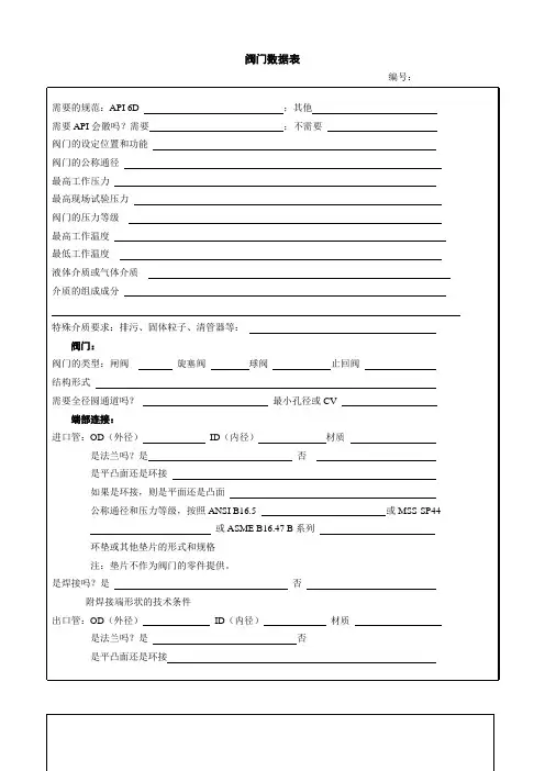
阀门数据表
编号:
如果是环接,则是平面还是凸面
公称通径和压力等级,按照ANSI B16.5 或MSS-SP44
或ASME B16.47 B系列
环垫或其他垫片的形式和规格
注:垫片不作为阀门的零件提供。
是焊接吗?是否
附焊接端形状的技术条件
长度:对结构长度的特殊要求?
阀门的操作:
需要附加操作机构吗?如果需要,则说明下面中的一个尺寸:
对于水平轴的手轮,阀门通道中心线到手轮中心线的距离:英寸
或者,对于垂直轴的手轮,阀门通道中心线到手轮轮缘中心间的距离:英寸。
注:有活动的扳手的旋塞阀,必须单独订购扳手。
需要扳手吗?
需要锁紧装置吗?型式
阀门的支承
需要支承筋或支承腿吗?
其他要求:
补充试验
耐火试验结构是否
NACE MR01-75 是否
泄压:如果需泄压装置,那么你对这些装置有特殊要求吗?
排放连接;有何要求?
旁通连接;有何要求
要求提供的文件
第三方证明或程序/试验:
需要涂漆或上涂层吗?
填表人:填表日期:
Rev:01。
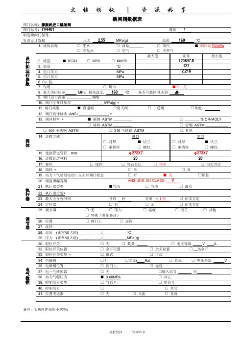
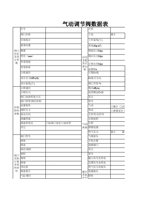
阀门名称:膨胀机进口跳闸阀 阀门标号:TV4401 数量 1管道设计数据压力 2.55 MPa(g)温度 160 o C1. 流体名称 □ 生水 □ 油品_______ □ 蒸汽 ■ 制冷剂R245fa□ 除盐水 □ 空气 □ 天然气最大值 正常 最小值2. 流量 ■ KG/H □ M 3/S □ NM 3/S129847.8 3. 温度 o C127 4. 进口压力 MPa2.218 5. 出口压力 MPa6. C V 值:7. 作用: □ 调节 ■开-关8. 最大关闭压差 MPa, 最高温度. 160 oC 是否可能同时达到 是 9. 阀门进口流速 ____________ M/S10. 阀门全开时压差 _______________ MPa(g) *11. 阀门类型 ■ 直通阀□角式阀□ 三通阀□其他:12. 阀门设计标准 ANSI _______________ *13. 阀体材料 * ■ 碳钢 ASTM _________ □ _______ % CR-MOLY□ 铸铁 ASTM _________□ 青铜 ASTM ___________ □ 304不锈钢 ASTM _______□ 316不锈钢 ASTM ____________□ 其他 ___________14. 连接方式进口出口□ 对焊 ■ 法兰. □ 对焊 ■ 法兰. □ 承插焊□ 螺纹. □ 承插焊□ 螺纹.15. 连接管道管径 mm φ273X7 φ273X7 16. 连接管道材料 20 2017. 特性 □ 线性□ 等百分比□ 快关□ 由卖方定18. 填料 *□ 单□ 双19. 动力(气动或电动)失去时阀门状态 □ 开 ■ 关 □锁住20. 阀座泄漏等级ANSI B16.104 CLASS V21. 执行器类型 ■气动□ 电动 □ 液动 22. 执行器位数* 23. 最大全行程时间 开启 秒 关闭 < 1秒 □ 由卖方定 24. 定位器 □ 有□ 无 □ 由卖方定25. 调节器 □ 无 □ 压力□ 温度.□ 液位□ 其他 □ 特殊(参见备注)26. 位置 □ 阀门上□ 远程27. 流体28. 温度 (正常/最大值) ___________/____________o C 29. 压力 (正常/最大值) ___________/____________MPa(g)30. 限位开关 □ 无 □ 数量□ 电压等级 V A32. 限位开关位置 □ 全开位置 □ 全关位置 □ ___%全开33. 限位开关类型 * □ 形式 _______ □ 形式 _______34. 电磁阀 □无 □交流( Hz)□ 直流□ 电压等级 V35. 电磁阀位置 □ 阀门上 □ 远程37. 电-气转换器 □ 无 □输入信号 至 38. 动力气源压力 ■ 0.60MPa □ 其它 39. 控制信号类型 □ 气信号 □ 电信号40. 控制信号□ □ 其它 41. 位置变送器 □ 无 □ 交流 □ 直流执行器调节器电气数据设计和运行参数阀体管道设计数据压力 2.55 MPa(g)温度 160 o C1. 流体名称 □ 生水 □ 油品_______ □ 蒸汽 ■ 制冷剂R245fa□ 除盐水 □ 空气 □ 天然气最大值 正常 最小值2. 流量 ■ KG/H □ M 3/S □ NM 3/S129847.8 3. 温度 o C127 4. 进口压力 MPa2.218 5. 出口压力 MPa6. C V 值:7. 作用: ■ 调节 □开-关8. 最大关闭压差 MPa, 最高温度. 160 oC 是否可能同时达到 是 9. 阀门进口流速 ____________ M/S10. 阀门全开时压差 _______________ MPa(g) *11. 阀门类型 ■ 直通阀□角式阀□ 三通阀□其他:12. 阀门设计标准 ANSI _______________ *13. 阀体材料 * ■ 碳钢 ASTM _________ □ _______ % CR-MOLY□ 铸铁 ASTM _________□ 青铜 ASTM ___________ □ 304不锈钢 ASTM _______□ 316不锈钢 ASTM ____________□ 其他 ___________14. 连接方式进口出口□ 对焊 ■ 法兰. □ 对焊 ■ 法兰. □ 承插焊□ 螺纹. □ 承插焊□ 螺纹.15. 连接管道管径 mm φ273X7 φ273X7 16. 连接管道材料 20 2017. 特性 □ 线性■ 等百分比□ 快开□ 由卖方定18. 填料 *□ 单□ 双19. 动力(气动或电动)失去时阀门状态 □ 开 ■ 关□ 锁住20. 阀座泄漏等级ANSI B16.104 CLASS IV21. 执行器类型 ■气动□ 电动 □ 液动22. 执行器位数* 23. 最大全行程时间 开启 秒 关闭 秒 □ 由卖方定 24. 定位器 □ 有□ 无 □ 由卖方定25. 调节器 □ 无 □ 压力□ 温度.□ 液位□ 其他 □ 特殊(参见备注)26. 位置 □ 阀门上□ 远程27. 流体28. 温度 (正常/最大值) ___________/____________o C 29. 压力 (正常/最大值) ___________/____________MPa(g)30. 限位开关 □ 无 □ 数量□ 电压等级 V A32. 限位开关位置 □ 全开位置 □ 全关位置 □ ___%全开33. 限位开关类型 * □ 形式 _______ □ 形式 _______34. 电磁阀 □无 □交流( Hz)□ 直流□ 电压等级 V35. 电磁阀位置 □ 阀门上 □ 远程37. 电-气转换器 □ 无 □输入信号 至 38. 动力气源压力 ■ 0.60MPa □ 其它 39. 控制信号类型 □ 气信号 □ 电信号40. 控制信号□ □ 其它 41. 位置变送器 □ 无 □ 交流 □ 直流设计和运行参数执行器调节器电气数据阀体管道设计数据压力 2.55 MPa(g)温度 55 o C1. 流体名称 □ 生水 □ 油品_______ □ 蒸汽 ■ 制冷剂R245fa□ 除盐水 □ 空气 □ 天然气最大值 正常 最小值2. 流量 ■ KG/H □ M 3/S □ NM 3/S129847.8 3. 温度 o C38.4 4. 进口压力 MPa0.215 5. 出口压力 MPa2.2489 6. C V 值:7. 作用: ■ 调节 □开-关8. 最大关闭压差 MPa, 最高温度. 41.5 oC 是否可能同时达到 否 9. 阀门进口流速 ____________ M/S10. 阀门全开时压差 _______________ MPa(g) *11. 阀门类型 ■ 直通阀□角式阀□ 三通阀□其他:12. 阀门设计标准 ANSI _______________ *13. 阀体材料 * ■ 碳钢 ASTM _________ □ _______ % CR-MOLY□ 铸铁 ASTM _________□ 青铜 ASTM ___________ □ 304不锈钢 ASTM _______□ 316不锈钢 ASTM ____________□ 其他 ___________14. 连接方式进口出口□ 对焊 ■ 法兰. □ 对焊 ■ 法兰. □ 承插焊□ 螺纹. □ 承插焊□ 螺纹.15. 连接管道管径 mm φ108X4 φ108X4 16. 连接管道材料 20 2017. 特性 □ 线性■ 等百分比□ 快开□ 由卖方定18. 填料 *□ 单□ 双19. 动力(气动或电动)失去时阀门状态 □ 开 □ 关■ 锁住20. 阀座泄漏等级ANSI B16.104 CLASS I V21. 执行器类型 ■气动□ 电动 □ 液动22. 执行器位数* 23. 最大全行程时间 开启 秒 关闭 秒 □ 由卖方定 24. 定位器 □ 有□ 无 □ 由卖方定25. 调节器 □ 无 □ 压力□ 温度.□ 液位□ 其他 □ 特殊(参见备注)26. 位置 □ 阀门上□ 远程27. 流体28. 温度 (正常/最大值) ___________/____________o C 29. 压力 (正常/最大值) ___________/____________MPa(g)30. 限位开关 □ 无 □ 数量□ 电压等级 V A32. 限位开关位置 □ 全开位置 □ 全关位置 □ ___%全开33. 限位开关类型 * □ 形式 _______ □ 形式 _______34. 电磁阀 □无 □交流( Hz)□ 直流□ 电压等级 V35. 电磁阀位置 □ 阀门上 □ 远程37. 电-气转换器 □ 无 □输入信号 至 38. 动力气源压力 ■ 0.60MPa □ 其它 39. 控制信号类型 □ 气信号 □ 电信号40. 控制信号□ □ 其它 41. 位置变送器 □ 无 □ 交流 □ 直流执行器调节器电气数据设计和运行参数阀体调节阀数据表阀门名称:膨胀机旁路阀 阀门标号:FV4402 数量 1管道设计数据压力 2.55 MPa(g)温度 160 o C1. 流体名称 □ 生水 □ 油品_______ □ 蒸汽 ■制冷剂R245fa□ 除盐水 □ 空气 □ 天然气最大值 正常 最小值2. 流量 ■ KG/H □ M 3/S □ NM 3/S129847.8 3. 温度 o C127 4. 进口压力 Mpa.a2.218 5. 出口压力 MPa0.245 6. C V 值:7. 作用: ■ 调节 □开-关8. 最大关闭压差 MPa, 最高温度. 160 oC 是否可能同时达到 否 9. 阀门进口流速 ____________ M/S10. 阀门全开时压差 _______________ MPa(g) *11. 阀门类型 ■ 直通阀□角式阀□ 三通阀□其他:12. 阀门设计标准 ANSI _______________ *13. 阀体材料 * ■ 碳钢 ASTM _________ □ _______ % CR-MOLY□ 铸铁 ASTM _________□ 青铜 ASTM ___________ □ 304不锈钢 ASTM _______□316不锈钢 ASTM ____________□ 其他 ___________14. 连接方式进口出口□对焊 ■ 法兰. □对焊 ■法兰. □ 承插焊□ 螺纹. □ 承插焊□ 螺纹.15. 连接管道管径 mm φ159X4.5φ159X4.516. 连接管道材料 20 2017. 特性 ■线性□等百分比■ 快开□ 由卖方定18. 填料 *□ 单□ 双19. 动力(气动或电动)失去时阀门状态 ■开 □关□锁住20. 阀座泄漏等级ANSI B16.104 CLASS IV21. 执行器类型 ■气动□ 电动 □ 液动22. 执行器位数* 23. 最大全行程时间 开启 秒 关闭 秒 □ 由卖方定 24. 定位器 □ 有□ 无 □ 由卖方定25. 调节器 □ 无 □ 压力□ 温度.□ 液位□ 其他 □ 特殊(参见备注)26. 位置 □ 阀门上□ 远程27. 流体28. 温度 (正常/最大值) ___________/____________o C 29. 压力 (正常/最大值) ___________/____________MPa(g)30. 限位开关 □ 无 □ 数量□ 电压等级 V A32. 限位开关位置 □ 全开位置 □ 全关位置 □ ___%全开33. 限位开关类型 * □ 形式 _______ □ 形式 _______34. 电磁阀 □无 □交流( Hz)□ 直流□ 电压等级 V35. 电磁阀位置 □ 阀门上 □ 远程37. 电-气转换器 □ 无 □输入信号 至 38. 动力气源压力 ■ 0.60MPa □ 其它 39. 控制信号类型 □ 气信号 □ 电信号40. 控制信号□ □ 其它 41. 位置变送器 □ 无 □ 交流 □ 直流执行器调节器电气数据设计和运行参数阀体调节阀数据表阀门名称:热水旁路阀 阀门标号:数量 1管道设计数据压力 3.0 MPa(g)温度 280 o C1. 流体名称 □ 生水 □ 油品_______ □ 蒸汽 □ 其他 _______■ 除盐水 □ 空气 □ 天然气最大值 正常 最小值2. 流量 ■ KG/H □ M 3/SNM 3/S 300000 3. 温度 o C143 4. 进口压力 MPa1.2 5. 出口压力 MPa6. C V 值:7. 作用: ■ 调节 □开-关8. 最大关闭压差 MPa, 最高温度. 160 oC 是否可能同时达到 是 9. 阀门进口流速 ____________ M/S10. 阀门全开时压差 _______________ MPa(g) *11. 阀门类型 ■ 直通阀□ 角式阀□ 三通阀□其他:12. 阀门设计标准 ANSI _______________ *13. 阀体材料 * ■ 碳钢 ASTM _________ □ _______ % CR-MOLY□ 铸铁 ASTM _________□ 青铜 ASTM ___________ □ 304不锈钢 ASTM _______□316不锈钢 ASTM ____________□ 其他 ___________14. 连接方式进口出口□ 对焊 ■ 法兰. □ 对焊 ■ 法兰. □ 承插焊□ 螺纹. □ 承插焊□ 螺纹.15. 连接管道管径 mm φ273X7 φ273X7 16. 连接管道材料 20 2017. 特性 ■线性□等百分比■ 快开□ 由卖方定18. 填料 *□ 单□ 双19. 动力(气动或电动)失去时阀门状态 ■开 □关□ 锁住20. 阀座泄漏等级ANSI B16.104 CLASS IV21. 执行器类型 ■气动□ 电动 □ 液动22. 执行器位数* 23. 最大全行程时间 开启 秒 关闭 秒 □ 由卖方定 24. 定位器 □ 有□ 无 □ 由卖方定25. 调节器 □ 无 □ 压力□ 温度.□ 液位□ 其他 □ 特殊(参见备注)26. 位置 □ 阀门上□ 远程27. 流体28. 温度 (正常/最大值) ___________/____________o C 29. 压力 (正常/最大值) ___________/____________MPa(g)30. 限位开关 □ 无 □ 数量□ 电压等级 V A32. 限位开关位置 □ 全开位置 □ 全关位置 □ ___%全开33. 限位开关类型 * □ 形式 _______ □ 形式 _______34. 电磁阀 □无 □交流( Hz)□ 直流□ 电压等级 V35. 电磁阀位置 □ 阀门上 □ 远程37. 电-气转换器 □ 无 □输入信号 至 38. 动力气源压力 ■ 0.60MPa □ 其它 39. 控制信号类型 □ 气信号 □ 电信号40. 控制信号□ □ 其它 41. 位置变送器 □ 无 □ 交流 □ 直流执行器调节器电气数据设计和运行参数阀体其他:1)气动执行机构带定位器,采用SMC品牌原装进口产品2)设备使用防爆区域按2区,室外;相关仪表、接线考虑本安型,防护等级IP65。

VALVES SERIES 70, HAND OPERATEDM A VMAV manualvalves221/8’’31/4’’41/2’’FAMILY DIMENSIONS333/255/265/382x3/2FUNCTIONP PPP drawerVL axial leverLE90° leverBRE arranged formanual panelactuatorsOPERATION 14SA pneumatic/mechanical spring*S mech. springB bistableD differentialO stable for 5/3*on demandREPEATED OPERATION 12N CNC normally closedNO normally openOO no indicationCC closed centresOC open centresPC pressure centresFURTHER DETAILS90° LEVER 3/2 1/8”2020 Nmø4.2886.5341786.51.3ø18ø185 VALVES SERIES 70, HAND OPERATED, 1/8”ࡗ It can't be supplied. As working replaced by selector with bistable short lever at 2 positionsVALVES SERIES 70, HAND-OPERATED, 1/4"VALVES SERIES 70, HAND OPERATED, 1/2"DETERMINATION OF FLOW RATE CHARACTERISTICS FORPNEUMATIC VALVESZdeněk VARGA, Petri K ESKI-HONKOLA AAbstract:The standard ISO 6358 is often used for describing flow rate ofpneumatic valves.This standard uses sonic conductance and the critical pressure ratio to calculate mentioned flow rate.Different valves can be compared by these two parameters and an accurate mathematical model of flow rate can be created for an actual v alv e. The presented work is based on the measurements of the charge and the discharge of a tank through a v alv e.Downstream pressure, upstream pressure, temperature for both supply air and pressurized air inside the tank are monitored. The sonic conductance and the critical pressure ratio are obtained from this process as inverse models for two valves.1.I NTRODUCTIONFor this research of pneumatic valves flow rate characteristics a standard proportional pressure regulator VPPM-6L-L-1-G18-0L10H-A4P-S1C1 was selected. Same valve is used another research work of the authors involving an artificial pneumatic muscle. The vale supplied pressurized air to the muscle and the contraction of the muscle depends on the amount of the pressurized air. For creating a mathematical model of the whole system it is important to describe flow rate through the valve, which was the reason for formulation of the flow rate characteristic for our valve.In this case flow rate through the valve is described by the sonic conductance C and the critical pressure ratio b . This description of flow rate through the screening is taken from the ISO standard 6358 and for mathematical model of the pneumatic valve these two constants must be determined. First attempt to determine these two constants was made by measuring flow rate through the valve while increasing upstream pressure. The first measurement showed that precision was lost by the influence of special measuring equipment.An alternative method of measuring flow rate characteristics is described in this paper and is referred as second method. The second method is based on the charge and the discharge of a tank through the valve while downstream pressure, upstream pressure, temperature for supply air and for pressurized air inside the tank is monitored. In this paper the second method is applied for determination the sonic conductance and the critical pressure ratio. Determination of the flow rate characteristic is done to two types of valve; VPPM-6L-L1-G18-0L6H -V1P-S1C1 and VPPM-6L-L-1-G18-0L10H -A4P-S1C1 for reasons of comparing the valves and verification of the applied method.Ing. Zdeněk VARGA, Technical University of Liberec, Department of Applied Cybernetics, Sudentská2,46117Liberec,CzechRepublic,**********************;M.Sc.PetriKeski-H ONKOLA, Aalto University, Engineering design and Production, P.O.Box 14400, 00076 Espoo, Finland,**************************EPJ Web of Conferences , 010 (2012) DOI: 10.1051/epjconf/201225010© Owned by the authors, published by EDP Sciences, 20122. M ETHODSIn the introduction of this paper two methods to determinate flow rate characteristic were mentioned. The first of the methods is based on increasing upstream pressure while the pressurized air goes through a mass flow sensor. This method is explained in detail in the standard ISO 6358. Next two equations which describe the flow rate through the orifices can be found in this standard ISO 6358 [1].1Cp qm 0Cfor p p b 12choked flow (1)1112bb p p Cp q m forp pb 12subsonic flow (2)Custom equipment was manufactured for measuring the flow rate characteristics based on …increasing the upstream pressure”. Part of the valve holding the valve nozzle was replaced with the special equipment. With this setup it was possible to set the nozzle to a required fixed position. Without modifications this could not be done.Figure 1 a) shows the measuring station which was used for measurement and figure 1 b) shows the curvature of dependence flow rate on the upstream pressure. This method has been applied only on valve VPPM-6L-L1-G18-0L6H -V1P-S1C1 because preparing special equipment for holding the nozzle in a constant position is very expensive and work intensive.a) b)Figure 1: Measuring flow rate characteristic by increasing upstream pressurea)schematic of measuring station (1 – pressurized air source, 2 – pressure regulator, 3 – pressure sensor ,4 – pressure sensor, 5 – flow meter) b) Dependence flow rate on theupstream pressureEPJ Web of ConferencesThe second method is based on the charge and the discharge of a tank. In this method an isothermal process is assumed when the state equation of ideal gases (3) is used. mrT pv m (3)Equation (3) is used together with equations (1) and (2). Equations (4) and (5) can be obtained from these and they express a derivative of pressure continuance p 2 in the tank. These equations were used for creating simulation model of charge and discharge of a tank.1212CpV rTpr for p p b 12choked flow (4)1121212bb p p Cp V rT prp p b 12subsonic flow (5)Picture of measuring tank and schematic of measuring equipment used in the experiment implementing the second method can be seen in Figure 2 a) and b).a) b) Figure 2: Measuring flow rate characteristic by charge and discharge of a tank a) The measuring tank b) Measuring schematic (1 –Central compressed air supply, 2 – Filter regulator with backflow function AW30K-F03, 3 – Temperature sensor, 4 – Pressure sensor, 5 – Proportional pneumatic valve VPPM, 6 – Pressure tank, 7 – Data acquisitioncard, 8 – Computer)EFM11For creating a simulation of charge and discharge of a tank, MATLAB® Simulink was used. It makes possible to compare a lot of measured data with mathematical models, which was a great contribution to the work. Measurements made with the two valves were compared to theoretical values.Figure 3 and Figure 4 show two Simulink models created to determine sonic conductance C and the critical pressure ratio b from the measured data. This procedure is described in the next chapter.Figure 3: Simulation schematic of a tank charge in SimulinkFigure 4: Simulation schematic of a tank discharge in Simulink3. R ESULTSTwo types of measurements were made, firstly, the flow rate characteristic was measured by increasing upstream pressure as depicted in Figure 1 and secondly, flow rate characteristic was measured by charge and dischrge of a tank as shown in Figure 2. The results from the first method are shown in Figure 5. Measured data are represented as blue circles. Green curvature represents theoretical approximation obtained as a numerical solution searching sonic conductance C and the critical pressure ratio b.Figure 5: Dependence of flow rate to the upstream pressure – data from the firstmethod measurementFor numerical approximation of the measured data a special program was created in MATLAB® this program used function fminsearch from the MATLAB® toolbox. The function fminsearch finds the minimum of a function, in our case function (2) which describes the flow rate through the orifices for event subsonic flow.The results from first methods:C=6,329e-09 [m^3/(s*Pa)]b=0,1527 [-]As mentioned before this method has been applied only on valve VPPM-6L-L1-G18-0L6H-V1P-S1C1 because preparatio of the special equipment for holding the nozzle in constant position is very expensive and work intensive.The second method of determining the flow rate characteristic uses the results obtained from the charge and discharge of the tank. In fact this second method is used to describe the flow rate (constant of sonic conductance C and the critical pressure ratio b )through the valve in the case when the valve is attached to supply pressure and in the second case, to ambient pressure. The data from the measurements of charging the tank through the valve VPPM-6L-L-1-G18-0L10H -A4P-S1C1 are shown in Figure 6, the same curvature was obtained for the valve VPPM-6L-L1-G18-0L6H-V1P-S1C1with first methodFigure 6: Graph of pressure in a tank on time – data from the measuring charge a tankThe data from the measurement was smoothed by applying the Savitzky-Golay filter and compared to the theoretical model which is shown in Figure 3.Figure 7: Graph of pressure in a tank on time – results from the simulation of charge atank in SimulinkP r e s s u r e [P a ] Time [s] Measured dataMathematic modelRequired valueThe comparison of measured data and simulation is shown in Figure 7 for the final value of pressure inside a tank 8kPa – valve VPPM-6L-L-1-G18-0L10H-A4P-S1C1.Values of critical pressure ratio b for each final pressure in the tank were determined based on knowledge that the linear part of the curvature of the charge is describe by equation (1) and the behaviors of flow rate in the second part of the curvature is described by equation (2). Of note is that the critical pressure ratio b expresses the divide of the downstream and the upstream pressure which flow becomes choked [1].For determination of the critical pressure ratio a derivative of smoothed measured data was made, and the point where the derivative exchanges determines the mentioned critical pressure ratio. The values of sonic conductance C were determined from the equation which describes the flow rate through the orifices for subsonic flow. The results of critical pressure ratio and sonic conductance for different values of upstream pressure are shown in Table 1 and 2.Table 1: The values of critical pressure ratio and sonic conductance determined from the charge of a tank – valve VPPM-6L-L-1-G18-0L10H-A4P-S1C1Upstream pressurep1 [kPa]critical pressure ratiob [-]sonic conductanceC [m^3/(s*Pa)]200 0,56 0,90 e-8300 0,41 1,30 e-8400 0,36 1,55 e-8500 0,40 1,62 e-8600 0,44 1,65 e-8700 0,45 1,65 e-8800 0,46 1,62 e-8Table 2: The values of critical pressure ratio and sonic conductance determined from the charge of a tank – valve VPPM-6L-L1-G18-0L6H-V1P-S1C1Upstream pressurep1 [kPa]critical pressure ratiob [-]sonic conductanceC [m^3/(s*Pa)]200 0,56 1,08e-8 300 0,41 1,43 e-8 400 0,35 1,61 e-8 500 0,37 1,68 e-8 600 0,38 1,72 e-8 700 0,33 1,73 e-8A part of the second method of determination, a constant describing the flow rate through the valve is discharge of a tank. In this method we used a different method of determination for constant C and b , in the first step we provided the measurements of the discharge of a tank and we made a visualization of measured data on the graph see Figure 8.Figure 8: Graph of pressure in a tank on time – data from the measured discharge atankAs in the charge of a tank the Savitzky-Golay filter was applied for smoothing the measured data and determination of constants C and b can be made.Figure 9: Graph of pressure in a tank on time – results from the simulation of dischargea tank in SimulinkTime [s] P r e s s u r e [P a ] Measured dataMathematic modelRequired valueFor evaluation of the constant was used a combination of the simulation of a tank discharge made in Simulink (see Figure 4) and a special program in MATLAB® were used. This special program uses an fminsearch function for searching the mentioned constants. The method of discharge of a tank was used for charting of the silencer influence on the flow rate characteristic (see Table 3 to 5).Table 3: The values of critical pressure ratio and sonic conductance determined from the discharge of a tank – valve VPPM-6L-L-1-G18-0L10H-A4P-S1C1 without silencercritical pressure ratiob [-] sonic conductance C [m^3/(s*Pa)]0,1178 1,7150 e-8Table 4: The values of critical pressure ratio and sonic conductance determine from the discharge of a tank – valve VPPM-6L-L-1-G18-0L10H-A4P-S1C1 with silencercritical pressure ratiob [-] sonic conductance C [m^3/(s*Pa)]0,1017 1,5608 e-8Table 5: The values of critical pressure ratio and sonic conductance determine from the discharge of a tank – valve VPPM-6L-L1-G18-0L6H-V1P-S1C1 without silencercritical pressure ratiob [-] sonic conductance C [m^3/(s*Pa)]0,1153 1,5873e-84. D ISCUSSIONResults from the first and second methods were verified with mathematic models of charge and discharge of a tank in Simulink. When results from the second method are used (see Figures 7 and 9) satisfactory results are obtained. The curvature of the measured data has a very similar shape to the curvature from the mathematic model. Nevertheless, when comparing the results from the first method, which was applied only on valve VPPM-6L-L1-G18-0L6H-V1P-S1C1, we can see a very different value of sonic conductance can be seen, around one decimal place. The pressure ratio is even more different but sonic conductance b from the first method is close to the b from the second method.Differences between the first and second methods are believed to be caused by the special equipment for holding the nozzle in a fixed position. If the results from the first method are used to obtain the mathematic model of charge or discharge, results are very unsatisfactory.In the results chapter the determination of the flow rate characteristic from the measurements was shown with different upstream pressures by charging and discharging the tank. The first method gives us only results for one flow rate, from supply pressure to applied load. In the real application pressurized air comes from a central compressed air supply and the applied load is an artificial pneumatic muscle. The second method gives better overview of behavior of flow rate for both ways in contrast to the first method. During the process of determination of the constants C and b the problem of how to find a derivative while using the second method must be solved. Using the second method to automatically build the mathematic model in MATLAB® still needs work, but in this case it main purpose was to help with verification of results.During the measurements the influence of the silencer/ on flow rate during discharge of the tank was tested. Due to this experiment it can be understood how the behavior of the pneumatic circuit during the process of discharge can be biased. The results from this experiment is noted in Table 3 and 4 and from knowledge gained from measurements and simulations it can be said that the highest value of constant C is very important for the time of discharge and the shape of curvature in the case of discharge.In this paper when it is mentioned that second method provides satisfactory results it is based on literature research of similar test results. This research uncovered a very important annotation about the value of constant b. In the rough estimation of the parameter b (e.g. 0,4 instead of 0,2) results in the error in the valves yields 14% of flow rate rate [5].5. C ONCLUSIONThe goal of this work was to find a method that would allow us to describe the flow rate through the valve. For this method a standard from the ISO 6358 was chosen. Method of increasing upstream pressure which is named in the first method in this paper was applied. This method is explained in the standard ISO 6358. Construction of the valve was a disadvantage for the application of this method for measuring flow rate characteristic on the valve in both ways of flow, from supply to applied load and from applied load to the outlet.The main contribution of this paper is application of the second method where a tank is charged and discharge. With this method we were able to determine the constants that allow the description of flow rate both ways. Process of determining the constant from the charge of a tank is simpler than from the discharge of a tank. Additionally, continued testing of the second method is easier due to the lack of special equipment for holding a nozzle in fixed position needed in the first method.Nevertheless, for the mathematic model of valve it is still required to determine the C and b as a function of valve nozzle position. The functions which will be designed from measurements presented in this paper will help in identifying the flow rate in the whole range of movement of the nozzle which is necessary for mathematical model needed in pneumatic muscle research. The aim of this paper was only to present how the measurements were made but the results build a foundation for the future work with construction of functions C and b and their dependence on the nozzle position.6. A CKNOWLEDGMENTSThe work presented in this paper was supported by the Students Grant Project Control of Fluid Servosystems in Technical University of Liberec and we would like to thank the Aalto University - Finland for measurements of flow rate characteristic with the tank.7. N OMENCLATUREb critical pressure ratio [-]C Sonic conductance [m 3/(s Pa)]p 1Absolute upstream pressure [Pa] p 2Absolute downstream pressure [Pa] q mMass flow [kg/s] r Gas constant [J/(kg K)]T 0Temperature – standard reference condition [K] T 1Temperature – upstream condition [K] V Volume of chamber [m 5]Air density [kg/m 3]8. R EFERENCES[1]ISO 6358: Pneumatic fluid power – Components using compressible fluids –Determination of flow-rate characteristics, 1989[2]Kawashima K., Ishii Y., Funaki T., Kagawa T.: Determination of Flow RateCharacteristics of Pneumatic Solenoid Valves Using an Isothermal Chamber,Journal of Fluids Engineering, March 2004, Vol. 126, 273–279, DOI:10.1115/1.1667888[3]Giorgi d. R., Kobbi N., Sesmat S., Bideauxthermal E.: Model of a Tank forSimulation and Mass Flow Rate Characterization Purposes, Toyama, Proceedingsof the 7th JFPS International Symposium on Fluid Power, September 15-182008, pp.225-230.[4]Giorgi d. R., Bideaux E., Sesmat S.: Using Inverse Model for Determining OrificeMass Flow Rate Characteristics. Tsukuba, Proceedings of the 6th JFPS International Symposium on Fluid Power, November 7-10 2005, pp.380–385.[5]Nevrlý J.: Introduction to the modeling pneumatic systems (Original Czech title- Úvod do modelování pneumatických systémů), Česká strojnická společnost,Ústřední odborná sekce H ydraulika a pneumatika, Praha, 2003,1. Vydání –náklad 40 výtisků, pp. 79, ISBN 80-02-01549-5。

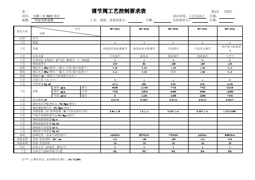
装置: 等温变换装置 工艺,系统,设备制表人: 日期 : 自控制表人: 日期:注***:1-操作状态,2-标准状态0℃,101.325kPa填写专业 序号名称 HV-0301HV-0302HV-0303PV-0301TIV-0301自控 位号 工艺 数量 111 1 1工艺 用途系统蒸汽添加量调节除氧水加水量调节汽包放空 汽包压力调节 一变炉进口温度调节 工艺 介质名称中压蒸汽除氧水 饱和蒸汽饱和蒸汽工艺气 工艺 介质状态 1-液体、2-气体、3-蒸汽、4、两相流 2 1 2 2 2 工艺 阀前温度℃236 98 196 196 180 系统 阀前压力MPa(绝压)(最大/正常/最小流量下) 3.30 3.50 1.30 1.30 2.15 系统 阀后压力MPa(绝压)(最大/正常/最小流量下) 2.15 2.50 常压 1.00 2.13 系统 阀阻比Sn (阀阻力与系统阻力之比) 工艺 计算工况(注 ***) 2 1 1 1 2 工艺 介质密度Kg/m316.51 961 6.61 6.61 18.04 工艺 流量 液体 kg/h 最大9860 15540 7788 7788 22320 蒸汽 kg/h 正常7220 12950 6490 6490 18600 气体 m3/h 最小0 5180 2596 2596 7440 工艺 动力粘度cP0.0170 0.2887 0.0154 0.0154 0.0247 工艺 液体热力学临界压力(Pc)Mpa(绝压) 工艺 液体饱和蒸汽压(Pv)Mpa(表压)工艺 压缩系数(Z)/绝热指数(K)(气体及蒸汽介质) 0.94/1.591.0/1.110.867/1.410.867/1.411.332/0.997工艺 气体介质饱和蒸汽压(Pv)Mpa(表压) 工艺 两相流液体流量Kg/h 工艺 两相流液体密度Kg/m3 工艺 两相流气体流量m3/h 工艺 两相流气体密度Kg/m3系统 检测位置(设备号或管线号) MS0302 BW0305 VT0308 LS0301 PG0304a 设备系统 设备/管道规格(DN )mm 125 100 100 125 350 设备系统 设备/管道材质20 20 20 20 20 自控 安装方式(1-垂直,2-水平) 2 2 2 2 2 工艺仪表空气故障时阀门位置FLFCFCFOFO装置: 等温变换装置 工艺,系统,设备制表人: 日期 : 自控制表人: 日期:注***:1-操作状态,2-标准状态0℃,101.325kPa填写专业 序号名称 TV-0302LV-0301LV-0302LV-0303自控 位号 工艺 数量 11 11工艺 用途增湿器水量调节汽包液位控制 脱盐水加液位控制气液分离器液位控制工艺 介质名称除氧水 除氧水 冷凝液 冷凝液 工艺 介质状态 1-液体、2-气体、3-蒸汽、4、两相流 1 1 1 1 工艺 阀前温度℃180 180 60 60 系统 阀前压力MPa(绝压)(最大/正常/最小流量下) 3.50 3.50 2.15 2.15 系统 阀后压力MPa(绝压)(最大/正常/最小流量下) 2.13 1.30 0.30 0.30 系统 阀阻比Sn (阀阻力与系统阻力之比) 工艺 计算工况(注 ***) 1 1 1 1 工艺 介质密度Kg/m3888.00 888.00 851.53 851.53 工艺 流量 液体 kg/h 最大7680 7980 1920 780 蒸汽 kg/h 正常6400 6650 1600 650 气体 m3/h 最小2560 2660 640 260 工艺 动力粘度cP0.1510 0.1510 0.2886 0.2886 工艺 液体热力学临界压力(Pc)Mpa(绝压) 工艺 液体饱和蒸汽压(Pv)Mpa(表压)工艺 压缩系数(Z)/绝热指数(K)(气体及蒸汽介质) 0.99/1.290.99/1.291.0/1.111.0/1.11工艺 气体介质饱和蒸汽压(Pv)Mpa(表压) 工艺 两相流液体流量Kg/h 工艺 两相流液体密度Kg/m3 工艺 两相流气体流量m3/h 工艺 两相流气体密度Kg/m3系统 检测位置(设备号或管线号) BW0303 BW0304 PL0301 PL003 设备系统 设备/管道规格(DN )mm 65 65 50 50 设备系统 设备/管道材质20 20 304L 304L 自控 安装方式(1-垂直,2-水平) 2 2 2 2 工艺仪表空气故障时阀门位置FLFLFOFO。
自控阀门目录ZL47F型自力式平衡阀ZL47F自力式平衡阀ZLF型自力式平衡阀ZYC型自力式压差控制阀ZZC、ZZV型自力式压力调节阀ZZC不锈钢自力式压力控制阀ZZWPE自力式电控温度调节阀ZZWP加热型自力温度调节阀ZZWP型自力式温度调节阀ZZYP自力式压力调节阀ZZY蒸汽型自力式压力控制阀电动型温度自力式调节阀-ZZWPE电动型温度自力式调节阀自力常开式减压阀-Y110自力常开式减压阀自力式减压阀-ZZYP自力式减压阀自力式压力调节阀-V230、V231自力式压力调节阀自力式压力调节阀-ZZYP自力式压力调节阀自力式压力调节阀-ZZY型自力式压力调节阀自力式压力调节阀ZZYP自力式压差控制阀-ZYC自力式压差控制阀自力式压差控制阀ZYC自力式差压调节阀-ZZV自力式差压调节阀自力式差压调节阀-ZZYW型自力式差压调节阀自力式带指挥器减压阀-ZZVYP自力式带指挥器减压阀自力式平衡阀-ZL47F自力式平衡阀自力式平衡阀自力式流量平衡阀-ZLF、ZL47F自力式流量平衡阀自力式流量控制平衡阀-ZL47F自力式流量控制平衡阀自力式温度调节阀-ZZWP自力式温度调节阀自力式电子温度调节阀自力式电控温度调节阀-ZZWPE型自力式电控温度调节阀自力式电控温度调节阀-ZZWPE自力式电控温度调节阀自力式自控流量调节阀ZL47F型自力式平衡阀一、产品[自力式平衡阀]的详细资料:产品型号:ZL47F-16型产品名称:自力式平衡阀产品特点:ZL47F-16型自力式平衡阀,主要是由一个自动调节阀瓣和手动调节阀瓣组成。
利用介质自身的压力变化为动力,自动调节各支管路流量的平衡,准确稳定流量,同时具有开度指示,锁定、关闭等功能。
适用于“供热、空调等非腐蚀性介质的流量控制。
运行前一次性调节,即可使系统流量自动恒定在要求的设定值。
二、主要技术参数:型号公称压力壳体试验压力使用介质介质温度ZL47F-16 1.6MPa 2.4MPa水、油等非腐蚀性液体0~100℃三、ZL47F型自力式平衡阀主要外型尺寸(法兰连接尺寸按GB4216):公称通径(mm)尺寸(mm)L H1H2151101227020110122702511513774321601829140200191147502151971476523020515480275259181100290268211125315334227150350357260200430407303250520452367300635486430350670555495订货须知:一、①ZL47F型自力式平衡阀产品名称与型号②ZL47F型自力式平衡阀口径③ZL47F型自力式平衡阀是否带附件二、若已经由设计单位选定公司的ZL47F型自力式平衡阀型号,请按ZL47F型自力式平衡阀型号三、当使用的场合非常重要或环境比较复杂时,请您尽量提供设计图纸和详细参数,相关产品:ZLF型自力式平衡阀数字锁定平衡阀KPF型平衡阀流量平衡阀法兰式平衡阀截止式流量平衡阀丝口平衡阀WM105型动态流量平衡阀WM115型动态流量平衡阀ZL47F自力式平衡阀一、产品[自立式平衡阀]的详细资料:产品型号:ZL47F产品名称:自立式平衡阀产品特点:ZL47F型自立式平衡阀,主要是由一个自动调节阀瓣和手动调节阀瓣组成。
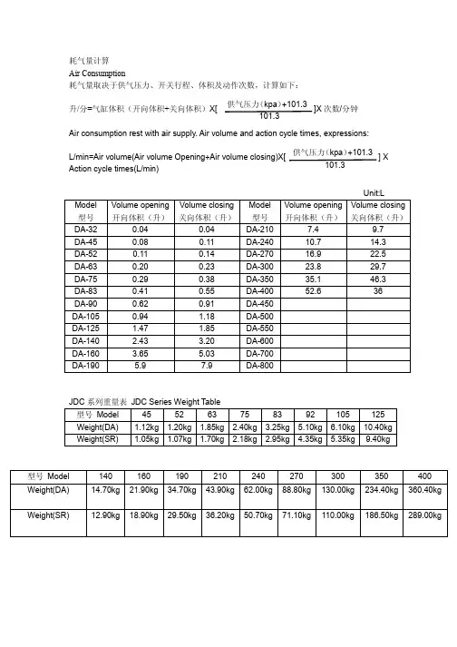
耗气量计算 Air Consumption 耗气量取决于供气压力、开关行程、体积及动作次数,计算如下: 升/分=气缸体积(开向体积+关向体积)X[ 供气压力 (kpa) +101.3 ]X 次数/分钟 101.3Air consumption rest with air supply. Air volume and action cycle times, expressions: L/min=Air volume(Air volume Opening+Air volume closing)X[ Action cycle times(L/min) 供气压力 (kpa) +101.3 ]X 101.3Unit:L Model 型号 DA-32 DA-45 DA-52 DA-63 DA-75 DA-83 DA-90 DA-105 DA-125 DA-140 DA-160 DA-190 Volume opening 开向体积(升) 0.04 0.08 0.11 0.20 0.29 0.41 0.62 0.94 1.47 2.43 3.65 5.9 Volume closing 关向体积(升) 0.04 0.11 0.14 0.23 0.38 0.55 0.91 1.18 1.85 3.20 5.03 7.9 Model 型号 DA-210 DA-240 DA-270 DA-300 DA-350 DA-400 DA-450 DA-500 DA-550 DA-600 DA-700 DA-800 Volume opening 开向体积(升) 7.4 10.7 16.9 23.8 35.1 52.6 Volume closing 关向体积(升) 9.7 14.3 22.5 29.7 46.3 36JDC 系列重量表 JDC Series Weight Table 型号 Model Weight(DA) Weight(SR) 45 1.12kg 1.05kg 52 1.20kg 1.07kg 63 1.85kg 1.70kg 75 2.40kg 2.18kg 83 3.25kg 2.95kg 92 5.10kg 4.35kg 105 6.10kg 5.35kg 125 10.40kg 9.40kg型号 Model Weight(DA) Weight(SR)140 14.70kg 12.90kg160 21.90kg 18.90kg190 34.70kg 29.50kg210 43.90kg 36.20kg240 62.00kg 50.70kg270 88.80kg 71.10kg300 130.00kg 110.00kg350 234.40kg 186.50kg400 360.40kg 289.00kg单作用执行器的选型 Sizing spring return actuators 在正常工作条件下,单作用执行器考虑的安全系数为 30%-50% 例如: 阀门需要力矩=80N.m 安全力矩=80(1+30%)=104N.m 气源压力=5Bar 对照单作用执行器输出力矩表,我们可以查到 SR140K7 输出力矩为 空气行程 0°=308N.m 空气行程 90°=247N.m 弹簧行程 90°=180N.m 弹簧行程 0°=120N.m 所有输出力矩均大于我们需求 注意: 单作用执行器弹簧复位过程中,执行器 B 口通气不影响执行器输出力矩,相反帮助弹簧的 复位。
Close-off pressures are variable and actuator dependent, consult Select Pro and/or Price Guide for specifics.ApplicationThese valves are designed to meet the needs of HVAC and commercial applications requiring bubble tight shut-off for liquids. Typical applications include chiller isolation, cooling tower isolation, change-over systems, large air handler coil control, bypass and process control applications. The large Cv values provide for an economical control valve solution for larger flow applications. Designed for use in Victaulic® piping systems.Jobsite NoteValve assembly should be stored in a weather protected area prior toinstallation. Reference the butterfly valve installation instruction for additional information.SY4-6A B C D E F 25.2” [640]22.8” [579]29.4” [747]24.4” [620]15.7” [399]7.8” [199]F7200VIC Technical Data SheetPressure Enhanced Rubber SeatD a t e c r e a t e d , 01/13/2020 - S u b j e c t t o c h a n g e . © B e l i m o A i r c o n t r o l s (U S A ), I n c .ApplicationSY Series actuators are fractional horsepower devices, and utilize full-wavepower supplies. Observe wire sizing and transformer sizing requirements.Proportional models CANNOT be connected to Belimo direct coupled (AF,AM, GM…etc) actuator power supplies or any type of half-wave device. YouMUST use a separate, dedicated transformer or power supply to power the SYactuator. Please do not connect other automation equipment to the dedicatedSY supply source. You MUST use four wires (plus a ground) to control aproportional control SY actuator (See SY Wiring Section).SY4-24MFT Technical Data SheetModulating, Non-Spring Return, 24 V, for DC 2...10 V or 4...20 mADatecreated,12/2/219-Subjecttochange.©BelimoAircontrols(USA),Inc.60Do not change sensitivity or dip switch setting with power applied. 61Power supply Common/Neutral and Control Signal “-”wiring to a common is prohibited. Terminals 4 and 6 need to be wired separately.62Isolation relays must be used in parallel connection of multipleactuators using a common control signal inputs. The relays should be DPDT.63Isolation relays are required in parallel applications. The reason parallel applications need isolation relays is that the motor uses two sets of windings, one for each direction. When one is energized to turn the actuator in a specific direction a voltage is generated in the other due to the magnetic field created from the first. It’s called back EMF. This is not an issue with one actuator because the voltage generated in the second winding isn’t connected to anything so there is no flow. On parallel applications without isolation, this EMF voltage energizes the winding it is connected to on the other actuators in the system, the actuators are tying to turn in both directions at once. The EMF voltage is always less than the supply voltage due to the resistance of the windings, so while the actuator still turns in the commanded direction, the drag from the other reduces the torque output and causes overheating.!WARNING! LIVE ELECTRICAL COMPONENTS!During installation, testing, servicing and troubleshooting of this product, it may be necessary to work with live electrical components. Have a qualified licensed electrician or other individual who has been properly trained in handling live electrical components perform these tasks. Failure to follow all electrical safety precautions when exposed to live electrical components could result in death or serious injury.SY4-24MFT Technical Data SheetModulating, Non-Spring Return, 24 V, for DC 2...10 V or 4...20 mAD a t e c r e a t e d , 12/20/2019 - S u b j e c t t o c h a n g e . © B e l i m o A i r c o n t r o l s (U S A ), I n c .。
特性控制阀,有基于传感器运行的流量控制, 2 通, 内螺纹, PN 25 (EPIV)• 额定电压 AC/DC 24 V • 控制 调节型, 交互式• 用于闭合的冷、热水系统• 用于供热通风系统中水侧的调节控制• 通过搏力谋 MP-Bus 或常规控制进行通信• 有源传感器信号的转换和切换触点型号概述型号DN Rp ["]V'nom [l/s]V'nom [l/min]V'nom [m³/h]kvs theor. [m³/h]PN EP015R+MP 151/20.3521 1.26 2.925EP020R+MP 203/40.6539 2.34 4.925EP025R+MP 251 1.1569 4.148.625EP032R+MP 321 1/4 1.8108 6.4814.225EP040R+MP 401 1/2 2.5150921.325EP050R+MP502 4.828817.2832.025理论kvs: 理论 kvs 值用于压降计算技术数据电气参数额定电压AC/DC 24 V 额定频率50/60 Hz额定电压范围AC 19.2...28.8 V / DC 21.6...28.8 V 运行功耗 3.5 W (DN 15, 20, 25)4.5 W (DN 32, 40, 50)保持功耗 1.3 W (DN 15, 20, 25)1.4 W (DN 32, 40, 50)变压器容量 6 VA (DN 15, 20, 25)7 VA (DN 32, 40, 50)连接方式接线 1 m, 4 x 0.75 mm²并联运行是(注意功耗)数据总线通信通讯协议MP-Bus节点数量MP-Bus 最多 8 个功能参数运行范围 Y 2...10 V 输入阻抗100 kΩ运行范围 Y 可调起点 0.5...24 V 终点 8.5...32 V 运行模式可选调节型 (DC 0...32 V)位置反馈信号U 2...10 V 位置反馈信号U 说明最大 1 mA 位置反馈信号U 可调起点 0.5...8 V 终点 2...10 V 电机噪音等级45 dB(A)可调节流量 V'max 30 ... 100%的Vnom控制精度±5% (V’nom 的25...100%)@20°C/ 不含乙二醇溶液控制精度注释±10% (V’nom 的25...100%)@-10...120°C/ 浓度为0...50%的乙二醇溶液最小可控流量V'nom 的 1%介质冷、热水,最大浓度50%的乙二醇溶液介质温度-10...120°C介质温度说明流体温度在-10...2°C 范围内时,推荐使用阀轴加热器或阀脖延伸件。
B213•ApplicationStainless Steel Ball and StemTechnical dataFunctional dataValve Size 0.5" [15]Fluidchilled or hot water, up to 60% glycol Fluid Temp Range (water)0...250°F [-18...120°C]Body Pressure Rating 600 psi Close-off pressure ∆ps 200 psiFlow characteristic equal percentage Servicing maintenance-free Flow Pattern 2-way Leakage rate0% for A – AB Controllable flow range 75°Cv4.7 Body pressure rating note 600 psiCv Flow RatingA-port: as stated in chart B-port: 70% of A – AB Cv MaterialsValve body Nickel-plated brass body Stem seal EPDM (lubricated)SeatPTFEPipe connection NPT female ends O-ring EPDM (lubricated)Ballstainless steel Suitable actuatorsNon-SpringTR LRB(X)NRSafety notesWARNING: This product can expose you to lead which is known to the State of California to cause cancer and reproductive harm. For more information go to Product featuresThis valve is typically used in air handling units on heating or cooling coils, and fan coil unit heating or cooling coils. Some other common applications include Unit Ventilators, VAV box re-heat coils and bypass loops. This valve is suitable for use in a hydronic system with variable flow.Flow/Mounting detailsB213 DimensionsDimensional drawingsLRB, LRXA B C D E F H1H29.4" [239] 2.4" [60] 5.6" [141] 5.0" [127] 1.3" [33] 1.3" [33] 1.2" [30] 1.1" [28]TRA B C D E F3.7" [95] 2.4" [60] 5.2" [132]4.6" [117] 1.3" [33] 1.3" [33]TFRB, TFRXA B C D E F7.9" [200] 2.4" [60] 6.1" [154] 5.5" [140] 1.8" [46] 1.8" [46]LFA B C D E F6.6" [167] 2.4" [60] 5.5" [139] 4.7" [120] 1.5" [39] 1.5" [39]ARB N4, ARX N4, NRB N4, NRX N4A B C D E F11.4" [289] 2.4" [60]7.7" [196]7.0" [179] 3.1" [80] 3.1" [80]B213TFRB, TFRXA B C D E F7.9" [200] 2.4" [60] 6.1" [154] 5.5" [140] 1.8" [46] 1.8" [46]ARB N4, ARX N4, NRB N4, NRX N4A B C D E F11.4" [289] 2.4" [60]7.7" [196]7.0" [179] 3.1" [80] 3.1" [80]LRX24-3•••••••On/Off, Floating Point, Non-Spring Return, 24 VTechnical dataElectrical dataNominal voltageAC/DC 24 V Nominal voltage frequency 50/60 Hz Power consumption in operation 1.5 W Power consumption in rest position 0.2 WTransformer sizing 2 VA (class 2 power source)Electrical Connection18 GA plenum cable with 1/2" conduit connector, degree of protection NEMA 2 / IP54, 3 ft [1 m] 10 ft [3 m] and 16ft [5 m]Overload Protectionelectronic thoughout 0...90° rotation Functional dataInput Impedance 600 ΩDirection of motion motor selectable with switch 0/1Manual override external push button Angle of rotation 90°Angle of rotation note adjustable with mechanical stop Running Time (Motor)90 s Noise level, motor 35 dB(A)Position indicationMechanically, pluggable Safety dataDegree of protection IEC/EN IP54Degree of protection NEMA/UL NEMA 2 UL Enclosure Type 2Agency Listing cULus acc. to UL60730-1A/-2-14, CAN/CSA E60730-1:02, CE acc. to 2014/30/EU Quality Standard ISO 9001Ambient temperature -22...122°F [-30...50°C]Storage temperature -40...176°F [-40...80°C]Ambient humidity max. 95% r.H., non-condensing Servicingmaintenance-free WeightWeight0.67 lb [0.30 kg]Safety notesCable for ZIP-RS232 US and ZIP-USB-MP US to Belimo gateways.Classic GM to GMB(X) retrofit bracket.Battery Back Up System for SY(7~10)-110120 to 24 VAC, 40 VA transformer.Cable for ZTH US to actuators w/o diagnostics socket.50% voltage divider kit (resistors with wires).PC Tool computer programming interface, serial port.Electrical installationLRX24-3INSTALLATION NOTESProvide overload protection and disconnect as required.Actuators may be connected in parallel. Power consumption and input impedance must be observed.Actuators may also be powered by 24 VDC.Actuators Hot wire must be connected to the control board common. Only connect common to neg. (-) legof control circuits. Terminal models (-T) have no-feedback.Actuators with plenum cable do not have numbers; use color codes instead.Meets cULus requirements without the need of an electrical ground connection.Warning! Live Electrical Components!During installation, testing, servicing and troubleshooting of this product, it may be necessary to workwith live electrical components. Have a qualified licensed electrician or other individual who has beenproperly trained in handling live electrical components perform these tasks. Failure to follow all electricalsafety precautions when exposed to live electrical components could result in death or serious injury.On/Off Floating PointFloating Point - Triac Source Floating Point - Triac Sink。
G220S-KType overviewType DNG220S-K20Technical dataFunctional data Valve Size0.75" [20]Fluid chilled or hot water, up to 60% glycol, steamFluid Temp Range (water)20...338°F [-7...170°C]Fluid Temp Range (steam)32...338°F [0...170°C]Body Pressure Rating ANSI Class 250, up to 400 psi below 150°FFlow characteristic modified equal percentageServicing repack kits availableRangeability Sv100:1Maximum differential pressure (water)50 psi [345 kPa]Max Differential Pressure (Steam)50 psi [345 kPa]Flow Pattern2-wayLeakage rate ANSI Class VIControllable flow range stem up - open A – ABCv7.5Maximum Inlet Pressure (Steam)100 psi [690 kPa]Materials Valve body BronzeValve plug Stainless steel AISI 316Spindle316 stainless steelSpindle seal EPDM O-ringSeat Stainless steel AISI 316Pipe connection NPT female endsSuitable actuators Non-Spring LVB(X)Spring LFElectrical fail-safe LVKB(X)G220S-K•••••Flow directionSafety notesWARNING: This product can expose you to lead which is known to the State of California to cause cancer and reproductive harm. For more information go to The valve has been designed for use in stationary heating, ventilation and air-conditioning systems and must not be used outside the specified field of application, especially in aircraft or in any other airborne means of transport.Only authorized specialists may carry out installation. All applicable legal or institutional installation regulations must be complied during installation.The valve does not contain any parts that can be replaced or repaired by the user.When determining the flow rate characteristic of controlled devices, the recognised directives must be observed.Installation notesThe direction of flow, specified by an arrow on the housing, is to be complied with, sinceotherwise the valve could become damaged.DimensionsDimensional drawingsLFType DN Weight [kg][kg]G220S-K200.9AB C D E F 7.9" [200]3.4" [86]9.7" [247]8.2" [208]1.2" [30] 4.9" [125]G220S-KLVA B C D E F8.6" [218] 3.4" [86]8.9" [226]7.4" [188] 1.9" [48] 1.9" [48]LVKA B C D E F9.7" [246] 3.4" [86]9.6" [244]8.1" [206] 1.9" [48] 1.9" [48]LVB24-SRModulating, Non-Spring Return, Linear, 24 V,for DC 2...10 V or 4...20 mATechnical dataElectrical data Nominal voltage AC/DC 24 VNominal voltage frequency50/60 HzPower consumption in operation 1 WPower consumption in rest position0.5 WTransformer sizing 2 VA (class 2 power source)Electrical Connection18 GA plenum cable, 3 ft [1 m], with 1/2"conduit connector, degree of protection NEMA2 / IP54Overload Protection electronic throughout full strokeElectrical Protection actuators are double insulatedFunctional data Actuating force motor500 N [115 lbf]Operating range Y 2...10 VOperating range Y note 4...20 mA w/ ZG-R01 (500 Ω, 1/4 W resistor)Input Impedance100 kΩ for 2...10 V (0.1 mA), 500 Ω for 4...20 mAPosition feedback U 2...10 VPosition feedback U note Max. 0.5 mADirection of motion motor selectable with switch 0/1Manual override 4 mm hex crank (shipped w/actuator)Stroke0.75" [19 mm]Running Time (Motor)default 90 s, variableNoise level, motor55 dB(A)Position indication Mechanically, with pointerSafety data Degree of protection IEC/EN IP54Degree of protection NEMA/UL NEMA 2Enclosure UL Enclosure Type 2Agency Listing cULus acc. to UL60730-1A/-2-14, CAN/CSAE60730-1:02, CE acc. to 2014/30/EU and2014/35/EUQuality Standard ISO 9001Ambient temperature-22...122°F [-30...50°C]Storage temperature-40...176°F [-40...80°C]Ambient humidity Max. 95% RH, non-condensingServicing maintenance-freeWeight Weight 2.43 lb [1.1 kg]Materials Housing material Die cast aluminium and plastic casing AccessoriesElectrical accessories Description TypeAuxiliary switch 2 x SPDT for NG GV Actuators S2A-GVLVB24-SR Electrical installationINSTALLATION NOTESActuators may also be powered by DC 24 V.Only connect common to negative (-) leg of control circuits.A 500 Ω resistor (ZG-R01) converts the 4...20 mA control signal to 2...10 V.Actuators with plenum cable do not have numbers; use color codes instead.Meets cULus requirements without the need of an electrical ground connection.Warning! Live electrical components!During installation, testing, servicing and troubleshooting of this product, it may be necessaryto work with live electrical components. Have a qualified licensed electrician or other individualwho has been properly trained in handling live electrical components perform these tasks.Failure to follow all electrical safety precautions when exposed to live electrical componentscould result in death or serious injury.Wiring diagramsVDC / 4 to 20 mADimensions。