SSAS 使用手册
- 格式:doc
- 大小:2.70 MB
- 文档页数:59
Testing Open Socket Communications Using PuTTYOctober 19, 2017Many instruments include the ability to be controlled via a remote connection to a computer using an Ethernet connection. In many cases, these instruments require a special software library that can help establish and maintain the communications link between the instrument and controlling computer. This can be annoying for a few reasons… the software library is likely to occupy a large amount of space on the controlling computer and is also required on any computer that is being used to control the instrument. In a remote networking application where multiple user’s may want access to a test instrument, this can cause support and installation headaches.Luckily, there are a few solutions that can help. In this application note, we are going to discuss using open socket communication techniques using an open source communication tool called PuTTY with a SIGLENT SSA3032X spectrum analyzer.What are open sockets and why use them?Within the context of Ethernet/LAN connections, sockets are like mailboxes. If you want to deliver information to a specific place, you need to be sure that your information is delivered to the correct address.In the context of test instrumentation, an open socket is a fixed address (or port number) on the Ethernet/LAN bus that is dedicated to process remote commands.Open sockets allow remote computers to simply use existing raw Ethernet connections for communications without having to add additional libraries (VISA or similar) that require additional storage space and processing overhead.Programs that utilize sockets for LAN communication tend to take up less memory and operate more quickly.PuTTYPuTTY is an open source software tool that provides a number of simple communication links (RAW, Telnet, SSSH, Serial, and others). It is available for free and there are a number of versions available for popular operating systems.You can download as well as learn more here: /In this example, we are using PuTTY to verify the raw LAN connection is working properly. It is quite a simple program that does not allow for very complex operation (sequences, converting data sets/strings, etc..). If you require more complex functionality, software platforms like Python, .NET, C#, LabVIEW, etc.. can be used to control the instrument using a similar open socket connection.ConfigurationIn this test, we are using the most current revision of the SIGLENT SSA3032X Spectrum Analyzer firmware(Revision 01.02.08.02) which enables open socket communication.This example also uses PuTTY version 0.67:Steps1. Install PuTTY for the OS you intend to use2. Make sure your instrument and firmware revision can use open socketsThe SSA3032X revision 01.02.08.02 enables open socket communication.To find the revision, press the System button > Sys Info.Figure 1 below shows a sample system information screen from a SIGLENT SSA3000X analyzer:Figure 1: Sample system information page from an SSA3000X.Check the product page and firmware release notes for more information.3. Connect the instrument to the local area using an Ethernet cable4. Find the IP address for the instrument. This is typically located in the System Information menu. On the SIGLENT SSA3032X, press the System button on the front panel > Interface > LAN.Figure 2 below shows a sample LAN setup page from a SIGLENT SSA3000X:Figure 2: Sample LAN information page from an SSA3000X.5. Open PuTTY6. Select Raw as connection type7. Enter the IP address in the Host Name field8. Enter the port number. This should be provided in the users or programming guide for the instrument. The SIGLENT SSA3000X uses port 5025.Figure 3 below shows the PuTTY configuration for this example:Figure 3: Example PuTTY configuration.9. Press Open. This will open a terminal window as shown in below:10. Using the computer keypad, enter *IDN? and press the Enter key on the keyboard to send the command.This is the standard command string that is used to request the identification string from the instrument. As shown below, the instrument responds with the manufacture, product ID, Serial Number, and firmware revision.ConclusionPuTTY is an easy way to verify an operational LAN connection to instrumentation that can use open sockets.North American Headquarters SIGLENT Technologies NA6557 Cochran Rd Solon, Ohio 44139Tel: 440-398-5800Toll Free:877-515-5551Fax: 440-399-1211****************/European Sales OfficesSIGLENT TECHNOLOGIES GERMANY GmbH Liebigstrasse 2-20, Gebaeude 14,22113 Hamburg GermanyTel: +49(0)40-819-95946Fax: +49(0)40-819-95947*******************Asian HeadquartersSIGLENT TECHNOLOGIES CO., LTD.Blog No.4 & No.5, Antongda Industrial Zone, 3rd Liuxian Road, Bao’an District, Shenzhen, 518101, China.Tel:+ 86 755 3661 5186Fax:+ 86 755 3359 1582*****************/ens。
Correction Information for "SSA Adapters User's Guide and Maintenance Information" SA-3272-02This procedure replaces MAP 2410 on page 13-49MAP 2410: SSA Repair VerificationThis MAP helps you to verify a repair after a FRU has been exchanged for a new one. Attention: Unless the using system needs to be switched off for some other reason, do not switch off the using system when servicing an SSA link or an enclosure in which SSA devices are installed. Enclosure power cables and external SSA cables that connect devices to the using system can be disconnected while that system is running.1. (from step 3 in MAP 2010: START; steps 3 and 5 in MAP 2320: SSA Link; step 3 in MAP 2323:SSA Intermittent Link Error; step 5 in "MAP 2324: SSA RAID" on page 13-30)Before you arrived at this MAP, you exchanged one or more FRUs for new FRUs. Some of those FRUs have Power lights (for example, disk drives and fan-and-power-supply assemblies). Checkwhether all those Power lights are on.Do all the FRUs that you have exchanged have their Power lights on (where applicable)?NO 1. Exchange, for a new one, the FRU whose Power light isoff.2. Go to step 2.YES Go to step 2.2. (from step 1)Are all Check lights off?NO Go to the START MAP for the enclosure in which thedevice that has its Check light on is installed.YES 1. Run diagnostics, in System Verification mode, to the devicethat reported the problem.Notes:1. Do not run Advanced Diagnostics; otherwise,errors are logged on other using systems that sharethe same loop.2. If you have just exchanged a disk drive or an SSAadapter, you might need to run cfgmgr to restore thedevice to the system configuration.2. If the original problem was not reported by a device,run diagnostics to each SSA adapter in the using system.3. Go to step 3.3. (from step 2)Do you still have the same SRN?NO Go to step 5.YES Go to step 4.4. (from step 3)Have you exchanged All the FRUs that were originally reported by the SRN?NO Exchange the next FRU listed for the SRN.YES 1. Run diagnostics, in System Verification mode, to all theadapters that are in this SSA loop.2. Run diagnostics, in System Verification mode, to all the diskdrives that are in this SSA loop.3. Run the Certify service aid (see "Certify Disk Service Aid"on page 12-18) to all the disk drives that are in this SSA loop.4. Correct all errors that are reported by the diagnostics.5. Go to step 65. (from step 3)Type smitty ssaraid and press Enter.Select Change/Show Use of an SSA Physical Disk.Are any disk drives listed as "SSA physical disks that are rejected"?NO Go to step 6.YES 1. Run diagnostics in System Verification mode to all the diskdrives that are listed as rejected.2. Run the Certify service aid (see"Certify Disk Service Aid"on page 12-18 ) to all the disk drives that are listed asrejected.3. If any problems occur, exchange the failed disk drives fornew disk drives (see "Exchanging Disk Drives" on page 10-1).4. Go to step 35 on page 13-48 to add the disk drive to thegroup of disk drives that are available for use by the RAIDmanager.Note:• A disk drive that is listed as rejected is notnecessarily failing. For example, the array mighthave rejected the disk drive because a powerproblem, or an SSA link problem, caused thatdrive to become temporarily unavailable. Undersuch conditions, the disk drive can be reused.•If you think that a disk drive has been rejectedbecause it is failing, check the error log history forthat disk drive. For example, if you suspectpdisk3, type on the command line:•ssa_ela -l pdisk3 -h 5•This command causes the error log for pdisk3 tobe analyzed for the previous five days. If aproblem is detected, an SRN is generated.6. (from step 3)Run the repair verification or repair completion procedures that are defined by your using system.If your subsystem contains RAID arrays, go to the RAID Checkout at 28 on page 13-45 of MAP 2324: SSA RAID.。
BI之SSAS完整实战教程1--开篇,BI简介SSAS简介⽂章提纲商业智能(BI, Business Intelligence)基本概念SSAS(SQL Server Analysis Services)相关⼯具(开发、管理和客户端)总结⼀、商业智能(BI, Business Intelligence)基本概念商业智能的概念在1996年最早由加特纳集团(Gartner Group)提出,加特纳集团将商业智能定义为:商业智能描述了⼀系列的概念和⽅法,通过应⽤基于事实的⽀持系统来辅助商业决策的制定。
商业智能技术提供使企业迅速分析数据的技术和⽅法,包括收集、管理和分析数据,将这些数据转化为有⽤的信息,然后分发到企业各处。
-- 以上摘⾃百度百科简⽽⾔之,商业智能是⼀个将数据转换为信息,进⽽发现信息中隐藏的知识,并将其应⽤于商业的过程。
以微软BI解决⽅案为例。
典型架构举例(以下⼤部分图⽚都来⾃于百度图⽚):我们可以将BI整体系统架构归纳为四个部分:数据源(关系数据库)à 数据仓库 à OLAP à 前端展现⼯具与之对应的,BI解决⽅案的相关产品模块我们对照产品看架构⽐较直观。
可以看到,BI解决⽅案⽐传统的报表⽅案更加强⼤的就是增加了OLAP组件。
-------------------------------------------------------------------------------补充背景知识:当今的数据处理⼤致可以分成两⼤类:联机事务处理OLTP(on-line transaction processing)、联机分析处理OLAP(On-Line Analytical Processing)。
OLTP是传统的关系型数据库的主要应⽤,主要是基本的、⽇常的事务处理,例如银⾏交易。
OLAP是数据仓库系统的主要应⽤,⽀持复杂的分析操作,侧重决策⽀持,并且提供直观易懂的查询结果。
UG506:Si82xx-EVBSi82XX E VALUATION B OARD U SER’S G UIDE1. IntroductionThe Si823x isolated driver family combines two independent isolated drivers into a single package. The Si8230/1/3/4 are high-side/low-side drivers, and the Si8232/5/6 are dual drivers. Versions with peak output currents of 0.5A (Si8230/1/2) and 4.0A (Si8233/4/5/6) are available. The Si8220/21 is a high-performance functional upgrade for opto-coupled drivers, such as the HCPL-3120 and the HPCL-0302 providing 2.5A of peak output current. These ISOdrivers utilize Skyworks' proprietary silicon isolation technology, which provides a choice of 2.5, 3.75, or 5.0kVrms withstand voltages. All drivers operate with a maximum output supply voltage of 24V. High integration, low propagation delay, small installed size, flexibility, and cost-effectiveness make the family ideal for a wide range of isolated MOSFET/IGBT gate drive applications.The Si82xx evaluation board allows designers to evaluate Skyworks’ family of ISOdrivers. The boards come populated with 5kVrms versions of the Si8220, Si8233, Si8234, and Si8235. The board includes land pads for common surface mount and through-hole packaged FET/IGBT power transistors. The board also includes patch area for additional prototyping that can be used to accommodate any load configuration a designer might need to evaluate. For more ISOdriver information, visit Skyworks web site at /products/isolation. The product data sheet and numerous application notes can be referenced to help facilitate designs.UG506:Si82xx-EVB2SkyworksSolutions,Inc.•Phone[781]376-3000•Fax[781]376-3100•*********************•2. Kit ContentsThe Si82xx Evaluation Kit contains the following items:⏹ Si82xx-based evaluation board (Si82xx-EVB) shown in Figure1.⏹ Si8220, Opto-input,2.5A, 5kV ISOdriver ⏹ Si8233, 2-input, 4A, 5kV, High-Side/Low-Side ISOdriver ⏹ Si8234, PWM-input, 4A, 5kV High-Side/Low-Side ISOdriver ⏹ Si8235, 2-input, 4A, 5kV Dual ISOdriverFigure 1.Si82xx Evaluation Board OverviewUG506:Si82xx-EVB 3. Si82xx ISOdriver Board OverviewThe Si82xx evaluation board is populated with the following ISOdrivers:⏹ Si8220 in wide-body SOIC-16 package, opto-input, 2.5A, 5kV ISOdriver⏹ Si8233 in wide-body SOIC-16 package, 2-input, 4A, 5kV High-Side/Low-Side ISOdriver⏹ Si8234 in wide-body SOIC-16 package, PWM-input, 4A, 5kV High-Side/Low-Side ISOdriver⏹ Si8235 in wide-body SOIC-16 package, 2-input, 4A, 5kV Dual ISOdriver⏹ High-side and low-side land pads for surface mount packaged FET/IGBT power transistors (not populated)⏹ High-side and low-side land pads for through-hole packaged FET/IGBT power transistors (not populated)⏹ Patch areaThe Si82xx board is four separate evaluation boards in one, with each section featuring a different ISOdriver (Si8220, Si8233, Si8234, or Si8235). Each section is isolated from the other sections and requires its own power supplies to power the given section's ISOdriver. Each section's ISOdriver is designed to be powered separately with input supplies for VDDI (5.5V, 500mA) and output supplies for VDDA, VDDB, or VDD up to 24V. The user is expected to connect their desired drive-trane topology and load to the outputs of the appropriate ISOdriver and the patch area. Figure2 shows a silkscreen overview of the board.Please note the voltage rating for the prepopulated components in the Si82xx BOM section of this document before applying power to the ISOdriver and customer specific driver-trane. Applying a voltage to a component that is higher than its rating can cause permanent device damage. If the install components do not meet the user's requirements, these components need to be replaced before proceeding. Moreover, if a user wants to evaluate an ISOdriver in a wide-body package other than the ones populated, this can be accomplished by removing the footprint-compatible device installed on the evaluation board and replacing it with the desired footprint-compatible ISOdriver.SkyworksSolutions,Inc.•Phone[781]376-3000•Fax[781]376-3100•*********************•3UG506:Si82xx-EVB4SkyworksSolutions,Inc.•Phone[781]376-3000•Fax[781]376-3100•*********************•Figure 2.Si82xx Evaluation Board SilkscreenUG506:Si82xx-EVBSkyworksSolutions,Inc.•Phone[781]376-3000•Fax[781]376-3100•*********************• 53.1. Si82xx ISOdriver Board TestFigure 3 illustrates the Si8234 with VDDI powered from 5V and VDDA and VDDB powered from 15V. A 10kHz signal is applied to the Si8234's PWM input. As shown, the Si8234 transmits a 10kHz signal to VOA and VOB (Channel 3 illustrates VOA output, and Channel 2 illustrates VOB output). Note that VOA and VOB are 180° out of phase, as would be expected of a PWM driver. In this setup, no drive-trane was connected to the outputs (VOA and VOB) of the Si8234. Nevertheless, the potentiometer, R35, can be adjusted to dynamically change the dead-time of the Si8234 if desired. Duplicating this setup is an excellent test to become familiar with the evaluation board. To repeat this test, perform the following steps:1.Install a shunting jumper to J12 (Position 1, 2).2.Install a shunting jumper to J14.3.Install a shunting jumper to J11.4.Install a shunting jumper to J13.5.Connect a 5Vp-p square wave to P7.6.Connect a 5V (100mA) supply to P9.7.Connect a 15V (100mA) supply to P14.8.Connect a 15V (100mA) supply to P15.9.Connect a scope probe to TP9 to view VOA.10.Connect a scope probe to TP11 to view VOB.Figure 3.Si8234 PWM OutputsUG506:Si82xx-EVB6SkyworksSolutions,Inc.•Phone[781]376-3000•Fax[781]376-3100•*********************•4. Si82xx Evaluation Board SchematicsFigure 4.Si82xx Evaluation Board Schematic (1 of 4)UG506:Si82xx-EVBSkyworksSolutions,Inc.•Phone[781]376-3000•Fax[781]376-3100•*********************• 7Figure 5.Si82xx Evaluation Board Schematic (2 of 4)UG506:Si82xx-EVB8SkyworksSolutions,Inc.•Phone[781]376-3000•Fax[781]376-3100•*********************•Figure 6.Si82xx Evaluation Board Schematic (3 of 4)UG506:Si82xx-EVBSkyworksSolutions,Inc.•Phone[781]376-3000•Fax[781]376-3100•*********************• 9Figure 7.Si82xx Evaluation Board Schematic (4 of 4)UG506:Si82xx-EVB10SkyworksSolutions,Inc.•Phone[781]376-3000•Fax[781]376-3100•*********************• 5. Si82xx Evaluation Board LayoutFigure 8.Si82xx Top LayerFigure9.Si82xx Bottom Layer6. Bill of MaterialsTable 1. Si82xx-EVB Bill of MaterialsItem Qty Ref Part Number Mfr Description110C1,C4–5,C8–9, C12,C22, C24,C26, C28311-1140-2-ND Digikey Cap, 0.1µF, X7R, Ceramic, 50V, 0805,±10%, or eq, RoHS22C7, C11PCC2249CT-ND Digikey Cap 1.0µF, X5R, Ceramic, 0805, 16V,±10%, or eq, RoHS31C3 PCC1893CT-ND Digikey Cap 1.0µF, X7R, Ceramic, 1206, 25V,±10%, or eq, RoHS43C2, C6, C20 490-1809-1-ND Digikey Cap 4.7µF, X7R, Ceramic, 1206, 25V,±10%, or eq, RoHS54C23, C25,C27, C29490-1809-1-ND Digikey Cap 4.7µF, X7R, Ceramic, 1206, 25V,±10%, or eq, RoHS, no-pop67C10,C14–19CAP 0805Digikey Cap, NO POP, 0805, or eq, RoHS77Q3–4,Q7–8,Q11–12,Q15D2-PAK-NO-POP D2-pak-no-pop D2-PAK-NO-POP or eq, RoHS84D1–3, D7US1K-FDICT-ND Digikey Diode, SW ULT FAST, 1A, 800V, SMA,RoHS925J2–7, J9–11, J13–17,J19–25,J56–57,J74–75S1011E-02-ND Digikey Stake Header, 1X2, 0.1"CTR, Gold,or eq, RoHS10112J26–55,J58–73,J76–78,J80–139,J168–169,J171NO-POP None No-pop, RoHS114J1, J8, J12,J18S2011E-02-ND Digikey Stake Header, 2X2, 0.1"CTR, Gold, OREq, RoHS122R23, R3592W-104LF-ND Digikey Pot, 100kΩ, Res, 3/8" SQ CERM SL,MT, TOP ADJ, ±10%, OR EQ, RoHS 131R42P100ACT-ND Digikey Res, 100Ω, SMT, 0805, 1/8W, ±5%, OREQ, RoHS143R1, R12, R24P10.0KCCT-ND Digikey Res, 10.0k Ω, SMT, 0805, 1/8W,±1%, or eq, RoHS 151R39311-237CRCT-ND Digikey Res 237Ω, SMT, 0805, 1/8W,±1%, or eq, RoHS 161R41311-330ARCT-ND Digikey Res, 330Ω, SMT, 0805, 1/8W,±5%, or eq, RoHS 175R9, R11, R20, R22, R32RHM470ACT-NDDigikeyRes, 470Ω, SMT, 0805, 1/8W,±5%, or eq, RoHS 186R8, R10, R19, R21, R31, R40P49.9CCT-ND DigikeyRes, 49.9Ω, SMT, 0805, 1/8W,±1%, or eq 1921R2–7, R13–18, R25–30, R36–38NO POP DigikeyRes, no pop, SMT, 0805, or eq, RoHS201U4Si8220BD-D-IS Skyworks IC, 2.5A, 5kV, ISOdrivers with OptoInput, RoHS 211U2Si8233BD-D-IS Skyworks 4.0A, 5kV, ISOdrivers, RoHS 221U3Si8234BD-D-IS Skyworks IC, 4.0A, 5kV, ISOdrivers, RoHS 231U1Si8235BD-D-IS Skyworks IC, 4.0A, 5kV, ISOdrivers, RoHS 244RF1–4SJ5744-0-ND Digikey Bumpon protective, bumper, Silicone, oreq, RoHS 2514TP1–11, TP13, TP15–16No PopDigikeyTest point, PC compact, no pop, or eq,RoHS267Q1–2, Q5–6, Q9–10, Q13TO220-NO-POP To220-no-popTO220-no-pop, or eq, RoHS2713P2–3, P5–15277-1236-ND Digikey Conn Term Block, 5.08mm ctrs, PCB,2 POS, RoHS 282P1, P4 277-1249-ND Digikey Conn Term Block, 5.08mm ctrs, PCB,4 POS, RoHS291Q14ZXM61N02FCT-NDDigikeyMosfet, N-Chan, 20V, 1.7A,SOT23-3, RoHSTable 1. Si82xx-EVB Bill of Materials (Continued)Item Qty Ref Part Number Mfr Description7. Ordering GuideTable 2. Si82xx Evaluation Board Ordering Guide Ordering Part Number (OPN)DescriptionSi82xx-KIT Si82xx CMOS ISOdriver evaluation board kitN OTES:Replace this page in the pdf version of this datasheet with the Skyworks copyright page(skyworks_lastpage_general.pdf).。
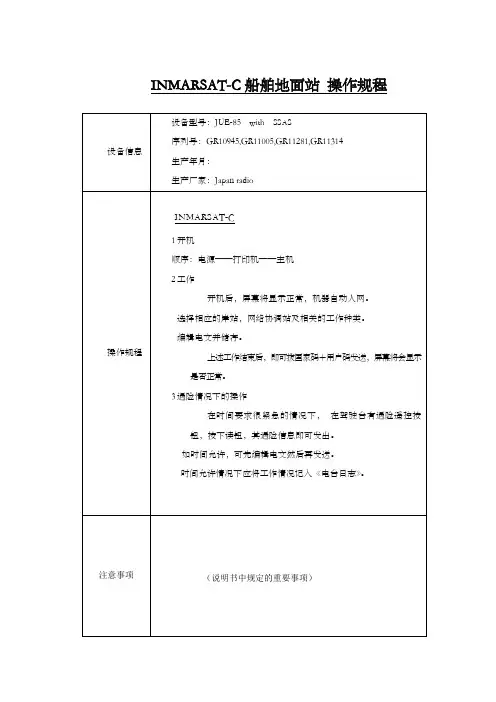
INMARSAT-C船舶地面站操作规程
INMARSAT船舶地面站操作规程
中/高频/SSB无线电装置操作规程
甚高频无线电装置操作规程
高频无线电装置操作规程
NVATEX航行警告接收机操作规程
气象传真机操作规程
AIS船用全球自动识别系统操作规程
回声测深仪操作规程
GPS接收机操作规程
自动操舵仪操作规程
电罗经操作规程
磁罗经操作规程
电磁记程仪操作规程
VDR船载航行数据记录仪操作规程
操作规程
注意事项备注
双向无线电话操作规程
SART 操作规程
EPIRB 操作规程
INMARSAT-F 操作规程
RADAR 雷达操作规程
RADAR雷达操作规程
雷达操作规程
舵机操作程序
1、通知机舱舵机供电。
2、打开舵机开关,选择舵机组。
3、选择操纵方式,随动方式。
4、转动舵轮试验舵角指示。
5、最后舵角指示回零。
6、舵机备好。
应急舵操作规程。

JUE-95SAInmarsat C SSASComplies with latest IMOregulations according toMSC.136(76) / MSC.144(17)– JRC introduces a highly reliable SSAS system recognised for its unique role in the maritime safetyCompact antenna designEasy installationBuilt-in GPS receiverLow cost of ownershipFully meets IMO requirements for SSASsince 1915JUE-95SA Inmarsat C SSAS – performance featuresThe JUE-95SA is a small, lightweight and highlyreliable terminal, recognised for its unique role inmaritime safety and plays an integral part in thesafety of live at sea.Unique featuresShip Security Alert Systems (SSAS) is a system that contributes to the IMO’sefforts to strengthen maritime security and suppress acts of terrorismand piracy against shipping. In case of attempted piracy or terrorism, thevessel’s SSAS function can be activated and appropriate law-enforcementor military forces can be alerted.About SSASJRC has developed a compact, mobile satellite communication system.The JUE-95SA Inmarsat C SSAS utilises two-way data/messagingcommunications anywhere in the world. New IMO requirements statetwo security alarm buttons must be provided. These are located discreetlyon the vessel and can be activated in case of piracy or terrorist attack. Itwill allow covert activation which transmits an alert signal from vessel toshore, alerting the appropriate authority that the security of the vessel isunder threat or has been compromised. The SSAS system will not raise thealert onboard the vessel, nor alert any other ships.If vessels have older Inmarsat C systems onboard, you can simply installJRC’s JUE-95SA in order to comply with current SOLAS regulations.Compact solutionJRC has been providing sales and support of products since 1915. Today, JRC offers comprehensive assistance through its organisation, in partnership with a worldwide StarNetwork™ of over 270 fully trained and qualified partners and agents, assisting you 24 hours a day, 7 days a week and 365 days a year.JRC StarNetwork™JUE-95SA Inmarsat C SSAS – system flexibilityJRC’s mobile JUE-95SA terminal incorporates various self-diagnostic programmes to facilitate maintenance and troubleshooting, reporting any possible problems it might suffer. Theresults are displayed on the data terminal. These functions will allow for easy maintenanceand more reliability. In addition, automatic testing for performance verification and commissioning via the satellite channel is also available.Self diagnosisJCmail, a freeware application developed by JRC, enables you totransmit and receive email messages very easily on your PC.In addition, this programme allows you to receive EnhancedGroup Calling (EGC) messages. EGC enables authorisedinformation providers to broadcast international safety andcommercial service message to selected group of ships.JCmailThe JUE-95SA system has the same cable management philosophy resembling all other Inmarsat products that JRC is offering, allowing for an easy installation as only a single coax cable is used between antenna and terminal. Both are very compact and can be easily installed on any size and type of vessel.Flexible installationJUE-95SA Inmarsat C SSAS – specificationsModelJUE-95SA IMO type approved Class of Inmarsat C MES Class 1Terminal and antennaModel – terminal NTF-782SAModel – antenna NAF-742SA (including pole mounting bracket)FrequencyTX 1626.5MHz - 1646.5MHz RX 1530.0MHz - 1545.0MHz GPS 1575.2 MHz ±1MHzChannel spacing 5KHzG/T -23.7dB/K minimum at 5º angleE.I.R.P .+7 to +16dBWModulation TX and RX: 1200 symbols/sec BPSKData rate TX: 600bps RX: 600bps Antennatype: helical pattern: hemispherepolarisation: right hand circularPower supply voltage DC 24V (+30% -20%) Power consumption TX 75W, RX 25W Ambient conditionantenna: -35°C +55°C terminal: -15°C +55°CPreservation temperature -40°C +80°C Relative humidity +40ºC up to 95% Icingup to 25mm (antenna)Precipitation 100mm/hour (antenna)Wind up to 100 knots Vibrationas specified by InmarsatOptional itemsPower supply unit (AC/DC)NBD-577CFor further information please contact:All specifications are subject to change without notification.1. Antenna2. Terminal3. Security buttons (2)4. Cables5. Pole mounting bracket6. Spare parts7. Manual (English)8. SSAS setup tool (CD-ROM)Which cables? Antenna to terminal 30 m Power cable to terminal 2 m Security button to terminal (2)5 mWhat’s standard in the box?Copyright © 2007 JRC -07.12/20/1JRCCessnalaan 40-421119 NL, Schiphol-Rijk, The Netherlands T F E W +31 20 6 580 750+31 20 6 580 755sales@ 。

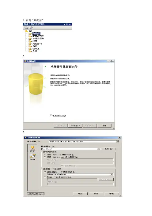
1 右击“数据源”
2
3
4 确定之后点击“下一步”,
5 Provider=SQLNCLI.1;Data Source=localhost;Integrated Security=SSPI;Initial Catalog=AdventureWorksDW
6 点击“完成”,再在解决方案资源管理器中,新建数据源视图
7 选择建好的数据源,点击“下一步”
8
9 点击“下一步”
10 点击“完成”,星型图
11在解决方案资源管理器中,新建多维数据集,点击“下一步”
12
13
14
15 在“时间维度表”下拉列表中选择……
16 设置,点击“下一步”
17 可设置度量值名,“下一步”
18
19 可根据需要去掉部分维度属性,点击“下一步”
20 点击“完成”
21
22点击左下“层次结构”“Due Date”的“编辑Dim Time”,其它的亦如此。
据库选项,将其改为“Analysis Services”点击“确定”
24右击解决方案资源管理器中项目名称,选择“部署”,右下会显示
25双击解决方案资源管理器中的多维数据集下的数据集,选择“浏览器”选项卡。
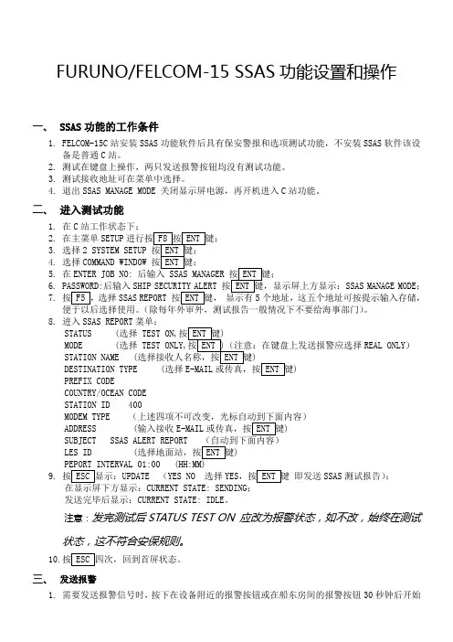
FURUNO/FELCOM-15 SSAS功能设置和操作一、 SSAS功能的工作条件1.FELCOM-15C站安装SSAS功能软件后具有保安警报和选项测试功能,不安装SSAS软件该设备是普通C站。
2.测试在键盘上操作,两只发送报警按钮均没有测试功能。
3.测试接收地址可在菜单中选择。
4.退出SSAS MANAGE MODE 关闭显示屏电源,再开机进入C站功能。
二、进入测试功能1.在C站工作状态下;2.在主菜单SETUP3.选择2 SYSTEM SETUP4.选择COMMAND WINDOW5.在ENTER JOB NO:6.后输入SHIP SSAS MANAGE MODE;7.选择SSAS REPORT 这五个地址可按提示输入存储,。
8.进入SSAS REPORT菜单:STATUS (选择 TEST ON,MODE (选择REAL ONLY)STATION NAME (DESTINATION TYPE (选择)PREFIX CODECOUNTRY/OCEAN CODESTATION ID 400MODEM TYPEADDRESS (输入接收E-MAIL)LES ID ()9.UPDATE (YES NO 选择YES即发送SSAS测试报告);CURRENT STATE: SENDING发送完毕后显示:CURRENT STATE: IDLE。
注意:发完测试后STATUS TEST ON 应改为报警状态,如不改,始终在测试状态,这不符合安保规则。
10.三、发送报警1.需要发送报警信号时,按下在设备附近的报警按钮或在船东房间的报警按钮30秒钟后开始发送报警信号。
2.停止发送报警信号,再按一下报警按钮,使按钮弹起。
在显示屏上显示:SSAS UNIT ACTIATIONHAS BEEN CANCELED。
四、防止误报警1.当不小心无意中按下报警按钮或误操作了,应立即多次按下报警按钮,OFF-ON-OFF-ON-OFF能看到显示屏上显示:SSAS UNIT ACTIATION HAS BEEN CANCELED字样,说明误发送已被停止。
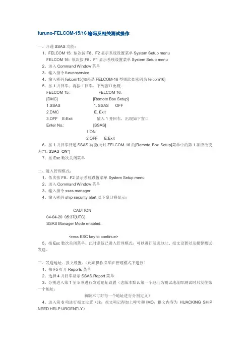
furuno-FELCOM-15/16输码及相关测试操作一、开通SSAS功能:1、FELCOM 15: 依次按F8、F2显示系统设置菜单System Setup menuFELCOM 16: 依次按F8、F1显示系统设置菜单System Setup menu2、进入Command Window菜单3、输入指令furunoservice4、输入密码felcom15(如果是FELCOM-16型则此处密码为felcom16)5、按1并回车;再按1回车。
下列窗口出现:FELCOM 15: FELCOM 16:[DMC] [Remote Box Setup]1.SSAS 1. SSAS OFF2.DMC E. Exit3.OFF E:Exit 输入1并回车,出现如下窗口Enter No.: [SSAS]1.ON2.OFF E:Exit6、按1并回车开通SSAS功能(此时FELCOM 16的[Remote Box Setup]菜单中的第1项应改变为:“1. SSAS ON”)7、按Esc数次关闭菜单二、进入管理模式:1、依次按F8、F2显示系统设置菜单System Setup menu2、进入Command Window菜单3、输入指令ssas manager4、输入密码ship security alert以下窗口将显示:CAUTION04-04-20 05:37(UTC)SSAS Manager Mode enabled.<ress ESC key to continue>5、按Esc数次关闭菜单。
此时系统已进入管理模式,可以进行发送地址、报文设置以及报警测试发送。
三、发送地址、报文设置:(此项操作必须在管理模式下进行)1、按F5打开Reports菜单2、选择4并回车显示SSAS Report菜单3、分别进入第1至5项进行发送地址设置(老版本默认第一个地址为测试地址即测试时只发往第一个地址;新版本可对每一个地址进行分别定义)4、进入第6项进行报文设置(注:报文项记得加上呼号和IMO,报文内容为HIJACKING SHIP NEED HELP URGENTLY)四、发送报警1、打开SSAS报警按钮保护盖2、按下按钮3、SSAS报警信息在按钮按下30秒种后开始自动发送注意:如果是意外按下报警按钮,可在30秒钟内再次按一下按钮取消报警发送,此时会出现提示信息“INF:SSAS UNIT activation has been canceled.”如果是FELCOM16型则是通信单元的POWER指示灯闪30秒。
EXS SSA 用户指南第一章、安装本节包含了安装和运行SSA(SwitchSight Administrator)应用的一些信息。
在本章中:-------------------------------------------------------------------------------------------------·SSA安装指南:Windows NT·与交换机连接·SSA 用户接口-------------------------------------------------------------------------------------------------SSA 安装指南:Windows NT以系统管理员登录到你的目标机器:1.插入EXS SwitchKit CD.2.安装SSA,双击目录Switch\User Interfaces中SSA.EXE。
3.这是一个自解压的可执行文件。
所有相关文件被放在缺省的目录c:\ProgramFiles\Excel Switching Corporation\SSA 中。
4.根据屏幕指导安装。
5.当提示重启动时重启动计算机。
6.点击目录c:\ProgramFiles\Excel Switching Corporation\SSA中SSA.EXE,启动SSA 的应用程序。
注:SSA 应运行在与其它EXS SwitchKit模块及呼叫控制应用不同的计算机上。
之所以这样推荐是希望为实时处理提供一个独特的应用环境,它应独立于其它任何图形显示环境。
参看EXS SwitchKit 安装和用户指南有关其它SwitchKit 部件。
与交换机连接第一次运行SSA,你必须与交换机建立连接。
为了进入连接至交换机窗口(图1.1),从主菜单中选择File/Connect/Create,输入下面的信息。
交换机标志(Label of the Switch)识别交换机的任一名字主机名(Host Name)LLC 的IP 地址端口地址(Port Address)LLC的端口地址注:当你关闭SSA下次重新启动SSA时,SSA 会自动提示你连接前次的LLC。
Installation & Service InstructionsIS-SSA75/SSA105Auto Pilot Soft Start Valve1/4", 3/8" & 1/2" SSA75 &3/8", 1/2" & 3/4" SSA105ISSUED: February, 2005Doc. #ISSSA75105, ECN #050142, Rev. 1IntroductionFollow these instructions when installing, operating, or servicingthe product.Application LimitsThese products are intended for use in general-purpose compressedair systems only. These units should not be used as shut-off valves,as they do not shut off completely and must always be placed aftera shut-off valve.Operating Pressure:kPa PSIG barMaximum Inlet Pressure103515010.0Minimum Inlet Pressure21030 2.0Ambient Temperature Range: 4°C to 54°C (40°F to 130°F)SymbolInstallationThe Auto-Pilot Soft Start valves should be installed with reasonableaccessibility for service and adjusting needle valve with a screwdriver.Keep pipe or tubing lengths to a minimum with inside clean and freeof dirt and chips. Pipe joint compound should be used sparinglyand applied only to the male pipe – never into the female port. Donot use PTFE tape to seal pipe joints – pieces have a tendency tobreak off and lodge inside the unit, possibly causing malfunction.Care should be taken to avoid undue strain on valve.Air applied to the valve must be filtered with a 40 micron filter torealize maximum component life.Life Expectancy-Normal multi-million cycle life expectancy ofthese valves is based on the use of properly filtered and lubricatedair at room temperature. These valves are also designed to operateunder non-lubricated conditions and will yield millions of maintenancefree cycles.Factory Pre-Lubrication -Valves are pre-lubricated at assemblywith a petroleum based grease which has a lithium content.In-Service Lubrication-I n-service lubrication is not required;however, if lubrication is to be used, F442 oil is recommended. Thisoil is specially formulated to provide peak performance andmaximum service life from all air operated equipment. Otherwise,use an air line lubricant (compatible with Nitrile & Polyurethaneseals) which will readily atomize and be of the medium aniline type.Aniline point range must be between 180° and 220°F.Viscosity at 100°F: 140 - 170 SUS.!CAUTION: Do not use synthetic, reconstituted, or oils withan alcohol content or detergent additive.!CAUTION:Do not restrict the inlet of valves having aninternal pilot supply. Pressure supply piping must be thesame size as the inlet port or larger to insure that the pilotvalve receives sufficient pressure supply during high flowconditions.FunctionWhen pressure is supplied to the inlet port, gradual filling of thedownstream system occurs through the adjustable needle valve.Upon reaching 70% of the supply pressure, the valve switches frommetered flow to full flow. The ramp up time to reach 70% of supplypressure is adjustable via the needle valve in the cover(See Figure 1).!WARNINGTo avoid unpredictable system behavior that can cause personal injuryand property damage:•Disconnect electrical supply (when necessary) before installation,servicing, or conversion.•Disconnect air supply and depressurize all air lines connected tothis product before installation, servicing, or conversion.•Operate within the manufacturer’s specified pressure, temperature,and other conditions listed in these instructions.•Medium must be moisture-free if ambient temperature is belowfreezing.•Service according to procedures listed in these instructions.•Installation, service, and conversion of these products must beperformed by knowledgeable personnel who understand howpneumatic products are to be applied.•After installation, servicing, or conversion, air and electricalsupplies (when necessary) should be connected and the producttested for proper function and leakage. If audible leakage is present,or the product does not operate properly, do not put into use.•Warnings and specifications on the product should not be coveredby paint, etc. If masking is not possible, contact your localrepresentative for replacement labels.!WARNINGFAILURE OR IMPROPER SELECTION OR IMPROPER USE OFTHE PRODUCTS AND/OR SYSTEMS DESCRIBED HEREIN ORRELATED ITEMS CAN CAUSE DEATH, PERSONAL INJURY ANDPROPERTY DAMAGE.This document and other information from The Company, itssubsidiaries and authorized distributors provide product and/or systemoptions for further investigation by users having technical expertise. Itis important that you analyze all aspects of your application, includingconsequences of any failure and review the information concerningthe product or systems in the current product catalog. Due to thevariety of operating conditions and applications for these products orsystems, the user, through its own analysis and testing, is solelyresponsible for making the final selection of the products and systemsand assuring that all performance, safety and warning requirementsof the application are met.The products described herein, including without limitation, productfeatures, specifications, designs, availability and pricing, are subject tochange by The Company and its subsidiaries at any time without notice.EXTRA COPIES OF THESE INSTRUCTIONS ARE AVAILABLE FORINCLUSION IN EQUIPMENT / MAINTENANCE MANUALS THAT UTILIZETHESE PRODUCTS. CONTACT YOUR LOCAL REPRESENTATIVE. Pneumatic DivisionRichland, Michigan 49083269-629-5000Auto Pilot Soft Start Valve 1/4", 3/8" & 1/2" SSA75 & 3/8", 1/2" & 3/4" SSA105IS-SSA75/SSA105SSA75SSA105Figure 3Dimensions:SSA75SSA105SSA75SSA105Figure 1Adjustment Figure 2Lockout Pin RemovalININScrewAdjustmentThe filling speed and pressurization of downstream circuit is accomplished by a Needle Valve located in the Cover (See Figure 1). Adjustment is performed using a standard flat blade screwdriver as indicated in Figure 1. Adjustments can be made by performing start-up test and adjusting the Needle Valve from zero to a maximum of 4 turns open until desired equipment speed is reached.!Caution: Do not turn needle valve more than 4 turns out from closed position as it is a pressure circuit and could blow out with force.The adjustment of the initial airflow rate into the downstream side of the soft-start valve is done with the Needle Valve. Turning Needle Valve counterclockwise will decrease amount of time to fill downstream circuit. Turning Needle Valve clockwise will increase amount of time to fill downstream circuit.Once the desired start-up speed of the downstream circuit has been reached, the adjustment area can be blocked off to prevent tampering by inserting the Lockout Pin provided in the package.Any further adjustments will require the removal of the Lockout Pin as shown in Figure 2.Service!Caution: Disconnect or shut off air supply and exhaust pressure before servicing unit.!Caution: Grease packets are supplied with kits for lubrication of seals. Use only mineral based grease or oils. Do not use synthetic oils such as esters. Do not use silicones.Note:After servicing unit, turn on air supply and check for leaks.If leakage occurs, do not operate – conduct repairs and retest.Note :Items marked with an * are included in the service kit.1.Remove the four Screws that retain the Cover and remove Cover.Next remove Plunger with Seals from Body.2.Remove Bottom Plug by unscrewing it from the Body. Next remove Bottom Spring, Disc Holder Assembly and Gasket.3.Clean, and carefully inspect parts for wear and / or damage.If replacement is necessary, use parts from service kit.4.Lubricate O-rings and U-cup with grease (supplied with kit).5.Install Gasket into Body. Then install Disc Holder, Bottom Spring and Bottom Plug in to Body. See Figure 3 for torque value.6.Install Punger with Seals into the Body. Install two O-rings between Body and Cover (make sure air passages are aligned properly),install four Screws and tighten per Figure 3.Service Kits Available:Description SSA75SSA105Service KitRKSS75RKSS105There may be extra parts in the kit.ModelPort ABCDEFSizeSSA753/8" 2.19 4.72 2.06 1.50 1.66.72(56)(120)(52)(38)(42)(18)SSA1051/2"3.03 5.25 2.75 1.84 2.53.84(77)(133)(70)(47)(64)(21)Inches (mm)。
SSAS 教程第 1 课:在 Analysis Services 项目中定义数据源视图本课程包含以下任务:创建 Analysis Services 项目在本任务中,将基于 Analysis Services 模板创建 Analysis Services Tutorial 项目。
定义数据源在本任务中,将 AdventureWorks2008R2 DW 数据库定义为将在后续课程中定义的 Analysis Services 维度和多维数据集的数据源。
定义数据源视图在本任务中,将为来自 AdventureWorks2008R2 DW 数据库中选定表的元数据定义一个统一视图。
修改表的默认名称在本任务中,将修改数据源视图中的表名,以使您将要定义的后续Analysis Services 对象名更加用户友好。
创建 Analysis Services 项目在以下任务中,您将基于 Analysis Services 项目模板使用 Business Intelligence Development Studio 创建名为 Analysis Services Tutorial 的新 Microsoft Analysis Services 项目。
“项目”是相关对象的集合。
项目存在于解决方案中,而解决方案包括一个或多个项目。
有关详细信息,请参阅定义Analysis Services 项目。
创建新的Analysis Services 项目1.单击“开始”,依此指向“所有程序”和 Microsoft SQL Server 2008,再单击 SQL Server Business Intelligence Development Studio。
将打开 Microsoft Visual Studio 开发环境。
2.在 Visual Studio 的“文件”菜单上,指向“新建”,然后单击“项目”。
3.在“新建项目”对话框中,从“项目类型”窗格中选择“商业智能项目”,再在“模板”窗格中选择“Analysis Services 项目”。
SSA3000X Series Spectrum Analyzer Quick GuideSSA3000X Series Spectrum AnalyzerSIGLENT TECHNOLOGIES CO., LTD. All Rights Reserved.Information in this publication replaces all previously corresponding material.SIGLENT reserves the right to modify or change parts of or all the specifications or pricing policies at company’s sole decision.Any way of copying, extracting or translating the contents of this manual is not allowed without the permission of SIGLENT .Carefully read the following safety precautions to avoid any personal injury or damage to the instrument and any products connected to it. To avoid potential hazards, please use the instrument as specified.Use Proper AC Power LineOnly the power cord designed for the instrument and authorized by local country should be used.Ground the InstrumentThe instrument is grounded through the protective earth conductor of the power line. To avoid electric shock, please make sure the instrument is grounded correctly before connecting its input or output terminals. Connect the Probe CorrectlyIf a probe is used, do not connect the ground lead to high voltage since it has isobaric electric potential as the ground.Look Over All Terminals’ RatingsTo avoid fire or electric shock, please look over all ratings and sign instruction of the instrument. Before connecting the instrument, please read the manual carefully to gain more information about the ratings.Use Proper Overvoltage ProtectionMake sure that no overvoltage (such as that caused by a thunderstorm) can reach the product, or else the operator might be exposed to danger of electrical shock.Electrostatic PreventionOperate the instrument in an electrostatic discharge protective area environment to avoid damages induced by static discharge. Always ground both the internal and external conductors of the cable to release static before connecting.Maintain Proper VentilationInadequate ventilation may cause increasing of the instrument’s temperature, which will eventually damage the instrument. So keep well ventilated and inspect the intake and fan regularly.Avoid Exposed Circuit or ComponentsDo not touch exposed contacts or components when the power is on.Do Not Operate Without CoversDo not operate the instrument with covers or panels removed.Use Only the Specified Fuse.Keep Product Surfaces Clean and DryTo avoid the influence of dust and/or moisture in the air, please keep the surface of the device clean and dry.Do Not Operate in Wet ConditionsIn order to avoid short circuiting to the interior of the device or electric shock, please do not operate the instrument in a humid environment.Do Not Operate in an Explosive AtmosphereIn order to avoid damage to the device or personal injury, it is important to operate the device away from an explosive atmosphere.SSA3000X Series Spectrum AnalyzerSafety Terms and SymbolsTerms on the product. These terms may appear on the product:DANGER Indicates direct injuries or hazards that may happen.WARNING Indicates potential injuries or hazards that may happen.CAUTION Indicates potential damages to the instrument or other property that may happen.Symbols on the product. These symbols may appear on the product:SSA3000X Series Spectrum AnalyzerCareDo not store or leave the instrument in direct sunshine for extended periods of time.Notice:To avoid damages to the instrument, please do not leave it in fog, liquid, or solvent.CleaningPlease perform the following steps to clean the instrument regularly according to its operating conditions.1. Disconnect the instrument from all power sources, and then clean it with a soft wet cloth.2. Clean the loose dust on the outside of the instrument with a soft cloth. When cleaning the LCD, take care to avoid scratching it. Notice:To avoid damages to the surface of the instrument, please do not use any corrosive liquid or chemical cleanser.Make sure that the instrument is completely dry before restarting it to avoid short circuits or personal injuries.SSA3000X Series Spectrum Analyzer1.Inspect the shipping containerKeep the damaged shipping container or cushioning material until the contents of the shipment have been completely checked and the instrument has passed both electrical and mechanical tests.2. Inspect the instrumentIf the instrument is found to be damaged, defective or fails in electrical or mechanical tests, please contact SIGLENT.3. Check the accessoriesPlease check the accessories according to the packing list. If the accessories are incomplete or damaged, please contact your SIGLENT sales representative.SSA3000X Series Spectrum AnalyzerDescriptionSSA3000X series spectrum analyzer has a frequency range from 9 kHz up to 2.1 GHz/3.2 GHz. It is lightweight, small and precise, offering a user friendly interface, clear display with plenty of RF measurement functions. The product can be used for research and development, education, production, maintenance and other relevant applications.13456811109721、User Graphical Interface2、Menu Control Keys3、Function Keys4、Numeric Keyboard5、Knob6、Arrow Keys7、RF Input8、TG Output9、Earphone interface10、USB Host11、Power SwitchThe Front PanelSSA3000X Series Spectrum AnalyzerDetails of the Various Functions:Frequency: Sets the Center Freq\Start Freq\Stop Freq\Freq StepSpan: Sets the Span\Full Span\Zero Span\Zoom In\Zoom Out\Last SpanAmplitude: Used to Set the REF Level\Attenuator\Preamp\AmplitudeAuto Tune: Automatically sets the optimal parameters according to the characteristics of the signal BW: Used to adjust the RBW,VBW,VBW/RBW Rate,Average Type (Logpower\Power\Voltage) Trace: Selects Trace\Trace setup\Trace mathSweep: Selects the Sweep time\Sweep Rule\Sweep ModeDetect: Selects the Detector typeTrigger: Used in Selecting the Free Trigger\Video Trigger\External TriggerLimit: Sets the Pass\Fail LimitTG: Sets the TG Level\TG Level offset\NormalizeDemod: Used to set the Parameters of the AM and FMMarker: Used to Select the Mark Trace and Marker mathMarker→: Sets all types of Markers to FreqMarker Fn: Selects the Noise Marker\N dB BW\Freq Counter\Read out of FreqPeak: Searches for the Peak Signal and Counts the Peak FrequencySSA3000X Series Spectrum AnalyzerMeas: Selects the Channel Power\ACPR\Occupied BW\T-PowerMeas Setup: Used to Choose the Parameters Details of Channel Power\ACPR\Occupied BW\T-PowerSystem: Selects the Language\Power on/Preset\Interface\Calibration\system information\Data&Time\Self TestMode: Selects the opretion ModeDisplay: Used to Adjust the Grid Brightness\Display LineFile: Use to Select the File systemPreset: Sets the system to default statusCouple: Used to Select the RBW\VBW\Attenuator\Freq Step\Sweep time modeHelp: Help Information SwitchSave: Save Shortcut KeySSA3000X Series Spectrum AnalyzerSSA3000X Series Spectrum Analyzer12345678The Rear Panel1、Handle2、USB Device3、LAN Interface4、10MHz REF Input5、10MHz REF Output6、Trigger In7、Safety Lock Hole 8、AC Power SocketSSA3000X Series Spectrum Analyzer1. RF INPUTTo avoid damage to the instrument, make certain that the input signal to the RF input port does not contain more than 50 Volts DC. The AC (radio frequency) input signal component should not exceed a maximum continuous power level of +30dBm.2. TG OUTPUTTo avoid damage to the tracking generator , The reverse DC voltage must not exceed 50VWARNINGWARNINGSSA3000X Series Spectrum Analyzer1、SIGLENT LOGO2、4、5:Parameters setting area3、Menu setting area6、Active parameter7、Display area1234567You can obtain the instrument information including model, serial number as well as hardware and software version numbers through System→Information. For more information of this product, please refer to the following manuals (provided in the “CD” in the accessories; you can also download them from the SIGLENT Web site):SSA3000X Series User Manual: provides detailed introductions of the functions of this product;SSA3000X Series Programming Guide: provides detailed introductions of the SCPI commands and programming of this product;SSA3000X Series Datasheet: provides the main characteristics and specifications of this product;SSA3000X Series Spectrum Analyzer。
Package‘SSLASSO’October12,2022Version1.2-2Date2019-12-13Title The Spike-and-Slab LASSOAuthor Veronika Rockova[aut,cre],Gemma Moran[aut]Maintainer Gemma Moran<*******************>Description Efficient coordinate ascent algorithm forfitting regularization paths for linear models pe-nalized by Spike-and-Slab LASSO of Rock-ova and George(2018)<doi:10.1080/01621459.2016.1260469>.URL /veronika.rockova/ssl.pdfDependsImports methodsLicense GPL-3RoxygenNote6.0.1NeedsCompilation yesRepository CRANDate/Publication2019-12-1323:20:18UTCR topics documented:plot.SSLASSO (2)SSLASSO (3)standard (5)Index712plot.SSLASSO plot.SSLASSO Plot coefficients from a"SSLASSO"objectDescriptionProduces a plot of the coefficient paths for afitted"SSLASSO"object.Usage##S3method for class SSLASSOplot(x,...)Argumentsx Fitted"SSLASSO"model....Other graphical parameters to plot.Author(s)Veronika Rockova<*********************************>ReferencesRockova,V.and George,E.I.(2018)The Spike-and-Slab LASSO.Journal of the American Statis-tical Association.See AlsoSSLASSOExamples##Linear regression,where p>nlibrary(SSLASSO)n=100p=1000X=matrix(rnorm(n*p),n,p)beta=c(1,2,3,rep(0,p-3))Y=X[,1]*beta[1]+X[,2]*beta[2]+X[,3]*beta[3]+rnorm(n)lambda1<-0.1lambda0<-seq(lambda1,100,length=50)theta<-0.5#Separable penalty with fixed thetaresult<-SSLASSO(X,Y,penalty="separable",variance="fixed",lambda1=lambda1,lambda0=lambda0,theta=theta)plot(result)SSLASSO The Spike-and-Slab LASSODescriptionSpike-and-Slab LASSO is a spike-and-slab refinement of the LASSO procedure,using a mixture of Laplace priors indexed by lambda0(spike)and lambda1(slab).The SSLASSO procedurefits coefficients paths for Spike-and-Slab LASSO-penalized linear regres-sion models over a grid of values for the regularization parameter lambda0.The code has been adapted from the ncvreg package(Breheny and Huang,2011).UsageSSLASSO(X,y,penalty=c("adaptive","separable"),variance=c("fixed","unknown"), lambda1,lambda0,nlambda=100,theta=0.5,sigma,a=1,b,eps=0.001,max.iter=500,counter=10,warn=FALSE)ArgumentsX The design matrix(n x p),without an intercept.SSLASSO standardizes the databy default.y Vector of continuous responses(n x1).The responses will be centered by de-fault.penalty The penalty to be applied to the model.Either"separable"(with afixed theta)or"adaptive"(with a random theta,where theta~B(a,p)).The default is"adaptive".variance Whether the error variance is also estimated.Either"fixed"(with afixed sigma)or"unknown"(with a random sigma,where p(sigma)~1/sigma).The defaultis"fixed".lambda1Slab variance parameter.Needs to be less than lambda0.The default is lambda0=1.lambda0Spike penalty parameters(L x1).Either a numeric value for a single run(L=1)or a sequence of increasing values for dynamic posterior exploration.The de-fault is lambda0=seq(1,nrow(X),length.out=100).nlambda The number of lambda0values.Default is100.theta Prior mixing proportion.For"separable"penalty,this value isfixed.For"adap-tive"penalty,this value is used as a starting value.sigma Error variance.For"fixed"variance,this value isfixed.For"unknown"vari-ance,this value is used as a starting value.a Hyperparameter of the beta prior B(a,b)for the adaptive penalty(default a=1).b Hyperparameter of the beta prior B(a,b)for the adaptive penalty(default b=ncol(X)).eps Convergence criterion:converged when difference in regression coefficients isless than eps(default eps=0.001).max.iter Maximum number of iterations.Default is500.counter Applicable only for the adaptive penalty.Determines how often the parametertheta is updated throughout the cycles of coordinate ascent.Default is10.warn TRUE if warnings should be printed;FALSE by defaultDetailsThe sequence of models indexed by the regularization parameter lambda0isfitted using a coor-dinate descent algorithm.The algorithm uses screening rules for discarding irrelevant predictorsalong the lines of Breheny(2011).ValueAn object with S3class"SSLASSO"containing:beta Thefitted matrix of coefficients(p x L).The number of rows is equal to thenumber of coefficients p,and the number of columns is equal to L(the length oflambda0).intercept A vector of length L containing the intercept for each value of lambda0.The in-tercept is intercept=mean(y)-crossprod(XX,beta),where XX is the cen-tered design matrix.iter A vector of length L containing the number of iterations until convergence ateach value of lambda0.lambda0The sequence of regularization parameter values in the path.penalty Same as above.thetas A vector of length L containing the hyper-parameter values theta(the same astheta for"separable"penalty).sigmas A vector of length L containing the values sigma(the same as the initial sigmafor"known"variance).select A(p x L)binary matrix indicating which variables were selected along the so-lution path.model A single model chosen after the stabilization of the regularization path.Author(s)Veronika Rockova<*********************************>,Gemma Moran<********************.edu>ReferencesRockova,V.and George,E.I.(2018)The Spike-and-Slab LASSO.Journal of the American Statis-tical Association.Moran,G.,Rockova,V.and George,E.I.(2018)On variance estimation for Bayesian variable selection.<https:///abs/1801.03019>See Alsoplot.SSLASSOExamples##Linear regression,where p>nlibrary(SSLASSO)p<-1000n<-100X<-matrix(rnorm(n*p),nrow=n,ncol=p)beta<-c(1,2,3,rep(0,p-3))y=X[,1]*beta[1]+X[,2]*beta[2]+X[,3]*beta[3]+rnorm(n)#Oracle SSLASSO with known varianceresult1<-SSLASSO(X,y,penalty="separable",theta=3/p)plot(result1)#Adaptive SSLASSO with known varianceresult2<-SSLASSO(X,y)plot(result2)#Adaptive SSLASSO with unknown varianceresult3<-SSLASSO(X,y,variance="unknown")plot(result3)standard Standardizes a design matrixDescriptionThe function std accepts a design matrix and returns a standardized version of that matrix(i.e., each column will have mean0and mean sum of squares equal to1).The code has been adapted from the ncvreg package(Breheny and Huang,2011).Usagestandard(X)ArgumentsX A matrix(or object that can be coerced to a matrix,such as a data frame).DetailsThis function centers and scales each column of X so thatnx ij=0i=1andnx2ij=ni=1for all j.This is usually not necessary to call directly,as SSLASSO internally standardizes the de-sign matrix,but inspection of the standardized design matrix can sometimes be useful.This dif-fers from the base R function scale in two ways:(1)scale uses the sample standard deviation sqrt(sum(x^2)/(n-1)),while std uses the root-mean-square,or population,standard deviation sqrt(mean(sum(x^2))),and(2)std is faster.The reason for using the population standard devia-tion is that SSLASSO assumes that the columns of the design matrix have been scaled to have norm sqrt(n).ValueThe standardized design matrix,with attribues"center"and"scale"corresponding to the mean and (population)standard deviation used to scale the columns.Author(s)Patrick BrehenyExamplesX<-matrix(rnorm(50),10,5)S<-standard(X)apply(S,2,sum)apply(S,2,function(x)mean(x^2))Index∗modelsplot.SSLASSO,2∗regressionplot.SSLASSO,2plot.SSLASSO,2,5scale,6SSLASSO,2,3standard,57。
S S A S使用手册-CAL-FENGHAI-(2020YEAR-YICAI)_JINGBIANSQL SERVER 2008 SSAS使用手册1BI、OLAP、Analysis Services1.1BI概念简介BI系统负责从多个数据源中搜集数据,并将这些数据进行必要的转换后存储到一个统一的存储介质中,并提供给使用者将这些数据转换为使用者所需信息的功能。
一个BI系统通常包括5层:1.数据源层(data source layer):由每日的操作数据、文本数据、Excel表格、Access数据库、其他外部数据组成;2.数据转换层(data transformation layer):转换数据源层为统一的连续数据,并放入数据存储层;3.数据存储和提取层(data storage and retrieval layer):数据仓库;4.分析层(analytical layer):多维度的OLAP数据库,为决策者提供分析依据;5.展示层(presentation layer):报表和可视化工具。
与目前的RDC系统对应,BSERP数据库便相当于一个数据源层,它提供实时的事务数据。
一个由SSIS(SQL Server Integration Services)提供的ETL功能可以将业务数据库中的操作性数据通过一定的规则转换为统一的连续数据,它提供的便是一个数据转换层的功能。
通过SSIS转换后的数据,存储到DW_RDC数据仓库中。
DW_RDC是一个关系型的数据仓库,包含两种类型的表:维度表和事实表。
它提供一个数据存储和提取的功能,但是这里的数据仍然不是多维数据,所以我们需要将这些数据通过SSAS(SQL Server Analysis Services)转换成多维数据并提供分析功能,这些多维数据,存储在BI_RDC中。
最后,我们将BI_RDC的数据通过Analyzer展示工具进行多维可视化的展现。
1.2OLAP、Analysis Services由SSAS生成的BI_RDC是一个OLAP(On-Line Analysis Process)多维数据库。
SQL SERVER 2008 SSAS使用手册1BI、OLAP、Analysis Services1.1 BI概念简介BI系统负责从多个数据源中搜集数据,并将这些数据进行必要的转换后存储到一个统一的存储介质中,并提供给使用者将这些数据转换为使用者所需信息的功能。
一个BI系统通常包括5层:1.数据源层(data source layer):由每日的操作数据、文本数据、Excel表格、Access数据库、其他外部数据组成;2.数据转换层(data transformation layer):转换数据源层为统一的连续数据,并放入数据存储层;3.数据存储和提取层(data storage and retrieval layer):数据仓库;4.分析层(analytical layer):多维度的OLAP数据库,为决策者提供分析依据;5.展示层(presentation layer):报表和可视化工具。
与目前的RDC系统对应,BSERP数据库便相当于一个数据源层,它提供实时的事务数据。
一个由SSIS(SQL Server Integration Services)提供的ETL功能可以将业务数据库中的操作性数据通过一定的规则转换为统一的连续数据,它提供的便是一个数据转换层的功能。
通过SSIS转换后的数据,存储到DW_RDC数据仓库中。
DW_RDC是一个关系型的数据仓库,包含两种类型的表:维度表和事实表。
它提供一个数据存储和提取的功能,但是这里的数据仍然不是多维数据,所以我们需要将这些数据通过SSAS(SQL Server Analysis Services)转换成多维数据并提供分析功能,这些多维数据,存储在BI_RDC 中。
最后,我们将BI_RDC的数据通过Analyzer展示工具进行多维可视化的展现。
1.2 OLAP、Analysis Services由SSAS生成的BI_RDC是一个OLAP(On-Line Analysis Process)多维数据库。
OLAP是与OLTP(On-Line Transaction Process)相对应的概念,OLTP是传统的关系型数据库的主要应用,主要是基本的、日常的事物处理;OLAP是数据仓库系统的主要应用,支持复杂的分析操作,侧重决策支持,并且提供直观易懂的查询结果。
一些在BI系统中的重要概念,也是从OLAP中的概念延伸过来的,比如:属性、层次结构、维度,度量值等。
Integration Services、Analysis Services以及Reporting Services是SQL Server提供的BI工具,分别提供BI系统的数据转换层、分析层和展示层的功能。
可以看到使用微软的SQL SERVER 产品可以完全实现BI系统中能够提供的所有功能。
其中,Microsoft SQL Server 2005 Analysis Services 为商业智能应用程序提供了联机分析处理 (OLAP) 功能和数据挖掘功能。
Analysis Services 支持 OLAP,能够设计、创建和管理包含从其他数据源(如,关系型数据库)聚合来的数据的多维结构。
对于数据挖掘应用程序,Analysis Services 使您能够通过使用各种各样的业界标准数据挖掘算法,设计、创建和查看从其他数据源构造的数据挖掘模型。
1.3 使用SSAS需要了解的概念1.3.1Cube、Dimension和MeasureCube就像一个坐标系,每一个Dimension代表一个坐标轴,要想得到一个点,就必须在每一个坐标轴上取的一个值,而这个点就是Cube中的Cell。
见下图(来源于/zh-cn/library/ms144884.aspx):上图很好的说明了Cube、Dimension、Measure之间的关系。
这里需要注意的是:其实Measure也属于一个维度,即Measures Dimension。
所有的Measure构成了Measures Dimension,这个维度的只有一个Hierarchy,而且这个Hierarchy 只有一个层次(Level)。
1.3.2Hierarchy、Level和Member在上节的图中,每个Dimension只有一个Hierarchy,而在实际的环境中,一个Dimension往往有很多Hierarchy。
因此,上一小节中关于“Cube就象一个坐标系,每一个Dimension代表一个坐标轴”这句话其实不够准确,准确的说应该是每一个Hierarchy代表了一个坐标轴,而Hierarchy中每一个Member代表了坐标轴上的一个值。
下图以时间维度为例展示了Dimension的内部结构。
2UDM统一维度模型希望直接从诸如企业资源规划 (ERP) 数据库这样的数据源中检索信息的用户会面临几个重要挑战:•此类数据源的内容通常非常难于理解,因为它们的设计初衷是针对系统和开发人员,而不是用户。
•用户所关心的信息通常分布在多个异类数据源中。
即使只是使用其他关系数据库,用户也必须了解每个数据库的详细信息(例如,所用的 SQL 方言)。
更糟糕的是,这些数据源的类型可能各不相同,不仅包括关系数据库,而且还包括文件和 Web 服务。
•尽管许多数据源都倾向于包含大量事务级别的详细信息,但是,支持业务决策制订所需的查询经常涉及汇总信息和聚合信息。
随着数据量的增加,最终用户为进行交互式分析而检索此类汇总值所需的时间也会过长。
•业务规则通常并不封装在数据源中。
用户需要自行理解数据。
统一维度模型 (UDM) 的作用是在用户和数据源之间搭建一座桥梁。
UDM 构造于一个或多个物理数据源之上。
用户使用多种客户端工具(例如,Microsoft Excel)向 UDM 发出查询。
即使 UDM 只是作为数据源上的瘦层来构造,对于最终用户而言也有益处:更简单、更容易理解的数据模型,与异构的后端数据源相隔离,并且汇总类型查询的性能也有所提高。
在某些方案中,可以自动构造简单的 UDM。
如果在构造 UDM 的过程中再增加一些投资,则可以从该模型提供的丰富元数据中获得其他收益。
UDM 具有下列优点:•极大地丰富了用户模型。
•提供了支持交互式分析的高性能查询,即使是数据量非常大也不例外。
•捕获模型中的业务规则,以支持更丰富的分析。
•支持“关闭循环”:允许用户按照所看到的数据进行操作。
2.1 基本的最终用户模型现在考虑一个示例,在该示例中,用户希望比较不同时间段的销售额和配额。
销售额数据存储在主数据库“销售额和库存”,其中包含许多其他的表。
甚至在标识出了相关表之后,该用户也可能发现单个实体(例如,产品)的数据分散在很多表中。
由于引用完整性由应用程序逻辑强制实施,因此没有定义这些表之间的关系。
销售配额存储在另一个应用程序的数据库中。
这两个数据库都不会捕获任何业务规则,例如以下事实:为比较配额和实际销售额,必须使用订单发货日期,而不能使用与订单有关的其他日期(订单日期、订单到期日期、计划日期等)。
2.1.1直接访问数据源首先考虑用户直接访问数据源的情况。
下图显示了一个使用示例工具构造的查询示例。
到目前为止,用户已经完成了大量的工作。
其中包括:•从大量名称隐晦的表中筛查出所需的表。
•确定了应将哪些列用于联接表。
•从很多包含大量针对系统的详细信息的表中,选择那些包含所需详细信息的列。
例如,在存储了有关产品类别的详细信息的表中的 11 个列中,只有两个名称列与用户实际相关。
现在用户专注于定义应当在哪里使用“外部”联接与“内部”联接,以及如何对详细信息进行分组以提供所需的聚合。
然而,用户还要面对更艰巨的任务。
例如,用户如何联接来自其他数据源的数据?即使其中的一个数据库支持分布式查询,大多数用户仍然无法构造所需查询,而且在此任务中工具可能无法向用户提供足够的支持。
代码示例显示了一个查询外部数据的方法。
SELECT Quotas.QuotaAmount, Quotas.EmployeeId, ?FROM OPENROWSET('SQLOLEDB','seattle1';'Sales';'MyPass','SELECT * FROM Forecasts.dbo.SalesQuota?) As Quotas如果使用其他数据源(如 Web 服务),则在确定如何执行正确的远程调用,然后又如何处理返回的XML以将其与其他数据合并时,用户将遇到另一个巨大的障碍。
最后还有一点:对一个查询执行此项工作之后,进行下一个查询时,此工作的很大一部分又将重复一遍。
2.1.2使用 UDM 访问数据源与前面的情形相反,以下关系图例示了如何为访问某个基于这些数据源而构造的简单 UDM 的用户生成查询。
Microsoft SQL Server 2005 附带的开发工具提供了此示例中显示的设计界面。
但可以使用支持 UDM 的任何接口,包括客户端工具,例如,Office Excel 或 Office Web 组件 (OWC),或很多报表和分析工具中的一种。
左边的树视图显示了 UDM 的内容。
注意该示例中的以下几点:只为用户显示面向用户的相关项目。
系统列(例如,行 GUID 或最后修改日期)是不可见的。
所用的名称为友好名称,而没有使用基础数据库中采用的面向开发人员的命名约定。
UDM 还将每个业务实体的所有属性分组为单独的“维度”,如产品或雇员。
因此,客户端便可引用该示例中的“产品颜色”、“子类别”以及“类别”,而无需在所涉及的大量表之间显式执行联接。
这些表示事务值或度量值的列随后将显示为“度量值”。
例如,用户通常都喜欢对销售量或销售配额之类的列进行聚合。
这种将数据显示为“度量值”和“维度”的方法称为“维度建模”。
右边的关系图显示了当前查询中包含的元素。
在这种情况下,为了请求“按产品类别分类的销售额和配额”,用户只需通过从树视图中将三个相关项目拖动到右侧设计界面中,即可定义查询。
用户不必指定实际访问两个不同数据源时所需的详细信息,或在很多相关表之间执行正确的联接。
模型定义了简单的默认格式:例如,使用货币符号。
还可以定义更复杂的格式,包括条件格式,例如,如果某个值低于特定的阈值,则以红色显示该值。
同一模型可支持多种查询。
例如,只需通过拖动雇员维度中的一个属性便可按雇员对结果进行细分。
2.2 扩展基本模型虽然上面的示例阐释了即使简单的 UDM 也可以显著地简化基本的数据浏览。
但是,当用户访问数据时,还会遇到更多的挑战。
例如:支持来自不同用户的众多不同类型查询的 UDM 的规模可能会变得非常庞大。
如何才能确保处理特定任务的用户不会受到与之无关的信息的干扰?如何满足全球用户希望看到以其自己的母语显示的报表的要求?如何才能简化所有与时间相关的常见问题?例如,用户可能希望显示与上一年同期进行比较的销售额。