FS—N41p说明书
- 格式:docx
- 大小:12.98 KB
- 文档页数:2
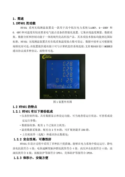
1、简述1.1NY401的功能NY401系列无线测温装置是一款用于高中低压电力系统(110KV,6—35KV和0.4KV)和对温度有较高要求电气接点设备的智能化装置。
它集在线温度测量、数据采集、数据分析和控制功能于一体的现代化高科技产品。
其各项技术指标均能到达国际标准,NY401无线测温装置具有在线采集温度接点数可设定,数据中续单元可根据现场情况而可选。
该装置提供通讯接口可与计算机监控系统连接,支持RS485接口MODBUS 通讯协议或多种协议,波特率可选。
图1装置外形图1.2 NY401的特点1.2.1 NY401有以下部份组成·仪表控制终端,具有数据显示和设定功能,可当地查看运行状态,可查看或设定运行参数;·数据接收器,配有1个已装在主机里;·温度数据采集器,配有由3至9路;可扩展到最多250路。
·上位机软件(选配)和通讯协议数据包;1.2.2 安全性高,可靠性好NY401在设计过程中采用了多种抗干扰措施,能够在电力系统中稳定运行。
静电放电抗扰符合4级;电快速瞬变脉冲群抗扰性符合4级,高压冲击抗扰符合4级;浪涌抗扰符合3级;面板防护等级符合IP54;壳体防护等级符合IP20。
1.2.3 体积小,安装方便NY401无线测温装置控制终端外形尺寸符合DIN96×96标准,壳体深度为78mm,采用自锁面板式安装机构,无需螺丝固定即可安装。
小巧的外形和简洁的安装方式使NY401的拆装非常方便;NY401温度数据采集器由捆绑式安装,无须打孔和使用安装工具,调试和安装非常方便。
1.2.4 系统接线方便灵活系统接线方式简单,人性化,不须有专业知识就可以安装。
1.2.5 显示直观、操作简便大尺寸专用液晶模块可以实时显示多项信息,配合明亮的背光,使操作者在光线差的情况下也能准确阅读数据。
操作方式人性化,操作者能在短时间内掌握,阅读数据和参数设置等操作将变得简单易行。
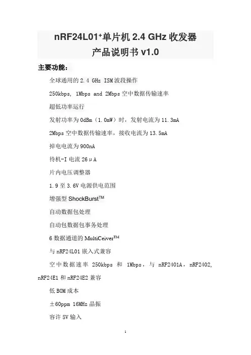
nRF24L01+单片机2.4 GHz收发器产品说明书v1.0主要功能:全球通用的2.4 GHz ISM波段操作250kbps, 1Mbps and 2Mbps空中数据传输速率超低功率运行发射功率为0dBm(1.0mW)时,发射电流为11.3mA2Mbps空中数据传输速率,接收电流为13.5mA掉电电流为900nA待机-I电流26μA片内电压调整器1.9至3.6V电源供电范围增强型ShockBurst TM自动数据包处理自动包数据包事务处理6数据通道的MultiCeiver TM与nRF24L01嵌入式兼容空中数据速率250kbps 和1Mbps,与nRF2401A,nRF2402, nRF24E1和nRF24E2兼容低BOM成本±60ppm 16MHz晶振容许5V输入紧凑的20引脚4x4mm QFN封装应用无线 PC外围设备鼠标,键盘和遥控器三和一桌面捆绑先进的媒体中心遥控器网络电话耳机游戏控制器蓝牙模块运动手表和传感器消费电子产品射频遥控器家庭和商业自动化超低功率无线传感器网络RFID 射频识别资产跟踪系统玩具免责条款北欧半导体ASA有权做出随时更改,提高产品可靠性、功能或设计,不另行通知。
北欧半导体ASA不承担由于应用程序或使用任何所述产品或电路引起的责任。
所有应用程序的信息咨询,不构成说明书的组成部分。
极限值超过一个或多个限制的应力可能会造成设备永久性损坏。
这些应力等级只有在这样或那样的操作环境中提出,在规范中没有给出。
长时间暴露在限制值附近可能会影响设备的可靠性。
生命支持应用这些产品并非为因故障会引起人身伤害的维生装备,设备或系统设计的。
北欧半导体ASA客户使用或出售这些产品,他们将自担风险并同意完全赔偿北欧半导体ASA因使用不当或销售行为造成任何损害。
详细联系方式访问www.nordicsemi.no进入北欧半导体销售办事处和全世界的分销商网站总办公室:Otto Nielsens vei 127004 Trondheim电话: +47 72 89 89 00传真: +47 72 89 89 89www.nordicsemi.no写作惯例本产品规范遵循一套排版规则,文档一致,容易阅读。

1. Intended useThe two versions of the mobile filter unit UFM 41 according ti the technical parameters of the data sheet 4006 are designed for the finefiltration of operating fluids with dirt particles 200 Micron. Larger particles may lead to premature wear of the gearpump.2. Commissioning The filter unit is supplied and delivered ready for operation: - The filter unit is not connected to the electric network. - The motor protection switch is shut off.-The suction and discharge hoses are wound up and the lances are in their respective locating tubes. - The unit is equiped with a filter elemet. - The draining and airbleeding screws and the filter lid are closed.-The filter housing holds roughly 5 l of operating fluid left over from the previous filter process. (It is recommended to mark a reference to the last filtered operating fluid on the filter unit). Before each commissioning the cleanliness of the lances, particulary that of the discharge hose, must be checked. Contaminated lances are to be cleanes with solvent before they are lowered into the fluid that is going to be filtered. The suction anddischargehoses are lowered into the respective tanks. During the operation of the filter unit the lance of the suction hose must be immersed in the fluid up to 50mm minimum. Make sure that the fluid that is to be filtered can easily enter and exit the lances of the hoses.Connect the filter unit the electric network (Note working voltage and kind of current!).The unit is turned on and off by means of the motor protection switch. After operating the unit or after maintenance and repair works the initial state has to be restored.3. Changing the element The filter element must be exchanged when the clogging indicator shows a pressure of 6 bar. For the exchanging of the element the filter unit has to be in initial state. The drain screw …E3“ and the airbleeding screws …E1“ are opened and the fluid left over in the filterunit is drained into the oil tray. The fluid gathered in the oil tray is to be treated as contaminated fluid. It is cleared from the oil tray by inclining the entire unit.When no more fluid emerges from the drain holes, the lid of the filter unit is opened and the filter element can be taken out, Dependingon the degree of contamination, the filter housing has to be cleaned before the new element can be inserted. The exchange element is taken out of ist wrapping just before it is inserted into the housing. The element must be checked on ist integrity (no visible mechanic damages) and ist completeness (O-ringes in the circular groove of the element). After insertion of the new filter element into the housing, the lid is put on and tightened by means of the locknut (torque: 60Nm). During the entire process of exchanging of the element particular attention has to be paid to preventing the contamination of either the filter element or the housing.Finally, the drain and aurbleeding screws are tightened.4. Cleaning the filter housingAfter the filtration of heavily contaminated fluid and when visible dirt particles are found in the filter housing, a thorough cleaning of thelatter becomes necessary. The housing is cleaned upon the exchange of the filter element. The drain screw …E3“ is opened. The inside of the housing is cleaned with conventional brushes and detergents.During the entire cleaning process make sure that no dirt particles get to the inside of the element (clean-oil side)(drill hole diameter 55of the locating peg) and that no solvent remains in the housing.5. Venting Generally, a separate airbleeding is not necessary. At a pressure of 6 bar the air blocked in the filter housing cannot dissolve into the fluid and is evacuated ba the discharge hose. In case a separate airbleeding connection is required ba the user, the filter unit is to be equired with a airbleeding unit according to data sheet no. 1650.Order reference of the airbleeding unit: - mini measurement connection MA.3.ST - high pressure hose M16.630 (length 630 mm) or- high pressure hose M16.2000 (length 2000 mm) - spray protection M166. General information - Every time the lid of the housing has been opened, the condition of the flat gasket 162x144x2 has to be checked. Damaged gaskets have to be replaced.- Torque of locknut: 60 Nm.- Filter units with mototr protection switch shut themselves off automatically after 5 min. of an operating pressure of 6 bar. EDV 10/95 - Englisch+49 (0)6205 2094-0 +49 (0)6205 2094-40 phone fax Friedensstrasse 41, 68804 Altlussheim, Germany e-mail url**************************/filtration。
目录1、概述 (2)2、工作原理 (2)3、整机结构名称 (2)4、电气原理 (3)5、产品特点.......................................................................................................3-46、使用条件 (4)7、安装操作指南 (5)8、维护保养 (5)9、配套清单 (5)9、变幅杆更换...................................................................................................6-7上海生析超声仪器有限公司1、概述上海生析超声仪器有限公司是一家集研究、设计、生产、销售以及维修超声波设备的专业产家。
生析公司有着集十多年生产超声波设备经验,设计及生产多种规格超声设备,产品种类有台式超声波清洗器、工业超声波清洗、超声波细胞破碎仪、超声波乳化仪、超声波处理器、超声波塑料焊接机、超声波换能器等等。
其产品广泛应用于全国高等院校的实验室、光学工业、珠宝首饰、航天工业、五金工业、汽车制造工业。
生析超声仪器有限公司以先进雄厚的技术力量,不断开发新产品,“高技术、高品质、优质的售后服务” 是生析公司的宗旨。
它将为广大客户提供全面的超声设备与服务。
2、工作原理超声换能器震动时产生的超声波作用于液体时,液体中每个气泡的破裂会产生能量极大地冲击波,相当于瞬间产生几百度的高温和高达上千个大气压,这种现象被称为“空化效应”。
超声空化是强超声在液体媒质中引起的一种特有的物理过程,它伴随有许多奇妙的现象和惊人的效应。
空化基本效应表现为高温效应,放电效应,发光效应,以及冲击、压力效应等等。
人们正是利用这些独特的效应而广泛应用于医药、生物、化学、物理等领域。
3、整机结构名称前面板后面板①连接线缆②套筒③换能器④变幅杆⑤液晶控制器⑥仪器机箱⑦输出插座(连接换能器)⑧仪器铭牌⑨保险丝座⑩总电源插座(11)总电源开关(12)输入插座(连接温度探头)(13)过流保护指示4、电气原理1.发生器本发生器的原理方框示意图:超声电路结构2.换能器所采用的压力换能器是夹心单螺钉结构,不同型号和功率的换能器配用不同规格和数量的电压陶瓷片。
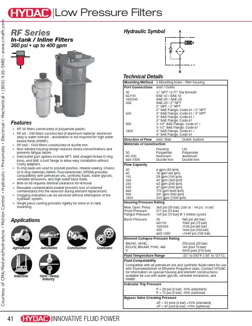
ApplicationsAgriculturalAutomotiveConstructionGearboxesIndustrialSteel / HeavyIndustryTechnical DetailsMounting Method 4 Mounting holes - filter housing Port Connections Inlet / Outlet30 60/110 160/240 330 660 950 1300½” NPT / 0.71” Dia Smooth SAE-12 / SAE-12SAE-20 / SAE-20SAE-20 / 2” NPT 2” NPT / 2” NPT2” SAE Flange, Code 61 / 2” NPT 3” SAE Flange, Code 61 / 3” NPT 3” SAE Flange, Code 61 / 3” SAE Flange, Code 613-1/2” SAE Flange, Code 61 / 3-1/2” SAE Flange, Code 614” SAE Flange, Code 61 / 4” SAE Flange, Code 61Direction of Flow Inlet: Side Outlet: bottom Materials of Construction3060-330 660-1300Housing Polyamide Aluminum Ductile IronLidPolyamide Aluminum Ductile IronFlow Capacity306011016024033066095013008 gpm (30 lpm)16 gpm (60 lpm)29 gpm (110 lpm)42 gpm (160 lpm)63 gpm (240 lpm)87 gpm (330 lpm)174 gpm (660 lpm)251 gpm (950 lpm)343 gpm (1300 lpm)Housing Pressure Rating Max. Oper. Press:Proof Pressure:Fatigue Pressure:360 psi (25 bar); (size 30 - 145 psi, 10 bar)217 psi (15 bar)145 psi (10 bar) @ 1 million cyclesBurst Pressure:3060/110160/240330660-1300580 psi (40 bar)1080 psi (75 bar)1230 psi (85 bar)1440 psi (100 bar)>1440 psi (100 bar)Element Collapse Pressure RatingBN/HC, W/HC,ECO/N, BN/AM, P/HC, AM V290 psid (20 bar)145 psid 10 bar) 3045 psid (210 bar)Fluid Temperature Range -22° to 250°F (-30° to 121°C)Fluid CompatabilityCompatible with all petroleum oils and synthetic fluids rated for use with Fluoroelastomer or Ethylene Propylene seals. Contact HYDAC for information on special housing and element constructions available for use with water glycols, oil/water emulsions, and HWBF.Indicator Trip PressureP = 29 psi (2 bar) -10% (standard)P = 72 psi (5 bar) -10% (optional)Bypass Valve Cracking PressureΔP = 43 psid (3 bar) +10% (standard)ΔP = 87 psid (6 bar) +10% (optional)FeaturesUÊRF 30 filters constructed of polyamide plastic.UÊ R F 60 - 330 filters constructed of aluminum material. Aluminum alloy is water tolerant - anodization is not required for high water based fluids (HWBF).UÊRF 660 - 1300 filters constructed of ductile iron.UÊ N on-welded housing design reduces stress concentrations and prevents fatigue failure.UÊ I nlet/outlet port options include NPT, SAE straight thread O-ring boss, and SAE 4-bolt flange to allow easy installation without costly adapters.UÊ O -ring seals are used to provide positive, reliable sealing. Choice of O-ring materials (Nitrile, Fluoroelastomer, EPDM) provides compatibility with petroleum oils, synthetic fluids, water-glycols, oil/water emulsions, and high water base fluids.UÊBolt-on lid requires minimal clearance for removal.UÊ R eusable contamination basket prevents loss of retained contaminants into the reservoir during element replacement.UÊ C logging indicators can be serviced without interruption of the hydraulic system.UÊ S ingle piece casting provides rigidity for inline or in-tank mounting.RF SeriesIn-tank / Inline FiltersÎÈäÊ«Ã ÊUÊÕ«ÊÌ Ê{ääÊ}« ÊC o u r t e s y o f C M A /F l o d y n e /H y d r a d y n e ŀ M o t i o n C o n t r o l ŀ H y d r a u l i c ŀ P n e u m a t i c ŀ E l e c t r i c a l ŀ M e c h a n i c a l ŀ (800) 426-5480 ŀ w w w .c m a f h .c o mModel CodeRF BN/HC 330 D L 10 H 1 . X / 16 - V - B6Filter TypeRF =Return Line FilterElement Media BN/HC = Betamicron ® (Low Collapse) ECO/N = ECOmicron ® (Low Collapse) AM = Aquamicron ® BN/AM = Betamicron ®/Aquamicron ®1 P/HC = Polyester W/HC = Wire Screen Size 30, 60, 110, 160, 240, 330, 660, 950, 1300Pressure Rating B = 145 psi (10 bar) (size 30 only) D = 360 psi (25 bar)Type of Connection B = 1/2” NPT (size 30) M = SAE 48 Flange (size 660)C = SAE 12 (sizes 60, 110) N = SAE 48 Flange Inlet / 3” NPT Outlet (size 660) E = SAE 20 (sizes 160 - 330) O = SAE 56 Flange (size 950) G = 2” NPT (size 330)P = SAE 64 Flange (size 1300)L = SAE 32 Flange Inlet / 2” NPT Outlet (size 330)Filtration Rating (micron) 3, 5, 10, 20 = BN/HC, ECO/N 10, 20 = P/HC 3, 10 = BN/AM25, 74, 149 = W/HC40 = AMType of Static or ΔP Clogging Indicator A, B/BM, C, D, HType Number 1 = Standard ConnectionModification Number (latest version always supplied) Inlet Port Configuration 3 = NPT (sizes 30 & 330) 12 = SAE Straight Thread Inlet/Outlet Connections (sizes 60, 110, 160, 240) 16 = SAE Flange Code 61 Inlet Connections (sizes 330 - 1300 only)Seals(omit) = Nitrile (NBR) (standard) V = Fluoroelastomer (FPM)EPR = Ethylene Propylene (EPDM)Bypass Valve (omit) = 43 psid (3 bar) (return line - standard) KB = No Bypass (flushing system) not available with ECO/NB6 = 87 psid (6 bar) (return line)B1 = 15 psid (1 bar) (lubrication or coolant applications) B0.2 =3 psid (0.20 bar) (suction line)SupplementarySO103H = Modification of BN4HC & W/HC Elements For Phosphate Ester Fluids L24, L48, L110, L220 = Lamp for D-type clogging indicator (LXX, XX = voltage) DE = ΔP Indicator (sizes 660, 950, 1300)Model Codes Containing RED are non-stock items — Minimum quantities may apply – Contact HYDAC for information and availabilityReplacement Element Model Code0330 R 010 BN4HC / VSize0030, 0060, 0110, 0160, 0240, 0330, 0660, 0950, 1300Filtration Rating (micron) 3, 5, 10, 20 = BN4HC, ECO/N 10, 20 = P/HC 3, 10 = BN/AM25, 74, 149 = W/HC 40 = AM Element MediaBN4HC, ECO/N, P/HC, BN/AM, W/HC, AM Supplementary Details (omit) = standard V = Fluoroelastomer (FPM) sealsClogging Indicator Model CodeVR 2 B . X / Indicator PrefixVR = Return Filters Trip Pressure 2 = 29 psid (2 bar) (return filters) 5 = 72 psid (5 bar) (optional)Type of Indicator A = no indicator, plugged port B/BM = Visual pop-up (auto/manual reset) C = Electric switch D = Electric switch and light H = Electric pressure switch Modification Number Supplementary Details Light Voltage (D type indicators only) L24 = 24V L110 = 110V Seals(omit) = Nitrile (NBR) (standard) V = Fluoroelastomer (FPM)(For additional details and options, see Clogging Indicators section.)NPT available w/Adapter C o u r t e s y o f C M A /F l o d y n e /H y d r a d y n e ŀ M o t i o n C o n t r o l ŀ H y d r a u l i c ŀ P n e u m a t i c ŀ E l e c t r i c a l ŀ M e c h a n i c a l ŀ (800) 426-5480 ŀ w w w .c m a f h .c o mDimensions shown are for general information and overall envelope size only. Weights listed are without element. For complete dimensions please contact HYDAC to request a certified print.RF 603.54”RF 1106.30”RF 1605.12”3.77”(96mm ) 4.96”(126mm )RF 2407.48”)))Clearance required)12.6”mm )OUTLETOUTLETOUTLETOUTLETOUTLETG 1/2RF95013.78”mm )RF130018.11”mm )))Clearance required Clearance required for element removal)Dimensions RF 30RF 60 - 240RF 330Mounting PatternRF 660RF 950 - 1300C o u r t e s y o f C M A /F l o d y n e /H y d r a d y n e ŀ M o t i o n C o n t r o l ŀ H y d r a u l i c ŀ P n e u m a t i c ŀ E l e c t r i c a l ŀ M e c h a n i c a l ŀ (800) 426-5480 ŀ w w w .c m a f h .c o mRF 30 HOUSINGQ in gpmQ in l/min052520151001.61.20.80.412345678051015202530Sizing InformationTotal pressure loss through the filter is as follows:Assembly P = Housing P + Element P Housing Curve:Pressure loss through housing is as follows:Housing P = Housing Curve P xActual Specific Gravity0.86Adjustments must be made for viscosity & specific gravity of the fluid to be used! (see sizing section on page 19)Element K FactorsΔP Elements = Elements (K) Flow Factor x Flow Rate (gpm) x Actual Viscosity (SUS) x Actual Specific Gravity(From Tables Below)141 SUS 0.86All Element K Factors in psi / gpm.C o u r t e s y o f C M A /F l o d y n e /H y d r a d y n e ŀ M o t i o n C o n t r o l ŀ H y d r a u l i c ŀ P n e u m a t i c ŀ E l e c t r i c a l ŀ M e c h a n i c a l ŀ (800) 426-5480 ŀ w w w .c m a f h .c o m。
fsn41n参数设置说明书参数设置说明书:FSN41N1.介绍FSN41N是一款高性能的网络参数设置工具,用于配置网络设备的各种参数。
通过使用FSN41N,用户可以轻松地管理和设置网络设备的各项参数,提高网络设备的运行效率和性能。
2.安装在安装FSN41N之前,请确保系统满足以下要求:- 操作系统:Windows 7及以上版本-硬件要求:4GBRAM,100GB可用存储空间按照下列步骤安装FSN41N:2)双击安装程序,按照提示进行安装3)安装完成后,启动FSN41N,开始设置参数。
3.主要功能FSN41N具有以下主要功能:-设置网络连接:用户可以设置设备的IP地址、子网掩码、网关等基本网络连接参数。
-配置无线网络:用户可以设置无线网络的名称、加密方式、密码等参数。
-管理设备访问:用户可以设置设备的访问权限,包括用户名称、密码、权限级别等。
-配置路由器:用户可以设置路由器的路由表、NAT、端口映射等参数。
4.使用指南在使用FSN41N进行参数设置之前,请确保已连接到网络设备。
按照以下步骤进行参数设置:1)运行FSN41N应用程序。
2)在菜单栏中选择所需的参数设置选项,如网络连接、无线网络等。
3)输入相关参数,如IP地址、密码等。
4)点击保存按钮,保存设置。
5)完成参数设置后,重新启动设备以使设置生效。
5.注意事项在使用FSN41N进行参数设置时,请注意以下事项:-仔细检查输入的参数是否正确,特别是IP地址、子网掩码等网络连接参数。
-在设置路由器等涉及网络连接的参数时,确保了解设备的工作原理和网络拓扑。
-避免在网络繁忙时进行参数设置,以免影响网络设备的正常工作。
-在参数设置完成后,确保重新启动设备以使设置生效。
6.常见问题解答-Q:我在参数设置过程中遇到错误提示,该怎么办?A:首先,检查输入的参数是否正确。
如果错误提示仍然存在,请尝试重新启动设备和应用程序,并重新进行参数设置。
-Q:我忘记了设备的登录密码,该怎么办?A:在设备上通常有一个恢复出厂设置按钮,按下该按钮可以将设备恢复为出厂默认设置,包括登录密码。
壁挂数码管王字壳温湿度变送器说明书(WIFI型)Ver2.0目录第1章产品简介 (3)1.1产品概述 (3)1.2功能特点 (3)1.3主要技术指标 (3)1.4产品选型 (4)1.5设备信息 (4)第2章设备安装及使用 (7)2.1设备安装说明 (7)2.2设备使用 (7)第3章监控平台介绍 (11)第4章常见问题及解决办法 (11)第5章注意事项 (11)第6章免责声明 (12)附录:部分探头尺寸 (13)第1章产品简介1.1产品概述该产品为壁挂高防护等级外壳,防护等级IP65,防雨雪且透气性好。
电路采用美国进口工业级微处理器芯片、进口高精度温度传感器,确保产品优异的可靠性、高精度和互换性。
可采集数据并通过WIFI方式上传到服务器。
本产品充分利用已架设好的WIFI通讯网络实现数据采集和传输,达到数据集中监控的目的。
可大大减少施工量,提高施工效率和维护成本。
设备7-30V宽压供电,外壳防护等级高,能适应现场各种恶劣条件。
1.2功能特点■采用瑞士进口的测量单元,测量精准■通过WIFI方式上传数据,支持局域网内通信、跨网关广域网通信■支持动态域名解析DNS■数据采集频率2s/次,数据上传频率1s~65535s/次可设■可接免费的云平台■产品采用壁挂式防水壳,安装方便,防护等级高。
1.3主要技术指标直流供电(默认)DC7-30V最大功耗0.1W(DC24V)A准精度湿度±2%RH(60%RH,25℃)温度±0.4℃(25℃)B准精度(默认)湿度±3%RH(60%RH,25℃)温度±0.5℃(25℃)变送器电路工作温湿度-40℃~+60℃,0%RH~95%RH(非结露)探头工作温度-40℃~+120℃默认:-40℃~+80℃探头工作湿度0%RH-100%RH温度显示分辨率0.1℃湿度显示分辨率0.1%RH温湿度刷新时间1s长期稳定性湿度≤1%RH/y温度≤0.1℃/y响应时间湿度≤8s(1m/s风速)温度≤25s(1m/s 风速)数据上传时间默认10s/次,1s~65535s 可设数据采集时间2s/次WIFI 通信参数802.11b/g/n安全性安全方式WEP/WPA-PSK/WPA2-PSK 加密类型WEP/TKIP/AES1.4产品选型1.5设备信息尺寸:PR-公司代号300SMG-壁挂数码管王字壳WS-温湿度变送、传感器WIFI-WIFI 型1外置铜头3外置西门子头4外置精装探头5外延精装探头6外延防水探头7外延高灵敏度探头9外延金属防水探头A 外延四分管螺纹探头B 外延宽温探头ZJ 外延夹持探头HD 活动螺纹探头FW蜂窝型探头(相比外延金属防水探头对湿度环境反应灵敏,不防尘,无法使用在粉尘较大的环境,抗2.5m/s 风)FF不锈钢防风探头(316L 不锈钢材质,耐腐蚀性强,高温强度优秀,间隙小,可抗30m/s 风,可阻挡细小粉尘穿透)数码管王字壳温湿度传感器外观图:1345679AB ZJ HD FWFF序名称内容号①设备贴膜上面带有产品logo以及名称②电源线DC5.5*2.1规格;使用配件电源适配器插入供电③传感器温湿度传感器④安装孔位使用配件膨胀螺丝包,将设备安装至墙面等需要安装的位置包装内容主设备×1产品合格证、保修卡×1膨胀螺丝包(含2个自攻螺丝及2个膨胀塞)×112V电源适配器×1第2章设备安装及使用2.1设备安装说明设备主体的安装2.2设备使用接通电源将电源适配器连接至设备的供电接口,再接通电源连接至网络1下载配置工具,使用QQ扫描二维码(仅限安卓手机),点击“客户端本地下载”,下载完成后根据手机提示将APP安装。

深圳市拓力智慧科技有限公司地址:深圳市福田区上梅林广厦路7号菉华科技大楼三楼1德国安诺尼SPECTRAN HF V4系列频谱分析仪产品操作手册请您在使用测量设备之前,仔细阅读下面的手册,本手册将为您正确操作设备提供重要的帮助信息。
重要提示:如果您不是直接向我们采购的话,请您一定将随箱的注册登记卡寄给我们!首先,恭喜您!您所购买的SPECTRAN系列高频频谱分析仪是一款测量高频电磁场的专业设备。
请注意,如果您需要测量低频电磁场(高压线,铁路牵引供电,家用电器等),您需要另外购买我们的SPECTRAN NF系列低频频谱分析仪。
因此如果您的测量领域比较广,我们建议您购买我们价格优惠的测量仪器套装组件,您可以在任何时候来购买添加套装组件,只需支付相应的差价即可。
而且如果您需要,我们的设备在任何时候均可以升级到更高级SPECTRAN型号。
所有的选购件(例如内存扩展、长效电池)可以随时根据型号来升级。
另外请使用我们免费提供的PC频谱分析软件“MCS”。
它提供更多的功能,包括大量用于评估各类信号的优化设置,包括信道和运营商相关信息,PEP峰包功率测量和创新的SIS 扫描。
如果更换设备,不论是升级还是交换,我们的设备最好是回收,关于此类问题请参考我们的保修服务条款,在“Aaronia保修”章节中可以查看相关内容。
我们提供最专业化的服务及产品,欢迎您登录我们的主页,选择适合您的产品。
客户至上!深圳市拓力智慧科技有限公司地址:深圳市福田区上梅林广厦路7号菉华科技大楼三楼2目录1.0 安全须知 (4)2.0 产品标配 (5)3.0 频谱仪显示屏 (6)4.0 按键布置 (7)5.0 首次测量/模式 (9)5.1 Spectrum analysis频谱分析操作模式 (10)5.2 HOLD功能 (11)5.3 “平移逼近”功能 (12)5.4 暴露限值计算模式(Exposure limit calculation) (12)5.5 音频输出操作模式audio output(解调): (14)5.6 宽带检波器操作模式broadband detector(峰值功率计) (16)6.0 设置自定义的频率范围 (18)7.0 主菜单 (20)7.1 中心(中心频率) (21)7.2 Span (Frequency range width)/跨度(频宽) (21)7.3 fLow & fHigh (开始和停止频率) (22)7.4 RBW (分析带宽) (22)7.5 VBW(视频滤波器) (22)7.6 SP Time(采样时间) (23)7.7 Reflev(参考电平) (23)7.8 Range(动态范围) (23)7.9衰减器 (24)7.10放大器(内部前置放大器) (24)7.11解调器/音频分析/ GSM解码器 (24)7.12音频指示器(音频指示器/ “窃听跟踪器”) (25)7.13检波器(检波类型) (25)7.14 Disp(显示模式) (26)7.15 单位(单位设置) (27)7.16 MrkCnt(设置标记数量) (27)7.17 MrkLvl(设置标记的开始电平) (27)7.18 MrkDis(标记显示模式) (27)7.19 BackBB(改变柱形图显示模式) (28)7.20 AntTyp(配置连接天线) (28)7.21Cable(配置天线连接馈线/衰减器) (28)7.22 RefOff(设置偏移量或者UBBV前置放大器) (28)7.23 GSMbst (选择GSM Burst-Type) (29)7.24 GSMdst(选择GSM Slot-Distance) (29)7.25亮度(设置显示亮度) (29)7.26 记录器(开始记录/日志数据) (29)7.27 RunPrg(执行程序) (30)7.28 Setup(组织程序) (30)深圳市拓力智慧科技有限公司地址:深圳市福田区上梅林广厦路7号菉华科技大楼三楼38.0正确的测量 (32)8.1底噪声 (32)8.2谐波 (33)8.3无线局域网和手机测量 (33)8.4 “自动”衰减模式 (33)8.5 灵敏度 (33)8.6测量误差 (34)8.7光标和缩放功能 (34)9.0提示和技巧 (36)10.0 暴露限值 (38)10.1 暴露限值(人身安全) (38)10.2.设备限值 (39)10.3 Limits for ecologically compatible construction (39)11.0 天线架设和操作 (41)12.0 连接 (41)12.1 External DC input (battery charger / mains operation)外部直流输入(电池充电器/主要操作方式) (41)12.2 Audio output(音频输出) (41)12.3 Jog Dial / volume control(滚动旋钮/音量控制) (41)12.4 USB connector(USB连接) (42)13.0 硬件设置 (42)14.0 频谱分析基础(略,见英文说明书) (44)15.0 物理单位(略,见英文说明书) (44)16.0 一些射频数学(略,见英文说明书) (44)17.0 换算表(略,见英文说明书) (44)18.0 频率表(略,见英文说明书) (44)19.0 注册登记卡和保修条款 (45)20.0 测量建议 (46)20.1 测试卫星电视信号 (46)20.2 测量电力线,ISDN,DSL,VDSL等 (46)20.3 直接连线测量 (47)20.4 监听电台 (47)20.5 底噪校准 (47)21.0 开发者平台,用户论坛和其他 (48)深圳市拓力智慧科技有限公司地址:深圳市福田区上梅林广厦路7号菉华科技大楼三楼41.0 安全须知注意:安装天线和适配器请勿过度用力,请使用我们随箱提供的SMA工具松动或锁紧SMA 连接器,它提供过大力矩的保护。
● 支持Dshot150、Dshot300和Dshot600。
Dshot为数字信号,抗干扰能力强,而且电调不需要校准油门行程。
● 信号线为双绞硅胶线, 增加其使用寿命同时更有效降低信号在铜线内传输所产生的干扰,使飞行更稳定。
1. 启动功率 (Startup power):启动功率可以设置从0.031到1.5的一个值。
它是启动过程中允许的最大功率,实际应用的功率取决于油门的输入值。
启动功率也会影响双向操作,因为启动功率也是用来限制在反向时一个施加的功率。
对于低转速电机,最大功率是有限的,为了便于低反电动势的电压检测,允许的最大功率可以通过启动功率这个参数来设置。
(Commutation timing):2. 进角进角可设置为 低/中低/中/中高/高,分别对应0°/7.5°/15°/22.5°/30°进角。
通常设置中进角即适用于大部分电机,但如果电机运转不顺畅时,可以尝试改变进角。
对于一些高感电机,其换向退磁时间较长,尤其在低速运转的时候,电机会在油门快速增加的情况下停转或者不顺畅。
将进角改高点会有有助于改善这个现象,因为高进角允许更长的换向退磁时间。
(Demag compensation):3. Demag补偿Demag补偿是防止电机由于换向引起停转的一个功能,典型的现象是在快速增加油门时电机停转或不顺畅,尤其在低转速运行时。
如前面所述,设置高进角可以帮助改善,但有可能降低效率。
一般情况下,Demag补偿参数的值越高,保护越好。
如果补偿值设置得太高,最大功率将有所降低。
转向 (Rotation direction):4.电机转向可以设置为正转/反转/双向。
在双向模式下,油门中点为零点,中点以上为正转,中点以下为反转;当选择双向操作时,油门编程被禁用。
(Beep strength):5. 鸣叫声强度设置正常运行下鸣叫声强度。
(Beacon strength):6. 警报音强度设置警报音响起时的强度。
We recognize that it’s not one approach for all—each industry, busi-ness and success measure is unique. Optimally engineered, Flukecameras are aligned to drive efficiency through the latest in ther-mography technology advancements. They offer everything needed for industrial professionals to safely, quickly and easily find, assess and solve mission-critical problems before they result in downtime, become costly or even disastrous.• In-focus images in a matter of seconds. LaserSharp™ Auto Focus uses a built-in laser distance meter that calculates and displays the distance from your designated target and immediately adjusts the focus.• Shoot images near…and far. Interchangeable Smart Lensesrequire no calibration and give you the versatility and image qual-ity needed to conduct inspections in almost any environment.•Simply the best optics to transmit energy and produce high quality infrared images. Fluke uses only 100 % diamond-turned germanium lenses with specialty coatings.• See more details when you adjust the level of infrared and visible light with patented IR-Fusion™ technology.• Edit and analyze images on camera—edit emissivity, enable color alarms and markers, and adjust IR-Fusion™ visual and infrared image blending.• Manage data, capture multiple measurements (mechanical,electrical and thermal) and organize them by piece of equipment with Fluke Connect™ software.• Inspect multiple complex targets or targets from varying distances. Capture a clear, accurate image focused throughout the field of view with MultiSharp™ Focus . The camera automatically pro-cesses a stack of images focused near and far with the Ti480 PRO and TiX580.BFluke Connect TMcompatibleTECHNICAL DATASUPERIOR IMAGE QUALITYRESOLUTION640 x 480 (307,200 pixels)SPATIAL RESOLUTION 0.93 mRad FIELD OF VIEW 34 °H x 24 °VTi401 PRO, Ti480 PRO, TiX501 and TiX580 Infrared CamerasPowerful, easy-to-use Fluke Connect™A comprehensive and connected software platform that represents the future ofintegrated equipment maintenance, monitoring, analysis and reporting. It’s easierthan ever to optimize thermal images, perform analytics, generate quick, customiz-able, robust reports, and export images to the format of your choice in the cloud. Andyou will be able to integrate with Fluke Connect—the largest integrated system ofmaintenance software and tools in the world.•Modern visual design•Intuitive navigation—easier to learn, easier and faster to work in•Simplified work flows•Simplified reporting workflow and better report templates•Fluke Connect Cloud storageDownload at Fluke Connect and Fluke Connect cloud storage not available in all countries.100% Focused–Every object. Near and far. MultiSharp™ Focus.Manual focus MultiSharp FocusPlease Note: Fluke Connect analysis and reporting software is available in all countries but Fluke Connect is not. Please check availability with your authorized Fluke distributor **Indicates Fluke Connect™ features that will be available soon. Watch the Fluke website for software and firmware updates.Ordering informationFLK-Ti401 PRO 60 Hz Infrared Camera FLK-Ti401 PRO 9 Hz Infrared Camera FLK-Ti480 PRO 60 Hz Infrared Camera FLK-Ti480 PRO 9 Hz Infrared Camera FLK-TiX501 60 Hz Infrared Camera FLK-TiX501 9 Hz Infrared Camera FLK-TiX580 60 Hz Infrared Camera FLK-TiX580 9 Hz Infrared CameraIncludedIncluded Infrared camera with standard infrared lens; AC power supply and battery pack charger (including universal AC adapters); two rugged lithium ion smart battery packs; USB cable; HDMI video cable; 4GB micro SD card; and adjustable hand strap. Available by free download: Fluke Connect™ desktop software and user manualTi401 PRO onlyRugged, hard carrying case, soft transport bagTi480 PRO, TiX501, TiX580 only Rugged, IP67 rated, airtight hard carrying case TiX501, TiX580 onlyAdjustable neck strapOptional accessoriesFLK-LENS/TELE2 Infrared Telephoto Lens (2X magnification)FLK-LENS/4XTELE2 Infrared Telephoto Lens (4X magnification)FLK-LENS/WIDE2 Infrared Wide Angle LensFLK-LENS/25MAC2 25 Micron Macro Infrared Lens TI-CAR-CHARGER Car Charger FLK-TI-VISOR3 Sun VisorBOOK-ITP Introduction to Thermography Principles Book TI-TRIPOD3 Tripod Mounting Accessory FLK-TI-BLUETOOTH Bluetooth headset FLK-TI-SBP3 Additional Smart BatteryFLK-TI-SBC3B Additional Smart Battery Charger FLK-TIX5XX-SBP4 Additional Smart BatteryFLK-TI-SBC3B Additional Smart Battery Charger TiX501 and TiX580 additional accessories FLK-TIX5X-LENS CAP Infrared Lens Cover FLK-TIX5XX-NECK Neck strap FLUKE-TIX5XX HAND Hand strapFLK-TI-BLUETOOTH Bluetooth Headset FLK-TIX5XX-HDMI HDMI CableVisit to get complete details on these products or ask your local Fluke sales representative.Fluke CorporationPO Box 9090, Everett, WA 98206 U.S.A.Fluke Europe B.V.PO Box 1186, 5602 BD Eindhoven, The NetherlandsFluke. Keeping your world up and running.®For more information call:In the U.S.A. (800) 443-5853 or Fax (425) 446-5116In Europe/M-East/Africa +31 (0)40 267 5100 or Fax +31 (0)40 267 5222In Canada (800)-36-FLUKE or Fax (905) 890-6866From other countries +1 (425) 446-5500 or Fax +1 (425) 446-5116Web access: ©2019 Fluke Corporation.Specifications subject to change without notice. 3/2019 6012099a-enModification of this document is not permitted without written permission from Fluke Corporation.All trademarks are the property of their respective owners. WiFi or cellular service required to share data. Smartphone, wireless service and data plan not included with purchase. First 5GB of storage is free. Phone support details can be viewed at /phones .Smart phone wireless service and data plan not included with purchase. Fluke Connect is not available in all countries.Preventive maintenance simplified. Rework eliminated.。
关键词:HAME设备预防保养
特殊特性:无
1.目的:
确保HAME电镀设备的状态与性能的完好,延长设备的有效使用寿命,减少设备的备件损耗,提高设备的稳定性。
2.适用范围:
本标准适用于HAME电镀设备的定期点检、周期性预防保养
3.周期;
设备保养周期为12个月
4.职责:
设备的预防保养、定期点检由本工序设备担当人员实施,产品品质由本工序工艺人员确认
5.注意事项:
5.1实施人员必须按照文件来点检和保养设备,并如实填写“点检成绩书”。
PM完成后由工艺人员确认产品质
量。
5.2特别要注意再有可能有制品通过的位置进行保养、点检时,要注意备件的紧固、位置偏移的控制等细节问
题,不能留有潜在的危险和隐患。
5.3对于所有药液单元管路、药液槽及泵必须检查是否有漏液的情况
5.4保养后的设备必须交设备主管确认
表(1)
表
(2)制造厂家: 6个月保养点检成绩书
计划点检日期:
判定是•否
是•否是•否是•否是•否是•否是•否是•否
是•否是•否
是•否是•否是•否是•否是•否是•否是•否是•否是•否是•否是•否
判定是•否
是•否是•否是•否是•否是•否是•否是•否
是•否是•否
是•否是•否是•否是•否是•否是•否是•否是•否是•否是•否是•否。
FS—N41p说明书
1、光纤放大器的调试方法和过程:
(1)SET键,此按钮可用于敏感度设定。
本传感器的基本原理为:通过光纤探头对不同介质折射率的感应,从而获得数字信号,显示在屏幕上,通过显示数值的大小与设定灵敏值的比较发送开关量。
(2)指示灯,此灯在传感器有信号输出时发生亮灭变化。
(3)“设定灵敏值”,在屏幕上显示为绿色,表明当前设定的灵敏值。
当探头采集到的数值变化至此数值时,传感器产生信号。
(4)“当前灵敏值”,在屏幕上显示为红色,显示传感器当前采集的数值。
(5)“选择按钮”,及左右箭头,可以实现各种功能的选择,相当于翻页键。
(6)“模式选择按钮”,此按钮可用于设定不同的工作模式。
2、接线方法。
3、灵敏度校准。
(1)全自动校准:在工件进入探头的灵敏区域时,按住“SET”键不放,保持3秒,灵敏值将会被设定,显示为绿色(2)两点校准:在工件未进入灵敏区域时,按住“SET”键保持三秒,有一个敏感值被记忆,然后将工件放置在敏感区域,按下“SET”键保持三秒,另一个敏感值被记忆,当敏感值从一个值变化为另一值时,传感器产生电平变化。
(3)一般校准:也可以通过按“选择按钮”,及左右键来增减敏感度的设定值。
(4)位置校准:在工件未进入灵敏区域时,按住“SET”键保持三秒,然后将工件放置在离探头一定距离,按下“SET”键保持三秒,一个敏感值被记忆,当工件每次到达此位置时,传感器产生电平变化。
4、常开常闭设定。
按下最右侧的开关选择按钮,可以选择,内部开关为常闭还是常开。