TCD720-820M发卡器说明书 V2.00
- 格式:doc
- 大小:258.00 KB
- 文档页数:10

多功能发卡器的使用方法一、2009-06-05 07:17一、主要功能:〈一〉接上电源,不与电脑连接,直接能达到功能1、外置5V电源(附送)。
2、能辨别MF1卡还是ID卡。
3、能辨别MF1卡是MF1 S50射频卡(包括兼容卡)还是MF1 S70卡。
4、能初步辨别MF1 S50卡是原装芯片还是兼容芯片。
5、能检查ID与MF1卡读写距离。
〈二〉接上电源,与电脑连接,能够达到功能1、附送测卡软件及发卡软件。
2、有8个COM口,兼顾到笔记本电脑多接口问题。
3、能检查ID卡ABA码(4H格式、6H格式、8H格式、10H格式可选)与维根码(WG26、WG34、WG42可选),并且能够单选ABA码或维根码,能够检测单张卡片也能连续检测多张卡片,同时可以转换成TXT文档,以供打码。
4、能检查MF1 卡(此处及以下所说MF1卡指“MF1 PHILIPS S50卡及兼容卡”,不包括MF1 S70卡)曼彻斯特码与ABA码(正读、反读可选),并且能够单选曼彻斯特码或ABA码,能够检测单张卡片也能连续检测多张卡片,同时可以转换成TXT文档,以供打码。
5、能检查MF1卡是否加密,能够检测单张卡片也能连续检测多张卡片,以判断该卡能否回收再次使用。
6、测卡软件能对MF1卡进行密码A加密处理,能够检测单张卡片也能连续检测多张卡片。
7、发卡软件能进行MF1卡各扇区数据读写、加减、密钥修改等功能操作。
8、发卡软件专门配备控制字各种选择及反推算功能。
二、适用客户:1、卡厂:各种序列号读写及MF1卡回收必备工具。
2、中间商:一台机具判断射频卡大概情况,并能初步判断卡厂供应MF1卡是否原装芯片。
3、系统商:初步判断供应商提供MF1卡是否原装芯片,并能进行数据读写等,同时可以根据控制字各种演测计算出最佳控制字方法4、直接客户:能判断IC卡是ID卡还是MF1卡,以及初步判断MF1卡所用芯片是否原装。
5、其它客户:通过这台机具,不懂射频卡或读卡机具客户,也能够对射频卡及读写机具初步入门。

720Stereo LooperCongratulations on your purchase of the 720 looper! Enjoy 720 total seconds of high-quality, stereo recording time and the ability to store 10 different loops. The 720 looper is packed with features such as reverse and ½ speed effects, playback fadeout, real-time progress display, and a convenient programmable second footswitch.WARNING: Your 720 comes equipped with an Electro-Harmonix 9.6DC-200 power supply (same as used by Boss® & Ibanez®: 9.6 Volts DC 200mA). The 720 requires 75mA at 9VDC with a center negative plug. Using the wrong adapter or a plug with the wrong polarity may damage your 720 and void the warranty.–FEATURES –-12 minutes of loop recording time-10 selectable, independent Loops that remain in memory until you erase them -High quality uncompressed audio: 24-bit A/D/A, 44.1kHz Sample Rate-Undo-Redo function (also available via optional footswitch)-Reverse and ½ speed effects at the touch of a button or a footswitch tap-Footswitch selectable for Stop or Effects-Handy playback progress mode with seek function-Unlimited overdubbing-Optional external footswitch control for selecting loops and Undo/Redo-Adjustable fadeout (trails) time-Programmable looping order: REC/PLAY/DUB or REC/DUB/PLAY-AC adaptor included or may be battery powered–CONTROLS and INDICATORS –LEVEL Knob –Controls the output level of the Loop being played. Your dry signal remains at unity signal level from input to output. The dry signal also remains analog throughout the 720.LOOP Footswitch– Use the LOOP footswitch to record, overdub, and playback loops. The LOOP footswitch can also be used to stop and undo-redo loops. See the QUICK START GUIDE on page 5 to learn how to use this footswitch to create loops.STOP/FX Footswitch–The STOP/FX footswitch can be set to either STOP mode or FX mode. Select either mode by pressing and holding the PUSH: MODE button for 2-seconds. When in STOP mode, a DOT appears on the display next to the STOP label. When in FX mode, the DOT is off.REC LED – Indicates when a loop is being recorded or overdubbed.PLAY LED – Indicates when a loop is being played or overdubbed.MEM LED – Indicates loop audio is in memory for the current loop bank.LOOP Knob and PUSH: MODE Button– The LOOP knob has no pointer because it is attached to a rotary encoder that can be continuously rotated in either direction. This knob also has a PUSH: MODE button with two functions: 1) to cycle through one of three available modes, and 2) once a mode is selected, to adjust the value of that mode from 0-9. All modes and values are shown on the digit display.SELECTING/ ADJUSTING MODES – The 3 selectable modes are toggled on and off by pressing the MODE button once. When mode-select is active, the digit display will flash the currently selected mode. Turn the LOOP knob to cycle through the three possible modes:L = Loop Selectp = Loop ProgressF = Fadeout TimeWhen you arrive at the mode you would like to adjust, press the MODE button once to select the mode. The display will stop flashing and it will show the selected mode value from 0-9. The selected mode can now be adjusted with the LOOP knob from 0-9.REVERSE Button – Press the REVERSE button to play the loop in reverse. The REVERSE button glows red when enabled. Reverse can be used at any time to playback or overdub a loop.½ SPEED Button– Pressing the ½ SPEED button causes the pitch of the loop to go down one octave and the tempo is halved. If a loop is overdubbed during half-speed mode, returning to normal speed playback causes the pitch of the overdub to go up one octave and the tempo is doubled. The ½ SPEED button glows red when enabled. ½ SPEED can be used at any time during playback or while overdubbing a loop.FX LED – Indicates when an effect is active. The FX LED automatically lights when the REVERSE or ½ SPEED buttons are used and the STOP/FX footswitch is programmed to operate in STOP mode. Alternatively, the FX LED will toggleon/off each time the STOP/FX footswitch is pressed and programmed to operate in FX mode.MONO/L INPUT–¼” Left Instrument/Line Input Jack. Plug the output of your instrument or another effects pedal into this jack. If you use just one input we recommend you use the MONO/L input. The input impedance presented at this jack is 1MΩ. The maximum allowabl e signal level into this jack is +6 dBu. The input is unbalanced.R INPUT –¼” Right Input Jack. Plug the output of your instrument or another effects pedal into this jack. Use this jack for stereo recording. The input impedance presented at this jack is 1MΩ. The maximum allowable signal lev el into this jack is +6 dBu; it is an unbalanced input.MONO/L OUTPUT–¼” Left Output Jack. The Left output signal is sent through this jack. The dry signal present at the Left input will be output on the MONO/L Output jack. The source impedance of the MONO/L Output is approximately 330Ω.Note: the MONO/L OUTPUT jack also functions as a power switch when powered from a battery. Disconnect the cable to save battery power when the 720 is not in use.R Output –¼” Right Ou tput Jack. The Right output signal is sent through this jack. The dry signal present at the Right input jack is output to the R Output jack. The source impedance of the R Output is 330Ω.FC Jack–¼” TRS Foot Controller Jack. Use this jack with popular three button foot controller units to control the 720 bank up, bank down, and instant undo-redo.The Digitech® FS3X 3-Button Footswitch [see: /en-US/products/fs3x-3-button-footswitch] is recommended for this application. If using this product, the following switch labels on the FS3X control the following 720 functions: DOWN advances the 720 bank down; UP advances the 720 bank up; and, MODE will instantly undo or redo.The circuit required for the foot controller is as follows:TIP / S1 = Instant Undo-RedoRING / S2 = Bank DownDiode-AND TIP+RING / S3 = Bank Up9V Power Jack – Plug the output of the supplied AC adapter into the 9V power jack located at the top of the 720. The Stereo Looper 720 draws 60mAtyp./75mA max. at 9VDC with a center-negative plug. The Stereo Looper 720 accepts Boss® and Ibanez® style AC adapters.–QUICK START GUIDE –RECORDING A LOOP1.To record a Loop: simply select an empty bank and press the LOOPfootswitch once. The REC LED will light solid and recording begins immediately.2.To stop recording the loop, press the LOOP footswitch again once. The RECLED will turn off, the PLAY LED will turn on, and the loop will begin playing immediately. The MEM LED will also light solid, indicating the presence of recorded loop memory.Note: if the recording order is REC/DUB/PLAY, the REC LED remains on when the LOOP footswitch is pressed again once. Recording will stop and the 720 will continue immediately into overdub mode.3.All Loops play indefinitely. Each time the loop repeats, the PLAY LED willturn off briefly.4.After a loop is recorded, the length is subtracted from the total looprecording time of 720 seconds.STOPPING & STARTING LOOP PLAYBACK1.To stop loop playback, press the LOOP footswitch two times quickly.Alternatively, press the STOP footswitch once to immediately stop playback.2.Note: if using the LOOP footswitch to stop, the REC LED will turn ontogether with the PLAY LED during the first press. Both LEDs turn offduring the second press and playback stops immediately.3.While stopped, press and release the Footswitch once to start playback.The PLAY LED will light to indicate that the loop is playing. RECORDING AN OVERDUB1.To record an overdub, make sure a Loop is playing back. If a loop is notplaying, press the LOOP footswitch once to begin playback. The PLAY LED will turn on and the loop will begin playing immediately.2.To start recording an overdub, press the LOOP footswitch once. The RECLED will turn on—together with the PLAY LED—and audio will be recorded on top of the original loop. No volume loss will occur to the previously recorded portion of the loop.3.To stop overdubbing the loop: press the LOOP footswitch again once. TheREC LED will turn off, and the loop will continue playing along with the overdubbed audio.4.Overdubbing will never change the length of the loop.5.The 720 can overdub indefinitely, allowing you to continuously overdub newaudio onto your loop.6.After finishing one or more overdubs, the UNDO-REDO function is enabled.You may undo, then redo the last overdub as many times as you like.–REFERENCE GUIDE –STOP FOOTSWITCH1.To use the second footswitch to stop loop playback, press and hold theMODE button for two seconds. A dot will appear on the digit display next to the STOP label.2.To immediately stop loop playback, press the STOP footswitch once. Theloop is automatically reset to the beginning.3.To pause loop playback, double-tap the STOP footswitch. Playback will haltat the current position, and resume at the same place if the LOOP footswitch is pressed again.Note:Fadeout must be set to ‘0’ (disabled) in order to pause a loop.4.When STOP mode is active, the REVERSE and ½ SPEED effects are onlyaccessible through the REVERSE and ½ SPEED buttons.FX FOOTSWITCH1.To use the STOP/FX footswitch to toggle loop effects, press and hold theMODE button for 2-seconds. The dot on the digit display next to the STOP label will disappear, indicating that FX mode is active.2.When FX mode is active, use the REVERSE and ½ SPEED buttons to enableeach effect. The FX footswitch toggles the selected effect(s) on or off.3.The FX LED above the footswitch indicates whether the FX mode is active;when the FX LED is lit, the FX are activated.UNDO-REDO FUNCTION1.To undo an overdub (remove the last take) during Loop playback; press andhold the LOOP footswitch for 2-seconds. The PLAY LED will blink twice and the previous overdub will be removed.2.To redo an overdub (restore the last take) during Loop playback: press andhold the LOOP footswitch for two seconds. The PLAY LED will blink twice and the previous overdub will be restored.3.The Undo-Redo function can only be initiated while a loop is playing back.Undo-Redo cannot be performed during overdub, record or stop modes.4.Note: once UNDO-REDO is enabled, this function is available until the loopis erased. The undo-redo layer is preserved regardless of bank changes and power cycles.5.Shortcut: pressing and holding the LOOP footswitch when stopping anoverdub will cause an undo. This action gives you a convenient way toquickly undo overdubbing mistakes.ERASING A LOOP1.To erase a loop, play-back must be stopped. If a loop is playing, press theLOOP footswitch two times quickly or press the STOP footswitch once to stop the loop.2.Press and hold the STOP (FX) footswitch for 2 seconds. The MEM LED willblink four times and then remain off, indicating the loop has been erased. 3.Only the STOP (FX) footswitch can erase a loop, regardless of thefootswitch mode.4.Shortcut: if a loop is playing, press the STOP footswitch two times quicklyand hold for two seconds on the second press to erase the loop.5.Note: the erase function is only enabled when the loop has recordedmemory, as indicated by the MEM LED remaining lit.LOOP MEMORY1.Any recorded audio is stored automatically to the internal memory.2.All recorded loops will remain in memory until they are erased. Powercycling does not erase loops unless power is cut while recording the loop.Any loop or overdub that was being recorded at the time of power loss will not be saved by the 720.3.After a loop is recorded, the length is subtracted from the total looprecording time. For example, if a 20-second loop is recorded on Loop 9,there are 700 seconds still available for Loops 0-8. Overdubbing on top of any given loop does not subtract from total loop recording time.4.When the full 720 seconds of loop recording time is depleted, you will not beable to record a new loop. If an empty Loop is selected and recording isattempted, the MEM LED will blink twice. To free-up recording memory,select a loop with recorded memory and erase it.5.If the full 720 seconds of Loop Recording time is reached while recording aloop, recording will stop automatically. The REC LED will turn off, the PLAY LED will turn on, and the Loop will begin playing immediately. The MEMLED will also light solid, indicating the presence of recorded loop memory. LOOP SELECT MODE1.Loop Select mode is entered when the letter L flashes in the display.2.When in Loop Select mode, turning the LOOP knob selects banks 0-9.3.If the LOOP knob is turned during record, playback, or overdub, the currentoperation is stopped and the next bank is selected. This same behaviorapplies to bank select via an external foot controller.LOOP PROGRESS MODE1.Loop Progress mode is entered when the letter P flashes in the display.2.When in Loop Progress mode, the digit display will show a loop’s progress asit plays back.3.If the playback mode is normal (e.g., not in REVERSE mode), the display willcount up. If playback is in REVERSE mode, the display will count down.4.For loop lengths up to 10 seconds, loop progress is displayed from ‘0’ up to‘9’ in seconds.Note: if the loop is 4 seconds long, the display will count up to ‘3’ and reset to ‘0’.5.For loop lengths greater than 10 seconds, loop progress is displayed from ‘0’up to ‘9’ in tenths.Note: all loops greater than 10 seconds will count 0-9.6.Loop Progress mode automatically tracks changes in effect modes. If theREVERSE function is toggled on, the Progress count will change direction. If ½ SPEED is toggled on, the Progress count will adjust for the halved tempo/ doubled loop length.7.In addition to showing a loop’s position, Loop Progress mode can also beused to modify a loop’s position by turning the LOOP knob. This function is useful when practicing with very long loops, where the LOOP knob can be used to quickly fast-forward or rewind to a particular location within a loop.8.When selecting Loop Progress mode on an empty bank, the letter E isdisplayed. The display will show r when recording to the empty bank.9.When selecting Loop Progress mode on a bank with memory and playback isstopped: the current loop position will be displayed, and the digit display will flash briefly showing that Loop Progress mode is ready to advance whenplayback is started.FADEOUT MODE1.Fadeout mode is entered when the display flashes F.When in Fadeout mode, turn the LOOP knob to select fadeout times from between 0-9, where a value of ‘0’ disables fadeout. The numerals in therange 0-9 do not represent actual seconds. Instead, each numeral identifiesa specific Fadeout time as indicated in the following chart:2. A fadeout sequence is started by selecting a value from 1-9 and stoppingloop playback via the LOOP or STOP/FX footswitch.3.The PLAY LED flashes quickly during the entire fadeout sequence. When thefadeout sequence is complete, the PLAY LED remains off and playback isstopped.4.An active fadeout sequence can be canceled at any time by pressing theLOOP footswitch to resume playback, or by pressing the STOP/FX footswitch to stop playback early.LOOPING ORDEREstablish a Workflow – Think about the looping order that suits your workflow. Or, simply experiment with the two options for looping order that are set in the following manner:To initialize REC/PLAY/DUB mode:1.Unplug the power jack.2.Simultaneously plug in the power jack while holding down the REVERSEbutton for three seconds.3.The digit display will show the sequence “o – o – 1 –1”4.The power on cycle will continue as usual.To initialize REC/DUB/PLAY mode:1.Unplug the power jack.2.Simultaneously plug in the power jack while holding down the ½ SPEEDbutton for three seconds.3.The digit d isplay will show the sequence “o – o – 2 –2”4.The power on cycle will continue as usual.FACTORY RESTORETo initialize a Factory Restore:1.Unplug the power jack.2.Simultaneously plug in the power jack while holding down the LOOPfootswitch for three seconds until the REC, PLAY, and MEM LEDs begin to flash together.3.Once all three LEDs start blinking you can release the footswitch at anytime. All three LEDs will continue to flash for about one second until theFactory Restore process is complete.4.After the process is complete, Loop-select mode is entered with LOOP 0 asthe default bank, fadeout disabled, all effects off, and STOP mode enabled.5.Note: All Loop audio is erased during Factory Restore, and the processcannot be undone.- CHANGING THE BATTERY -To change your 9V battery, remove the four screws on the bottom of the 720. Take off the bottom plate and change the battery. Do not touch the circuit board while the bottom plate is off or you risk damaging a component.Typical current draw from the Stereo Looper 720 is 60mA, which gives about 8 hours of operation on a single, high-quality alkaline battery.Email us at ************- WARRANTY INFORMATION -Please register online at /product-registration or complete and return the enclosed warranty card within 10 days of purchase. Electro-Harmonix will repair or replace, at its discretion, a product that fails to operate due to defects in materials or workmanship for a period of one year from date of purchase. This applies only to original purchasers who have bought their product from an authorized Electro-Harmonix retailer. Repaired or replaced units will then be warranted for the unexpired portion of the original warranty term.If you should need to return your unit for service within the warranty period, please contact the appropriate office listed below. Customers outside the regions listed below,**************************************************************************** or +1-718-937-8300. USA and Canadian customers: please obtain a Return Authorization Number (RA#) from EHX Customer Service before returning your product. Include with your returned unit: a written description of the problem as well as your name, address, telephone number, e-mail address, and RA#; and a copy of your receipt clearly showing the purchase date.United States & CanadaEHX CUSTOMER SERVICEELECTRO-HARMONIXc/o NEW SENSOR CORP.47-50 33rd StreetLONG ISLAND CITY, NY 11101Tel: 718-937-8300Email:************EuropeJOHN WILLIAMSELECTRO-HARMONIX UK13 CWMDONKIN TERRACESWANSEA SA2 0RQUNITED KINGDOMTel: +44 179 247 3258Email:*********************************This warranty gives a purchaser specific legal rights. A purchaser may have even greater rights depending upon the laws of the jurisdiction within which the product was purchased. To hear demos on all EHX pedals visit us on the web at Email us at ************FCC COMPLIANCENote: This equipment has been tested and found to comply with the limits for a Class B digital device, pursuant to part 15 of the FCC Rules. These limits are designed to provide reasonable protection against harmful interference in a residential installation. This equipment generates, uses and can radiate radio frequency energy and, if not installed and used in accordance with the instructions, may cause harmful interference to radio communications. However, there is no guarantee that interference will not occur in a particular installation. If this equipment does cause harmful interference to radio or television reception, which can be determined by turning the equipment off and on, the user is encouraged to try to correct the interference by one or more of the following measures:•Reorient or relocate the receiving antenna.•Increase the separation between the equipment and receiver.•Connect the equipment into an outlet on a circuit different from that to which the receiver is connected.•Consult the dealer or an experienced radio/TV technician for help. Modifications not expressly approved by the manufacturer could void the user's authority to operate the equipment under FCC rules.。
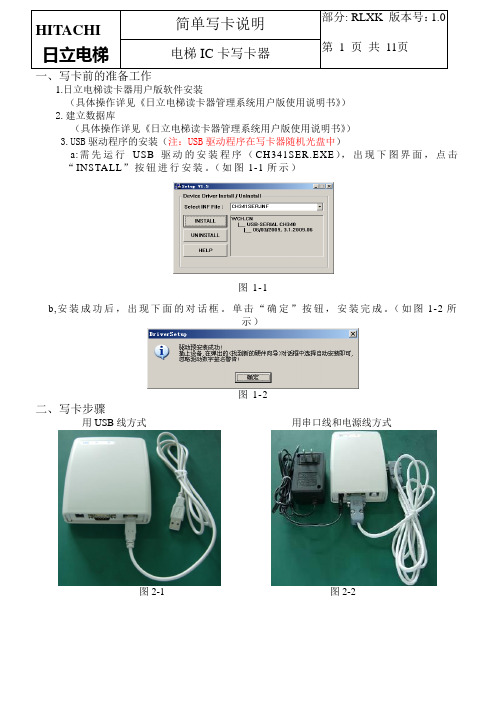
一、写卡前的准备工作1.日立电梯读卡器用户版软件安装(具体操作详见《日立电梯读卡器管理系统用户版使用说明书》)2.建立数据库(具体操作详见《日立电梯读卡器管理系统用户版使用说明书》)B驱动程序的安装(注:USB驱动程序在写卡器随机光盘中)a:需先运行USB驱动的安装程序(CH341SER.EXE),出现下图界面,点击“INSTALL”按钮进行安装。
(如图1-1所示)图1-1b,安装成功后,出现下面的对话框。
单击“确定”按钮,安装完成。
(如图1-2所示)图1-2二、写卡步骤用USB线方式用串口线和电源线方式图2-1 图2-2(1)以USB线方式连接1.打开用户版软件,登录。
(具体操作详见《日立电梯读卡器管理系统用户版使用说明书》)在软件界面选择“参数设置”菜单,选择“选择串口”选项。
选择USB虚拟端口号。
(如图2-3、2-4所示)(注:在登录过程中需要读的授权卡由读卡器管理系统高级版软件发行)图2-3图2-4如何选择虚拟串口:1.将写卡器的USB线插到计算机的USB端口,检测完硬件可用后,点击“计算机—属性—设备管理器”(以下为Windows7系统界面)会出现下面对话框,在“端口(COM和LPT)”中会找到“STM Virtual COM Port (COMX)”(下图中为COM10),此端口就是USB的虚拟COM端口。
(注:连接不同的计算机虚拟COM端口数字不同)(如图2-5所示)图2-52.串口选择完成后,再次读授权卡,发卡界面进入可操作状态。
(如图2-6、2-7所示)图2-6图2-73.点击“卡片管理”菜单(或点击“发行/查询用户卡”按钮),选择“发行/查询用户卡”选项,进入发卡界面。
(如图2-8、2-9所示)图2-8图2-93.1 卡片信息在卡片信息中,包括持卡人的卡号、证件号、电话、姓名、住址。
这些基本信息中“卡号”不能随意更改外,其余都是随意输入的,但不能为空白。
“卡号”既可以由用户输入,也可以由系统自动生成,每次写卡成功后,卡号自动加1。

Page 151 Winthrop RoadChester, Connecticut 06412-0684Phone: (860) 526-9504Internet: Sales e-mail: autosale@Customer Service e-mail: custserv@Configuration Guide:6-button WeCan® Control Head with Slide Switch©2009 Whelen Engineering Company Inc.Form No.14285B (022117)A u t o m o t i v e : S i r e n s /S w i t c h e s®ENGINEERING COMPANY INC.For warranty information regarding this product, visit /warrantyDANGER! Sirens produce extremely loud emergency warning tones! Exposure to these tones without proper and adequate hearing protection, could cause ear damage and/or hearing loss! The Occupational Safety & Health Administration () provides information necessary to determine safe exposure times in Occupational Noise Exposure Section 1910.95. Until you have determined the safe exposure times for your specific application,operators and anyone else in the immediate vicinity should be required to wear an approved hearing protection device. Failure to follow this recommendation could cause hearing loss!•Proper installation of this product requires the installer to have a good understanding of automotive electronics, systems and procedures.•Whelen Engineering requires the use of waterproof butt splices and/or connectors if that connector could be exposed to moisture.•Any holes, either created or utilized by this product, should be made both air- and watertight using a sealant recommended by your vehicle manufacturer.•Failure to use specified installation parts and/or hardware will void the product warranty.•If mounting this product requires drilling holes, the installer MUST be sure that no vehicle components or other vital parts could be damaged by the drilling process. Check both sides of the mounting surface before drilling begins. Also de-burr the holes and remove any metal shards or remnants. Install grommets into all wire passage holes.•If this manual states that this product may be mounted with suction cups, magnets, tape or Velcro®, clean the mounting surface with a 50/50 mix of isopropyl alcohol and water and dry thoroughly.•Do not install this product or route any wires in the deployment area of your air bag. Equipment mounted or located in the air bag deployment area will damage or reduce the effectiveness of the air bag, or become a projectile that could cause serious personal injury or death. Refer to your vehicle owner’s manual for the air bag deployment area. The User/Installer assumes full responsibility to determine proper mounting location, based on providing ultimate safety to all passengers inside the vehicle.•For this product to operate at optimum efficiency, a good electrical connection to chassis ground must be made. The recommended procedure requires the product ground wire to be connected directly to the NEGATIVE (-) battery post (this does not include products that use cigar power cords).•If this product uses a remote device for activation or control, make sure that this device is located in an area that allows both the vehicle and the device to be operated safely in any driving condition.•It is recommended that these instructions be stored in a safe place and referred to when performing maintenance and/or reinstallation of this product.•FAILURE TO FOLLOW THESE SAFETY PRECAUTIONS AND INSTRUCTIONS COULD RESULT IN DAMAGE TO THE PRODUCT OR VEHICLE AND/OR SERIOUS INJURY TO YOU AND YOUR PASSENGERS!CAUTIONLoud siren noise can cause hearing damage and/or loss.Refer to OSHA Section 1910.95prior to putting ANY siren into service!Wear Protection!ACTIVATION OF THIS SIREN MAY DAMAGE UNPROTECTED EARS!Warnings to InstallersWhelen’s emergency vehicle warning devices must be properly mounted and wired in order to be effective and safe. Read and follow all of Whelen’s written instructions when installing or using this device. Emergency vehicles are often operated under high speed stressful conditions which must be accounted for when installing all emergency warning devices. Controls should be placed within convenient reach of the operator so that they can operate the system without taking their eyes off the roadway. Emergency warning devices can require high electrical voltages and/or currents. Properly protect and use caution around live electrical connections.Grounding or shorting of electrical connections can cause high current arcing, which can cause personal injury and/or vehicle damage, including fire. Many electronic devices used in emergency vehicles can create or be affected by electromagnetic interference. Therefore, after installation of any electronic device it is necessary to test all electronic equipment simultaneously to insure that they operate free of interference from other components within the vehicle. Never power emergency warning equipment from the same circuit or share the same grounding circuit with radio communication equipment. All devices should be mounted in accordance with the manufacturer’s instructions and securely fastened to vehicle elements of sufficient strength to withstand the forces applied to the device. Driver and/or passenger air bags (SRS) will affect the way equipment should be mounted. This device should be mounted by permanent installation and within the zones specified by the vehicle manufacturer, if any. Any device mounted in the deployment area of an air bag will damage or reduce the effectiveness of the air bag and may damage or dislodge the device. Installer must be sure that this device, its mounting hardware and electrical supply wiring does not interfere with the air bag or the SRS wiring or sensors. Mounting the unit inside the vehicle by a method other than permanent installation is not recommended as unit may become dislodged during swerving; sudden braking or collision. Failure to follow instructions can result in personal injury. Whelen assumes no liability for any loss resulting from the use of this warning device. PROPER INSTALLATION COMBINED WITH OPERATOR TRAINING IN THE PROPER USE OF EMERGENCY WARNING DEVICES IS ESSENTIAL TO INSURE THE SAFETY OF EMERGENCY PERSONNEL AND THE PUBLIC.Warnings to UsersWhelen’s emergency vehicle warning devices are intended to alert other operators and pedestrians to the presence and operation of emergency vehicles and personnel. However, the use of this or any other Whelen emergency warning device does not guarantee that you will have the right-of-way or that other drivers and pedestrians will properly heed an emergency warning signal. Never assume you have the right-of-way. It is your responsibility to proceed safely before entering an intersection, driving against traffic, responding at a high rate of speed, or walking on or around traffic lanes. Emergency vehicle warning devices should be tested on a daily basis to ensure that they operate properly. When in actual use, the operator must ensure that both visual and audible warnings are not blocked by vehicle components (i.e.: open trunks or compartment doors), people, vehicles, or other obstructions. It is the user’s responsibility to understand and obey all laws regarding emergency warning devices. The user should be familiar with all applicable laws and regulations prior to the use of any emergency vehicle warning device. Whelen’s audible warning devices are designed to project sound in a forward direction away from the vehicle occupants. However, because sustained periodic exposure to loud sounds can cause hearing loss, all audible warning devices should be installed and operated in accordance with the standards established by the National Fire Protection Association.Safety FirstThis document provides all the necessary information to allow your Whelen product to be properly and safely installed. Before beginning the installation and/or operation of your new product, the installation technician and operator must read this manual completely. Important information is contained herein that could prevent serious injury or damage.WARNING: This product can expose you to chemicals including Lead which is known to the State of California to cause cancer and birth defects or other reproductive harm. For more information go to .Page 2Notes:1)TD/AUX =Takedown /Auxiliary Take-Downs or Worklights2)Some configurations will allow specific buttons to activate alternate functions with each press of that button. In the artwork shown,these buttons are represented with white letters on a black background. In these cases, the functions to be activated are shown in sequential order and are separated with a horizontal line.Dip Switch Configuration #1Dip Switch Configuration #2Dip Switch Configuration #3California Title13 compliantOn Off1ON23412,3,4On Off1ON23421,3,4On Off1ON2342,31,4On Off1ON23441,2,3On Off1ON2341,2,43On Off1ON2343,41,2On Off1ON2341,23,4On Off1ON2341,2,34On Off 1ON2341,42,3Pos.1 -T/A LeftPos.1 -T/A LeftPos.1 -T/A LeftPos.2 -T/A SplitPos.2 -T/A Split Pos.2 -T/A SplitPos.3 -T/A Right Pos.3 -T/A Right Pos.3 -T/A Right L Alley R AlleyLight Bar CruiseFront Cutoff Patrn Over-rideTD/AUXMode 1Front Cutoff Mode 2Low PowerPatrn Over-rideTD/AUXMode 1Low PowerFront CutoffMode 2Mode 3TD/AUXCruise TD/AUXTA RightL Alley R AlleyTA Left TA Split L Alley R AlleyTA Left TA Split Patrn Over-rideTD/AUXTA RightPatrn Over-rideTD/AUXOn Off1ON23431,2,4On Off1ON2341,32,4Dip Switch Configuration #4Dip Switch Configuration #7Dip Switch Configuration #10Pos.1 -All Bar 1Pos.1 -FrontPos.1 -FrontPos.1 -FrontPos.1 -FrontPos.1 -RearPos.1 -FrontPos.1 -All Bar 1Pos.1 -All Bar 1Pos.2 -All Bar 2Pos.2 -RearPos.2 -RearPos.2 -RearPos.2 -Rear Pos.2 -FrontPos.2 -RearPos.2 -All Bar 2Pos.2 -All Bar 2Pos.3 -All Bar 3Pos.3 -All Pos.3 -All Pos.3 -All Pos.3 -All Pos.3 -All Pos.3 -All Pos.3 -All Bar 3Pos.3 -All Bar 3Dip Switch Configuration #5Dip Switch Configuration #8Dip Switch Configuration #11Dip Switch Configuration #12Dip Switch Configuration #6Dip Switch Configuration #9TA Left TA SplitTD/AUXL Alley R AlleyLow Power Front CutoffRear Cutoff TA RightTA Left Low PowerFront CutoffTA Split TA RightTD/AUXL Alley R AlleyTA Left TA Split TD/AUXTA RightLow PowerL Alley R AlleyTA Left TA Split Front FlashTD/AUXTA RightTA Left TA SplitL Alley R AlleyPatrn Over-rideCruise TD/AUXTA RightOn Off1ON2342, 41, 3Front TA Left Rear TA RightFront TA RightLeft Alley Right AlleyRear TA Left Flash Alley TD Left Alley Right AlleyCruise Secure the mounting plate to the control head using the supplied 4 X 1/4 PFH Plasti-Loc screws.NOTE: Dip switches are located on the back of the unit.1.Secure the controller to the mounting surface using the supplied 6 X 1/2" PPHSMS.Extend the wires and connect as described below.Installation:2.3.WARNING!All customer supplied wires that connect to the positive terminal of the battery must be sized to supply at least 125%of the maximum operating current and at the battery to carry the load.DO NOT USE CIRCUIT BREAKERS WITH THIS PRODUCT!FUSED BLK RED WHTGRN GRYto +12VDC Fuse (3A)Fuse (1A)4-1/4 PFH Plasti-Loc Screw (qty. 4)Mounting Plate4-1/2 PPHSMS (qty. 2)to +12VDC ignition controlled circuit (Backlight)to Groundto WeCan® Lightbar。

TCD-720/820-M发卡器用户手册版本 2.00深圳市德立达科技有限公司地址:深圳市南山区沙河西路茶光工业园二栋4楼C座电话:86-755-33019266 传真:86-0755-********网址: E-mail: chinatenet@ chinatenet@目录一、主要特性 (3)二、主要技术指标 (3)三、控制接口 (4)3.1 电平控制接口定义 (4)3.2 RS232控制接口定义 (4)3.3 控制说明 (5)3.4 接口电路示意图 (6)3.5 RS232C通讯协议 (6)四、发卡器的工作状态指示 (9)五、操作和维护 (9)5.1 发卡器的安装 (9)5.2 发卡器的拆卸 (9)5.3 怎样往卡箱内加卡 (10)5.4 发卡器卡片厚度调节 (10)5.5 发卡器的日常维护和保养 (11)六、安全使用注意 (11)一、主要特性●工业级设计,耐磨耐腐蚀,适应各种高温多尘的恶劣环境;●模拟人手的摩擦式发卡,对各类变型卡有较强的适应性;●硬件看门狗、嵌入式微型实时操作系统保证系统可靠运行;●预发卡功能加快发卡速度,缓解车辆排队问题;●可直接连接地感性号,实现“车来发卡、一车一卡”;●卡少、卡空、故障时自动声音报警;●出错报警100秒后自动复位;●提供RS232和I/O电平两种控制接口;●卡片回收容量可达40多张,并有卡满声音报警功能;●特别加强安全回收功能,防止恶意丢卡(仅TCD800系列);●可叠加的卡箱设计,使卡箱容量灵活可变;●卡片厚度在0.3mm―2.5mm内可调节(出厂时卡厚设为0.8mm);●滑轨式安装设计,使发卡器安装和拆卸更简单、方便、快捷;●全模具化生产,高度保证产品精度和品质的一致性;二、主要技术指标●工作电源:24VDC(最大电流2A,静态电流0.1A)●工作温度:-20℃ to 85℃●工作湿度:30-90% (相对湿度)●使用条件:安装在箱柜中使用●适用卡片尺寸卡宽 : 54±0.5 mm卡长: 85±0.5 mm卡厚: 0.3– 2.5 mm(可调节)(注:出厂时设为0.8mm)●适用卡片材料:各类纸质卡片或聚脂类卡片。
文档编号: ZH-22WI-999012 版 本 号: 3.0非接触式IC 卡计时宝(SMTMJMF-V22)用 户 手 册广东智慧电子信息产业股份有限公司“智慧牌”非接触式IC 卡产品系列SMART CARD & IT SERISE®文档摘要项目名称:“智慧牌”非接触式IC卡计时宝文档编号:ZH-22WI-999012文档编写者:出版日期:参考文献:《智慧“一卡通”信息管理系统需求分析说明书》、《智慧“一卡通”信息管理系统概要设计说明书》、《GB/T18239-2000集成电路(IC)卡读写机通用规范》和《GB 4208 外壳防护等级的分类》《GB 6587.7 电子测量仪器基本安全试验》,《GB 191 包装储运图示标志》《GB 6833.5 电子测量仪器电磁兼容性试验规范辐射敏感度试验》《GB 6833.3 电子测量仪器电磁兼容性试验规范静电放电敏感度试验》等文档更新记录表内容简介“智慧牌”非接触式智能卡计时宝融合了美国、日本、西欧、香港、台湾以及中国大陆各类型企事业单位的时间管理模式特点,将通用性与智能化有机结合,可视不同的使用需求而设定相应时间管理参数。
计时宝广泛适用于考勤、门禁、巡更、会议签到、钟点记录等计时、监控功能管理,可同时控制多组外控设备,接受多组输入信号,共有四种不同的工作模式供客户选择使用,适用卡片型号为Mifare One卡、CPU卡和ID卡,是企事业单位最好的时间“管家婆”。
套装形式的“计时宝”,出厂时已配齐了安装使用的必备配件,您仅需按照本说明书传授的方法,就能十分方便地掌握,并自行完成系统的安装、设置和查询。
与之配套的软件有考勤、门禁、人事、工资等管理软件,为您解决一般性的事务管理工作,如有特殊需求可与当地经销商联系,委托开发制作。
计时宝具有操作简便,安全可靠,功能实用,快速精确等特点。
在本说明书中,详细的对计时宝做了介绍,包括外观注释、产品特性、键盘介绍、配件介绍、连接器参数、连线转换盒参数和技术参数;还详尽的介绍了计时宝的安装与检测、使用方法、网络连接;最后还列出了报警代码和纠错措施以及技术支持联络方法。
键盘操作说明书管理员密码初始为200512 (进入编程状态如果10秒钟之内,没有任何编程指令,系统自动退出编程,进入正常工作状态),如果为首次出厂使用请热复位系统初始化密码。
1.按* => 管理员密码=> #,红灯闪烁表示进入编程状态。
按* => 管理员卡,红灯闪烁表示进入编程状态。
2.按0 => 新密码=> 重复新密码=> # ,修改成功,退出通讯模式。
3.按1 => 2位楼层数=> 2位权限组=>6位有效期(年月日输入000000表示不启用)=> 4位有次数(输入0000表示不启用)=> # ,连续刷卡可添加多张同楼层、同密码用户卡,提示“嘟”声,添加用户卡成功。
如果需要添加不同楼层、不同密码用户卡,只需要按“#”,返回上级操作,重新按1 => 2位楼层数=> 6位有效期(年月日)+2位权限组=> # ,然后刷用户卡,添加完成后按“*”即可退出编程模式。
简化输入:按1 => 2位楼层数=> 2位权限组=> # 不启用有效期与有效次数。
4.删除用户卡片:删除可读卡:按2 => 999999 => # => 连续刷卡可删除多张卡片,操作成功,提示“嘟”声。
删除卡号卡:按2 => 10位用户卡号=> # 操作成功,提示“嘟”声。
5.设置有效模式:①读卡有效:按3 => 1 => #②卡加密码:按3 => 2 => #③读卡或者密码开门:按3 => 3 => # 操作成功,提示“嘟”声。
注意:出厂设置为33,读卡或者密码开门。
6. 设置系统参数:读卡器类型:按4 => 0 => # 恢复设备为自动检测读卡器类型。
读卡器指示灯极性:按4 => 1 => 极性值=> # 极性值:1为共阴、0为共阳继电器刷卡动作时间:按4 => 2 => 3位数动作时间(不足补0)=> #读卡间隔时间:按4 => 3 => 3位数间隔时间(不足补0)=> #需首卡开门:按4 => 4 => 模式=> # 模式:0为不需要首卡1为需要首卡提醒日期:按4 => 5 => 2位提醒天数=> #读卡器1绿灯接线用做到期提醒。
M-2000(A)专业参量移频反馈抑制器说明书在室内扩声中,从扬声器发出的信号以及从建筑物反馈的信号返回拾音器与原始信号叠加,再度经由系统放大、叠加,如此周而复始地循环往复,形成振荡,表现为声反馈(啸叫声),从而破坏了扩声系统的稳定性。
严重时根本无法扩声,这一直是令音响专家们头疼的难题。
我公司一直致力于研制和生产声反馈抑制设备。
一直以来人们对移频器存有偏见,因为传统移频器难以避免“低频颤抖”失真现象和“染色”效应;况且,频率的移动本身即意味着信号失真,由于人耳的特性决定了对其频率失真较为敏感,所以在低频部分的频率变化几乎人人可以感觉;且让人难以接受,由于原理以及电路缺陷几十年来并未取得突破性进展。
随着科学技术的进步,在新纪初期,国际上相继出现了很多新技术,如专用计算机的应用使得移频技术有飞跃的发展,基本克服了“颤抖”和“染色”效应。
本公司吸取国际国内众家之所长,结合多年DSP和数字电路开发和应用实际经验加以提升,终于开发成功超宽频响全数字移频器,是传统移频器的革命,该产品已申请国家专利。
M-2000产品一举改变了人们对移频器的偏见,人耳听感频响良好,基本无法分辨出是否移频,无传统移频器的变音、音窄、尾音、发抖等现象。
M-2000(A)专业参量移频器是本公司研发的专业解决会议室、大型歌剧院、教学、公共演讲、KTV 演绎厅等场合容易啸叫(声反馈)、话筒声音小不能开大,或因设备原因或建声环境等引起的易发生声反馈缺陷的功能性产品。
M-2000(A)专业参量移频器采用了以下防啸叫措施:1.采用超宽频响高保真全数字移频器专利技术,是传统移频器的革命,采用主动式防啸叫技术,使输出的峰点与反馈频率的峰点不是同一频率,从而抑制了反馈的产生。
2.采用五个独立三波段全频宽衰减式参量均衡器电路,可对音频全区域频率进行扫频,衰减峰值反馈频率,进一步提升系统整体增益。
M-2000(A)专业参量移频器具有以下特点:1、防啸叫效果显著:由于采用了五段参量+数字移频两重防啸叫技术,防啸叫效果显著。
PCS C OMBINATION S ENSOR WITH D ISPLAY75 Discovery Way•Acton, MA 01720 USA •Tel (978) 795-1285•Fax (978) 795-1111•©2020 Phoenix Controls. Specifications subject to change without notice. Rev. 04/2021 MKT-0442MPC-2606PCS C OMBINATION S ENSOR WITH D ISPLAY1Phoenix Controls temperature sensors provide a stable and secure environment for those facilities that need it the most, such as hospitals, cleanrooms, and laboratory animal facilities. The sensors also simplify room balancing by eliminating the need for a certified person to accompany the balancer during the commissioning process.The PCS4xx/5xx/6xx series, microprocessor-based sensor, provides a choice of three temperature sensor output signal signals and three humidity sensor output signals. The five pushbuttons allow easy adjustment of set points, occupancy override, and access to the setup menu. The large backlit LCD display allows simultaneous display of two values (temperature, temperature set point, humidity, or humidity set point) and occupancy status.Features •Test and Balance in the setup menu for heating, cooling, and normal operation •Fully configurable set point range, relative or absolute•Large Backlit LCD Display with readings within a tenth of a degree •Simultaneous display of temperature, humidity, and occupancy status •3.5 mm communications jack (standard)•Foam backing for drywall or 2" x 4" single gang junction box mounting (standard)•Optional 3 Point NIST Calibration CertificatesSPECIFICATIONSSpecificationTemperatureHumidity4xx Series5xx Series6xx Seriesx05/x10/x20 SeriesSensor Output Range (Span)32-122 °F (0-50 °C)40-104 °F (5-40 °C)32-122 °F (0-50 °C)0-100%Sensing Element Thermistor (NTC)Platinum RTD (PTC)Thermistor (NTC)Impedance T ype Humidity Sensor Signal, Sensor Output(Common Ground)10 K Type 2 thermistor 0-10 Vdc20K NTC0 to 5 Vdc, or 0 to 10 Vdc, or 4 to 20 mAKeypadConfiguration 5 Pushbuttons (Setup, Up and Down Arrows, O/R (Occupancy Override), and Select)Signal, Set Point Output(Common Ground)0-20K ohms0-10 Vdc9.5-1K ohms0 to 5 Vdc, or 0 to 10 Vdc, or 4 to 20 mALocal Occupancy Control Contact closure to common groundDisplay Blue backlight LCD, 2.27”x 1.7”, 3 LED, programming option for 0 or 1 decimal point Display Unit of MeasurePush Button Programming (°F (standard) or °C)Setpoint Display and Range(Push Button Control & Programming)Fully configurable via pushbutton menu:- Setpoint range: 55 to 89 °F (15 to 31 °C)- Setpoint Adjust: adjustable up to -20 to +20 °F or °C of setpoint (1 °F or0.5 °C increments)- Setpoint Limits: 40 to 104 °F (4.5 to 40 °C)- Relative range: up to -20 to 20 ° F or °C (1 °F or 0.5 °C increments)Fully configurable via pushbutton menu:- Setpoint range: 33 to 67%- Setpoint Adjust: adjustable up to -20% to +20% of setpoint (1% increments)- Setpoint Limits: 13% to 87%Occupancy Display Remote contact closure to common ground indicates Occupied on display Housing Material/ColorABS/PC (White); UL 94-5VBPCS Combination Sensor2 PCS C OMBINATION S ENSOR WITH D ISPLAY MKT-0442 MPC-2606 ©2020 Phoenix Controls. Specifications subject to change without notice. Rev. 04/2021DIMENSIONSTest & BalanceSettings(Push Button Control) 40 °F (4.4 °C), 72 °F (22.2 °C), and 104 °F (40 °C)0%, 50%, and 100%Communication Jack 3.5 mm Stereo Jack (Ring, Tip, Shield)Operating Range 35-122 °F (1.5-50 °C), 0-95% Relative Humidity Non-Condensing Storage Range -4-131 °F (-20-60 °C), 0-95% Relative Humidity Non-Condensing Reference Resistance 10K ohm @ 77 °F (25 °C)1K ohm @ 32 °F (0 °C)20K ohm @ 77 °F (25 °C)N/AAccuracySensor Output Accuracy: +/- 1.0 °F (+/- 0.56 °C): LCD Display Accuracy +/- 1.5 °F due to Rounding2% from 10 to 95% RH @ 77 °F (25 °C)Dissipation Constant N/AResponse Time 10 seconds nominal for a 63% step increase (room-hot water)11 seconds nominal for a 63% step decrease (room-ice water)20 seconds for a step of 46%-96%45 seconds for a step of 98%-47%Stability < 1% after 1000 hours at 212 °F (100 °C)N/A< 1% after 1000 hours at 212 °F (100 °C)< 2% over 5 years Supply Voltage +18 to 40 Vdc (NOTE: Use of PVC400-HW is required for LON applications)Power Consumption < 0.65 VA (x05 and x10 Series), < 4 VA (x20 Series)Product Dimensions (L x W x D) 4.56" (115.82 mm) x 3.0" (76.2 mm) x 1.45" (36.75 mm)Product Weight 0.35 lbs (0.162 kg)NIST Certification (6 Points)61 °F (16 °C), 72 °F (22.5 °C), and 82 °F (28 °C)20%, 50%, and 80% @ 72 °F (22 °C)Regulatory ComplianceSpecificationTemperatureHumidity4xx Series5xx Series6xx Seriesx05/x10/x20 SeriesWEEE Directive 2012/19/ECWaste Electrical and Electronic Equipment directiveAt the end of the product life dispose of the packaging and product in a corresponding recycling centre. Do not dispose of the unit with the usual domestic refuse. Do not burn the product.EU Contact Address:Pittway Tecnologica Srl Via Caboto 19/334147 Trieste TS Italy©2020 Phoenix Controls. Specifications subject to change without notice. Rev. 04/2021 MKT-0442 MPC-2606PCS C OMBINATION S ENSOR WITH D ISPLAY 3ORDERING GUIDEValid Catalog NumbersOUTPUT FORMULAS AND TABLESFor output formulas and complete sensor output tables, see MKT-0474 Sensor Outputs and T ables .PHX-COMBINATION-SENSOR (10K-2 Temperature Output)PHX-COMBINATION-SENSOR (0-10VDC Temperature Output)PHX-COMBINATION-SENSOR (20KTemperature Output)Catalog Number without CalibrationCertificate Catalog Number with 6 Point CalibrationCertificate Catalog Number without CalibrationCertificate Catalog Number with 6 Point CalibrationCertificate Catalog Number without CalibrationCertificate Catalog Number with 6 Point CalibrationCertificate PCS405-R-DOP PCS405-R-DOP-06PCS505-R-DOP PCS505-R-DOP-06PCS605-R-DOP PCS605-R-DOP-06PCS405-R-DHOP PCS405-R-DHOP-06PCS505-R-DHOP PCS505-R-DHOP-06PCS605-R-DHOP PCS605-R-DHOP-06PCS410-R-DOP PCS410-R-DOP-06PCS510-R-DOP PCS510-R-DOP-06PCS610-R-DOP PCS610-R-DOP-06PCS410-R-DHOP PCS410-R-DHOP-06PCS510-R-DHOP PCS510-R-DHOP-06PCS610-R-DHOP PCS610-R-DHOP-06PCS420-R-DOP PCS420-R-DOP-06PCS520-R-DOP PCS520-R-DOP-06PCS620-R-DOP PCS620-R-DOP-06PCS420-R-DHOPPCS420-R-DHOP-06PCS520-R-DHOPPCS520-R-DHOP-06PCS620-R-DHOPPCS620-R-DHOP-06。
TCD-720/820-M发卡器用户手册版本 2.00深圳市德立达科技有限公司地址:深圳市南山区沙河西路茶光工业园二栋4楼C座电话:86-755-33019266 传真:86-0755-********网址: E-mail: chinatenet@ chinatenet@目录一、主要特性 (3)二、主要技术指标 (3)三、控制接口 (4)3.1 电平控制接口定义 (4)3.2 RS232控制接口定义 (4)3.3 控制说明 (5)3.4 接口电路示意图 (6)3.5 RS232C通讯协议 (6)四、发卡器的工作状态指示 (9)五、操作和维护 (9)5.1 发卡器的安装 (9)5.2 发卡器的拆卸 (9)5.3 怎样往卡箱内加卡 (10)5.4 发卡器卡片厚度调节 (10)5.5 发卡器的日常维护和保养 (11)六、安全使用注意 (11)一、主要特性●工业级设计,耐磨耐腐蚀,适应各种高温多尘的恶劣环境;●模拟人手的摩擦式发卡,对各类变型卡有较强的适应性;●硬件看门狗、嵌入式微型实时操作系统保证系统可靠运行;●预发卡功能加快发卡速度,缓解车辆排队问题;●可直接连接地感性号,实现“车来发卡、一车一卡”;●卡少、卡空、故障时自动声音报警;●出错报警100秒后自动复位;●提供RS232和I/O电平两种控制接口;●卡片回收容量可达40多张,并有卡满声音报警功能;●特别加强安全回收功能,防止恶意丢卡(仅TCD800系列);●可叠加的卡箱设计,使卡箱容量灵活可变;●卡片厚度在0.3mm―2.5mm内可调节(出厂时卡厚设为0.8mm);●滑轨式安装设计,使发卡器安装和拆卸更简单、方便、快捷;●全模具化生产,高度保证产品精度和品质的一致性;二、主要技术指标●工作电源:24VDC(最大电流2A,静态电流0.1A)●工作温度:-20℃ to 85℃●工作湿度:30-90% (相对湿度)●使用条件:安装在箱柜中使用●适用卡片尺寸卡宽 : 54±0.5 mm卡长: 85±0.5 mm卡厚: 0.3– 2.5 mm(可调节)(注:出厂时设为0.8mm)●适用卡片材料:各类纸质卡片或聚脂类卡片。
●发卡器净重: 2.0Kg(含压卡块)●出卡时间:最快约0.5秒。
●卡箱容量:150张(按卡厚0.8mm计算),每加长一级可增加100张。
三、控制接口发卡器提供电平I/O控制接口和RS232接口。
I/O电平控制接口由控制板上标准12Pin(2.54mm)插座CN3引出,RS232接口由3Pin(2.54mm)插座CN7引出.3.1 电平控制接口定义(CN3)3.2 RS232控制接口定义(CN7)3.3 控制说明1、复位和自动回收当发卡机复位时,首先会“嘟、嘟”响两声以表明正在自检。
如果检测到堵卡,则会自动将卡片回收至卡仓中;如果自检正常,则会驱动马达转动尝试预发卡操作。
有以下几种情况会导至发卡机复位:①当发卡机上电时会产生复位操作;②当发卡机收到Reset信号或按下控制板上的Reset按键时;③当发生预发卡(失败)错误时,如果超过100秒发卡器会自动复位;④当发生堵卡错误时,如果超过100秒发卡器会自动复位并将卡片收回;卡片回收主要是避免卡片在使用过程中被丢失,最大程度地减少物业的损失。
在以下几种情况,发卡器会自动将卡片收回:①在复位时,如果发卡器前端有卡(即堵卡)则自动回收;②在预读发卡模式,当卡片送至读卡位置超过100秒时卡片将被自动回收;③无论何种模式,当卡片送至取卡位置超过100秒时卡片将被自动回收;④卡片处于读卡或取卡位置时,发卡器收到CallBack信号则将卡片回收。
2、错误输出与处理有三种情况会导致ERROR信号的输出:①在发卡器预发卡时,如果反复五次均未将卡片发出,即预发卡失败时(蜂鸣器响“嘟、嘟、嘟”三短声);②当发卡器检测到前向通道中有卡片堵塞时(蜂鸣器响“嘟、嘟”两短声);③当发卡器检测到回收仓中卡片已装满时(蜂鸣器响“嘟、嘟、嘟、嘟”四短声)。
当发生预发卡失败时,在输出ERROR信号100秒后发卡器会自动复位并清除ERROR信号;当堵卡或卡满时只要取走卡片,ERROR信号即可自动清除(ERROR信号置高);若堵卡未及时清除,在100秒后发卡器会自动复位并清除ERROR信号。
当用户主机检测到发卡器有ERROR信号输出时,可以通过RESET信号使发卡器复位。
正常情况下,复位后超时错误可以被清除,前向通道上的卡片也可以被自动回收到卡仓中,但当回收仓卡片已满时仍会输出ERROR信号。
因此,若在复位后仍有ERROR信号输出,则用户主机应提醒操作人员检查发卡器是否回收仓已装满或是否有其它故障。
3、OUTOK输出方式设置OUTOK信号的输出有两种方式,由CN9的DIP2设置。
当DIP2=ON时,OUTOK输出为取卡信号,即当卡被取走时,输出300mS的低电平脉冲;当DIP2=OFF时,OUTOK输出为卡片到位信号,表示卡片被送至读卡位置或取卡位置。
4、发卡方式设置发卡器有两种发卡方式:预读发卡方式和直接发卡方式。
这由发卡器控制板上的拔码开关CN9的DIP1来设置。
以下假定OUTOK被设为到位信号(DIP2=OFF)来详细说明两种发卡方式。
预读发卡方式:DIP1=ON时,发卡器为预读发卡方式。
在此方式,输入Payout信号且VD信号有效时,发卡器会将卡片发送至读卡天线位置,并拉低OUTOK信号等待用户读卡。
此时,如果收到回收信号,则将卡片回收并将OUTOK信号置高;如卡机再次收到Payout信号,则置高OUTOK信号并将卡片发送至出卡口,然后再次将OUTOK信号拉低,直到卡片被取走才将OUTOK信号置高。
直接发卡方式:DIP1=OFF,DIP2=OFF时,发卡器为直接发卡方式。
在此方式,输入Payout信号且VD信号有效时,发卡器会将卡片直接发送至出卡口,同时将OUTOK信号置低,直到卡片被取走才将OUTOK信号置高。
3.4 I/O电平控制接口电路示意图3.5 RS232C 通讯协议发卡器与主机之间的通讯采用标准的8位异步数据传送格式。
3.5.1 数据传送格式 编 码: NRZ 波特率: 9600双 工: 半双工 数据位: 8位较验位: 无停止位: 1位3.5.2 主机命令帧格式命令帧格式: <STX> □ □ <ETX> <BCC> <STX> : 02(HEX ),命令帧开始 □ □ : 操作命令,为两字节ASCII 码 <ETX> : 03(HEX ),命令帧结束<BCC> : <STX>@□@□@ <ETX>,命令块异或校验码(@为异或运算符) 3.5.3 主机操作命令主机向发卡器发送以下命令,并执行相关操作。
以下命令代码示例全用十六进制(用前缀0x 表示)代码给出。
发卡命令代码:0x02,0x44,0x43,0x03,0x06 回收命令代码:0x02,0x43,0x50,0x03,0x12 查询命令代码:0x02,0x52,0x46,0x03,0x15 复位命令代码:0x02,0x53,0x54,0x03,0x06当用户主机发送一帧命令后,发卡器会返回ACK 信号(0x06)或NAK 信号(0x15),如收到ACK (0x06)信号,主机应再发送一字节的ENQ (0x05)信号,发卡器方能执行收到的命令。
3.5.5 发卡器应答命令 3.5.5.1 应答命令帧格式输出端口电路所有输出信号都是开集电极方式输出,最大输出为24V @100mA ,输出最少保持200毫秒。
输入端口电路所有输入信号低电平有效,且最小保持200毫秒,输入去抖动时间设为50毫秒。
应答命令帧:<STX> □ □ □ <ETX> <BCC> <STX> : 0 2 (HEX) , 命令帧开始 <ETX> : 0 3 (HEX) , 命令帧结束 □□□:发卡器状态码信息,ASCII 码格式<BCC> : <STX>@‘S’@‘F’@□@□@□@<ETX>,命令块异或校验码注:@为异或运算符。
3.5.5.2 发卡器状态码描述3.5.6 主机与发卡器通讯时序 3.5.6.1 发卡命令时序主 机: “DC” ENQ 发卡器:ACK/NAK <执行发卡操作>3.5.6.2 回收命令时序主 机: “CP” ENQ 发卡器: ACK/NAK <执行收卡操作>3.5.6.3 状态查询命令时序主 机: “RF” ENQ 发卡器: ACK/NAK“SF□□□” 3.5.6.4 复位命令时序主 机: “ST” ENQ 发卡器: ACK/NAK<执行复位>注: ACK代码为06(HEX),NAK代码为15(HEX),ENQ代码为05(HEX)。
四、发卡器的工作状态指示在发卡器的控制板上的红色LED亮表明电源状态,蜂鸣器输出则表明发卡机的各种工作状态(见下表)。
用户可通过听声音来判断发卡器是否有故障:“一少五空,二堵三错,四收满。
”五、操作和维护5.1 发卡器的安装在使用发卡器时,你可按以下方法将发卡器方便快捷地安装到你的机箱中。
首先参照导轨底板的安装孔位在票箱底板上正对出卡口中心线适当的位置钻取两个直径为3mm的安装孔,然后将导轨底板(用镙钉和镙母并加垫圈)固定在票箱底板上并调整好其前后的距离,最后将发卡器插入导轨底板并将发卡器尾部两侧的销紧镙钉拧紧销住发卡器。
这样发卡器就已经安装好了,再将信号连线插入发卡器后面的插座,接通电源即可检验发卡机是否已装好。
5.2 发卡器的拆卸在调试和维护时,你可以按以下方法将发卡器轻松地从你的机箱中拆下来。
首先关闭电源打开机箱,拔下发卡器尾部的连接插头,然后用十字镙丝刀松开发卡器尾部两侧的锁紧镙钉,沿底板导轨向后轻轻拉动发卡器,即可将其拆下。
5.3 怎样往卡箱内加卡当机器发出空卡或卡量少报警时,值勤人员应按以下要求向卡机的卡箱中加入足够的卡片以保证系统的正常运作。
1、首先,请确保所加卡片厚度与发卡器的卡厚要求相匹配(卡厚要求记录在发卡器侧板的标签上),如卡厚不符请你立即联络维护人员(未经正式培训合格的人,请不要随意校调出卡厚度)。
2、加卡时请遵从以下顺序:打开机箱――关闭电源――取出压卡铁块――将卡片一叠一叠地平放入卡箱内――最后一定要放入压卡铁块――然后检查发卡器传动机构并确保其安全性――开电源――关机箱。
5.4 发卡器卡片厚度调节为了适应不同厚度的卡片,发卡器的厚度是可调节的。
由于卡厚调节的好坏影响到发卡器的整机性能,所以不仅要求操作人员按以下的方法操作,而且还要求操作人员对此过程要进行反复多次的演练,深切体会每一步骤的要领。