TND系列高精度全自动单相交流稳压电源
- 格式:pdf
- 大小:394.00 KB
- 文档页数:2
a)输入电压表◎显示输入电压b)输出电压表◎显示输出电压c)输入电压选择若输入电压稳定,请弹出"输入"按钮,以提高稳压器的带载能力;若输入电压不稳定,请按下"输入"按钮,以降低带载能力。
d)延时、非延时选择若该稳压器配备制冷设备使用,请选择"延时保护",以降低对制冷压缩机造成损耗的几率。
若不是配合该类设备使用,则选择"非延时保护"。
e)电源开关这是稳压器的电源总开关。
f )指示灯1)工作指示灯工作指示灯亮,表明稳压器正常工作。
2)过压指示灯过压指示灯亮,输出电压超过246±4V,电路保护启动,稳压器无电压输出。
当输出电压下降到246±4V以下,稳压器再次启动输出电压。
3)延时指示灯延时保护状态下,指示灯闪烁,延时保护结束,指示灯熄灭。
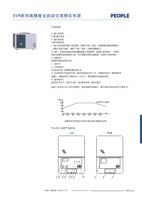
产品结构LED彩屏请确保所带负载总功率不超过稳压器额定功率。
若输入电压在190-250V范围内,稳压器满功率输出,最大输出功率走势如下图所示。
TR-LED/彩屏产品结构046①②③④⑤⑥⑦⑧⑨⑩1. 过压2. 欠压3. 过温4. 过载5. 输出电压6. 输入电压7. 功率曲线8. 延时9. 正常10. 保护LED彩屏1.显示屏(LED / 彩屏)2.电压转换3.延时转换4.接线盖5.过压6.工作7.市电 稳压8.延时9.接线圈10.散热孔技术参数047SVR-LED/彩屏产品结构1.过压灯2.工作灯3.延时灯4.显示屏(LED / 彩屏)5.开关6.延时按钮7.过载保护按钮8.散热孔9.接地10.输入电源线11.保险丝12.220V输出SVR-1000VA/1500VA/2000VA45670481.过压灯2.工作灯3.延时灯4.显示屏(LED / 彩屏)5.市电稳压6.延时按钮7.过载保护按钮8.散热孔9.提手扣10.接线孔11.接线盖SVR-3000VA/5000VA/8000VA/10000VA9. 正常10. 保护1.过压2. 欠压3. 过温4. 过载5. 输出电压6. 输入电压7. 功率曲线8. 延时③④⑦⑩①②⑤⑥⑧⑨彩屏LED过压工作延时技术参数彩屏显示模式如下表延时:机器启动时,短延时5秒,倒计时之后机器正常工作。
上海稳利达电气有限公司S H A N G H A I W E N L I D A E L E C T R I C C O ., L T D .上海稳利达科技股份有限公司S H A N G H A I W E N L I D A T E C H N O L O G Y .,L T D产品说明书Compensation AC stabilizerProduct descriptionSBW•DBW series automatic compensating alternative stabilizers are new products with voltage stable and protect functions, this product combining the mostadvanced European technology with our national condition.When the fluctuation of voltage occurs or load changes,it can automatically keep the stability of the output voltage.These series prod-ucts have the advantages of large capacity,high efficiency.small waveform deformation,smooth voltage regulation.wide range of load,the ability of undertaking instant overload,longterm continuous operation, manual & automatic control mode, protective function of overvoltage, short circuit and mechanical transmission failure.small volume and weight.easy and convenient usage,and reliable opera-tion.etc.These series products are widely used in the places requiring stable voltage such as in industry,agriculture,transportation,military, railway, postal offices, and scientific research institutes, which are includinglarge industrial production line, medical devices.architectural equipments.testing equipments,broadcast and TV stations, telecom statiions, air-conditional computer rooms, etc.Product descriptionChapter I overview1、TypeThis series of stabilizers' model shown in the figure:Rated capacity (KVA)Design StabilizerCompensating deviceS:three-phaseD:single-phaseB w2、Host machine and main components��Chapter I overview��Chapter I overviewSBW·DBW series stabilizer should be used indoors,normal conditions are as follows ① Temperature: -15~+45℃ ② Altitude: ≤1000m; ③ Relative Humidity: ≤90%;④ Installation position: no such materials serious effects on the Insulation of stabiliz-er, as gases,steam, chemical deposition, dust, dirt, and other explosive and erosive medium; ⑤ There is no serious fluctuation in installation position;⑥ If any of above conditions are not satisfied, it is suggested that user and WENLIDAarrange the installation.4、operation condition5、Working principles��Chapter I overviewStabilizer includes compensating circuit, voltage inspection circuit, feedback loop,servo-motor circuit and deceleration driving circuit, mainloop switch circuit,voltage and current measurement loop, and protection circuit.Three phase stabilizerSingle phase stabilizerInputOutput① When installing the stabilizer, the user should check in advance whether the grid line connected to the stabilizer is unblocked, including whether the contacts and sockets are in good contact, so as to avoid introducing open circuit or short-circuit faults.② When installing, pay attention to good grounding. If the mains input ground wire is floating, the input voltage between neutral and earth wire may reach 100V; if the user load has strict requirements for the neutral and earth wire voltage of the power supply system, please pay attention to the mains good grpounding to the mains good.③ When the user installs the stabilized power supply, do not connect the input and output neutral, live and earth wires of the stabilizer in reverse or wrong to avoid electrical short circuit; at the same time, check whether the input mains voltage is normal.④ Installation requirements for stabilizer:Place the stabilizer flat on the ground (avoid inclined, uneven ground).Do not place objects on top of the stabilizer, nor should anyone sit on it.Do not place it in a place containing corrosive gas.Chapter II installation and commissioningChapter II installation and commissioning1、Installation considerations2、On-site environmental requirements3、Display parameter setting① CleanSundries and rubbish should not be piled around the equipment. Droplets and metals dropped or placed inadvertently may cause short circuits and endanger the system and personal safety. Dust, dirt or debris on the equipment exhaust holes will hinder air circulation, thereby affecting the cooling effect of the fan. Cause the system to shutdown due to excessive temperature.The civil construction of the computer room should be completed, and the floor has been hardened. The site should be clean, dry and dust-free.② Fire protectionIt is strictly forbidden to store flammable and explosive hazardous materials in the equipment room.In order to reduce the possibility of fire and reduce the damage caused by this, the walls, ceiling and floor of the equipment room should be made of fire-resistant materials and equipped with suitable and effective fire-fighting equip-ment (e.g. portable CO2 fire extinguishers).③ Ventilation and heat dissipationIn order to facilitate operation and maintenance and heat dissipation of the equip-ment, at least 30-50cm should be left around the frame and 50cm should be left on theupper part.��Chapter II installation and commissioning① Display pictureChapter II installation and commissioningSETvoltage/phase voltage display.Press this button for 2 seconds to display the operating frequency and internaltemperature of the system. The left side is the frequency value, and the right side is ③ Display instructiong��Chapter II installation and commissioning⑥ Parameter setting descriptionP01P02P03P04P05P06P07Regulating accuracy Return voltage Overcurrent protection valueOvercurrent delayCurrent mutual inductance rdtio Overpressure upoer limit Overvoltage delayUpper and Umit Range Setting of Back-to-Middle voltage ValueOutput voltage setting valueWhen the actual phase current value is continuously greater than this item for x seconds,the over-current protetion function will beactivated when the maximun value is turned offThe actual current is continuously greater than the overcurrent protection value.After this delay, the overcurrent protection functionis activated The actual output line voltage value is continuously higher than this item after X seconds,the overcurrent protection functionbe activatedThe actual output line voltage value is continuously higher than this item after X seconds,the overcurrent protection functionis activated(unit/second)The range of external current sensor is from 25:5 to 2500:5P08 P09 P10 P11P12Undervoltage lower limitUndervoltage delayUnderpressure thresholdProtecion optionsRelay multiplexing settingsThe octual output line coltage volue is continusly less thon this itemfor X seconds,the undervoltage protection function will beactivatedThe octual voltage is continuously lower limit ofundervoltage protection after this delay (unit/second)(0-5) 10VSee protection instructions0.0:automatic judgment 0.1:fixed 50Hz 0.2:f ixed 60HzDelayed closing time of main output relay offer voltage stabilization(unit/second)1.Protection or alarm2.Main output controlDescription:1.Applicable to equipment knowledge input terminalwith electric operation device2.Applicable to equipment output terminal plus AC contactor (withstore line voltage stabilization and delay outpuut function)lnoperableVoltage Error Correction,Range Positive and Negative 6.0vVoltage Error Correction,Range Positive and Negative 6.0vVoltage Error Correction,Range Positive and Negative 6.0vVoltage Error Correction,Range Positive and Negative 6.0v Main output delayWorking frequency selectionCommunication station numberReverse phase detectionSystem settingsUAB voltage correction valueUBC voltage correction valueUCA voltage correction valueUab voltage correction valueP13 P14P15 P16 P17 P18 P19 P20 P21Optional node number with isolated Rs485communication interface0:reverse phase and open phase detection function off1:reverse phase and open phase detection function open*Chapter II installation and commissioningChapter II installation and commissioningThe range(0-5) 10V is 0V-50V,if it is set to 2,it is 20V.When the three-phase output sampling voltage is lower thar 20V,undervoltage will not be detected.The machine isnormal.Applicable to the three-phase output voltage sampling line connected behind the switch.Voltage Error Correction,Range Positive and Negative 6.0v Ubc voltage corrction value Uca voltage corrction value Fault record flag Voltage regulation setting Voltage Error Correction,Range Positive and Negative 6.0v 0:Clear alarm and record information 1:Record fault information completed 1:Manual voltage regulation 2:Automatic voltage regulationP22P23P24P2512345⑦ Protection setting descriptionOnly the overcurrent protection is enabled,and the overvoltage and undervoltage protection fucnctions are not enabled.After protection,the relay control is turned on/the main output is turned off,and it is restored manually.The overcurrent,overvoltage,and undervoltage protection starts.After protection,the relay control is turned on/the main output is not turned off,and it is restored manually.Overcurrent,overvoltage,and undervoltage protection starts.After the protection,the relay control is turned on/the main output is not turned off,ln the case of over-voltage protection and under-voltage protection,the voltage will be automatically restored if it is normal for 60 seconds.The overcurrent,overvoltage,and undervoltage protections are activated.After protection,the relay control is turned on/the main output is turned off,and it is restored manually.The overcurrent,overvoltage,and undervoltage protection starts.After the protection, the relay control is turned on/the main output is turned off.ln the case of over-voltage and under-voltage protection,the voltage will be automatically restored if it is normal for 60 seconds.⑧ Underpressure threshold setting instructions *⑨ Fault record viewing instructionsA/M bottom+down bottom simultaneously press for 1 second to enter Page 1: lnput UAB output Uab current lA fault statusPage 2: lnput UBC output Ubc current lB fault statusPage 3: lnput UCA output Ubc current lC fauilure status,press up and down to switch the page,A/M key to returm⑩ Fault record settingBecause only the information when the equipment fails in normal operation is stored,P2.4 will be set to 1 after saving,and it will also be set when the fault occurs again.No.data will be stored,You need to set P2.4 to 0 to save the information when the next failure occurs.(Recording information supports power-off save).⑪ Reverse phase and phase loss protection description When this function is turned on,the reverse ohase will only be detected once when the machine is turmed on.The phase sequence error lnput Voltage flashes and the phase loss detected in real time.No output voltage after protection.※lf any special type,please follow the instruction manual with the product.Chapter II installation and commissioning⑫ Wiring instructons and dimensions Rs485output voltage lnput voltageVoltage range:AC0-500V Power sampling input range 0-5Asupply AC 9-15V power 10W IC Ib Ia Uc Ub Ua UC UB UA A B Protection normally closed Protection nomally openBoost control Step-down control L or N input Maximum current 5A Please extemal insurance156mm 92mmBack view��Chapter II installation and commissioningFault diagnosis and maintenanceChapter III fault diagnosis and maintenance 1、Analysis of abnormal phenomena 2、Fault diagnosis ① Overview ② Fault diagnosis Phenomena Probable causeAfter turning on the power supply and setting the “emergency transfer switch” of the voltage stabilizer to “stabilizing”, the voltage stabilizer has no output.The voltage stabilizer cannot automati-cally switch to the mains output after an overvoltage or under voltage failure occurs.The voltage stabilizer cannot stabilize the voltage.The stabilizer cannot be turned on.When a fault occurs, first look for obvious damage and try to find out whether the fault is caused by the device itself or by the external environment (such as temperature, humidity, and load). Before deciding that your equipment is damaged, always check these external factors.This section only contains some simple fault diagnosis procedures. If the answer to the diagnosis is not very clear, or the information obtained is not sufficient to solve the problem, please refer to a professional or special maintenance station for processing After you enable the stabilizer, if it does not work normally, please do not rush to deter-mine that the stabilizer is malfunctioning. You may use following methods to solve theproblem.The phase sequence of the input power (reverse phase) is connected reversely or is missing phase The system detects that the input voltage is greater than ±10% of the rated voltage, and it is not allowed to automatically transfer to mains.1、The input power wiring is loose. Please check and tighten the power wiring. 2、The input voltage is greater than the voltage regulator range.Please check the input voltage.The "emergency transfer switch" is placed in the "bypass" position.Please place this switch in the "regulated" position.Fault diagnosis and maintenance3、Maintain Phenomenon descriptionProbable cause Solution The air switch in the regulator is not closed or damaged.The sampling transformer is damaged The control circuit board is damag Fuse blown① The voltage stabilizer is in a fault protection state ② The intermediate relay of the secondary circuit is damaged or the contactor on the main circuit is damaged Unable to bootUnable to stabilize switch on or replace the air switch.switch on or replace the air switch.① Check whether there are overvoltage, undervoltage and other faults ② Replace the corresponding components No output voltage ① Overview Correct maintenance, including preventive maintenance and remedial maintenance, is the key to optimal operation of the voltage stabilizer and will ensure a long service life of the equipment. Preventive maintenance includes some routines that are frequently performed. These procedures are used to prevent system failures and maximize operating efficiency. Remedial maintenance includes finding system failures for effective main-tenance. ② Safety precautions In order to perform system maintenance safely and successfully, the relevant safety precautions must be followed, the necessary tools and test equipment must be used, and qualified maintenance personnel must be involved. The following safety operat-ing procedures must be always observed:● Always remember that there is a dangerous voltage in the stabilizer, even if the stabilizer system is not running.Confirm that the voltage stabilizer operation and maintenance personnel must befamiliar with the equipment and the contents of this manual.● When operating the voltage stabilizer, do not wear gold or silver jewelry such as rings and watches.● Do not take the safety operation procedures for granted. If you have any questions, please consult the personnel familiar with the equipment.● Always be alert to the presence of dangerous voltage in the voltage stabilizer, and check with a voltmeter before maintenance and adjustment to ensure that the power is off and in a safe state.● Please strictly follow the user manual for use. When the voltage stabilizer fails, please do not handle it without authorization, and hand it to a professional or repair station.③ Preventive periodic maintenanceIn the process of use, regularly inspect the working status of the voltage stabilizer to check whether the temperature rise of the compensation transformer and the voltage regulating transformer is normal, whether the load exceeds the rated value, whether the input voltage exceeds the specifierange, whether the voltage regulating system and the transmission mechanism (including the transmission chain) work normally, whether the carbon brush holder is loose, whether the carbon brushes are on the same plane and in the same straight line, and whether the contact is good. None of the problems listed above is allowed to exist, so once it is found, it must be solved in time. If encounter difficult problems, you should notify the factory for solution in time to avoid damage to the equipment. It is recommended to maintain the voltage stabilizer every three months.The maintenance includes:● Eliminate dust and dirt from various parts of the stabilizer.● Check whether the electrical components are damaged, if damaged, they must be replaced in time.Fault diagnosis and maintenance上海市嘉定区高石公路 2439 号2439 Gaoshi highway, Jiading District, Shanghai邮政编码(Postal Code) 201816 传真(Fax):************网址(URL): 公司电话(TEL):************市场部电话(TEL):************-7后电话(TEL):800-820-3007产品说明书PRODUCT SPECIFICATION公司/上海稳利达电气有限公司 上海稳利达科技股份有限公司Company / Shanghai Wenlida Electric Co., Ltd. Shanghai Wenlida Technology Co., Ltd 印刷/上海视叶数码印刷有限公司Printing / Shanghai Shiye Digital Printing Co., Ltd 开本/148毫米×210毫米 32 开 印张/ 2 字数/ 5千Folio/148mm×210mm 32 open Printed Sheet/ 2 Words/ 5K 版次/2021 年 8 月第 1 版 2021 年 8 月第 2 次印刷Edition/First edition in August 2021 First printing in August 2021(如有设置、更换配件等需求可拨打以上任意电话联系,24小时服务)(If you need to set up or replace accessories, you can call any of the above numbers for 24-hour service)欢迎关注稳利达科技公众号2021年8月。
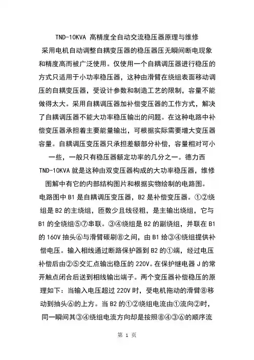
TND-10KVA 高精度全自动交流稳压器原理与维修采用电机自动调整自耦变压器的稳压器压无瞬间断电现象和精度高而被广泛使用。
仅使用一个自耦调压器进行稳压的方式只适用于小功率稳压器,这种由滑臂在绕组表面移动调压的自耦变压器,受设计参数和制造工艺的限制,容量不能做得太大。
采用自耦调压器加补偿变压器的工作方式,解决了自耦调压器不能大功率稳压输出的问题。
在这种电路中补偿变压器承担着主要能量输出,可根据实际需要增大变压器容量。
自耦调压变压器只承担差额部分补偿,容量相对可小一些,一般只有稳压器额定功率的几分之一。
德力西TND-10KVA就是这种由双变压器构成的大功率稳压器,维修图解中有它的内部结构图片和根据实物绘制的电路图。
电路图中B1是自耦调压变压器,B2是补偿变压器。
①②绕组是B2的主绕组,匝数少且线径粗,是主输出绕组,它与B1的全绕组⑤⑦串联。
③④绕组是B2的副绕组,并联在B1的160V抽头⑥与滑臂碳刷⑧之间,由B1给③④绕组提供补偿电压。
输入相线通过断路保护器到B2的①端,经过电压补偿后由②⑤交汇点输出稳压的220V。
在保护继电器J的常开触点闭合后送到相线输出端子。
两个变压器补偿稳压的原理如下:当输入电压超过220V时,受电机拖动的滑臂⑧移动到抽头⑥的上方。
当B2的①②绕组电流由①流向②时,同一瞬间其③④绕组电流方向却是按照⑧④③⑥的顺序流向。
两个绕组的电流方向相反,③④绕组产生的反向电压通过铁芯耦合,对①②绕组电压产生抵消减小的作用,降低了①②绕组的输出电压。
当输入电压低于220V时,滑臂⑧移动到抽头⑥下方。
设定①②绕组的电流方向仍然是从①到②,但③④绕组的电流方向变成⑥③④⑧的流向,与①②绕组的电流方向一样。
这时两个电压将叠加,使输出电压升高。
当输入电压是220V时,滑臂⑧移动到抽头⑥的位置。
③④绕组两端电压成0V,不再有补偿作用。
调压变压器滑臂驱动电机安装在环形变压器的中间,电机的伺服由控制电路完成。
正泰稳压器功能介绍一:TND1/ TNS1(SVC)系列高精度全自动单、三相交流稳压电源TND1/ TNS1(SVC)系列高精度全自动单、三相交流稳压电源TND1/TNS1(SVC) 系列全自动交流稳压电源是由接触式调压器及自动控制电路组成。
对电压信号进行取样、放大再控制伺服电机带动转臂及电刷按所需方向转动,使输出电压调整到额定值而达到稳压目的。
性能指标完全符合JB/T 10089标准。
该稳压电源具有外型美观大方、体积小、重量轻、自身功耗低、各种保护功能齐全、稳定可靠、输出波形失真小的特点。
可广泛应用于工业生产、科学研究、医疗卫生、家用电器等电网电压波动大或电网电压季节变化大的地区,能给任意负载提供优质电源。
二:TNDZ(DBW)/TNSZ(SBW)系列补偿型柱式交流自动稳压器TNDZ(DBW)/TNSZ(SBW)系列补偿型柱式交流自动稳压器TNDZ(DBW)/TNSZ(SBW)系列补偿型柱式交流自动稳压器分为单相TNDZ(DBW型)、三相(SBW型)二种,与其它形式稳压器相比具有容量大、效率高、电压调节平稳,适用负载广泛,能承受瞬时超载,可长期连续工作,手控自控随意切换,设有过压、短路保护功能,使用安装方便,运行可靠等特点。
可广泛应用于工业、农业、交通、邮电、军事、铁路、科研文化等领域的大型机电设备、金属加工设备、生产流水线,建筑工程设备、电梯、医疗器械、微机机房、电脑控制设备、刺绣轻纺设备、空调、广播电视、宾馆及家用电器照明等需要稳压的场所。
三:TND2系列高精度全自动交流稳压电源TND2系列高精度全自动交流稳压电源TND2系列高精度全自动交流稳压电源是本公司自行研制的第二代产品,由接触式调压器,自动控制电路进行取样、放大、控制伺服电机带动转臂、电刷按所需方向转动,使输出电压调整到额定值而达到稳压目的。
该稳压电源面板以LED中文显示,具有延时输出、过压、欠压保护,以及负载模拟量显示及过载报警;外型美观大方、体积小且厚度薄、重量轻、自身功耗低、稳定可靠、输出波形失真小的特点。
作为中国改革开放第一代优秀民营企业,德力西集团历经近四十载的不懈奋斗,在广大客户和合作伙伴的长期信赖与支持下,于2007年与全球500强施耐德电气强强携手,合资成立德力西电气有限公司(简称“德力西电气”)。
德力西电气业务覆盖配电电气、工业控制自动化、家居电气三大领域,致力于以高性价比、高效率和高质量的产品与服务,为全球新兴市场客户创造舒适、美观、安全、智能的居家用电环境和专业、安全、可靠、高效的工业自动化用电环境,探索中国低压电气行业企业发展新模式。
我们以客户和合作伙伴的利益为出发点,坚持以技术创新、质量保障、五星服务、品牌驱动为经营理念,打造电气全产业链新生态。
我们拥有700多家一级代理商、60000多家线下门店、多个线上销售平台和合作伙伴、5个研发中心、3个国家级实验室、3大自动化工业生产基地、五星级客户支持服务团队、17个国内物流中心以及数十个运输合作伙伴、1个国际物流中心和在发展中国家的4大业务合作伙伴,以及持续一致的全方位品牌建设及宣传,致力在全球范围内创造最佳客户体验闭环。
我们秉承“客户第一、合作、敏捷、创新、超越”的价值观,全心全意服务于我们的客户,同时携手合作伙伴建立具有统一价值观的社会责任生态圈,通过“德基金”全情回馈社会,用实际行动践行企业社会责任,持续打造具有德力西电气特色的“一老一小传统文化”的企业公益品牌,构建一个有温度的国际化低压电气领军企业 。
产品特征TND-系列 是运用美学思维设计的一款高精度全自动交流稳压器;产品整体结合立体感大R 角、圆形渐变通风孔、便捷一体化接线端子和LED 科技蓝光的完美结合设计出新一代“交流稳压器”,与传统产品相比,其外形简洁、造型新颖,安装使用方便,品质更加优良,是用电设备保驾护航的首选稳压电源产品!产品稳压精度高、损耗小,范围宽、无波形失真、具有过压、过载等保护功能。
适用范围广泛用于电压低、波动频繁的地区使用,可为家庭、工矿企业、机关、科研单位、实验室的精密仪器供电,是一种理想的交流稳压电源。
精密净化交流稳压电源说明书一、产品简介精密净化交流稳压电源是专门为稳定电压的滤除电网杂波对精密仪器设备造成损害而设计专用前置设备。
精密净化交流稳压电源以稳压电源宽、净化杂波能力强而著称,且有稳压精度高,输出稳定的特点,用于配置于航空、医院、教育等系统高级设备的前端,如:计算机、CT机、核磁共振机,通讯基站等,能有效保护了尖端设备的正常运行和使用寿命,在全世界各行各业,可以说精密的终端设备都不能缺少它的保护。
二、工作原理“1791(JJW)”系列精密净化交流稳压电源采用了国际上属于电源调节器技术尖端的正弦能量分配器程式(即属于“正弦能量分配器”)。
它采用双向可控硅对输出电压进行快速精确的调节,实现交流电压的稳定;再通过大功率LC滤波器对双向可控硅的输出电压进行波形校正,以保证良好的正弦波输出。
大功率LC滤波器同时又能吸收掉来自电网的各种噪声电压和尖峰干扰,此款“1791(JJW)”系列精密净化交流稳压电源同时也具备有稳定电压和抗干扰的双重功能。
三、技术指标“1791(JJW)”系列净化交流稳压电源除具有以上特点外还具有以下特点:1.高精确过压、欠压保护2.集成电路性能可靠3.多功能缺相保护4.防雷装置(如装备)5.市电稳压可手动切换(如装备)大型医疗设备专用型净化交流稳压电源可根据设备要求装备所有可应用功能。
注意:●“KV A”为额定功率“KW”为有效功率,例如额定功率为1KV A稳压电源,有效功率为0.8KW左右。
●如果您对所适用产品上标志(识)有不理解请来电询问阳环公司工程师,以避免因使用不当给您造成损失。
●因接错连线或使用不当造成的损失不在保修范围内。
四、安装1、开启包装箱后请先检查外壳、电压表(电流表)、开关、指示灯、数字显示屏(如装备)连线端子(如装备)等有无损坏,无损坏才能使用。
2、按照选用的稳压电源功率配合合适的软导线作为连接导线,并按稳压电源后面的标识连接。
3、某些功率小的机型已装备了从稳压电源到电源的连线,但您仍需要提供由负载到本机的连接线。
宽压精密稳压电源使用说明书(内附保修卡)扬州华翔电子有限公司1) 2) 3) 4) 5)稳压器概述及主要技术指标如何选购稳压器的使用功率稳压器实地安装及使用说明稳压器常见故障及排除方法常用规格输出电流表及附解警告用户欢迎您选用本公司生产的高精度宽压精密稳压电源,使用前请详细阅读本说明书,在对本产品性能充分了解的情况下正确使用,并妥善保管本说明书,以供后参考。
谢谢合作。
、概述及主要技术指标(一)、概述随着我国工业的发展,人民生活水平不断提高,用电设备设施不断增加,电力供应不能及时满足高速增长用电的需要,特别是夏季用电高峰,电压波动极为频繁,致使工矿企业用电设施和家庭用电电器长期处于欠压状态运行,严重影响电器的安全和使用寿命。
本产品稳压精度高、调整时间快、损耗小、可长时间工作、允许1.6倍额定容量的瞬间过载。
并具有过电压、欠电压、过电流保护,安全可靠。
适用家庭、工矿企业、机关、科研单位、实验室的精密仪器供电,是一种理想的交流稳压电源。
JWP、TND、DBW系列单相宽压精密稳压电源和SJW、SBW 系列三相宽压精密稳压电源是由接触式调压器、取样控制电路、伺服电机等主要部件组成。
当市电电压不稳定或用户负载变化引起电压波动时,取样电路将电压变化信号经处理送伺服电机,使其带动接触式调压器碳刷相应移动,来保证输出电压稳定。
、、主要技术指标1、系列型号含义JWP 单相、三相宽压精密稳压电源TSD 豪华型壁挂式高精度宽压精密稳压电源DBW单相、SBW三相大功率补偿式自动交流稳压器(二)导购参考如何选购稳压器的使用功率:1、稳压器所标输出功率是最大功率。
家用电器的标称功率是指有功功率,而冰箱、空调、水泵等感性负载在启动瞬时间电流很大,因此电冰箱、空调、水泵按功率x(3~5倍)。
例如:3匹美的空调(220V用电)1 匹等于0.75 千瓦*3匹=2.25 千瓦*3 倍感性负载启动电流=6.75千瓦以上稳压器适用。
(美的维修安装技师推荐选用8KVA 稳压器)2、以专业水电安装技师及工厂专业电工、工程师和稳压器使用功率算法:一般工业设备按额定功率至少乘以2 倍以上使用功率,当使用在具备电机运转设备、大电流启动装置及冲击性负载设备上时,应选择3倍以上容量的稳压器,以免启动电流过大,供电线路降压而无法正常工作。

□ 环境温度:-5~+40℃;□ 相对湿度:不大于90%(温度+25℃);□ 安装地点的海拔高度不超过2000m ;□ 工作环境:无化学性沉积、污垢、有害侵蚀性介质及易燃、易爆气体的室内。
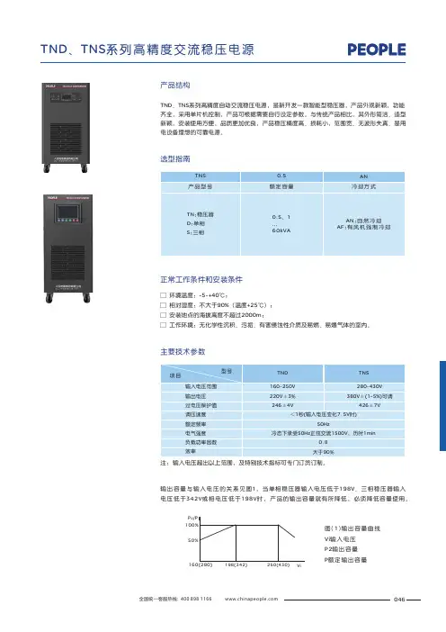
正常工作条件和安装条件选型指南TNSTN 稳压器D :单相S :三相:产品型号ANAN :自然冷却AF :有风机强制冷却冷却方式0.5额定容量0.5、1...60kVA TND 、TNS 系列高精度自动交流稳压电源,是新开发一款智能型稳压器,产品外观新颖,功能齐全,采用单片机控制,产品可根据需要自行设定参数。
与传统产品相比,其外形简洁、造型新颖,安装使用方便,品质更加优良,产品稳压精度高、损耗小,范围宽、无波形失真、是用电设备理想的可靠电源。
产品结构046主要技术参数TND TNS 型号 项目 输入电压范围输出电压过电压保护值调压速度额定频率电气强度负载功率因数效率160~250V 220V ±3%246±4V 280~430V 380V ±可调426±7V (1~5%)<1秒(输入电压变化7.5V 时)50Hz冷态下承受50Hz 正弦交流1500V ,历时1min 0.8大于90%注:输入电压超出以上范围,及特别技术指标可专门订货订制。
输出容量与输入电压的关系见图1,当单相稳压器输入电压低于198V 、三相稳压器输入电压低于342V 或相电压低于198V 时,产品的输出容量就有所降低,必须降低容量使用。
100%50%160(280)198(342)250(430)ViP /P2图输出容量曲线Vi 输入电压P2输出容量P 额定输出容量 (1)047A X ax图原理图2 TND-0.5~1.5kVA AX ax图 TND 2~5kVA 原理图3-220Vax A X 图4 TND 7~10kVA 原理图-ax A X图5 TND 15、20、30kVA 原理图-048输入ab cn输出ab cn输出输入ab cn输出输入图6 TND 1.5、3、4.5kVA 原理图-图7 TNS -6、9、15kVA 原理图图8 TNS -50、60kVA 原理图TND、TNS系列高精度交流稳压电源外形及安装尺寸图9 TND-0.5~10kVA台式产品外形图11 TNS-1.5~4.5kVA产品外形049图12 TNS-6~30kVA产品外形图13 TNS-50~60kVA产品外形050。
TSD 伺服式交流伺服式交流单相单相单相稳压器
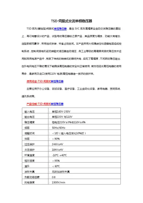
稳压器TSD 系列(壁挂型)伺服式单相稳压器,是在SVC 系列高精度全自动交流稳压器的基础上,再行完善设计的产品,该型号的稳压器较之原产品,其品质更为精良,功能大有增加,选型新颖而豪华,采用挂式安装,节省占地空间。
本产品采用大规模线性和逻辑电路组成控制系统,控制伺服电机驱动接触式调压器自动调压,将工业等级的高精度伺服式稳压技术运用到民用电源产品中,克服了传统的转接式的瞬间失电,实现了高精度,不间断的稳压输出,在外电网电压不稳的情况下能确保高档电器的安全和正常使用,有效地延长高档电器的使用寿命,是家用及进口(使用110V 电源)高档电器唯一良好的保护神。
使用场合-TSD 伺服式单相稳压器
主要应用于办公设备、测试设备、医疗设备、工业自动化设备、家用电器、照明系统、通讯系统等。
产品性能-TSD 伺服式单相稳压器输入电压
:单相160V-250V 输出电压
:单相220V 与110V 稳压精度
:相电压220V±3%与110V±6%频率
:50Hz/60Hz 调整时间
:<1秒(输入电压变化10%时)效率
:>90%过压保护
:246V±4V 欠压保护
:184V±4V 环境温度
:-10℃-+40℃相对湿度
:<95%温升
:<60℃波形失真
:无附加波形失真负载功率因素
:0.8抗电强度:1500V/min
绝缘电阻:>5MΩ
延时时间:长5分±2分,短5秒±2秒。
产品概述(TND高精度全自动交流稳压器) 上海鸿之电气---中国著名品牌TND系列高精度全自动交流稳压器是SVC系列交流稳压器的革新型产品之一。
本稳压器秉承了SVC优良性质,本稳压器更具有外形精美,感观豪华,经济完美等特点。
主要技术参数(TND、TNS高精度全自动交流稳压器)输入电压单相160V-250V三相277-430V<三相四线>过压保护246V±4V输出电压单相220V与110V三相线电压380V 相电压220V环境温度-10℃-+40℃稳压精度相电压220V±3%与110V±6%相对湿度<95%频率50Hz/60Hz 温升<60℃调整时间<1秒(输入电压变化10%时)波形失真无附加波形失真效率>90% 负载功率因素0.8抗电强度1500V/min绝缘电阻>5MΩ型号规格(TND、TNS高精度全自动交流稳压器)相数型号规格(kVA)产品尺寸(深×宽×高)(mm)包装尺寸(深×宽×高)(mm)台装相数型号规格(kVA)产品尺寸深×宽×高(mm)包装尺寸(深×宽×高)(mm)台装单相TND-0.5220×120×150340×290×4104单相TND-60790×430×1290900×650×14001TND-1240×140×170380×310×4504TND-80790×430×1290900×650×14001TND-1.5240×140×170380×310×4504三相TNS-1.5400×360×170520×480×281TND-2260×180×200320×230×2601TNS-3420×380×190540×500×311 TND-3320×190×230370×230×3001TNS-4.5420×380×190540×500×311TN D-5 380×220×300450×300×3701TNS-6370×280×690480×400×781TN D-7 380×220×330450×300×3701TNS-9350×330×780480×450×901TN D-8 400×240×330480×320×4101TNS-15400×370×710520×480×801TN D-1 0 400×240×330680×320×4101TNS-20460×430×790600×550×891TN D-1 5 400×330×650480×450×9001TNS-30460×430×790600×550×891TN D-2 0 400×330×650480×450×9001TNS-45650×430×950780×550×11001TN D-3 0 580×350×680680×480×9001TNS-60650×430×950780×550×11001TN D-4 5 530×430×1020640×530×11201 ---- ----- ---- ---上海鸿之电气---中国著名品牌。
无触点交流稳压器
NCR-
客服热线:(86-0577)62725681
NCR-2000VA NCR-3000VA NCR-5000VA
■产品特征■适用范围
■产品特点
NCR-系列 是一款无触点型交流稳压器,它集众多交流稳压器的优点于一体,通过软硬件结合控制,主电路的多重保护,解决了干扰和可控硅的共态导通问题,实现了彻底解决了有触点稳压器的机械磨损、噪声,响应慢等缺点。
广泛用于电压低、波动频繁的地区使用, 产品稳压精准,响应速度快,范围宽,多功能LED显示,无机械和触点磨损,可靠性强;并设有输出过压、过载,温度保护等。
执行标准:Q/DLX 355-2017
速稳压、多重智能保护和无触点稳压,器、电脑数据中心、通信、广播电视等设备等稳压。
■符合标准
频 率 Hz 50/60■ 外形尺寸及重量
规格型号
结构
单相台式外形尺寸(mm )
W ×L ×H 重量(kg )NCR-1000VA NCR-1500VA
NCR-2000VA NCR-3000VA NCR-5000VA
165
×
275×215165×275×215175×300×230215×305×265220×325×285
5.8
6.2
7.812.515.7
■ 产品规格外形尺寸示意图
外形尺寸重量参数NC R -无触点交流稳压器
系列 备注:例如1:NCR -1000VA,开单代码为NCR1;例如2:NCR -1.5kVA,开单代码为NCR1P5;。
JJW 、JSW 精密净化交流稳压器产品概述精密净化交流稳压电源,它集净化稳压和滤波、抗干扰等多种功能于一体,具有稳压范围宽、响应速度快、稳压精度高等优点,并能有效地抑制各种噪声和尖峰干扰,是目前交流稳压电源产品中的优选机种,是614系列电子交流稳压电源磁饱和稳压电源以及补偿式稳压电源的理想换代产品。
人民集团系列精密净化交流稳压电源,以其优越的性能,满足了不同场合电器设施的需要,它主 要应用于以下几个领域:科研部门、大专院校、工矿企业、医疗卫生、广播台站、通讯、交通运输 、政府事业等各行各业,大量使用于微机及其周边装置、微机网络,各种医疗电子仪器设备、通讯 广播设备、交通信号系统、测试检验设备、各种数控机床、自动插件机等自动化生产设备。
产品符合: SJ /T 10541 标准。
选型指南□ 30kVA ;□ 三相:3kVA ;6kVA ;10kVA ;15kVA ;20kVA ;30kVA ;50kVA ;60kVA ;100kVA ;单相:1kVA ;2kVA ;3kVA ;5kVA ;10kVA ;15kVA ;20kVA ;规格表1主要技术数据037本稳压电源是以正弦能量分配器为核心,配以大容量滤波器和集成化控制电路而构成,主回路的工作原理大致如下图1和图2:净化电源电路原理图(此图仅供参考,如有修改,恕不另行通知)输入输出图1LNLNKC1BJL2L3L5C5C3L1FUSESCRZ C2R8IC3IC2C1R6R3VR1R1R2R5R7C3R11C9R15IC4+12V VINGNDR13C5C6C7C8B2L1C -1L3C -3R24B1L5C -2XOUTIN图2T1R10D1D2N9C4D7JXTST2T3R22R21WDR23R18D4D5T4图中K 为控制开关,控制着整个稳压电源的起停,C1-C3及L1-L3和可变阻抗“Z ”构成了有名的正弦能量分配电路。
L3或L2组成一自藕变压器T1,可变阻抗“Z ”由双向可控硅SCR 和电感L 组成,外加三次谐波滤波器L3、C3和五次谐波滤波器L5、C5。
1适用范围TND1/TNS1(SVC) 系列全自动交流稳压电源是由接触式调压器及自动控制电路组成。
对电压信号进行取样、放大再控制伺服电机带动转臂及电刷按所需方向转动,使输出电压调整到额定值而达到稳压目的。
性能指标完全符合JB/T 10089标准。
该稳压电源具有外型美观大方、体积小、重量轻、自身功耗低、各种保护功能齐全、稳定可靠、输出波形失真小的特点。
可广泛应用于工业生产、科学研究、医疗卫生、家用电器等电网电压波动大或电网电压季节变化大的地区,能给任意负载提供优质电源。
2型号及含义TN□□(SVC)-□/□稳压电源容量(kVA)国外型号设计序号相数:D为单相,S为三相自动调压器(稳压电源)冷却方式:AN表示空气为自然对流的冷却方式,产品上未注默认为此类型; AF表示用风扇抽出内部热空气或直接吹冷产品的冷却方式。
3正常工作条件和安装条件3.1 环境温度:-5℃+45℃。
3.2 相对湿度:不大于90%(温度为+25℃)。
3.3 安装地点的海拔高度不超过1000m。
3.4 工作环境:无化学性沉积、污垢、有害侵蚀性介质及易燃、易爆气体的室内。
~4主要参数及技术性能相数输入电压输出电压频率调整时间单相 160V 250V ~220V±4%(10kVA及以上)50Hz 三相280V 430V(三相四线制)~相电压220V±4%,线电压380V±4%(三相四线制)50Hz≤(3~6)s(当输入电压变化20V时) ≤(3~6)s(当输入相电压变化20V时) 规格(按容量分)5kVA、10kVA、15kVA、20kVA、30kVA 0.5kVA、1kVA、1.5kVA、2kVA、3kVA 1.5kVA、3kVA、4.5kVA、6kVA、9kVA15kVA、20kVA、45kVA、60kVA220V±4%和110V±8%(5kVA及以下)输出欠电压保护值(180±8)V (1.5kVA及以下及110V输出无保护)相电压(180±8)V(4.5kVA及以下欠压输出无保护)输出过电压保护值(246±4)V (1.5kVA及以下及110V输出无保护)相电压(246±4)V(4.5kVA及以下过压输出无保护)高精度全自动单、三相交流稳压电源TND1/TNS1(SVC)系列5产品特点产品的输出容量与输入电压值存在密切联系,输出容量曲线详见图1。