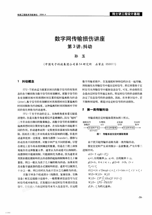
ITUT G.823 (原文) 同步数字传输网络中的抖动和漂移
- 格式:pdf
- 大小:391.71 KB
- 文档页数:50
传输设备代维考试多选题[C].2010-01-19 14:011、关于抖动和漂移的描述中,正确的是()A.抖动和漂移与系统的定时特性有关;B.抖动指数字信号的特定时刻相对其理想时间位置的短时间偏离。
所谓短时间偏离是指变化频率高于10Hz的相位变化;C.漂移指数字信号的特定时刻相对其理想时间位置的长时间的偏离。
所谓长时间是指变化频率低于10Hz的相位变化;D.指针调整可以产生抖动,但2M信号映射过程不会产生抖动;ABC2、下列关于SDH常用保护组网说法,正确的是()A.PP环的双发功能是在交叉板上实现的,选收功能是在支路板上实现的;B.配置了SNCP属性的逻辑系统,PDH支路业务的保护方式与PP环相同,所以必须配置支路通道属性为“p”;C.双向复用段保护倒换和业务无关,其保护通道是共享的,双向复用段的容量一般比通道保护环高;D.2500+组成的一个四纤双向复用段保护环比两个二纤双向复用段保护环容量高;ABC3、下面关于指针调整的说法,正确的是()A.从2M信号适配成VC12直至合成STM-1整个过程,可能产生TU指针调整;B.支路板检测到的TU指针调整都是AU指针调整转化过来的;C.2500+光板上报AU指针调整是因为上游网元发送信号的AU指针发生了改变;D.在时钟不同步的情况下,VC12业务,点对点组网不会上报AU指针调整;BCD4、下面关于光板灵敏度和过载点的说法,正确的是()A.开局中,要求光板处测量到的“实际接收光功率”大于该光板的灵敏度指标值3dB,小于该光板的过载光功率指标值5dB;B.光板接收灵敏度是在一定误码率情况下测得的,接收光功率在灵敏度附近,设备长期运行可能产生误码;C.光接收灵敏度只和光板的收光模块有关,和光板的发光模块无关;D.国标规定,S4.1光接口的过载点是0dBm;ABC5、OSN3500/2500/1500内部Lanswitch通信及485总线之间关系说法正确的是()A.485总线相互无保护,485总线和以太网通信之间也无保护;B.两条485总线相互保护,即当一条485总线故障时,其上承载信息由另外一条485总线转发;C.以太网和两条485总线之间相互保护,即任意一路通信故障,都会通过另外两路进行转发;D.485总线和以太网总线之间保护是单向的,即当两条485总线都故障时,其上信息可以通过以太网转发。

INTERNATIONAL TELECOMMUNICATION UNIONG.823(03/2000) TELECOMMUNICATIONSTANDARDIZATION SECTOROF ITUSERIES G: TRANSMISSION SYSTEMS AND MEDIA, DIGITAL SYSTEMS AND NETWORKSDigital networks – Quality and availability targetsThe control of jitter and wander within digital networks which are based on the 2048 kbit/s hierarchyITU-T Recommendation G.823(Formerly CCITT Recommendation)ITU-T G-SERIES RECOMMENDATIONSTRANSMISSION SYSTEMS AND MEDIA, DIGITAL SYSTEMS AND NETWORKS INTERNATIONAL TELEPHONE CONNECTIONS AND CIRCUITS G.100–G.199G.200–G.299 GENERAL CHARACTERISTICS COMMON TO ALL ANALOGUE CARRIER-TRANSMISSION SYSTEMSINDIVIDUAL CHARACTERISTICS OF INTERNATIONAL CARRIER TELEPHONEG.300–G.399 SYSTEMS ON METALLIC LINESG.400–G.449 GENERAL CHARACTERISTICS OF INTERNATIONAL CARRIER TELEPHONESYSTEMS ON RADIO-RELAY OR SATELLITE LINKS AND INTERCONNECTION WITHMETALLIC LINESCOORDINATION OF RADIOTELEPHONY AND LINE TELEPHONY G.450–G.499 DIGITAL NETWORKS G.800–G.899 General aspects G.800–G.809 Design objectives for digital networks G.810–G.819 Quality and availability targets G.820–G.829 Network capabilities and functions G.830–G.839 SDH network characteristics G.840–G.849 Management of transport network G.850–G.859 SDH radio and satellite systems integration G.860–G.869 Optical transport networks G.870–G.879 DIGITAL SECTIONS AND DIGITAL LINE SYSTEM G.900–G.999For further details, please refer to the list of ITU-T Recommendations.ITU-T Recommendation G.823The control of jitter and wander within digital networkswhich are based on the 2048 kbit/s hierarchySummaryThis ITU-T Recommendation specifies the maximum network limits of jitter and wander that shall not be exceeded and the minimum equipment tolerance to jitter and wander that shall be provided at any relevant transport or synchronization interfaces which are based on the 2048 kbit/s hierarchy. The requirements for the jitter and wander characteristics that are specified in this ITU-T Recommendation must be adhered to in order to ensure interoperability of equipment produced by different manufacturers and a satisfactory network performance.SourceITU-T Recommendation G.823 was revised by ITU-T Study Group 13 (1997-2000) and approved under the WTSC Resolution 1 procedure on 10 March 2000.KeywordsClocks, Input Jitter Tolerance, Input Wander Tolerance, Network Limits, Output Jitter, Output Wander, Synchronization, Timing.ITU-T G.823 (03/2000) iFOREWORDThe International Telecommunication Union (ITU) is the United Nations specialized agency in the field of telecommunications. The ITU Telecommunication Standardization Sector (ITU-T) is a permanent organ of ITU. ITU-T is responsible for studying technical, operating and tariff questions and issuing Recommendations on them with a view to standardizing telecommunications on a worldwide basis.The World Telecommunication Standardization Conference (WTSC), which meets every four years, establishes the topics for study by the ITU-T study groups which, in turn, produce Recommendations on these topics.The approval of ITU-T Recommendations is covered by the procedure laid down in WTSC Resolution 1.In some areas of information technology which fall within ITU-T’s purview, the necessary standards are prepared on a collaborative basis with ISO and IEC.NOTEIn this Recommendation, the expression "Administration" is used for conciseness to indicate both a telecommunication administration and a recognized operating agency.INTELLECTUAL PROPERTY RIGHTSITU draws attention to the possibility that the practice or implementation of this Recommendation may involve the use of a claimed Intellectual Property Right. ITU takes no position concerning the evidence, validity or applicability of claimed Intellectual Property Rights, whether asserted by ITU members or others outside of the Recommendation development process.As of the date of approval of this Recommendation, ITU had not received notice of intellectual property, protected by patents, which may be required to implement this Recommendation. However, implementors are cautioned that this may not represent the latest information and are therefore strongly urged to consult the TSB patent database.ã ITU 2001All rights reserved. No part of this publication may be reproduced or utilized in any form or by any means, electronic or mechanical, including photocopying and microfilm, without permission in writing from the ITU. ii ITU-T G.823 (03/2000)CONTENTSPage1 Scope (1)2 References (2)3 Definitions (2)4 Abbreviations (3)5 Network limits for traffic interfaces (4)5.1 Network limits for output jitter at traffic interfaces (4)5.2 Network limits for output wander at traffic interfaces (5)5.2.1 2048 kbit/s interface output wander limit (6)5.2.2 34 368 kbit/s interface output wander limit (7)5.2.3 139 264 kbit/s interface output wander limit (8)6 Network limits for synchronization interfaces (8)6.1 Network limits for output jitter at synchronization interfaces (9)6.2 Network limits for output wander at synchronization interfaces (9)6.2.1 PRC interface output wander limit (10)6.2.2 SSU interface output wander limit (11)6.2.3 SEC interface output wander limit (13)6.2.4 PDH synchronization interface output wander limit (14)7 Jitter and wander tolerance of network interfaces (16)7.1 Jitter and wander tolerance of traffic interfaces (16)7.1.1 64 kbit/s input jitter and wander tolerance (17)7.1.2 2048 kbit/s input jitter and wander tolerance (18)7.1.3 8448 kbit/s input jitter and wander tolerance (19)7.1.4 34 368 kbit/s input jitter and wander tolerance (20)7.1.5 139 264 kbit/s input jitter and wander tolerance (21)7.2 Jitter and wander tolerance of synchronization interfaces (22)Annex A − Network model underlying the synchronization network limit (22)A.1 Introduction (22)A.2 Considerations on the network model (22)A.3 Information regarding the simulations (25)Annex B − Network wander reference model and parameters (26)B.1 Wander reference model for traffic interfaces (26)B.1.1 Asynchronous PDH connection (26)B.1.2 Synchronous PDH connection (27)B.1.3 Specification of wander by MRTIE parameter (27)ITU-T G.823 (03/2000) iiiPage B.2 Wander reference model for synchronization interfaces (28)B.2.1 Specification of wander by MTIE and TDEV parameters (30)Appendix I − Wander limit considerations for SDH transport networks (30)I.1 Introduction (30)I.1.1 Wander reference model for SDH (30)I.1.2 Sources of wander (31)I.1.3 Wander accumulation limiting effects (32)I.1.4 Network configuration and performance (32)I.1.5 Correlation of wander sources (32)I.1.6 Network conditions for the output wander limits (32)I.2 Derivation of wander specification limits (33)I.2.1 Wander specification limits (34)Appendix II − Measurement methodologies for output wander (34)interfaces (34)II.1 SynchronizationII.1.1 Synchronous signals (34)interfaces (35)II.2 TrafficII.2.1 Synchronous signals (PDH bit-rates) (35)II.2.2 Asynchronous signals (PDH bit-rates) (36)Appendix III − Measurement guidelines for input jitter and wander tolerance of equipment interfaces (38)iv ITU-T G.823 (03/2000)Introduction and backgroundIn a digital network, jitter and wander accumulate on transmission paths according to the jitter and wander generation and transfer characteristics of each equipment interconnected. This equipment may be different types of multiplexers/demultiplexers, cross-connects, clocks and line systems, for example.An excessive amount of jitter and wander can adversely affect both digital (e.g. by generation of bit errors, slips and other abnormalities) and analogue signals (e.g. by unwanted phase modulation of the transmitted signal). The consequences of such impairment will, in general, depend on the particular service that is being carried and the terminating or adaptation equipment involved.It is therefore necessary to set limits on the maximum magnitude of jitter and wander, and the corresponding minimum jitter and wander tolerance at network interfaces, in order to guarantee a proper quality of the transmitted signals and a proper design of the equipment. These network limits are independent of the particular service that is being carried.ITU-T G.823 (03/2000) vITU-T Recommendation G.823The control of jitter and wander within digital networkswhich are based on the 2048 kbit/s hierarchy1 ScopeThis ITU-T Recommendation specifies the relevant parameters and their limiting values that are able to satisfactorily control the amount of jitter and wander present at Network Node Interfaces (NNI) of Plesiochronous Digital Hierarchy (PDH) and synchronization networks which are based on the first-level hierarchical bit rate of 2048 kbit/s.This ITU-T Recommendation also specifies the jitter and wander requirements at PDH User-Network Interfaces (UNI). However, particular terminals or services may have additional jitter and wander requirements and in those cases the relevant ITU-T Recommendations shall apply. Requirements for NNI of PDH and synchronization networks which are based on the first-level hierarchical bit rate of 1544 kbit/s are specified in ITU-T Recommendation G.824 and requirements for Synchronous Digital Hierarchy (SDH) NNI are specified in ITU-T Recommendation G.825.The jitter and wander requirements specified in this ITU-T Recommendation are applicable to the interfaces irrespective of the underlying transport mechanism (PDH, SDH or ATM networks, for example).The jitter and wander requirements for an interface will be different, depending on whether the signal at the interface is used to transport traffic and/or synchronization. The requirements for both traffic and synchronization interfaces are specified in this ITU-T Recommendation in the appropriate clauses.A synchronization network that conforms to the network limits for jitter and wander specified in this ITU-T Recommendation will be suitable for the synchronization of SDH and Public Switched Telephone Network (PSTN) networks.This ITU-T Recommendation also specifies the jitter and wander requirements for interfaces using the generic frame structures at PDH rates as defined in ITU-T Recommendation G.832.The electrical characteristics of the relevant PDH network interfaces are defined in ITU-T Recommendation G.703.The jitter and wander control philosophy of this ITU-T Recommendation is based on the need:a) to specify a maximum network limit of jitter and wander that shall not be exceeded at anyrelevant interface;b) to specify a minimum equipment tolerance to jitter and wander that shall be provided at anyrelevant interface;c) to establish a consistent framework for the specification of individual digital equipmenttypes; andd) to provide sufficient information and guidelines for organizations to measure and study jitterand wander characteristics in any network configuration.ITU-T G.823 (03/2000) 12 ReferencesThe following ITU-T Recommendations and other references contain provisions which, through reference in this text, constitute provisions of this Recommendation. At the time of publication, the editions indicated were valid. All Recommendations and other references are subject to revision; all users of this Recommendation are therefore encouraged to investigate the possibility of applying the most recent edition of the Recommendations and other references listed below. A list of the currently valid ITU-T Recommendations is regularly published.– ITU-T Recommendation G.703 (1998), Physical/electrical characteristics of hierarchical digital interfaces.– ITU-T Recommendation G.707 (1996), Network node interface for the Synchronous Digital Hierarchy (SDH).– ITU-T Recommendation G.783 (1997), Characteristics of Synchronous Digital Hierarchy (SDH) equipment functional blocks.– ITU-T Recommendation G.803 (2000), Architecture of transport networks based on the Synchronous Digital Hierarchy (SDH).– ITU-T Recommendation G.810 (1996), Definitions and terminology for synchronization networks.– ITU-T Recommendation G.811 (1997), Timing characteristics of primary reference clocks. – ITU-T Recommendation G.812 (1998), Timing requirements of slave clocks suitable for use as node clocks in synchronization networks.– ITU-T Recommendation G.813 (1996), Timing characteristics of SDH equipment slave clocks (SEC).– CCITT Recommendation G.822 (1988), Controlled slip rate objectives on an international digital connection.– ITU-T Recommendation G.824 (2000), The control of jitter and wander within digital networks which are based on the 1544 kbit/s hierarchy.– ITU-T Recommendation G.825 (2000), The control of jitter and wander within digital networks which are based on the Synchronous Digital Hierarchy (SDH).– ITU-T Recommendation G.832 (1998), Transport of SDH elements on PDH networks – Frame and multiplexing structures.– ITU-T Recommendation O.150 (1996), General requirements for instrumentation for performance measurements on digital transmission equipment.– ITU-T Recommendation O.171 (1997), Timing jitter and wander measuring equipment for digital systems which are based on the Plesiochronous Digital Hierarchy (PDH).– ITU-T Recommendation O.172 (1999), Jitter and wander measuring equipment for digital systems which are based on the Synchronous Digital Hierarchy (SDH).3 DefinitionsThis ITU-T Recommendation defines the following terms. Additional definitions relating to synchronization networks are provided in ITU-T Recommendation G.810, whilst the architectural principles of synchronization networks are described in ITU-T Recommendation G.803. Information regarding the wander reference models used in this ITU-T Recommendation is provided in Annexes A and B.2ITU-T G.823 (03/2000)interface: These interfaces provide an output signal with frequency that is 3.1 synchronousnormally traceable to a PRC.interface: These interfaces provide an output signal with frequency that is 3.2 asynchronousnot traceable to a PRC and that meets the frequency offset requirements given in ITU-T Recommendation G.703.interface: These interfaces may be asynchronous or synchronous and network jitter 3.3 trafficand wander limits are specified using the Maximum Relative Time Interval Error (MRTIE) parameter in this ITU-T Recommendation. Input jitter and wander tolerance is also specified in this ITU-T Recommendation. This interface category can be further sub-divided as follows:a) Interface is not able to provide synchronization, and is not required to. An example is aninterface supporting only 34 368 or 139 264 kbit/s PDH signals according to ITU-T Recommendation G.703.b) Interface is not able to provide synchronization at the defined performance level, butnevertheless is used to provide timing to other network elements such as terminal equipment, remote concentrators, etc. Examples include 2048, 34 368 and 139 264 kbit/s PDH signals transported on SDH, which may be subject to pointer justifications. ITU-T Recommendation G.803 recommends that these interfaces are not to be used for synchronization.c) Interface is able to provide synchronization at the defined performance level, in which caseit is defined to be a synchronization interface. An example is a synchronization interface operating at 2048 kbit/s. This sub-category may also include interfaces using the generic frame structures at PDH rates as defined in ITU-T Recommendation G.832.interface: These interfaces are synchronous and network wander limits are 3.4 synchronizationspecified using Maximum Time Interval Error (MTIE) and Time Deviation (TDEV) parameters with values given in this ITU-T Recommendation. The input jitter and wander tolerance of clock equipment ports is specified in other Recommendations (refer to 7.2).4 AbbreviationsThis ITU-T Recommendation uses the following abbreviations. Additional abbreviations relating to synchronization networks are provided in ITU-T Recommendation G.810.ATM Asynchronous Transfer ModeAU-n Administrative Unit, level nCLK ClockCMI Coded Mark InversionITU-T International Telecommunication Union – Telecommunication Standardization SectorFilterLPF Low-PassMRTIE Maximum Relative Time Interval ErrorMS-AIS Multiplex Section Alarm Indication SignalMTIE Maximum Time Interval ErrorElementNE NetworkNNI Network Node InterfacePDH Plesiochronous Digital Hierarchypk-pk peak-to-peakPLL Phase Locked Loopppm parts per millionPRBS Pseudo-Random Binary SequencePRC Primary Reference ClockPSTN Public Switched Telephone NetworkRMS Root Mean SquareRTIE Relative Time Interval ErrorSDH Synchronous Digital HierarchySEC SDH Equipment ClockSSU Synchronization Supply UnitSTM-N Synchronous Transport Module, level NTDEV Time DeviationTIE Time Interval ErrorTU-m Tributary Unit, level mIntervalUI UnitUIpp Unit Interval, peak-to-peakInterfaceUNI User-NetworkUTC Universal Time CoordinatedVC-n Virtual Container, level n5 Network limits for traffic interfaces5.1 Network limits for output jitter at traffic interfacesThe limits given in this clause represent the maximum permissible levels of jitter at interfaces within a digital network. Jitter as measured over a 60 second interval shall not exceed the limits specified in Table 1, when using the specified measurement filters.There is a close relationship between network limits and input tolerance such that the jitter measurement filter cut-off frequencies used in this clause have the same values as the jitter tolerance mask corner frequencies used in 7.1. Appendix I/G.825 has further information regarding this relationship.The limits given in Table 1 shall be met for all operating conditions and regardless of the amount of equipment preceding the interface. In general, these network limits are compatible with the minimum tolerance to jitter that all equipment input ports are required to provide.The functional description for measuring output jitter at a digital interface is provided in ITU-T Recommendation O.172.The high-pass measurement filters of Table 1 have a first-order characteristic and a roll-off of 20 dB/decade. The low-pass measurement filters have a maximally-flat, Butterworth characteristic and a roll-off of –60 dB/decade. Further specifications for the frequency response of the jitter measurement function such as measurement filter accuracy and additional allowed filter poles are given in ITU-T Recommendation O.172.Instrumentation in accordance with ITU-T Recommendations O.172 and O.171 is appropriate for measurement of jitter in SDH and PDH systems, respectively.NOTE − ITU-T Recommendation O.172 includes test set specifications for the measurement of SDH tributaries operating at PDH bit rates, where the test set requirements are more stringent than those relating only to PDH systems. Therefore, instrumentation in accordance with ITU-T Recommendation O.172 shall be used at PDH interfaces in SDH systems.Table 1/G.823 − Maximum permissible jitter at traffic interfacesInterfaceMeasurementbandwidth,–3 dB frequencies (Hz)Peak-to-peak amplitude(UIpp) (Note 3)64 kbit/s 20 to 20 k 0.25(Note 1) 3 k to 20 k 0.052048 kbit/s 20 to 100 k 1.518 k to 100 k (Note 2) 0.28448 kbit/s 20 to 400 k 1.53 k to 400 k (Note 2) 0.234 368 kbit/s 100 to 800 k 1.510 k to 800 k 0.15139 264 kbit/s 200 to 3.5 M 1.510 k to 3.5 M 0.075NOTE 1 − For the codirectional interface only.NOTE 2 − For 2048 kbit/s and 8448 kbit/s interfaces within the network ofan operator, the high-pass cut-off frequency may be specified to be 700 Hz(instead of 18 kHz) and 80 kHz (instead of 3 kHz) respectively. However, atinterfaces between different operator networks, the values in the table apply,unless involved parties agree otherwise.NOTE 3 –64 kbit/s 1 UI = 15.6 µs2048 kbit/s 1 UI = 488 ns8448 kbit/s 1 UI = 118 ns34 368 kbit/s 1 UI = 29.1 ns139 264 kbit/s 1 UI = 7.18 ns5.2 Network limits for output wander at traffic interfacesThe MRTIE specifications given in this subclause are intended for application to both asynchronous and synchronous PDH interfaces. Refer to Figures B.1 and B.2, respectively, for the reference network configurations. In the case of asynchronous interfaces, a frequency offset within the limits specified in ITU-T Recommendation G.703 is permitted, in addition to the wander specified in the following subclauses.It is required that, within a synchronized network, digital equipment provided at nodes shall accommodate permitted phase deviations on the incoming signal, i.e. under normal synchronized conditions, impairments will not occur.However, it should be recognized that, as a result of some performance degradations, failure conditions, maintenance actions and other events, the phase difference between the incoming signal and the internal timing signal of the terminating equipment may exceed the jitter and wander tolerance of the equipment which may result in an abnormal event such as a slip or bit-error burst.In addition, at a node which connects to an independently-synchronized network (or where plesiochronous operation is used in national networks), the phase difference between the incoming signal and the internal timing signal of the terminating equipment may eventually exceed the wander tolerance of the equipment in which case an abnormal event such as a slip may occur. The maximum permissible long-term mean controlled slip rate resulting from this mechanism is derived from the clock performance defined in ITU-T Recommendation G.811, i.e. no more than one slip in 70 days. NOTE − The wander specifications defined in the following subclauses are consistent with the derivation of network limits described for the case of SDH network transport in Appendix I.The wander measurement requirements (e.g. sampling time and measurement interval) for MTIE, MRTIE and TDEV parameters, the 10 Hz wander measurement filter characteristic and the functional description for measuring output wander are described in ITU-T Recommendation O.172. Instrumentation in accordance with ITU-T Recommendation O.172 is appropriate for measurement of wander parameters.Measurement methodologies used to measure the MRTIE parameter are described in Appendix II. 5.2.1 2048 kbit/s interface output wander limitThe maximum level of wander that may exist at a 2048 kbit/s network interface, expressed in MRTIE, shall not exceed the limit given in Table 2. The resultant overall specification is illustrated in Figure 1.Table 2/G.823 − 2048 kbit/s interface output wander limitObservation Intervalτ (sec) MRTIE requirement(µs)0.05 <τ≤ 0.2 46 τ0.2 <τ≤ 32 932 <τ≤ 64 0.28 τ64 <τ≤ 1 000 (Note) 18NOTE − For the asynchronous configuration (refer toFigure B.1), the maximum observation interval to be considered is 80 seconds.T1315370-99Observation Interval τ (sec)MRTIE (µsec)1001892.310.111010010000.050.2326410000.01Figure 1/G.823 − 2048 kbit/s interface output wander limit5.2.2 34 368 kbit/s interface output wander limitThe maximum level of wander that may exist at a 34 368 kbit/s network interface, expressed in MRTIE, shall not exceed the limit given in Table 3. The resultant overall specification is illustrated in Figure 2.NOTE − 34 368 kbit/s signals can be framed in accordance with ITU-T Recommendation G.832.Table 3/G.823 − 34 368 kbit/s interface output wander limitObservation Intervalτ (sec) MRTIE requirement(µs)0.05 < τ ≤ 0.073 14 τ 0.073 < τ ≤ 2.5 1 2.5 < τ ≤ 10 0.4 τ 10 < τ ≤ 804T1315380-99Observation Interval τ (sec)MRTIE (µsec)0.70.11101000.050.073 2.510800.0114Figure 2/G.823 − 34 368 kbit/s interface output wander limit5.2.3 139 264 kbit/s interface output wander limitThe maximum level of wander that may exist at a 139 264 kbit/s network interface, expressed in MRTIE, shall not exceed the limit given in Table 4. The resultant overall specification is illustrated in Figure 3.NOTE − 139 264 kbit/s signals can be framed in accordance with ITU-T Recommendation G.832.Table 4/G.823 − 139 264 kbit/s interface output wander limitObservation Intervalτ (sec) MRTIE requirement(µs)0.05 < τ ≤ 0.15 6.8 τ 0.15 < τ ≤ 2.5 1 2.5 < τ ≤ 10 0.4 τ 10 < τ ≤ 804T1315390-99Observation Interval τ (sec)MRTIE (µsec)1010.340.10.11101000.050.15 2.510800.0114Figure 3/G.823 − 139 264 kbit/s interface output wander limit6 Network limits for synchronization interfacesThe specification of network limits for synchronization interfaces is primarily intended to reflect the results of a theoretical analysis of the worst-case accumulation of jitter and wander in a synchronization network. These values then serve to specify tolerance requirements for synchronization equipment.It should, however, also be possible to verify through measurements in a real network that the jitter and wander at a particular interface does not exceed the specified limits. The location of the interface in the synchronization chain of that network determines what margin may be expected with reference to the network limits.As shown in Figure B.3, an SSU may receive its timing via SDH or PDH distribution. The network limit at the output of these distribution chains represents the amount of jitter and wander that an SSU may experience at its input. Since there is more jitter allowed at PDH interfaces than at SDH Synchronous Transport Module, level N (STM-N) interfaces, the network limit for the PDH distribution outputs represents the worst-case that the SSU should tolerate at its input.The jitter and wander tolerance of an SEC should be (at least) the amount of jitter and wander at the input of the last SEC of a synchronization chain. Since the contribution of the last SEC in the chain to the network limit at SEC outputs (that is the amount of jitter and wander that may be expected at the output of the last SEC of the chain) is small, the network limit at the SEC output interface can be used as the jitter and wander tolerance requirement for an SEC.6.1 Network limits for output jitter at synchronization interfacesThe maximum allowable high frequency noise components of a timing signal are specified by the network limits for jitter given in Table 5. These network limits are compatible with the minimum tolerance to jitter that clock equipment input ports are required to provide. The limits given in Table 5 shall be met for all operating conditions at 2048 kbit/s and 2048 kHz synchronization interfaces.Jitter as measured over a 60 second interval shall not exceed the specified limits, when using the specified measurement filters.The functional description for measuring output jitter at a digital interface is provided in ITU-T Recommendation O.172. Further requirements concerning the measurement of jitter are defined in 5.1.Table 5/G.823 − Maximum permissible jitter at synchronization interfacesOutput InterfaceMeasurementbandwidth,–3 dB frequencies (Hz)Peak-to-peak amplitude(UIpp)PRC 20 to 100 k 0.05SSU 20 to 100 k 0.05SEC 20 to 100 k 0.549 to 100 k 0.2PDH synchronization 20 to 100 k 1.518 k to 100 k 0.2NOTE − For 2048 kbit/s and 2048 kHz synchronization interfaces, UIpp refers tothe reciprocal of the clock frequency.6.2 Network limits for output wander at synchronization interfacesAt very low frequencies, synchronization networks are transparent to wander. Consequently, two signals received in the same node that derive their timing from the same source, but over different paths, may in the worst-case have opposite phase deviation. The minimum wander tolerance in the frequency range where relevant equipment is affected by the differential phase variation between two inputs is therefore higher than the network limit for absolute wander. The performance of a clock is only influenced by the phase variation that is experienced at the selected synchronization input. That is why the absolute network limits in the following subclauses can be used directly to specify wander tolerance of the SSU and SEC.The network limit requirements for TDEV are derived from simulation, taking into account the 18 µs wander budget and the requirements of ITU-T Recommendation G.822 (further information is provided in Annex A). However, large diurnal wander with a period of one day and sinusoidal characteristic may cause the TDEV network limit (at SSU, SEC or PDH interfaces) to be exceeded, even if the corresponding MTIE requirement is met. This is because the TDEV parameter does not strongly filter sinusoidal components of wander.。

附1-习题答案第一节概述1. SDH体制有完善的监控机制提高网络安全性,更重要的是,SDH的同步复用可直接从高速信号中插/分低速信号,避免了信号的层层复用/解复用,减少了信号的损伤。
第二节SDH信号的帧结构和复用步骤1. 8 ;2. 63 ;3. 1 。
第三节开销和指针1. MS-AIS、MS-RDI均有K2的b6-b8检测。
当b6-b8为111时,是MS-AIS;为110时,是MS-RDI。
2. 当收端找不到A1、A2字节(无法正确定帧),会出现ROOF告警;ROOF 告警持续一定的时间,设备进入帧丢失状态,产生R-LOF告警。
3. AU-LOP告警、AU-AIS告警。
4. B1、B2、B3、V5 。
第四节SDH设备的逻辑构成1. R--LOS或R-LOF是SK2b6-b8为111,产生MS-AIS;对端直接发来的信号中K2b6-b8本身为111,导致本端MS-AIS。
2. HP-UNEQ、HP-TIM、HP-SLM和对端发来的HP-RDI。
3. STM-N光信号——VC4电信号。
4. DXC4/1表示DXC输入信号的最高速率级别为140M/155M,最小交叉级别为VC12。
第五节SDH网络结构和网络保护机理1. TU-AIS。
2. R-LOS、R-LOF、MS-AIS、MS-EXC。
3. 2016。
第六节光接口类型和参数1. 加扰的NRZ码。
2. 表示光接口用于局内通信,信号速率155M,用G.652光纤。
第七节定时与同步1. 主从同步、伪同步。
2. 外时钟、线路时钟、支路时钟、设备内置时钟。
第八节传输性能1. 定时抖动(抖动)是指数字信号的特点时刻(例如最佳抽样时刻)相对其理想时间位置的短时间偏离。
所谓短时间偏离是指变化频率高于10Hz的相位变化。
而漂移指数字信号的特定时刻相对其理想时间位置的长时间的偏离,所谓长时间是指变化频率低于10Hz的相位变化。
附2-专用词汇及缩略语1. 为什么SDH体制适合大容量传输的情况?(1) 2M复用在VC4中的位置是第二个TUG3、第三个TUG2、第一个TU12,那么该2M的时隙序号为。
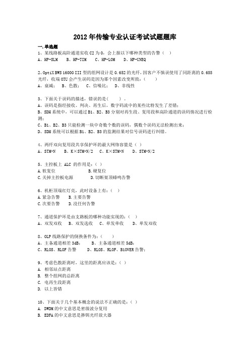
2012年传输专业认证考试试题题库一.单选题1、某线路板高阶通道实收C2为0,会上报以下哪种类型的告警()A、HP-SLMB、HP-TIMC、HP-LOMD、HP-UNEQ2、OptiX BWS 1600G III型的组网设计是G.652的光纤,因客户不慎误使用了同距离的G.655光纤,收端OTU会产生误码是因为那个因素改变所致:()A、衰减;B、色散;C、信噪比;D、非线性3、下面关于误码的描述,错误的是( ) 。
A、误码是指经接收、判决、再生后,数字码流中的某些比特发生了差错;B、SDH系统中,可以通过B1、B2、B3分别对再生段、复用段和高阶通道的误码情况进行检测;C、B1、B2、B3只能检测一块中奇数个数的误码,偶数个误码无法检测出来;D、SDH系统可以根据B1、B2、B3的监测结果对信号误码进行纠错。
4、两纤双向复用段共享保护环的最大网络容量是()A、STM-NB、K×STM-N/2C、K×STM-ND、STM-N/25、主控板上 ALC 的作用是:()A.软复位B.硬复位C.关掉主控板电源D.切断架顶蜂鸣告警6、机柜顶端红灯亮,此时设备上有:()A.紧急告警B.主要告警C.次要告警D.没任何告警7、通道保护环是由支路板的哪种功能实现的:()A、双发双收B、双发选收C、单发单收D、单发双收8、OLP线路保护的倒换条件为:()A、主备通道相差3dB;B、主备通道相差5dB;C、RLOS、RLOF告警D、RLOS、RLOF、B1OVER告警;9、考虑色散距离时,这里的距离应该是:()A. 相邻站点距离B. 整个组网的总距离C. 电再生段距离D. 以上皆错10、下面关于几个基本概念的说法不正确的是:()A. DWDM的中文意思是密级波分复用B. EDFA的中文意思是掺铒光纤放大器C. SMSR的中文意思是消光比D. ASE是指放大的自发辐射11、2M电缆的描述参数中75-2-1指的是电缆的 ( )A、特性阻抗,绝缘介质芯线外径整数值,芯线内径;B、特性阻抗,绝缘介质芯线外径整数值,屏蔽层数;C、特性阻抗,屏蔽层数,绝缘介质芯线外径整数值;D、特性阻抗,屏蔽层数,芯线内径。
信息技术理论试题答案解析一、选择题答案解析1. 题目一解析:本题考查了计算机网络的基本概念。
正确答案是B。
计算机网络是由多个计算机系统通过通信设备和线路连接起来,能够进行信息交换的系统。
A选项描述的是网络的基本组成,而非定义,故排除。
C选项中的“信息传输”仅是网络功能的一部分,不全面,排除。
D选项中的“分布式处理”是网络应用的一种,而非网络定义,排除。
2. 题目二解析:此题涉及数据通信的基本原理。
正确答案为C。
数字信号在传输过程中具有较高的可识别性和抗干扰能力,且易于加密处理,因此在现代通信中得到广泛应用。
A选项的模拟信号虽然传输距离远,但易受干扰,不准确。
B选项的信号调制技术是信号传输的一种方式,不是信号类型,故排除。
D选项的信号编码是信号处理的一种手段,与信号类型无关,排除。
3. 题目三解析:本题考查操作系统的内存管理功能。
正确答案为A。
虚拟内存是操作系统通过软件技术模拟的内存空间,它允许系统运行更多的程序,即使物理内存不足。
B选项的页面置换算法是虚拟内存管理中的一种技术,不是内存管理的总体概念,排除。
C选项的内存分配是内存管理的一个方面,不全面,排除。
D选项的内存保护是确保内存安全的一种机制,也不是内存管理的总体概念,排除。
二、填空题答案解析1. 第一空解析:第一空应填“数据库管理系统”。
数据库管理系统(DBMS)是用于创建、管理和操作数据库的软件,它提供了数据定义、数据操作和数据控制的功能。
2. 第二空解析:第二空应填“加密”。
在信息安全领域,加密是将数据转换成只有授权用户才能解读的格式,以保护数据不被未授权访问。
3. 第三空解析:第三空应填“防火墙”。
防火墙是一种网络安全系统,它监控并控制进出网络的数据包,根据一定的安全规则来允许或阻止数据流通,从而保护网络不受外部威胁。
三、简答题答案解析1. 问题一解析:答:物联网(IoT)是指通过信息传感设备如射频识别(RFID)、红外传感器、全球定位系统(GPS)等,按照约定的协议,对物品进行信息交换和通信,以实现智能化的识别、定位、跟踪、监控和管理的网络。
2021移动LTE初级认证考试考试复习题及答案4考号姓名分数一、单选题(每题1分,共100分)1、preamble码的format 4可以在()时隙中传输A.Slot 0B.Slot 1C.DwptsD.Uppts答案:D2、LTE协议中所能支持的最大RB个数为:A.6B.20C.50D.100答案:D3、下行控制信息(DCI: Downlink Control Information)有多种格式,用于传递不同的控制信息,其中用于传输PUSCH 调度授权信息的是()A.format0B.format1C.format2AD.format1B答案:A4、TD-LTE在系统配置为TM3/7自适应模式下,关于定点FTP业务测试()可以算通过单站验证。
A.UL Tput>12Mbps,DL Tput>45MbpsB.UL Tput>12Mbps,DL Tput>50MbpsC.UL Tput>15Mbps,DL Tput>45MbpsD.UL Tput>15Mbps,DL Tput>50Mbps答案:D5、Solaris操作系统中创建目录命令____A.mvB.rmdirC.mkdirD.cp答案:C6、GSM/UMTS/LTE互操作初始阶段目标错误的是A.只有数据业务B.保证业务的连续性C.避免对GSM/UMTS网络稳定性的影响D.只有语义业务答案:D7、完成测量报告文件存储与管理的单元是()A.应用服务器B.CDG服务器C.FTP服务器D.MR服务器答案:D8、日常监控巡检中,RRU通道下行功率取值在()区间范围内为正常A.[20,46]B.[20,40]C.[30,40]D.[30,46]答案:D9、以下描述正确的是()A.LTE基于HARQ功能实现快速重传B.LTE MAC层将控制UE的移动性测量触发条件C.上行调度命令中将携带HARQ进程号D.MAC层的初始配置是由高层NAS消息配置的答案:A10、哪种传输模式有助与提高信噪比较差小区边缘的覆盖性能()A.TM1B.TM2C.TM3D.TM4答案:B11、站址选择应尽量避免选取高站(站高大于50米或站高高于周边建筑物15米),站间距300-400米时,平均站高控制在()米左右;站间距400-500米时,平均站高控制在(30)米左右。
2021移动LTE初级认证考试考试考题试题及答案解析3考号姓名分数一、单选题(每题1分,共100分)1、关于E-RAB的描述正确的是____A.E-RAB是指控制平面的承载B.E-RAB建立由eNodeB发起C.用于UE和CN之间传送控制信令D.E-RAB建立成功率统计要包含三个过程:初始Attach过程,Service Request过程和Bearer 建立过程答案:D2、PBCH加扰采用的扰码以下哪个因素有关()A.小区IDB.当前帧号C.UE的C-RNTID.PBCH不加扰答案:A3、TD-LTE中,TM8双流波束赋形模式相比较与TM3模式的速率优势体现于()A.高SINR的情形B.中低SINR的情形C.所有SINR的情形D.答案:B4、MiFi与用户终端的通信连接技术是()A.TD-LTEB.TD-SCDMAC.Wi-FiD.蓝牙答案:C5、RCH在频域上占用几个RB?A.3B.4C.5D.6答案:D6、通常用:标来衡量接收机抗邻道干扰的能力:A.ACSB.ACLRC.ACIRD.SINR答案:A7、关于AS和NAS的说法正确的是:A.AS维护可用的按优先级排列的PLMN列表和等效PLMN标识列表B.NAS为小区选择进行相应的测量C.定期或当进入一个新的跟踪区时,AS在位置区注册UE的存在D.AS向NAS报告发现的CSG小区的CSG ID和家庭基站名称答案:D8、自适应ICIC的优势A.解决同频干扰B.C.D.答案:A9、以数据库超级管理员的身份连接到一个用户名system、密码oracle、名称为lteomc的数据库的命令为:A.sqlplus system/oracle@lteomc as sysdbaB.sqlplus sys/oracle@lteomc as dbaC.sqlplus system:oracle@lteomc as sysdbaD.sqlplus sys:oracle@lteomc as dba答案:A10、ZXSDR B8200 L200支持最大()级RRU的链型组网。
ZXMP-S360/S380/S390本部用服部光传输距离计算指导安全/保密警告文件信息和修改信息目录传输距离受限的理论分析及计算方法 ...................................................................................... - 1 - 衰减受限传输距离理论计算------最坏值法 ...................................................................... - 1 - 色散受限传输距离理论计算 .............................................................................................. - 2 - DCM模块在系统中的位置 ........................................................................................................ - 3 - 我司设备性能参数 ...................................................................................................................... - 3 -2.5Gb/s光板类型及参数 .................................................................................................... - 3 - 10Gb/s光板类型及参数 ..................................................................................................... - 4 - 光放大板类型及参数 .......................................................................................................... - 4 - 色散补偿模块的类型及参数 .............................................................................................. - 4 - 2.5Gb/s光口配置实例 ................................................................................................................ - 5 - 10Gb/s光口计算和配置实例 ..................................................................................................... - 6 - 附录: 光接口规范 .................................................................................................................... - 10 -SDH设备光传输距离计算指导传输距离受限的理论分析及计算方法SDH系统的光传输距离受两个因素的限制:一是光功率限制,即再生段传输距离受光源的发送功率、接收机的灵敏度和通道的光衰减限制;二是光源的色散限制,即再生段传输距离受光源的类型和光通道总色散限制。