A3R-1MX 光电开关说明书
- 格式:doc
- 大小:587.00 KB
- 文档页数:3

RPLIDAR A3低成本360度激光扫描测距雷达2018-01-31 rev.1.0开发套装使用手册型号: A3M1目录 (1)简介 (3)套件包含的组件 (3)RPLIDAR A3模组 (4)USB转接器 (4)模组连接与使用介绍 (5)设备连接 (5)USB适配器驱动程序安装 (5)使用评估软件 (7)故障排除 (9)电机调速 (9)开发参考与SDK使用 (11)RPLIDAR A3模块引脚规格与定义 (11)USB转接器引脚定义 (12)电源适配器规格说明 (12)对RPLIDAR A3扫描频率进行控制 (14)使用SDK进行开发 (15)操作建议 (16)预热与最佳工作时间 (16)环境温度 (16)环境光照 (16)修订历史 (17)附录 (18)图表索引 (18)简介RPLIDAR A3开发套装包含了方便用户对RPLIDAR A3进行性能评估和早期开发所需的配套工具。
用户只需要将RPLIDAR A3模组通过USB线缆和USB转接器与PC机连接,并将电源适配器连接至电源和USB转接器,即可通过机器人管理与开发软件RoboStudio中的Lidars插件观测RPLIDAR工作时采集得到的环境扫描点云画面或者使用SDK进行开发。
套件包含的组件RPLIDAR A3开发套装包含了如下组件:o RPLIDAR A3模组(内置PWM电机驱动器)o USB适配器o Micro-USB线缆o电源适配器RPLIDAR电源适配器USB 适配器Micro-USB线缆图表 1-1 RPLIDAR A3开发套件实物图RPLIDAR A3模组图表 1-2 RPLIDAR A3模组实物图RPLIDAR A3开发套装中包含了标准版本的RPLIDAR A3模组(A3M1)。
同时,模组内集成了可以使用逻辑电平驱动的电机控制器。
开发者可以使用该电机驱动器使用PWM信号对电机转速进行控制,而从控制RPLIDAR扫描的频率或者在必要时刻关闭电机节能。

中文&English1XN光开关使用说明书(N≤16)四川莱特索斯光电科技有限公司NOTICE本手册所有提及之商标与名称皆属莱特索斯公司所有。
本手册解释权归属于莱特索斯公司。
目录安全须知 (3)一、产品简介 (4)二、光开关模块外形图 (5)三、管脚定义 (6)四、光开关模块切换图 (7)五、光开关模块联机示意图 (7)六、控制使用说明 (8)七、其他 (10)保修须知 (18)安全须知在使用光模块前,为了避免任何对光模块造成损害的可能性,请先阅读以下的细则:∙光模块光纤输入输出连接器端头应避免与硬物、赃物接触。
∙使用前请用脱脂棉球(蘸95%以上高纯度无水乙醇)清洁连接器的光纤端面,不工作时盖好防尘保护盖,防止灰尘或其它赃物污染或损坏光纤端面。
∙本器件属精密光器件,可靠性好,不得擅自拆卸,以免损坏。
光模块使用时注意事项:∙确保连线的正确,控制接口的详细的管脚定义、典型联机图参考表1、图4两部分。
在确定联机无误后,再加电操作。
∙当光模块有光输入时,请勿直视光纤端面。
因为激光辐射不可见,但会对人眼造成伤害。
∙本器件要防火、防冲击。
避免在过度潮湿的环境中储存、工作。
∙严禁拉扯、折和扭曲光纤,以防光纤损坏。
∙当需要修改外部电路时,请先关掉电源,再断开模块的控制线。
对控制线应禁止带电热插拔。
∙通信接口:TTL+RS232。
一、产品简介1×N微机械型光开关是一种具有切换光路作用的功能器件,可做单模,多模,保偏等多种类型。
其的主要用途:∙远程多路光监控系统∙组建光纤自愈网络∙光测试系统多路测试∙光纤子系统集成产品特性:∙低插入损耗∙多种并行接口控制∙模块化设计∙使用寿命长∙切换速度快∙极高可靠性产品性能:∙工作波长:850nm、1310nm、1550nm或根据用户需求订制∙插入损耗:≤1.0dB∙串扰:≤-70dB∙切换时间:≤2ms(任意通道切换)∙重复性:≤0.05dB∙工作温度:-10℃~65℃∙储藏温度:-20℃~85℃∙回波损耗:≥55dB(单模光纤)∙寿命:108次∙电源要求:5V DC电源,200mA电流。
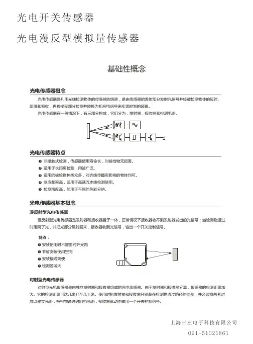
光电开关V31000安全操作规定前言光电开关V31000是一款常用的工业安全设备,主要是通过红外线或激光器等光学原理来检测物体的位置、形状、颜色等,并将信号转换为电信号,以达到控制电机、气缸等设备的目的。
本文主要介绍工作中如何正确使用和维护光电开关V31000,保障生产安全和设备正常运行。
适用范围本规定适用于使用本公司生产的V31000光电开关的相关人员,包括装配、维修和使用等环节。
安全注意事项1. 电气安全1.在安装、维护等操作过程中,必须先切断电源,并使用电源锁定装置等安全措施。
2.禁止在开关上方或附近工作时,触碰或拆卸掉有电部分。
3.使用光电开关前,应仔细阅读使用手册,并按照说明操作,避免出现误操作导致事故。
4.维修时,应采用适量工具松开螺丝,以避免对设备造成不可逆伤害。
5.禁止自行改变电路连接方式和线路,以免发生电器故障或引发火灾。
2. 机械安全1.在安装、维护等操作过程中,必须先切断动力源,并使用锁止装置等安全措施。
2.禁止在操作过程中将手臂、手指、头部或其他身体部位靠近正在运行的光电开关。
3.禁止使用不符合标准的带有液压、汽动等高压装置的设备操作开关来防止设备造成损坏,或者防止人员伤害。
4.禁止擅自调节开关工作距离或设备参数,防止设备出现意外事故。
3. 环境安全1.禁止在易爆、易腐蚀的环境中使用光电开关。
2.室外使用光电开关时,应采取防水、防尘措施,以确保正常使用。
3.在使用光电开关的环境中决不允许操作其他设备,以免对光电开关的工作造成干扰或损坏。
维护保养1.定期清洁光电开关内部灰尘和杂物,并检查电缆、接头等是否有松动、老化、损伤等情况。
2.保持开关周围的环境清洁,并避免灰尘、异物等进入开关内部。
3.长期不使用的光电开关应进行保管,采取防尘、防潮、防虫等措施,以免影响其正常运行。
4.第一次使用之前,应进行灵敏度和输出端检验,并做好相关记录,以便日后查找问题或进行维修保养。
总结本规定列举了光电开关V31000的安全注意事项及维护保养方法,以及操作时需要注意的各个环节。
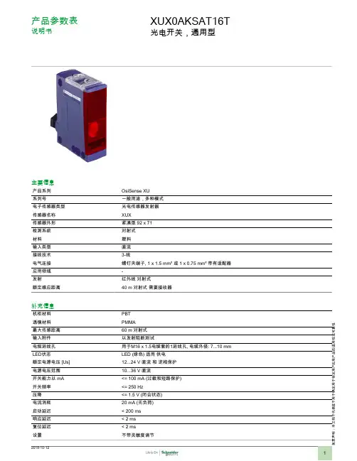
责声明:本文档不代表或不用于确定用于特定用户应用产品的适用性或可靠性产品参数表说明书XUX0AKSAT16T光电开关,通用型主要信息产品系列OsiSense XU 系列号一般用途,多种模式电子传感器类型光电传感器发射器传感器名称XUX传感器外形紧凑型 92 x 71检测系统对射式材料塑料输入类型直流接线技术3-线电气连接螺钉夹端子, 1 x 1.5 mm² 或 1 x 0.75 mm² 带有适配器应用领域-发射红外线 对射式额定感应距离40 m 对射式 需要接收器补充信息机柜材料PBT 透镜材料PMMA最大传感距离60 m 对射式输入附件以发射阻断测试电缆进线孔用于M16 x 1.5电缆套的1进线孔, 电缆外径: 7...10 mm LED状态LED (绿色) 适用 供电额定电源电压 [Us]12...24 V 直流 和 逆相保护电源电压范围10...36 V 直流开关能力以 mA <= 100 mA (过载和短路保护)开关频率<= 250 Hz压降<= 1.5 V (闭合状态)电流消耗20 mA (无负荷)启动延迟< 200 ms 响应延迟< 2 ms 复位延迟< 2 ms 设置不带灵敏度调节深度77 mm高度92 mm宽度31 mm产品重量0.2 kg环境产品认证CECSAUL运行温度-25...55 °C贮存环境温度-40...70 °C抗振动7 gn, 振幅 = +/- 1.5 mm (f = 10...55 Hz) 符合 IEC 60068-2-6抗冲击30 gn (持续时间 = 11 ms) 符合 IEC 60068-2-27IP 保护等级IP65 双重绝缘 符合 IEC 60529IP67 双重绝缘 符合 IEC 60529可持续性RoHS法规(日期代码:YYWW)符合 - 自从 2009年第14周 - Schneider Electric declaration of conformitySchneider Electric declaration of conformityREACh法规有毒有害物质含量均在REACH规定的范围之内有毒有害物质含量均在REACH规定的范围之内合同保修阶段18 个月尺寸图尺寸(1)Ø 5.5 x 7 细长孔(2)Ø 5.5 x 9 细长孔(3)Ø 5.5 孔接线接线图发射器 DC(1) 输入未连接:光束形成。
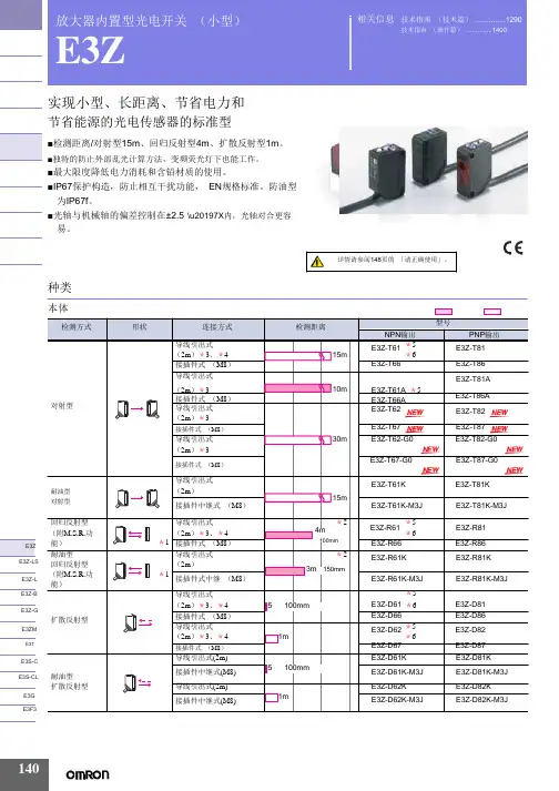
放大器内置型光电开关 (小型)E3Z实现小型、长距离、节省电力和节省能源的光电传感器的标准型■检测距离/对射型15m 、回归反射型4m 、扩散反射型1m 。
■独特的防止外部乱光计算方法,变频荧光灯下也能工作。
■最大限度降低电力消耗和含铅材质的使用。
■IP67保护构造,防止相互干扰功能, EN 规格标准。
防油型 为IP67f 。
■光轴与机械轴的偏差控制在±2.5°\u20197X 内,光轴对合更容 易。
种类相关信息 技术指南 (技术篇) (1290)技术指南 (操作篇) (1400)E3Z 注. 防油型号的回归反射型与标准的回归反射型检测距离不同。
*1. 不附带反射板,根据不同用途,有7种反射板可供选择购买。
*2. 检测距离是使用E39-R1S 时距离。
另外传感器与反射板间的距离请设定在 []内的数值以上的范围。
*3. 上表中标有*3的产品表示有导线0.5m 也是标准品,请在型号末尾标明导线长度。
(例:E3Z-T61 0.5M ) *4. 上表中标有*4的产品表示有接插件中继型 (M12)型号末尾带有-M1J 。
(例:E3Z-T61-M1J ) *5. 上表中标有*5的产品表示e-CON 接插件中继型。
(导线长度0.3m/0.5m/2m )。
型号末尾带有-ECON 。
例如E3Z-□6□-ECON 。
详细情况请参照1381页。
连接接插件有单面e-CON 接插件 E39-ECON □ (导线长度2m/5m )和两端e-CON 接插件 E39 -ECONW □ (导线长度0.5~2m 0.1m 单位) 2种。
e-CON 是FA 设备、连接器制作商的标准化规格。
*6. 备有夹紧式e-CON 接插件中继型 (导线长度2m ) 。
型号末尾带有-ECON-C (例:E3Z-T61-ECON-C 2M ) 。
接插件有单侧e-CON 接插件型 E39-ECON □M (导线长度2m/5m ) 和两端e-CON 接插件型 E39-ECONW □ (导线长度0.5~2m 0.1m 为单位)。
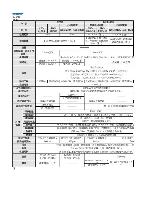
1)回归反射型传感器的检测距离和检测物体是对RF-230反射镜的值。
而且,检测距离是反射镜的可设定范围。
传感器可检测0.1m以内的物体。
2)扩散反射型传感器的检测距离是以白色无光泽纸(200×200mm)作为检测物体的。
3)如果装有狭缝透光罩(另售),可以检测3×6mm的物体。
4)如果传感器要在周围温度-15°C以下使用,请与经销商联系。
1c器不附带安装支架,请从另售的传感器安装支架例中选择(3种类型)。
注:1)回归反射型的检测距离是专门对于RF-230反射镜的值。
而且,检测距离是反射镜的可设定范围。
传感器可以检测0.1m以内的物体。
2) NX5系列中备有入光时ON型传感器(带后缀“A”的型号)和遮光时(非入光时)ON 型传感器(带后缀“B”的型号)。
以下型号的产品,若电源断开,输出继电器状态仍与检测物体时相同。
(若电源线断开,输出工作仍可以和检测物体时相同。
)请参阅每个型号的输出工作附件 ·RF-230(反射镜)5m电缆长度型备有5m 长电缆长度型(标准:2m )。
动P-P10%2VA以下起)0~+70°C C500V时m受光器各1 140g性负荷)时)时)。
ContentsImportant safety instructions 5Taking care of your remote control 6Cleaning and servicing 6First things first 7Basic features and benefits 7Packing checklist 7Your LCD TV overview 8Front panel view 8Rear panel view 9Basic connection 11Connecting the power cord 11Connecting an antenna 11Connecting DVD/VCR/AV equipment 12Connecting a camera, camcorder or video game 12Connecting headphones 13Connecting a PC or Notebook 13Remote control overview 14Getting started 18Power On 18Setup Wizard 18Changing channels 18Adjusting the volume 18OSD Navigation 19Navigating the OSD using the remote control: 19Advanced Features 20Empowering Key: Scenario Mode and Favourite Channels 20PIP/PBP/POP 22Parental Control 22Troubleshooting 23Product specifications 24English5Important safety instructionsRead these instructions carefully. Save them for fu-ture reference.1 Follow all warnings and instructions marked onthe product.2 Unplug this product from the power outlet be-fore cleaning. Use a soft, moist cloth for clean-ing. Do not use liquid or aerosol cleaners.3 Do not use this product near water. Do not spillwater or any other liquid on the product.4 Do not place this product on an unstable cart,stand, or table. The product may fall, causing serious damage to the product.5 Slots and openings are provided for ventila-tion; to ensure reliable operation of the prod-uct and to protect it from overheating. These openings must not be blocked or covered. The openings should never be blocked by placing the product on a bed, sofa, rug, or other simi-lar surface. This product should never be placed near or over a radiator or heat register, or in a built-in installation unless proper ventilation is provided.6 This product should be operated from the typeof power source indicated on the label. If you are unsure of the type of power source avail-able, consult your dealer or local power com-pany before use.7 Do not step on or place heavy objects on thepower cord. Carefully route the power cord and any cables away from foot traffic. Do not locate this product where persons will step on the cord.8 If an extension cord is used with this product,make sure that the total ampere rating of the equipment plugged into the extension cord does not exceed the extension cord ampere rating. Also, make sure that the total rating of all products plugged into the wall outlet does not exceed the fuse rating.9 Never push objects of any kind into this prod-uct through cabinet slots as they may touch dangerous voltage points or short out parts that could result in a fire or electric shock. 10 Do not attempt to service this product yourself,as opening or removing covers may expose you to dangerous voltage points or other risks. Re-fer all servicing to qualified service personnel.11 Unplug this product from the wall outlet andrefer servicing to qualified service personnel under the following conditions:a. When the power cord or plug is damaged or frayed.b. If liquid has been spilled into the product.c. If the product has been exposed to rain or water.d. If the product does not operate normally when the operating instructions are fol-lowed. Adjust only those controls that are covered by the operating instructions since improper adjustment of other controls may result in damage and will often require extensive work by a qualified technician to restore the product to normal condition.e. If the product has been dropped or the case has been damaged.f. If the product exhibits a distinct change in performance, indicating a need for service.12 Only use the correct power cord (provided inyour accessories box) for this product. Always disconnect the power cord from the wall outlet before servicing or disassembling this equip-ment.E n g l i s h6Taking care of your remote controlFollow these steps to ensure proper care of your remote control:• Handle the remote control with care. Dropping it, placing it in direct sunlight, or allowing it to getwet may cause damage.• Do not tamper with the batteries, and keep them away from children.• When you anticipate that the remote control will not be used for an extended period, remove thebatteries to prevent possible damage from battery leakage.• Dispose of batteries according to local regulations. Recycle if possible.Cleaning and servicingWhen cleaning your LCD TV, follow these steps:1 Power off the TV.2 Disconnect the power cord.3 Use a soft, moist cloth. Do not use liquid or aerosol cleaners.E n g l i s h8Your LCD TV overviewFront panel viewNo. Item DescriptionHeadphone Connects to headphones.Input Select source.When the OSD is on, press this button to confirm selection Vol Down Volume down.When the OSD is on, functions the same as the Left arrow Vol Up Volume up.When OSD is on, functions the same as the Right arrow Channel Down Channel down.When the OSD is on, functions the same as the Down arrow Channel Up Channel up.When the OSD is on, functions the same as the Up arrow Menu Turns the OSD menu ON and OFFPowerTurns the Power ON and OFFEnglishNo. Item DescriptionTuner Connects to the outdoor antenna cableAV1 / SCART 1 In Supports an external device with a SCART cable(for RGB, CVBS, S-Video,Audio left/right input)Out In TV mode, connects to your VCR In or PVR In with SCART cable to re-cord TV programsAV2 / SCART 2 In Supports external device with a SCART cable(for RGB, CVBS, S-Video,YPbPr/YCbCr, Audio left/right input)Out In TV mode, connect to your VCR In or PVR In with a SCART cable to re-cord TV programsAudio Out Connects to the audio jack input of your external device.AV3Audio-R Connects to the Audio-R output of your DVD, VCR player using the redcomposite cableAudio-L Connects to the Audio-L output of your DVD, VCR player using the whitecomposite cablePr/Cr Connects to the Component- Pr/Cr output of your DVD, VCR player usingthe red component cablePb/Cb Connects to the Component- Pb/Cb output of your DVD, VCR player us-ing the blue component cableY Connects to the Component-Y output of your DVD, VCR player using thegreen component cable9E n g l i s hDISPLAY MUTETV RECALL MENUMPXSWAP ACTIVE POSITIONSIZE/MODEINDEX SUBTITLE TELETEXT REVEALSIZE MIX SUBPAGE HOLDVOL PIP/PBP/POPCHOKENTERAV SCART PCSLEEP ZOOM WIDE SRS1234567809Teletext keysSUBPA G E H O L D Remote control overviewEnglishTeletext keysItem DescriptionINDEX Go to the index page SUBTITLE Show subtitlesTELETEXT Press to switch from TV/AV to Teletext mode. REVEAL Press to reveal hidden teletext information.SIZE Press once to zoom teletext page to 2X; press again to resume. MIX Press to overlay teletext page on the TV image, i.e. subtitles.HOLDPress to pause the current teletext page in multi-page viewing mode. Color buttons (R/G/Y/B)Operates corresponding button on the teletext page.There are five main OSD menus. These are: Picture, Audio. Use the following method to easily navigate these menus.OKUse the OSD to define your “e” Empowering Key setting: Scenario mode or Favourite channel. The default for the “e” key is the Scenario mode. Follow these steps: Menu > Empowering > e Key Setting. Choose between “Favourite channel” or “Scenario mode.” Now, when you press the “e” key, your chosen selec-Scenario ModePress the“e”Empowering key and use the Scenario mode to select pre-defined audio and video settings for optimal enjoyment of the following scenarios: Standard, Movie, Sport, Concert, Game, User; and smoothly presents moving images.Scenario Mode Design DirectionStandard mode allows you to watch your favourite channels with sharp, brilliantimagery via adaptive brightness and contrast adjustments. Clear-sounding audio isprovided by SRS performance.For comfortably enjoying movies at home, Movie mode displays dim scenes inclear detail; compensates for colour; and smoothly presents moving images. Thisis accomplished through optimal Gamma correction plus saturation, brightnessand contrast adjustments. Movie mode makes the most of high-definition movieViewing your favourite channelsOn the remote control, if you press the “e” Empowering key for less than 1 second, the favourite channel table will pop up. Your currently selected favourite channel will be highlighted. To view your other favourite channels, press the “e” Empowering key again to toggle the TV channels sequentially according to your favourite list.In TV, AV, SCART and PC mode, press PIP/PBP/POP button once to display using picture- in- picture (PIP). Press twice to display using picture- by- pic-In SCART and PC mode, press PIP/PBP/POP button three times to display picture-on-picture (POP). Then, the POP screens will display the subsequent TV channels one-by-one.PBP (Picture by Picture)PIP (Picture in Picture)EnglishTroubleshootingBefore you call the Acer service center, please check the following items:The following is a list of possible situations that may arise during the use of your LCD TV. Easy answers and solutions are provided for each one.There is no picture or sound.• Make sure the power cord is properly inserted in the power outlet.• Make sure the input mode selector is set to the correct source.• Make sure the antenna at the rear of the TV is properly connected.• Make sure the main power switch is turned on.• Make sure the volume is not set to minimum or the sound is not set to mute.• Make sure the headphones are not connected.• Reception other than those of broadcasting stations can be considered.Picture is not clear.• Make sure the antenna cable is properly connected.• Consider whether TV signals are being properly received.• Poor picture quality can occur due to a VHS camera, camcorder, or other peripheral being connectedat the same time. Switch off one of the other peripherals.• The ‘ghost’ or double image may be caused by obstruction to the antenna due to high rise buildingsor hills. Using a highly directional antenna may improve the picture quality.• The horizontal dotted lines shown on the pictures may be caused by electrical interference, e.g. hairdryer, nearby neon lights and etc. Turn off or remove these equipment.Picture is too dark, too light or tinted.• Check the color adjustment.• Check the brightness setting.• Check the sharpness function.• Fluorescent lamp may have reached the end of service life.Remote control does not work.• Check the batteries of the remote control.• Make sure the remote sensor window is not blocked or under strong fluorescent lighting.• Try to clean the remote control sensor lens on the TV with a soft cloth.• Use the buttons (hot keys) on the TV before the remote control works.If the above items do not solve your technical issue, please refer to the warranty card for service information.E n g l i s hProduct specificationsItem SpecificationPanel specifications Resolution1366 x 768 pixels Brightness (typical.) 500 nits Contrast Ratio (typical.) 800:1 Display colors16.7 M Viewing Angle (typical.) H:170 ; V:170Response Time (typical.)12 ms (gray to gray)Power supply Input100V to 240 V-AC. Max. power consumption 210 WPower Saving5 WMechanical Dimensions (W x H x D mm) 1018 x 616 x 210 mm Swivel angle 40 degrees(R20 & L20) Weight (kg) / (lbs.) 20.7kg / 45.6lbs.Wall MountingYesTerminal AV1/ SCART1 SCART(RGB,CVBS,S-Vidoe,Audio R/L )AV2/ SCART2 SCART(RGB,CVBS,S-Video,YPbPr/CbCr,Audio R/L ) AV3 RCA for YPbPr/CbCr,Audio R/L AV4 RCA for CVBS, Audio R/L AV5 S-Video, Audio R/L PC D-sub Yes DVI-D(HDCP) Yes PC audio-in Yes Audio-out YesHeadphonesYesAudio system 3D surround YesSpeakers 10 W + 10 WSRSWOW。
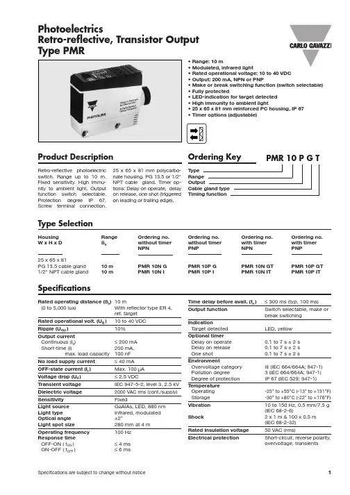
1PhotoelectricsRetro-reflective, Transistor Output Type PMR•Range: 10 m•Modulated, infrared light•Rated operational voltage: 10 to 40 VDC •Output: 200 mA, NPN or PNP•Make or break switching function (switch selectable)•Fully protected•LED-indication for target detected •High immunity to ambient light•25 x 65 x 81 mm reinforced PC housing, IP 67•Timer options (adjustable)Product DescriptionRetro-reflective photoelectric switch. Range up to 10 m.Fix ed sensitivity. High immu-nity to ambient light. Output function switch selectable.Protection degree IP 67.Screw terminal connection.25 x 65 x 81 mm polycarbo-nate housing. PG 13.5 or 1/2"NPT cable gland. Timer op-tions: Delay on operate, delay on release, one shot (triggered on leading or trailing edge).Type SelectionHousing Range Ordering no.Ordering no.Ordering no.Ordering no.W x H x DS nwithout timer without timer with timer with timer NPN PNP NPN PNP 25 x 65 x 81PG 13.5 cable gland 10 m PMR 10N G PMR 10P G PMR 10N GT PMR 10P GT 1/2" NPT cable gland10 mPMR 10N IPMR 10P IPMR 10N ITPMR 10P ITSpecificationsRated operating distance (S n )10 m (0 to 5,000 lux)With reflector type ER 4,ref. targetRated operational volt. (U B )10 to 40 VDC Ripple (U rpp )10%Output currentContinuous (I e )≤200 mA Short-time (I)200 mA,max. load capacity 100 nFNo load supply current ≤40 mA OFF-state current (I r )Max. 100 µA Voltage drop (U d )≤2.5 VDC Transient voltage IEC 947-5-2, level 3, 2.5 kV Dielectric voltage 2000 VAC rms (cont./supply)Sensitivity Fixed Light source GaAlAs, LED, 880 nm Light type Infrared, modulated Optical angle ±2°Light spot size 280 mm at 4 m Operating frequency 100 Hz Response time OFF-ON (t ON )≤4 ms ON-OFF (t OFF )≤6 msTime delay before avail. (t v )≤300 ms (typ. 100 ms)Output function Switch selectable, make or break switching IndicationTarget detected LED, yellow Optional timer Delay on operate 0.1 to 7 s ±2 s Delay on release 0.1 to 7 s ±2 s One shot 0.1 to 7 s ±2 sEnvironmentOvervoltage category III (IEC 664/664A; 947-1)Pollution degree 3 (IEC 664/664A; 947-1)Degree of protection IP 67 (IEC 529; 947-1)Temperature Operating -25°to +55°C (-13°to +131°F)Storage -30°to +80°C (-22°to +176°F)Vibration 10 to 150 Hz, 0.5 mm/7.5 g (IEC 68-2-6)Shock2 x 1 m & 100 x 0.5 m (IEC 68-2-32)Rated insulation voltage 50 VAC (rms)Electrical protectionShort-circuit, reverse polarity,overvoltage, transients2PMRSpecifications (cont.)Selection of FunctionSwitch 1 2 3PMR ... .PMR ... .T1 Break switching 9 One shot, leading edge - Break switching8 One shot, trailing edge - Make switching7 One shot, trailing edge - Break switching 5 Delay on release - Break switching 3 Delay on operate - Break switching 10One shot, leading edge - Make switching2 Make switching4 Delay on operate - Make switching 6 Delay on release - Make switching Don't careUpper postion ON (Mode 1)Lower position OFF (Mode 0)Housing material Body PC, grey Front PC, black CoverPC, blackCable glandPA, black, reinforced Mounting bracket Steel, blackConnection Screw terminal 5 x 2 x 1 mm 2Cable gland PG 13.5 or 1/2" NPT for cable 6 to 10 mm Weight90 gConnection DiagramTruth TableAccessoriesDelivery Contents•Photoelectric switch: PMR •Cable gland•Installation instruction •Mounting bracket•Packaging:Corrugated cardboard (environmentally friendly recycling material)•Reflectors: ER series•MB02 mounting bracket 90 mm long for mounting PMR from behind3PMROperation Diagramt = Time delaytv = Power ON delayDimensionsPMRPMR with angle bracketo r 1/2" N P TLED indication。

光电开关接线图
The Standardization Office was revised on the afternoon of December 13, 2020
1)接近开关有两线制和三线制之区别,三线制接近开关又分为NPN型和P NP型,它们的接线是不同的。
请见下图所示:
2)两线制接近开关的接线比较简单,接近开关与负载串联后接到电源即可。
3)三线制接近开关的接线:红(棕)线接电源正端;蓝线接电源0V端;黄(黑)线为信号,应接负载。
而负载的另一端是这样接的:对于NPN型接近开关,应接到电源正端;对于PNP型接近开关,则应接到电源0V端。
4)接近开关的负载可以是信号灯、继电器线圈或可编程控制器PLC的数字量输入模块。
5)需要特别注意接到PLC数字输入模块的三线制接近开关的型式选择。
PL C数字量输入模块一般可分为两类:一类的公共输入端为电源0V,电流从输入模块流出(日本模式),此时,一定要选用NPN型接近开关;另一类的公共输
入端为电源正端,电流流入输入模块,即阱式输入(欧洲模式),此时,一定要选用PNP型接近开关。
千万不要选错了。
6)两线制接近开关受工作条件的限制,导通时开关本身产生一定压降,截止时又有一定的剩余电流流过,选用时应予考虑。
三线制接近开关虽多了一根线,但不受剩余电流之类不利因素的困扰,工作更为可靠。
7)有的厂商将接近开关的“常开”和“常闭”信号同时引出,或增加其它功能,此种情况,请按产品说明书具体接线。
纽曼数码播放器—A3用户手册VM 206.2您好:感谢您选用本公司生产的产品!为了使您尽快轻松自如地操作本产品,我们随机配备了内容详尽的用户手册,您可以获取有关产品介绍、使用方法等方面的知识。
使用您的播放器之前,请仔细阅读我们随机提供的所有资料,以便您能更好地使用该产品。
在编写本手册时我们非常认真和严谨,希望能给您提供完备可靠的信息,然而难免有疏漏之处,请您给予谅解并由衷地欢迎您批评和指正。
如果您在使用该产品的过程中发现什么问题,请及时拨打我们的服务热线,感谢您的支持和合作!请随时备份您的数据资料到您的台式(笔记本)计算机上。
本公司对于因软件、硬件的误操作、产品维修、电池更换或其它意外情况所引起的个人数据资料的丢失和损坏不负任何责任,也不对由此而造成的其它间接损失负责。
同时我们无法控制用户对本手册可能造成的误解,因此,本公司将不对在使用本手册过程中可能出现的意外损失负责,并不对因使用该产品而引起的第三方索赔负责。
本手册中的信息如有变更,恕不另行通知。
本手册信息受到版权保护,其任何部分未经本公司事先书面许可,不准以任何方式影印和复制。
本公司保留对本手册、三包凭证及其相关资料的最终解释权。
标准号Q/SD 001-2007标准备案号QB/440301L2150-2007注意事项★禁止儿童单独玩耍本机。
★请不要在特别热、冷、多尘或潮湿的环境中使用播放器,避免水滴溅在机器上。
★使用时不要让播放器摔落、或与硬物摩擦撞击,否则可能会导致播放器表面磨花、电池脱落或其它硬件损坏。
★建议对于不同类型的文件建立相应的文件夹,进行目录管理。
★在下列情况下请进行充电:☆如在正常操作中播放器电池图标为并自动关机。
☆操作按键没有反应。
★尽量避免在特别干燥环境下操作播放器,以防静电。
★请及时备份存放在播放器中的个人数据资料。
★建议在驾驶机动车或自行车时不要使用耳机,请保证行车安全。
★使用耳机时如果音量过大,可能导致永久性的听力受损。
光电开关工作原理【1】(返回)创作者轻秘张日期:贰零贰贰年1月8日(人):电感式接近开关电容式接近开关红外线光电开关位移传感器霍尔开关磁性开关光电开关工作原理型号说明术语解释接线图号常用发射镜应用图例注意事项见的光波是380n m-780n m,发射波长为780n m-1m m的长射线称为红外线,浙江省洞是利用被检测物体对红外光束的遮光或反射,由同步回路选通而检测物体的有无,其物体的足够量的光线反射到接收器,于是光电开关就产生了开关信号。
当被检测物体的表面光亮或其反光率极高时,漫反射式的光电开收器,当被检测物体经过且完全阻断光线时,光电开关就产生了检测开关信号。
接收器。
当被检测物体经过发射器和接收器之间且阻断光线时,光电开关就产生了开关信号。
当检测物体是不透明时,对射式光电开检测物体经过U型槽且阻断光轴时,光电开关就产生了检测到的开关量信号。
槽式光电开关比较安全可靠的适合检测高速变化,分辨测物体不在相近区域的检测。
通常光纤传感器分为对射式和漫反射式。
的光线反射回漫反射开关的接受器,所以检测距离和被检测物体的表面反射率将是决定接受器接材料的反射率参考图如下所示:材料反射率材料反射率白画纸90%不透明黑色塑料14%报纸55%黑色橡胶4%餐巾纸47%黑色布料3%包装箱硬纸板68%未抛光白色金属表面130%洁净松木70%光泽浅色金属表面150%干净粗木板20%不锈钢200%透明塑料杯40%木塞35%半透明塑料瓶62%啤酒泡沫70%不透明白色塑料87%人的手掌心75%检测距离状态时,由于光学透镜会被环境中的污物粘住,甚至会被一些强酸性物质腐蚀,以至降低使用参数特性,这些变量尽管已列位移传感器工作原理和参数(返回)1. 原理简介感器又称为线性传感器,它分为电感式位移传感器,电容式位移传感器,光电式位移传感器,超声波式位移传感器我厂所生产的是电感式位移传感器。
传感器是一种属于金属感应的线性器件,接通电源后,在开关的感应面将产生一个交变磁场,当金属物体接近此感涡流而吸取了振荡器的能量,使振荡器输出幅度线性衰减,然后根据衰减量的变化来完成无接触检测物体的目的。